

Megger PAT300, PAT350, PAT320 Quick Start Manual
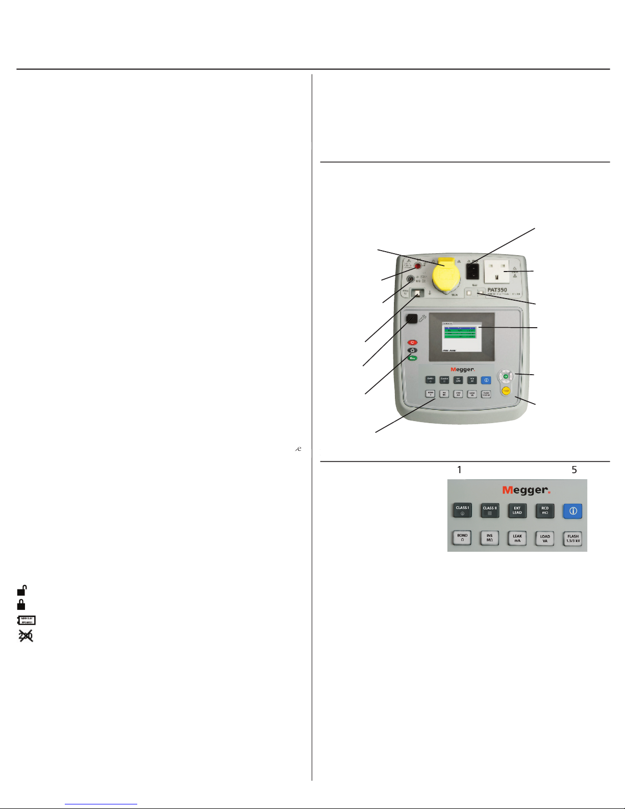
Getting started
Appliance test
socket 110 V
Flash test socket
(PAT 350 only
)
Firmware
upgrade port
Power off /
Escape and
Home keys
Test keypad –
See Test key layout
Extension lead
/ IEC lead test
socket
Appliance test
socket (230 V)
Fuse checker
Display
Display
navigation
UP/DOWN/
LEFT/RIGHT
and OK
TEST button
Earth bond and
insulation
test probe socket
NOTE: Do not connect any equipment until the PAT tester
has been switched on and passed a self test.
post
Note: The PAT320 does not include the Flash test option.
The following safety warnings and precautions
must
be read and understood before
the supply should be checked by a qualifi ed electrician.
the instrument if there are any signs of damage.
All test leads, probes and clips must be in good order, clean and with no broken or
cracked insulation.
Probes and clips should be held behind the fi nger guard.
Test leads not used during a measurement should be disconnected from the
appliance tester.
For dual voltage testers, both sockets can be live simultaneously.
Only connect one asset to the PAT during testing.
Tests should be carried out in the order recommended below. An appliance that
fails a test should be repaired before further testing is carried out.
Only perform an operational test after the earth bond and insulation tests
have been completed, as this test operate at mains voltage.
During testing, ensure no hazard will exist as a result of normal running or
under fault conditions.
During testing the unit under test (asset) should not be touched, other than
using the appropriate accessories, as faulty appliances can present a shock
hazard.
Do not touch the exposed parts of test leads during tests as hazardous
voltages may be present due to potentially faulty appliance.
Do not touch the IEC extension lead socket pins especially during a test, as
hazardous voltages may be present due to a potentially faulty appliance
Assets should not be routinely Flash tested. Where fl ash testing is required,
refer to further guidance on Flash testing, section 4.5.
Replacement fuses must be of the correct rating and type. Refer to section 6.3
The USB connection should only be used by approved service personnel,
nothing should be connected to the USB port during testing.
Only use NiMH rechargeable 9V PP3 battery, do not use a non rechargeable type
as this could become dangerous if charged by the instrument.
Serviceable fuses should only be replaced with those that are suitably rated
In case of an emergency use an easily accessible power point
insulation test, warns that a hazardous voltage may exist at the test lead
probes
A 9 V PP3 rechargeable NiMH battery is fi tted to allow fast
Warning:
1. Switch off the instrument and disconnect the instrument from any electrical
circuits.
2. Remove the battery cover.
3. Remove the old battery and refi t a new one, observing the terminal polarity.
4. Replace the cover and retaining screw.
Test group 1 to 5 Description
Extension (found on computers, kettles etc)
lead test
with RCDs
10 A or 25 A
Test groups summary
Warning: Do not switch the instrument on with the fuse cover
removed or test leads connected.
1. Switch off the instrument and disconnect (the instrument) from any
electrical circuits.
2. Remove the fuse cover.
3. Replace the blown fuse with the correct type and rating.
4. Replace the fuse cover.
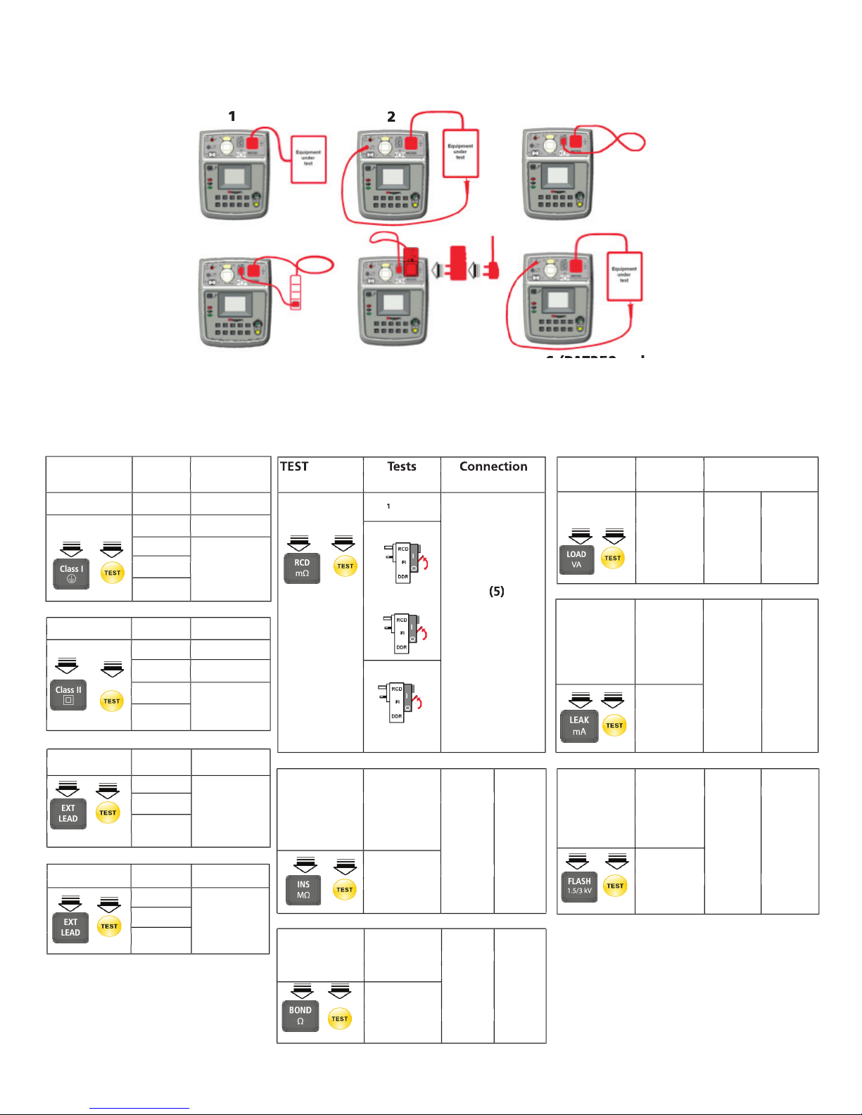
TEST Tests Connection
options run: required:
CLASS I
INS
LOAD (1)
BOND
INS (4)
Polarity
Warning:
TEST Tests Connection
x I
1 xI 0º
1 xI 180º
5 xI 0º
250 V (1) (2)
500 V
25 A
10 A (1) (2)
200 mA
TEST Tests Connection
test
(1) (2)
I-diff
I-touch (1) (2)
I-sub
Flash
test (6) (6)
IEC LEAD
BOND
INS (3)
Polarity
CLASS II
INS (2)
LOAD (1)
(Touch)
 Loading...