

Page 1
Quick Start guide (English UK)
PAT300 Series Portable Appliance Testers
M
G Safety Warnings and symbols used
The following safety warnings and precautions must be read and understood before
the instrument is used. They must be observed during use.
For safety, only connect the PAT to a supply that is properly earthed. If in doubt,
the supply should be checked by a qualified electrician.
Do not use the instrument if there are any signs of damage.
All test leads, probes and clips must be in good order, clean and with no
broken or cracked insulation.
Probes and clips should be held behind the finger guard.
Test leads not used during a measurement should be disconnected from the
appliance tester.
For dual voltage testers, both sockets can be live simultaneously.
Only connect one asset to the PAT during testing.
Tests should be carried out in the order recommended below. An appliance that
fails a test should be repaired before further testing is carried out.
Recommended Sequence:
1. Earth Bond/ Continuity of the protective earth conductor (Class I devices)
2. Insulation test (or earth leakage)
In addition further tests can be performed
3. Operation test
4. Leakage test
Only perform an operational test after the earth bond and insulation tests
have been completed, as this test operates at mains voltage.
During testing, ensure no hazard will exist as a result of normal running or
under fault conditions.
During testing the unit under test (asset) should not be touched, other than
using the appropriate accessories, as faulty appliances can present a shock hazard.
Do not touch the exposed parts of test leads during tests as hazardous voltages
may be present due to a potentially faulty appliance.
Do not touch the IEC extension lead socket pins especially during a test, as
hazardous voltages may be present due to a potentially faulty appliance
Assets should not be routinely Flash tested. Where flash testing is required,
refer to further guidance on Flash testing, section 4.5 in the user guide.
Replacement fuses must be of the correct rating and type. Refer to section
6.3 in the user guide.
The USB connection should only be used by approved service personnel,
nothing should be connected to the USB port during testing.
Only use NiMH rechargeable 9V PP3 battery, do not use a non rechargeable type
as this could become dangerous if charged by the instrument.
Serviceable fuses should only be replaced with those that are suitably rated
In case of an emergency use an easily accessible power point
Safety symbols used on the instrument
F Caution: risk of electric shock
G Caution: refer to accompanying notes. When displayed at the start of an
insulation test, warns that a hazardous voltage may exist at the test lead probes
c Equipment complies with the relevant EU Directives
f Fuse
HV test lead in unlocked position
HV test lead in locked postion
Battery type fitted
DO NOT connect to 230 V supply
Battery function - A 9 V PP3 rechargeable NiMH battery is supplied to allow fast
restart should the PAT be unplugged and reconnected to an electrical supply in less
than 5 minutes.
Battery replacement
Warning: Do not switch the instrument on with the battery cover removed or
test leads connected.
Only use NiMH rechargeable batteries.
1. Switch off the instrument and disconnect the instrument from any electrical
circuits.
2. Remove the battery cover.
3. Remove the old battery and refit a new one, observing the terminal polarity.
4. Replace the cover and retaining screw.
Note: The PAT320 does not include the Flash test option.
Fuse replacement
Warning: Do not switch the instrument on with the fuse cover removed
or test leads connected.
1. Switch off the instrument and disconnect (the instrument) from any
electrical circuits.
2. Remove the fuse cover.
3. Replace the blown fuse with the correct type and rating.
4. Replace the fuse cover.
Getting started
NOTE: Do not connect any equipment until the PAT tester
has been switched on and passed a self test.
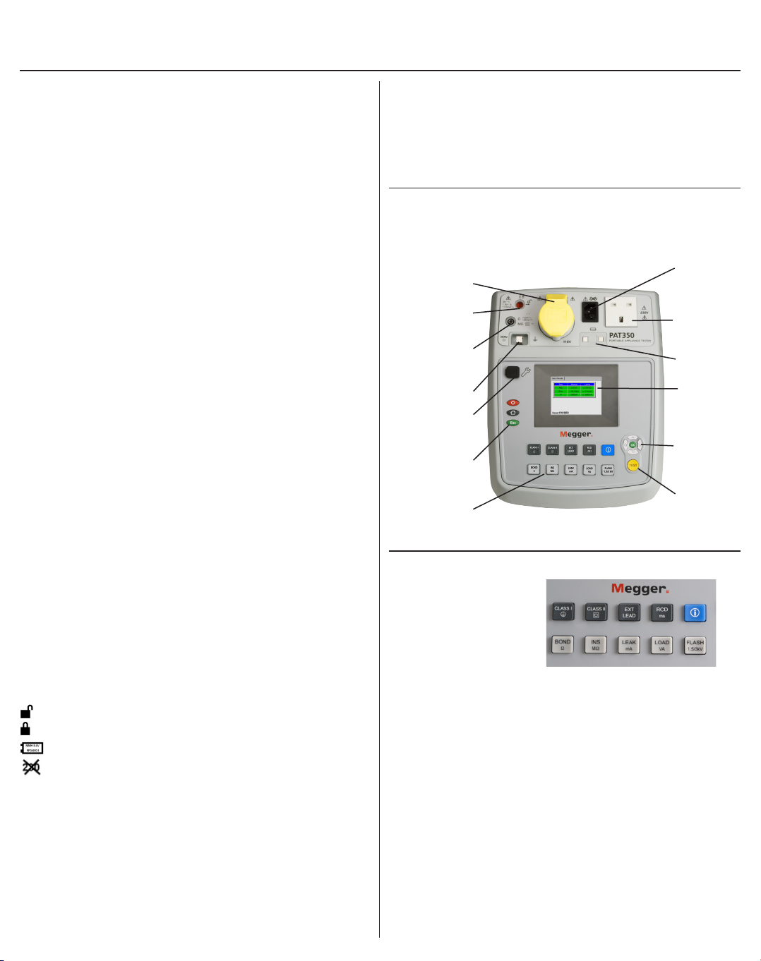
Instrument and test key layout
Appliance test
socket 110 V
Flash test socket
(PAT 350 only)
Earth bond and
insulation test
probe socket
Lead null post
Firmware
upgrade port
Power off /
Escape and
Home keys
Test keypad –
See Test key layout
Test key layout
Test groups summary
1 2
3
6 7 8 9 10
Test group 1 to 5 .....Description
1 Class I test ..................... For testing assets with an earth return conductor
2 Class II test .................... For testing assets without an earth return conductor
3 IEC lead and ................. For testing extension leads and IEC type power leads
Extension lead test ...... (found on computers, kettles etc)
4 RCD tests ....................... For testing Plug-in RCDs and extension leads fitted
....................................... with RCDs
5 Information ................... Provides technical support details
Individual tests 6 to 10
6 Bond Ω ........................Performs an earth bond/continuity test at 200 mA,
10 A or 25 A
7 INS MΩ ........................Performs an insulation test at either 250 V or 500 V
8 LEAK mA .....................Performs an earth leakage test
9 LOAD VA......................Performs a RUN test and measures the power drawn
10 1.5 kV/3 kV ..................Performs a flash test at the required voltage
Extension
lead/IEC lead
test socket
Appliance test
socket (230 V)
Fuse checker
Display
Display
navigation
UP/DOWN/
LEFT/RIGHT
and OK
TEST button
4 5
Page 2
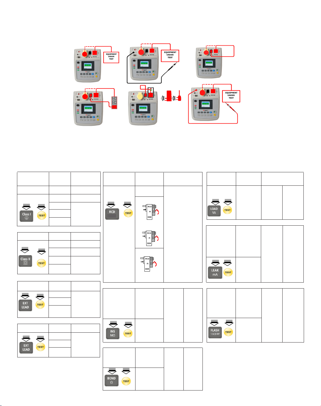
Testing Assets
Connection options for 230 V equipment
1 2
M
3
4
5
6 (PAT350 only)
Note: 110 V equipment connects to the 110 V socket. The PAT must be supplied from 110 V to test 110 V appliances.
An optional adaptor is available to allow the fixed lead of the PAT to be connected to a 110 V socket.
Test options – Class I, Class II, RCDs, IEC leads and extension leads
All tests assume the PAT is operating in AUTO mode. For manual mode and test options refer to the full user manual.
TEST Tests Connection
options run: required:
CLASS I
BOND (2)
INS
LOAD (1)
LEAK
CLASS II
INS (2)
LOAD (1)
LEAK
(Touch)
IEC LEAD
BOND
INS (3)
Polarity
EXT LEAD
BOND
INS (4)
Polarity
(2)
TEST Tests Connection
options: run: required:
RCD
1 x I 0º
mS
1 x I 180º
5 x I 0º
5 x I 0º
INS mΩ
Select Insulation CLASS I CLASS II
Class/voltage
and supply
type
250 V (1) (2)
500 V
BOND Ω
Select test Earth CLASS I CLASS II
current continuity
25 A
10 A (1) (2)
200 mA
1
/2 x I
(5)
TEST Tests Connection
options: run: required:
LOAD VA Load CLASS I CLASS II
test
(1) (2)
LEAK mΩ Leakage CLASS I CLASS II
Select current
leakage
type and
Class type
I-diff
I-touch (1) (2)
I-sub
FLASH 1500 V
Select test 3000 V CLASS I CLASS II
voltage
and Class
type
Flash
test (6) (6)
Warning: Flash testing is a destructive
test. Repetitive use can cause damage
to the equipment. Flash testing should
not be used for routine testing.
Printed in UK 2000-963, PAT300_QS_en-uk_V06
 Loading...