

Page 1

M
PAT32 Series
P o rtable Appliance Testers
USER GUIDE
GUIDE DE L’UTILISATEUR
GEBRAUCHSANLEITUNG
Page 2
SAFETY WARNINGS
✱ PAT 32 must be properly earthed. A supply socket that has a protective earth contact must be used.
✱ Test leads, probes and crocodile clips must be in good order, clean and with no broken or cracked insulation.
✱ Circuit connections and exposed metalwork of an appliance under test must not be touched.
✱ Tests must be performed in the specified sequence. If an appliance fails a test, the fault causing the failure must be
rectified before testing. Re-testing must commence from the start of the sequence.
✱ Replacement fuses must be of the correct size, type and rating. See 'Specification' section.
✱ The instrument must not be used in damp conditions or if any part of it is damaged.
✱ Safety Warnings and Precautions must be read and understood before the instrument is used. They must be observed
during use.
NOTE
THE INSTRUMENT MUST ONLY BE USED BY SUITABLY TRAINED AND COMPETENT PERSONS
.
Symbols used on the instrument
Evaluate display reading against appliance details and refer to this User Guide
Caution: Refer to accompanying notes.
Equipment complies with relevant EU Directives
Page 3

User Guide
Safety Warnings 2
General Description 4
Features and Controls 6
Test Mode Summary 7
Performing tests – General 9
Appliance Testing 10
Extension lead testing (UK) 14
Specifications 15
Accessories 18
Repair and Warranty 19
Guide de l’utilisateur
Avertissments de Securité 22
Description génerale 23
Dispositifs et Commandes 25
Sommaire de Mode d’essai 23
Exécution des essais – Géneralitiés 26
Mise à l’essai de l’appareil 29
Mise à l’essai de la Rallonge 33
Spécification 34
Accessoires 37
Réparation et Garantie 38
Gebrauchsanleitung
Sicherheitswarnung 42
Allgemeine Beschreibung 43
Funktionen und Steuerelemente 45
Zusammenfassung des Testmodus 46
Durchführung von Tests 48
Testen von Geräte 49
Verlängerrungskabeltest 53
Spezifikation 54
Zubehör 57
Reparaturen und Garantie 58
Contents
3
Page 4

Introduction
Megger PAT 32 series are designed to check the
electrical safety of any product fitted with an appropriate
mains plug, including information technology (IT)
equipment, domestic appliances, industrial appliances
and power tools.
The following tests are available:
• Circuit check
• Fuse check
• Earth Continuity test
• 10 Amp Earth Bond test
• 25 Amp Earth Bond test
• Insulation test
• Extension lead tests (ELT1 or ELT2
required)
- Polarity (UK only)
- Earth Bond
- Insulation
Tests are effected by plugging the portable appliance or
extension lead into the relevant socket and pressing the
relevant Test switch. The readings from each test are
shown on the unique analogue / digital liquid crystal
display.The measurement scale for Earth Bond is
marked with pass bands. This provides a rapid indication
of a test Pass or Failure and allows proper test results to
be kept.
Applications
Appliances and electrical equipment with Safety Class I,
Class II and Safety Class III insulation may be tested.
These classes of safety are defined in various IEC and
BS safety specifications, and in general are:-
Class I Appliances which have functional
insulation throughout and an
earth connected body i.e. an ‘Earthed‘
appliance.
Class II Appliances which have both functional
and additional insulation, and where
any metal parts cannot become ‘Live’
under fault conditions. This is ‘Double
Insulation’ indicated by .
Class I / II Appliances having part of the
enclosure which meets Class I
requirements and part which meets
Class II.
Class III Appliance where protection against
electric shock is provided by an SELV
supply. Class III construction is
indicated by the mark.
General Description
4
III
Page 5

Typical uses for Megger PAT 32 are:
• Periodic tests of equipment used in
Factories, Offices, Local Education
Authorities, Hospitals etc.
• Routine tests before and after hiring
electrical equipment.
• Basic tests following equipment repair.
• Tests by manufacturers and distributors.
Specifications
The Megger PAT 32 may be used to test equipment
originally manufactured to a range of specifications such
as:
• IEC 335 -1 / BS3456
• BS 2769
• BS 4533
• BS415
• BS 7002
Power cord
The colour code of the cord is:
Phase Brown
Protective Earth Yellow / Green
Neutral Blue
If using a fused plug, a 3 Amp fuse to BS 1362 should be
fitted.
Note: A plug severed from the power cord should be
destroyed, as a plug with bare conductors is hazardous
in a live socket outlet.
5
Page 6
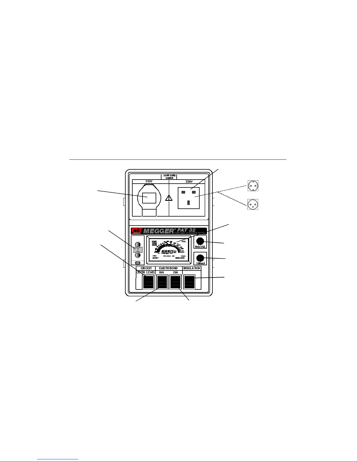
Features and Controls
6
Fuse test terminals
110 Volt Socket
to BS4343 /IEC309
230 V Socket
to BS1362
230 V Belgian / French socket
230 V
Circuit Test switch
10 A Earth Bond Test switch
25 A Earth Bond Test switch
Insulation Test switch
Earth Bond Test
Earth Continuity Test terminal
Analogue / Digital LCD
Page 7

Test Sequence
For safety reasons, it is important that appliance tests
are carried out in the correct sequence:-
• Circuit Test
• Fuse Test (if necessary)
• Earth Continuity Test
and / or
• Earth Bond Test
• Insulation Test
If a fault on an appliance is detected, testing must be
stopped and the fault rectified. Testing must then recommence from the beginning of the test sequence.
Circuit Test
A low voltage d.c. Resistance test of the Phase to
Neutral circuit.
FuseTest (if supply or appliance fuse is suspect)
Checks the continuity of most types of fuses when
removed from the appliance.
Earth Continuity Test
The earth continuity test may only be performed on
Class I (Earthed) appliances.The test checks protective
conductor continuity and the earth connection to the
metal parts of the appliance at a current of 100 mA.
This test is used where a higher current Earth Bond test
may cause damage to the appliance. Avery low voltage
(100 mV) is established between the main supply plug
earth pin and the metal parts of the appliance. The low
voltage of this test is designed to reveal bad connections
by not breaking down any oxide films.
Earth Bond Test
The Earth Bond test may only be carried out on Class I
(earthed) appliances.
The test checks protective conductor continuity and the
earth connection (or Bonding) to the metal parts of the
appliance. Avery low voltage is established between the
main supply plug earth pin and the metal parts of the
appliance.
A choice of two Earth Bond tests is available:i) Passing a current of 10 Amp. Used for
appliances and equipment fused at 5 Amp or
less.
ii) Passing a current of 25 Amp. Used for
equipment fused at greater than 5 Amp.
Test Mode Summary
7
Page 8

Insulation Test
Checks the integrity of the insulation. For class I
appliances, the test voltage is applied to the main supply
plug between Phase and Neutral (shorted together) and
the Earth pin, which is held at earth potential.
For Class II appliances, the Earth Bond lead is used to
make the return connection from the appliance to the
instrument earth bond terminal.
The PAT 32 develops 500 V d.c. into 0.5 MΩ and
complies with the 1mA load current requirement.
Caution:- If an Insulation test fails, there will be a
leakage path to earth somewhere on the appliance.
Any metal parts of the appliance could become ‘Live’
and give the user an electric shock. Do not touch
the appliance when applying the test.
Extension Lead Test
Using the Megger ELT1 or ELT2 optional accessory,
the PAT 32 checks Continuity, Earth Bond and Insulation
of both 230 V and 110 V extension leads. (110 V adaptor
required). ELT1 (UK version) also checks the Polarity of
the extension lead connections.
Error displays
Internal faults within the instrument are indicated by error
messages consisting of the letter ‘ ‘ followed by a 2 digit
number. Continuous testing on the Earth bond ranges
may cause the display of , and the analogue pointer
to move off the left hand end of the scale. Cease testing
and allow the instrument to cool for about 15 minutes.
If any error message displays, and the instrument will not
re-set itself, return the instrument for service. See Repair
and Warranty.
Test Mode Summary
8
Page 9

Appliance Visual Checks
Before carrying out PAT32 electrical tests, the appliance
and its accessories must be given a visual inspection to
identify any physical faults that may not be revealed by
electrical testing.
Visually examine and check the condition of the:-
• Supply plug
• Plug fuse type and rating (if applicable)
• Mains cord
• Cord connection grommet (if applicable)
• Mains On /Off switch
• Auxiliary switches
• Conducting / Insulated parts of the outer case
• Removable covers which must be in place.
Any significant faults or defects must be rectified before
proceeding with the PAT 32 electrical tests.
Auto Nulling and Self check
When not being operated, PAT 32 will periodically carry
out measurement nulling. The word is displayed.
Press any Test switch to override this function.
A self check function is also continuously performed on
the selected test range.
If testing is interrupted, for instance due to the appliance
not being switched On, or the mains fuse being ruptured,
testing must be repeated from the start of the test
sequence in the corrected condition. i.e. with a sound
fuse and with the appliance switched On.
Performing Tests – General
9
Tests must be performed with the appliance
switched On and with good fuse(s) fitted.
Page 10
Preliminary Testing Procedure
1. Plug the PAT32 into the 230 V mains
power supply, and switch the supply on. Full
screen details are displayed, and a self check is
carried out. On completion, the ‘Home’ screen is
displayed.
2. Determine the Class / type of the appliance to
be tested.
Class I – Earthed appliance
Class II – Double insulated appliance
Class III - S.E.L.V appliance
3. Plug the appliance into the appropriate socket
on the instrument front panel and switch the
appliance On.
Appliance Testing Procedure
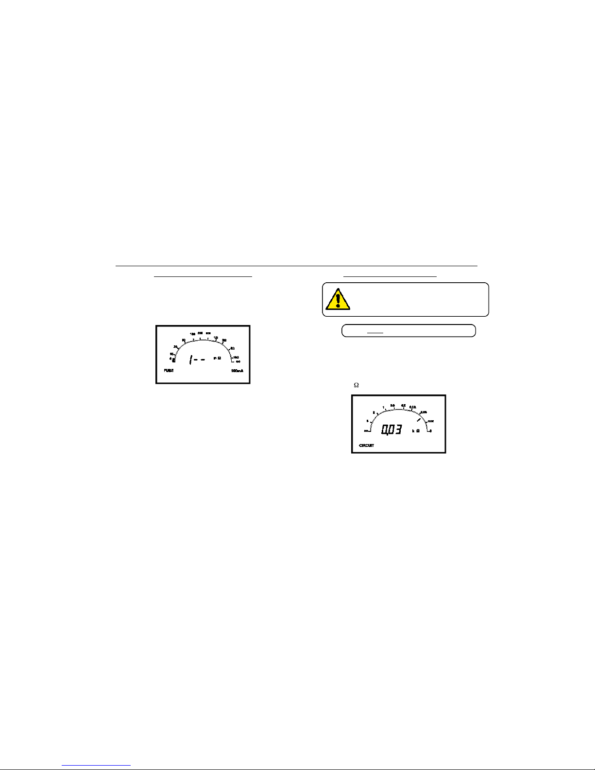
Circuit Test
1. Press and hold the Circuit Test switch. The
Circuit screen is displayed.
2. Phase to Neutral resistance is displayed
directly in k .
Note:- Readings of approximately 0,01 kΩ can be
expected from appliances incorporating large wound
components such as large transformers and motors.
Heating appliances may give readings of approximately
0,02 kΩ.
3. Release the Test switch.
Appliance Testing
10
Tests must follow the given sequence
If fault(s) are indicated, cease testing and
rectify. Re-commence testing from the
start of the test sequence.
Page 11
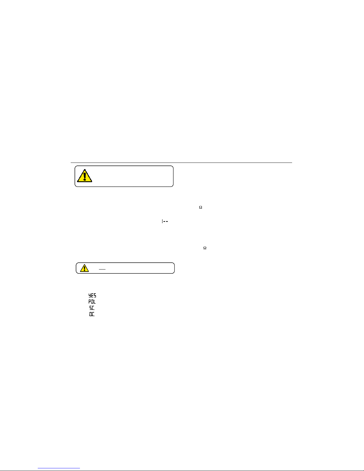
Note:- During the test, a display of indicates Open
circuit. Check that the appliance is switched On, that any
fuses fitted are good, the continuity of the power cord is
good and that the appliance itself is not open circuit.
Appliances with a switch mode power supply may indicate
Open circuit. In this case, omit the Circuit test.
Note:- If the appliance circuit appears to be Open circuit,
fuses (if applicable) may be checked as follows:
Fuse Check
1. Remove the suspect fuse from the appliance.
With the ‘Home‘ screen displayed (no switches
pressed) press the suspect fuse across the
contacts.
A good fuse is indicated by the display of
accompanied by a continuous beep note.
Earth Continuity Test (Class I appliances only)
1. With the ‘Home‘ screen displayed (no switches
pressed) connect the Earth Bond test lead to
the 100mA terminal.
2. Firmly connect the crocodile clip to the metalwork of
the appliance.
3. Earth continuity resistance is displayed directly
in m .
4. Disconnect the Earth Bond test lead.
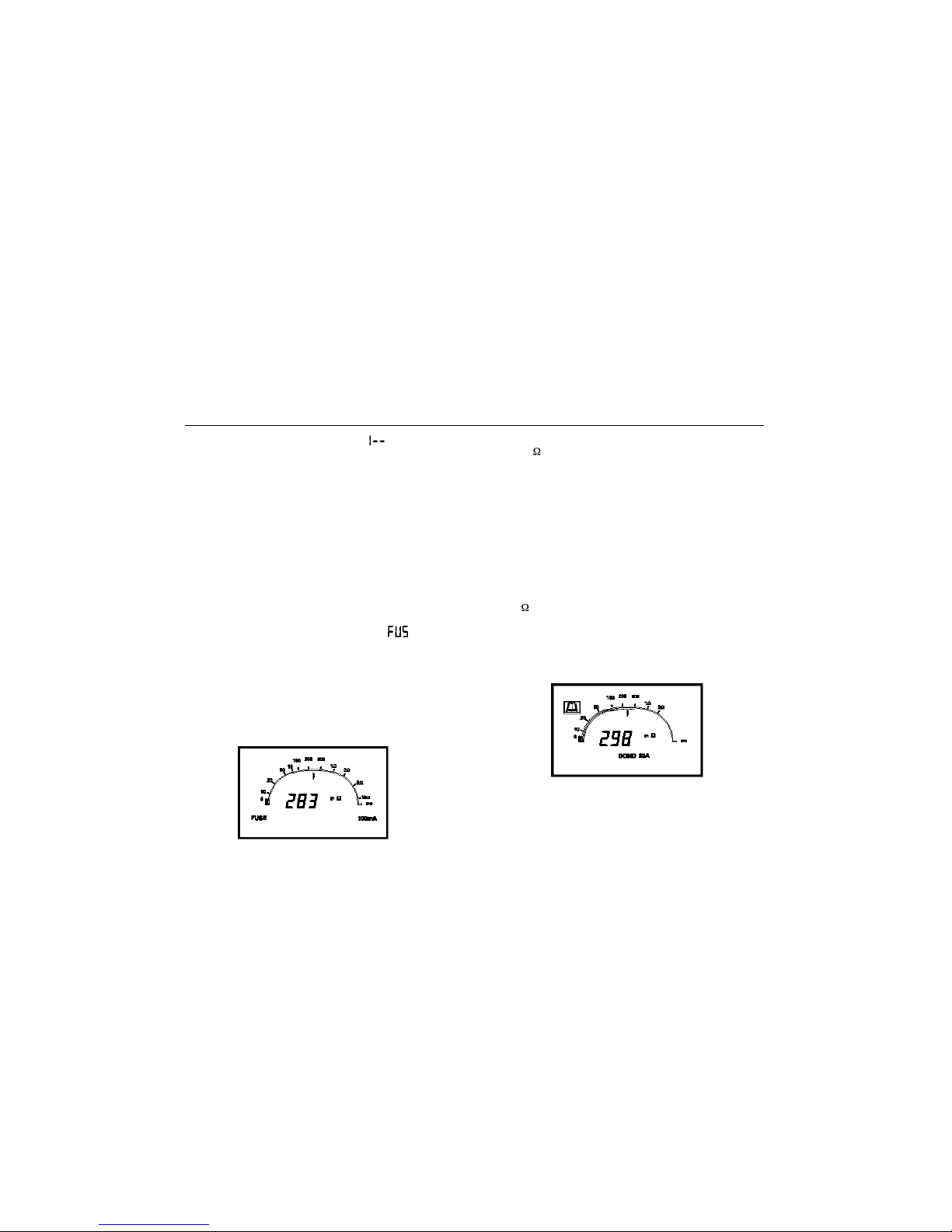
Earth Bond Test (Class I appliances only)
1. With the ‘Home‘ screen displayed (no switches
pressed) connect the Earth Bond test lead to
the 10A/25A terminal.
2. Firmly connect the crocodile clip to the
metalwork of the appliance.
3. Press and hold either the 10A or the 25A test
switch. The Earth Bond screen is displayed.
4. Earth Bond resistance is displayed directly in
m .
5. Release the Test switch.
6. Disconnect the Earth Bond test lead.
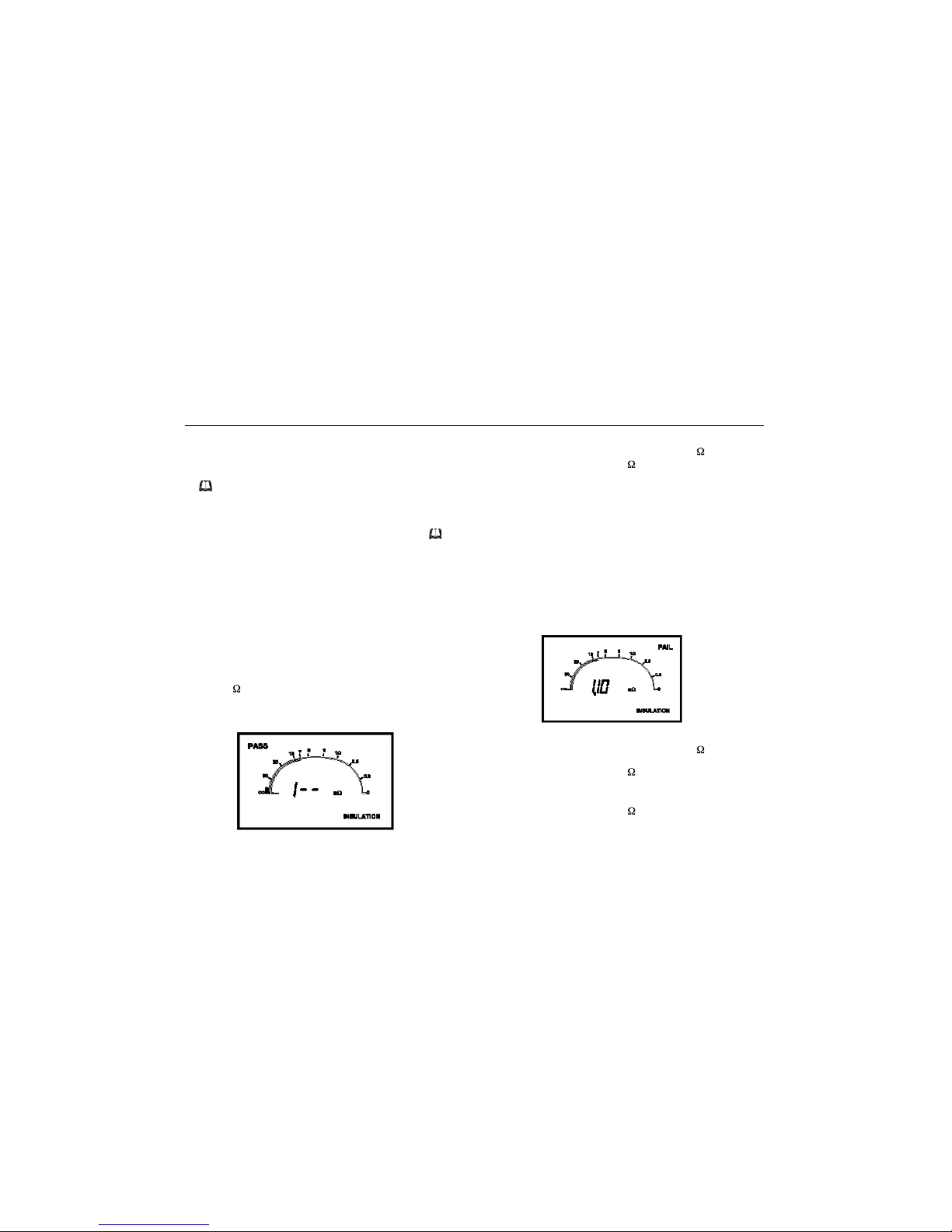
A successful test is indicated on the solid scale line and
the word PASS is displayed.
As a general rule, an appliances should have an Earth
Bond resistance of less than 100 mΩ. Appliances with
long supply leads will give higher readings due to
conductor resistance. Corrections may be applied if lead
11
Page 12
resistance figures are available and lead length is
measured.
A reading of between 100 mΩ and 500 mΩ will be
indicated on the broken scale line together with the display
of . Refer to the appliance manufacturer.
Readings greater than 500 mΩ are indicated by t h e
flashing display of the word FAIL.
On the 10 Amp range, the flashing display of w i l l
appear for resistance greater than 600 mΩ, indicating that
the test current is below a satisfactory test level. It is
suggested that the 25 A m p range should then be used.
Insulation Te s t
Class I Appliance
1. Press and hold the Insulation Test switch. The
Insulation screen is displayed.
2. Insulation resistance value is displayed directly
in M .
3. Release the Test switch.
As a general rule, Class I appliances should have an
insulation resistance value greater than 1 M .
A reading of less than 0.25 M is indicated with the word
FAIL.
Class II Appliance
1. Connect the Earth Bond test lead (or probe if
available) to the 10A/25A terminal.
2. Press and hold the Insulation Test switch. The
Insulation screen is displayed.
3. Using the crocodile clip, probe areas of likely
leakage around the insulation areas. i.e. joins /
apertures / metal parts.
4. Release the Test switch.
5. Disconnect the Earth Bond test lead.
As a general rule, Class II appliances should have an
insulation resistance value greater than 2 M .
A reading of greater than 2 M is indicated on the solid
scale line together with the word PASS.
A reading of less than 0.25 M is indicated with the word
FAIL.
Appliance Testing
12
Page 13

Between 0.25 M and 2 M , the is displayed. In this
instance, the user must judge whether to PA S S or FA I L
the test, depending upon the insulation class of the
a p p l i a n c e .
Appliance Testing
13
Page 14
Plug the extension lead into the appropriate socket on the
instrument front panel.
Circuit Test
1. Press and hold the Circuit Test switch. The
Circuit screen is displayed.
For an unterminated extension lead a reading of
should be displayed. Any other reading indicates a faulty
lead and must be investigated.
2. Release the Test switch.
Polarity Test
Plug Extension Lead Tester ELT1 into the socket end of
the Extension lead (use the adaptor for 110 V leads).
1. Press the Circuit Test switch twice.
2. Check the polarity of the extension lead against
the following display options:
- Polarity Correct
- Connections reversed
- Short Circuit
- Open Circuit
Earth Bond Test
1. Connect the Earth Bond test lead to the 2 5 A
terminal.
2. Firmly connect the crocodile clip to the E LT1
metal stud.
3. Press and hold the 25A Test switch. The Earth
Bond screen is displayed.
4. Earth Bond resistance is displayed directly in
m .
5. Release the Test switch.
6. Disconnect the Earth Bond test lead.
Insulation Test (Class I leads only)
1. Press and hold the Insulation Test switch. The
Insulation screen is displayed.
2. Insulation resistance value is displayed directly
in M .
3. Release the Test switch.
Extension Lead Testing (UK)
– ELT1 Required
14
Do not plug the ELT1 into a live circuit
If fault(s) are indicated, cease testing
and rectify. Re-commence testing from
the start of the test sequence.
Page 15

Circuit Test
Meter reading range: 0 to 9,9 kΩ
Range Resolution Accuracy
0 to 1 kΩ 0,01 kΩ 2,5% of reading ± 0,02 kΩ
1 kΩ to 2 kΩ 0,02 kΩ 2,5% of reading ± 0,02 kΩ
2 kΩ to 5 kΩ 0,05 kΩ 2,5% of reading ± 0,05 kΩ
5 kΩ to 9,9 kΩ 0,1 kΩ 2,5% of reading ± 0,1 kΩ
Open Circuit Voltage: 4,5 V d.c.
Short Circuit Current: 1 mA d.c.
Fuse Check
5 V. d.c. 0,5 mA Typical
Earth Continuity Test
Range Resolution Accuracy
0 to 999 mΩ 1 mΩ 2,5% of reading ±5 mΩ
900 mΩ to1990 mΩ 10 mΩ 2,5% of reading ±10 mΩ
Open Circuit Voltage: Typically 100 mV d.c.
Constant Current: Typically 100 mA into <1Ω
10A Earth Bond Test
Meter reading range: 0 to 1990 mΩ
Range Resolution Accuracy
0 to 600 mΩ 1 mΩ 2,5% of reading ±5 mΩ
600 to 999 mΩ 1 mΩ Current below level for
900-1990 mΩ 10 mΩ satisfactory Bond test.
Transfer to 25A test
Pass Band Limits: 100 and 500 mΩ
Open Circuit Voltage: Typically 3 V rms a.c. 50 Hz
Specification
15
Page 16

Specification
Spec Point Current 10A into 100 mΩ at 240 V. 8,7 A into 100 mΩ at 230 V.
Short Circuit Current Typically 12 A
25A Earth Bond Test
Meter reading range: 0 to 1990 mΩ
Range Resolution Accuracy
0 to 999 mΩ 1 mΩ 2,5% of reading ±5 mΩ
900-1990 mΩ 10 mΩ 2,5% of reading ±10 mΩ
Pass Band Limits: 100 and 500 mΩ
Open Circuit Voltage: Typically 6 V rms a.c. 50 Hz
Spec Point Current: Typically 25A into 100 mΩ (10A into 500 mΩ)
Short Circuit Current Typically 36.5 A
Insulation Test
Meter reading range: 0-99 MΩ
Range Resolution Accuracy
0 to 10 MΩ 0,1 MΩ 2,5% of reading ± 0,1 MΩ
10MΩ to 20 MΩ 0,2 MΩ 5% of reading ± 0,2 MΩ
20MΩ to 50 MΩ 0,5 MΩ 5% of reading ± 0,5 MΩ
50MΩ to 99 MΩ 1 MΩ Indication only
Pass Band limit: 2 MΩ (Class I) – 7 MΩ (Class II)
Open Circuit Voltage: ≤ 600 V d.c.
Spec Point Voltage ≥ 500 V d.c. into 0.5 MΩ
Short Circuit Current: < 2 mA
General
Temperature Range
Operating: 5 ˚C to +40˚ C
Storage: -25˚C to +65˚ C
16
Page 17

Humidity Range
Operating: ≤ 90% RH at 25˚C
Supply 230 V(+10% -6%) 50 Hz 300 VA
Safety Meets the requirements for double insulation to IEC 1010 (1995) EN
61010 (1995)
Fuses 2 x 2 A (F) 20 mm x 5 mm HBC, IEC 127/1
2 x 250 mA (F) mm x 5 mm HBC, IEC 127/1
Mains power cord fused plug (as applicable) – 3 Afuse to BS1362
EMC In accordance with IEC61326 including amendment No.1
Dimensions 314 mm x 152 mm x 206 mm (12,5” x 6” x 8”)
Weight 3,75 kg (8,25 lb approx.)
Cleaning: Wipe the disconnected instrument with a clean cloth dampened with
soapy water or Isopropyl Alcohol (IPA).
Specification
17
Page 18

Supplied Part Number
User Guide 6172-265
Accessory Pouch 6420-108
Earth Bond test lead with crocodile clip 6280-043
Optional Extras
Extension lead tester ELT1 (UK) 6111-130
Extension lead tester ELT2 (France & Germany) 6111-320
Earth Bond lead and Probe EP1 6320-225
Bare wire adaptor lead with 3 pin plug to BS1363/A 6111-230
Appliance safety log book (complete) 6131-813
Log book test sheets (pack of 30 sheets) 6171-417
Log book test stickers (Pack of 3 sheets [72 stickers]) 6171-418
Training Media
VHS Video: ‘Portable Appliance Testing‘ 6131-999
Accessories
18
Page 19

The instrument circuit contains static sensitive devices,
and care must be taken in handling the printed circuit
board. If the protection of an instrument has been
impaired it should not be used, and be sent for repair by
suitably trained and qualified personnel. The protection is
likely to be impaired if, for example, the instrument
shows visible damage, fails to perform the intended
measurements, has been subjected to prolonged
storage under unfavourable conditions, or has been
exposed to severe transport stresses.
New Instruments are Guaranteed for 1 Year from the
Date of Purchase by the User.
Note: Any unauthorized repair or adjustment will
automatically invalidate the Warranty.
Instrument Repair and Spare Parts
For service requirements for Megger Instruments contact:
Megger Limited or Megger
Archcliffe Road ValleyForge Corporate Center
Dover 2621 Van Buren Avenue
Kent, CT17 9EN. Norristown, PA19403
England. U.S.A.
Tel: +44 (0) 1304 502100 Tel: +1 (610) 676-8579
Fax: +44 (0) 1304 207342 Fax: +1 (610) 676-8625
or an approved repair company.
Approved Repair Companies
A number of independent instrument repair companies
have been approved for repair work on most Megger
instruments, using genuine Megger spare parts. Consult
the Appointed Distributor / Agent regarding spare parts,
repair facilities and advice on the best course of action to
take.
Returning an Instrument for Repair
If returning an instrument to the manufacturer for repair, it
should be sent freight pre -paid to the appropriate
address. A copy of the Invoice and of the packing note
should be sent simultaneously by airmail to expedite
clearance through Customs. A repair estimate showing
freight return and other charges will be submitted to the
sender, if required, before work on the instrument
commences.
Repair and Warranty
19
Page 20

Notes
20
Page 21

M
PAT32 Series
P o rtable Appliance Testers
GUIDE DE L’UTILISATEUR
Page 22

AVERTISSEMENTS DE SECURITE
• L'unité PAT32 doit être mise à la terre correctement. Une prise d'alimentation électrique qui a un contact
de protection de mise à la terre doit être utilisée.
• Les câbles d'essai, les détecteurs et les pinces-crocodile doivent être en bon état, propres et sans
isolation rompue ou fissurée.
• Les connexions de circuit et les parties métalliques exposées d'un appareil à l'essai ne doivent pas être
touchées.
• Les essais doivent être effectués dans la séquence spécifiée. Si un appareil ne passe pas avec succès un
essai donné, la faute causant la panne doit être rectifiée avant une nouvelle mise à l'essai. La nouvelle
mise à l'essai doit commencer à partir du début de la séquence.
• Les fusibles de remplacement doivent être de la taille, du type et de la qualité corrects. Voir la section
'Spécification'.
• L'instrument ne doit pas être utilisé dans des conditions humides ou en cas de dégâts à une partie
quelconque de celui-ci.
• Les avertissements et les précautions de sécurité doivent être lus et compris avant utilisation de
l'instrument. Ils doivent être observés pendant l'utilisation de celui-ci.
REMARQUE
CONFIEZ L
’UTILISATION DE CET INSTRUMENT A UN PERSONNEL QUALIFIE ET COMPETENT.
Symboles utilisés sur cet instrument
Evaluer la lecture provenant de l'affichage par comparaison aux détails relatifs à l'appareil et se
rapporter à ce Guide de l'Utilisateur.
Attention: Consultez les notes jointes.
Cet équipement respecte les directives en viguer de l’UE.
22
Page 23

Introduction
La série Megger PAT 32 a été conçue pour contrôler la
sécurité électrique de tout produit équipé d’une fiche
secteur approriée, y compris les appareils ménagers, les
matériels industriels et les outils électroportatifs.
Les essais suivants sont disponibles :
• Contrôle des circuits
• Contrôle des fusibles
• Essai de continuité à la terre
• Essai de liaison à la terre 1 A
• Essai de liaison à la terre 25 A
• Essai d’isolement
• Essai des cordons prolongateurs
(ELT1 ou ELT2 requis)
• Polarité (Royaume-Uni seulement)
• Liaison à la terre
• Isolement
Les essais s’effectuent en branchant l’appareil portatif ou
le cordon prolongateur dans la prise puis en appuyant
sur le commutateur d’Essai correspondant. Les lectures
de chaque essai sont présentées sur l’afficheur
analogique/numérique unique à cristaux liquides.
L’échelle des mesures de Liaison à la Terre est marquée
par des bandes passantes. Ceci fournit une indication
rapide de la Réussite ou de l’Echec du test et permet de
conserver les résultats de mesure appropriés.
Les appareils et matériels électriques d’application avec
un isolement de Sécurité Classe I, Class II et Sécurité
Classe III peuvent être testés. Ces classes de sécurité
sont définies dans diverses prescriptions de sécurité IEC
et BS et sont en général :
Classe I Appareils qui disposent d’un isolement
fonctionnel sur tout le circuit et d’une
carrosserie reliée à la terre, c’est à dire
un appareil "à la terre".
Classe II Appareils qui disposent d’un isolement
fonctionnel et d’un isolement
supplémentaire, et dans lesquels
aucune pièce métallique ne peut
passer "sous tension" en cas de
défaut. Il s’agit du "double Isolement"
indiqué par .
Classe I /II Appareils dont une partie de
l’enveloppe répond aux exigences de
la Classe I et l’autre répond à la
Classe II.
Classe III Appareils où la protection contre
l’électrocution est assurée par une
alimentation SELV (circuit à tension de
sécurité extra-basse). La construction
de Classe III est indiquée par la
marque .
Description générale
23
III
Page 24

Les emplois typiques du Megger PAT 32 sont :
• Les essais périodiques des matériels
utilisés dans les usines, les groupes
scolaires, les hôpitaux, etc.
• Les essais de routine avant et après
location d’un matériel électrique
• Les essais de base à la suite de la
réparation d’un matériel.
• Les essais réalisés par les fabricants et
distributeurs.
Spécifications
Le Megger PAT 32 peut être utilisé pour tester les
matériels fabriqués d’origine suivant un éventail de
prescriptions telles que :
• IEC 335 – 1 / BS3456
• BS 2769
• BS 4533
• BS 415
• BS 7002
Cordon d’alimentation
Le code couleur du cordon est :
Phase Marron
Terre de protection Jaune / Vert
Neutre Bleu
EN cas d’utilisation d’une fiche à fusible, un fusible 13 A
à la norme BS 1362 devra être utilisé
Note : Une fiche désolidarisée du cordon d’alimentation
devra être détruite, car avec des conducteurs dénudés,
une telle fiche peut s’avérer dangereuse dans une prise
sous tension.
24
Description générale
Page 25

25
Dispositifs et commandes
Bornes d'essai
de fusibles
Prise 110V
IEC309/BS 4343
Prise 230 V
Commutateurs
d'essai de circuit
Commutateur d'essai de
liaison à la terre 10 A
Commutateur d'essai de
liaison à la terre 25 A
Commutateur
d'essai d'isolation
Borne d'essai de
liaison à la terre
Borne d'essai de
continuité de mise
à la terre
Affichage
analogue/numérique
Page 26

26
Sommaire de mode d'essai
Séquence d'essai
Pour des raisons de sécurité, il est important d'effectuer
les essais de l'appareil dans la séquence correcte:
• Essai de circuit
• Essai de fusible (si besoin est)
• Essai de continuité de mise à la
terre
et/ou
• Essai de liaison à la terre
• Essai d'isolation
S'il y a détection d'une faute dans l'appareil, la mise à
l'essai doit être interrompue et la faute doit être rectifiée.
La mise à l'essai doit alors être reprise à partir du
commencement de la séquence d'essai.
Essai de circuit
Un essai de résistance basse tension à courant continu
du circuit phase au circuit neutre.
Essai de fusible (s'il y des doutes quant à l'alimentation
électrique ou au fusible de l'appareil) Vérifie la continuité
de la plupart des types de fusibles quand ils sont retirés
de l'appareil.
Essai de continuité de mise à la terre
L'essai de continuité de mise à la terre ne peut être
effectué que sur des appareils de la classe I. L'essai
vérifie la continuité du conducteur de protection et la
connexion de mise à la terre des parties métallique d'un
appareil à un courant de 100 mA. Cet essai est utilisé là
où un essai de liaison à la terre à courant plus élevé
pourrait causer des dégâts à l'appareil. Une tension très
basse (100 mV) est établie entre la broche de mise à la
terre de la prise principale d'alimentation électrique et les
parties métalliques de l'appareil. La basse tension de cet
essai est conçue pour mettre en évidence des
mauvaises connexions sans détruire des films d'oxyde
quelconques.
Essai de liaison à la terre
L'essai de liaison à la terre peut seulement être effectué
sur des appareils (mis à la terre) de la classe I.
L'essai vérifie la continuité du conducteur de protection
et la connexion (ou liaison) à la terre aux parties
métalliques de l'appareil. Une tension très basse est
établie entre la broche de mise à la terre de la prise
principale d'alimentation électrique et les parties
métalliques de l'appareil.
Un choix de deux essais de liaison à la terre est
disponible:
i) Passage d'un courant de 10 Ampères. Utilisé
pour des appareils et des équipements à fusible
ou à puissance nominale de 5 Ampères ou
moins.
ii) Passage d'un courant de 25 Ampères. Utilisé
pour des appareils et des équipements à fusible
ou à puissance nominale de 5 Ampères ou plus.
Avertissement: S'il existe une faute de liaison à la
terre et une faute d'isolation, une partie métallique
quelconque de l'appareil pourrait passer à l'état
"sous tension" et infliger à l'utilisateur un choc
électrique. Ne pas toucher l'appareil pendant la mise
en oeuvre de l'essai.
Page 27

27
Essai d'isolation
Vérifie l'intégrité de l'isolation. Pour les appareils de la
classe I, la tension d'essai est appliquée à la prise
d'alimentation électrique principale entre le fil phase et le
fil neutre (mis en court-circuit l'un par rapport à l'autre) et
la borne de terre, qui est maintenue au potentiel de terre.
Pour des appareils à isolation double, le câble de liaison
à la terre est utilisé pour réaliser la connexion de retour
de l'appareil à la borne de liaison à la terre de
l'instrument.
Le Megger PAT32 développe 500 V c.c. en 0,5 MΩ et
est conforme avec l’impératif d’intensité de charge de 1
mA.
Avertissement: Si un essai d'isolation échoue, il y
aura un trajet de fuite vers la terre quelque part dans
l'appareil. Toute pièce métallique de l'appareil
pourrait passer à l'état "sous tension" et infliger à
l'utilisateur un choc électrique. Ne pas toucher
l'appareil pendant la mise en oeuvre de l'essai.
Essai de rallonge
En utilisant l'accessoire facultatif Megger ELT2, l'unité
PAT32 vérifie la continuité, la liaison à la terre et
l'isolation à la fois des rallonges 230V et 110V. L'unité
ELT1 (version Royaume Uni) vérifie également la
polarité des connexions de rallonge.
Affichages d'erreurs
Des fautes internes au sein de l'instrument sont
indiquées par des messages d'erreur se composant de
la lettre ‘ ‘ suivie d'un nombre à 2 chiffres. Une mise à
l'essai en continu des domaines de liaison à la terre
peuvent provoquer l'affichage de la mention [Chaud]
et le passage de l'indicateur analogue à l'extrémité
gauche de l'échelle. Interrompre la mise à l'essai et
laisser refroidir l'instrument pendant environ 15 minutes.
S'il y a affichage d'un message d'erreur quelconque, et si
l'instrument ne se corrige pas de lui-même, retourner
l'instrument pour remise en état. Consulter la section
Réparation et Garantie.
Sommaire de mode d'essai
Page 28

28
Exécution des essais – Généralités
Vérifications visuelles de l'appareil
Avant d'effectuer les essais électriques de l'unité PAT32,
l'appareil et ses accessoires doivent subir une inspection
visuelle pour identifier toute faute physique qui pourrait
ne pas être détectée par la mise à l'essai électrique.
Examiner visuellement et vérifier l'état:
• de la prise d'alimentation électrique
• du type et de la spécification du fusible de la
prise (s'il y a lieu)
• du cordon d'alimentation électrique
• de l'oeillet de connexion du cordon (s'il y a lieu)
• du commutateur Marche/Arrêt d'alimentation
électrique
• des commutateurs auxiliaires
• des parties conductrices/isolées du boîtier
externe
• la mise en place de tout couvercle.
Il faut rectifier tout défaut ou toute défectuosité
d'importance avant de procéder aux essais électriques
de l'unité PAT32.
Mise à zéro automatique et auto-contrôle
En période de non utilisation, l'unité PAT32 exécutera
périodiquement une mise à zéro de mesure. Le mot ‘
‘ est affiché. Appuyer sur un commutateur Essai
quelconque pour obtenir la priorité vis-à-vis de cette
fonction.
Une fonction d'auto-contrôle est également exécutée en
continu sur le domaine d'essai choisi. Si la mise à l'essai
est interrompue, par exemple du fait que l'appareil n'est
pas en position de marche, ou si le fusible d'alimentation
électrique a claqué, la mise à l'essai doit être répétée du
début de la séquence d'essai dans la condition corrigée,
c'est-à-dire avec un fusible en bon état et avec l'appareil
en position de marche.
Les essais doivent être exécutés avec l'appareil
enclenché et après mise en place d'un ou de
fusible(s) en bon état.
Page 29

29
Procédure de mise à l'essai préliminaire
1. Brancher l'unité PAT32 dans le secteur
d'alimentation électrique 230V et mettre en
marche l'alimentation électrique. Il y affichage
des détails sur la totalité de l'écran, et un auto-
contrôle est effectué. Une fois celui-ci achevé, il
y affichage de l'écran ‘Home‘.
2. Déterminer le type de l'appareil à mettre à
l'essai.
Classe I– Appareil mis à la terre
Classe II – Appareil à isolation double
Appareils de Classe III SELV (circuit à
tension de sécurité extra-basse)
3. Brancher l'appareil dans la prise correspondante
sur le panneau avant de l'instrument et mettre
l'appareil en marche.
Procédures de mise à l'essai d'appareils
Essai de circuit
1. Appuyer sur et maintenir appuyé le
commutateur d'essai de circuit. L'écran Circuit
est affiché.
2. La résistance Phase à Neutre est affichée
directement en kΩ.
Note: On peut s'attendre à des valeurs de lecture
d'approximativement 0,01 kΩ en provenance d'appareils
incorporant des composants à enroulements importants
tels que des transformateurs et des moteurs de grande
taille. Les appareils de chauffage peuvent donner des
valeurs de lecture d'approximativement 0,02 kΩ.
3. Relâcher le commutateur d'essai.
Mise à l'essai de l'appareil
Les essais doivent suivre la séquence donnée
S'il y a indication d'une ou de faute(s),
interrompre la mise à l'essai et rectifier.
Recommencer la mise à l'essai depuis le
début de la procédure.
Page 30

Mise à l'essai de l'appareil
30
Note: Pendant l'essai, un affichage de indique un
circuit ouvert. Vérifier que l'appareil est enclenché, que
tous les fusibles sont en bon état, que la continuité du
cordon d'alimentation est bonne et que l'appareil luimême n'est pas en circuit ouvert.
Des appareils avec une alimentation électrique à
découpage peuvent indiquer un circuit ouvert. Dans ce
cas, omettre l'essai de circuit.
Note:- Si le circuit de l'appareil semble être un circuit
ouvert, on peut vérifier les fusibles (s'il y a lieu) comme
suit:
Vérification des fusibles
1. Retirer le fusible suspect de l'appareil. Avec
l'écran 'Home' affiché (sans pression sur un
commutateur quelconque), appuyer le fusible
sur les contacts.
Un fusible en bon état est indiqué par l'affichage de ,
accompagné d'une tonalité bîp continue.
Essai de continuité de mise à la terre (appareils de la
classe I seulement).
1. Avec l'écran 'Home' affiché (sans pression sur
un commutateur quelconque), relier le câble
d'essai de liaison à la terre à la borne 100 mA.
2. Relier fermement la pince-crocodile au boîtier
métallique de l'appareil.
3. La résistance de continuité de mise à la terre
est affichée directement en m .
4. Débrancher le câble d'essai de liaison à la terre.
Essai de liaison à la terre (appareils de la classe I
seulement)
1. Avec l'écran 'Home' affiché (sans pression sur
un commutateur quelconque), relier le câble
d'essai de liaison à la terre à la borne 10A/25A.
2. Relier fermement la pince-crocodile au boîtier
métallique de l'appareil.
3. Appuyer et maintenir appuyé soit le
commutateur d'essai 10A, soit le commutateur
d'essai 25A. L'écran Liaison à la terre est
affiché.
4. La résistance de liaison à la terre est affichée
directement en m .
5. Relâcher le commutateur d'essai.
6. Débrancher le câble d'essai de liaison à la terre.
En règle générale, un appareil devrait avoir une
résistance de liaison à la terre de moins de 100 mΩ.
Page 31

31
Des appareils ayant des cordons d'alimentation longs
donneront des valeurs de lecture plus élevées du fait de
la résistance des conducteurs. Des corrections peuvent
être appliquées si l'on dispose de chiffres de résistance
de cordon et si l'on mesure la longueur du cordon.
Une valeur de lecture comprise entre 100 mΩ et 500 mΩ
sera indiquée sur la ligne d'échelle à traits interrompus,
conjointement à l'affichage clignotant de . Consulter
le fabricant de l'appareil.
Des valeurs de lecture supérieures à 500 mΩ sont
indiquées par un affichage de , mot FAIL [Echec].
Dans le domaine 10 Ampères, l'affichage clignotant de
apparaîtra pour une résistance supérieure à 600 mΩ,
indiquant que le courant d'essai est inférieur à un niveau
d'essai satisfaisant. Il est fortement suggéré alors
d'utiliser le domaine de 25 Ampères.
Essai d'isolation
Appareil de la classe I
1. Appuyer sur et maintenir appuyé le
commutateur d'essai d'isolation. L'écran
Isolation est affiché.
2. La valeur de résistance d'isolation est affichée
directement en M .
3. Relâcher le commutateur d'essai.
En règle générale, les appareils de la classe I devraient
avoir une valeur de résistance d'isolation supérieure à
1 M . Une lecture de moins de 0.25 M est indiquée par
le au mot FAIL [Echec].
Appareil de la classe II
1. Relier le câble d'essai de liaison à la terre (ou le
détecteur s'il y a lieu) à la borne 10A/25A.
2. Appuyer sur et maintenir appuyé le
commutateur d'essai d'isolation. L'écran
Isolation est affiché.
3. En utilisant la pince-crocodile, mettre à l'essai
les zones de fuite probables au voisinage des
zones d'isolation, les blindages / les ouvertures /
les parties métalliques.
4. Relâcher le commutateur d'essai.
5. Débrancher le câble d'essai de liaison à la terre.
Page 32

32
En règle générale, les appareils à isolation double
devraient avoir une valeur de résistance d'isolation
supérieure à 2 M
Une valeur de lecture supérieure à 2 M est indiquée
par le mot PASS [Succès].
Une valeur de lecture inférieure à 0.25 M est indiquée
par le mot FAIL [Echec].
Entre 0.25 M et 2 M , un est affiché. Dans ce cas,
l'utilisateur doit décider du verdict PASS [Succès] ou
FAIL [Echec], en fonction de la classe d'isolation de
l'appareil.
Page 33

33
Brancher la rallonge dans la prise appropriée sur le
panneau avant de l'instrument.
Essai de circuit
1. Appuyer sur et maintenir appuyé le
commutateur d'essai de circuit. L'écran Circuit
est affiché. Pour une rallonge sans terminaison,
il devrait y avoir affichage de :--. Toute autre
valeur de lecture indique une rallonge
défectueuse et requiert une inspection.
2. Relâcher le commutateur d'essai.
3. Mettre le dispositif d'essai de rallonge ELT2
dans l'extrémité de prise de la rallonge (utiliser
l'adaptateur pour une rallonge 110V).
Ne pas brancher le dispositif ELT2 dans un circuit sous
tension.
4. Appuyer sur le commutateur de circuit à deux
reprises.
5. Vérifier la rallonge par rapport aux options
d'affichage suivantes:
- Continuité correcte
- Résistance haut
- Court-circuit
- Circuit ouvert
Essai de liaison à la terre
1. Relier le câble d'essai de liaison à la terre à la
borne 25A.
2. Relier fermement la pince-crocodile à la broche
métallique du dispositif ELT2.
3. Appuyer sur et maintenir appuyé le
commutateur d'essai 25A. L'écran Liaison à la
terre est affiché.
4. La résistance de liaison à la terre est affichée
directement en m .
5. Relâcher le commutateur d'essai.
6. Débrancher le câble d'essai de liaison à la terre,
Essai d'isolation (appareils de la classe I seulement).
1. Appuyer sur et maintenir appuyé le
commutateur d'essai d'isolation. L'écran
d'isolation est affiché.
2. La valeur de résistance d'isolation est affichée
directement en M .
3. Relâcher le commutateur d'essai.
Mise à l'essai de la rallonge le dispositif – ELT2 étant requis
S'il y a indication d'une ou de faute(s),
interrompre la mise à l'essai et rectifier.
Recommencer la mise à l'essai à partir
du début de la séquence.
Ne pas brancher le dispositif ELT2
dans un circuit sous tension.
Page 34

34
Spécification
Essai de circuit
Domaine de lecture de l'indicateur: 0 à 9,9 kΩ
Domaine Résolution Précision
0 à 1 kΩ 0,01 kΩ 2,5% de la valeur de lecture ± 0,02 kΩ
1 kΩ à 2 kΩ 0,02 kΩ 2,5% de la valeur de lecture ± 0,02 kΩ
2 kΩ à 5 kΩ 0,05 kΩ 2,5% de la valeur de lecture ± 0,05 kΩ
5 kΩ à 9,9 kΩ 0,1 kΩ 2,5% de la valeur de lecture ± 0,1 kΩ
Tension de circuit ouvert: 4,5 V d.c.
Courant de court-circuit: 1 mA d.c.
Vérification des fusibles
Typiquement 5V, sous courant continu de 0,5 mA
Essai de continuité de mise à la terre
Domaine Résolution Précision
0 à 999 mΩ 1 mΩ 2,5% de la valeur de lecture ±5 mΩ
900 mΩ à1990 mΩ 10 mΩ 2,5% de la valeur de lecture ±10 mΩ
Tension de circuit ouvert: Typiquement de 100 mV courant continu.
Courant constant: Typiquement de 100 mA dans <1Ω
Essai de liaison à la terre 10A
Domaine de lecture de l'indicateur: 0 à 1990 mΩ
Range Resolution Accuracy
0 à 600 mΩ 1 mΩ 2,5% de la valeur de lecture ±5 mΩ
600 à 999 mΩ 1 mΩ Courant inférieur au niveau pour
900 à 1990 mΩ 10 mΩ un essai de liaison satisfaisant.
Transfert à l'essai de 25A.
Limites passe-bande: 100 and 500 mΩ
Tension de circuit ouvert: Typiquement de 3 V rms a.c. 50 Hz
Courant de point spécifique – 10A dans 100 mΩ (240 V). 8,7 Adans 100 mΩ (230 V).
Courant de court-circuit: Typiquement 12 A
Page 35

35
Essai de liaison à la terre 25A
Domaine de lecture de l'indicateur: 0 à 1990 mΩ
Domaine Résolution Précision
0 à 999 mΩ 1 mΩ 2,5% de la valeur de lecture ±5 mΩ
900 à 1990 mΩ 10 mΩ 2,5% de la valeur ±10 mΩ
Limites passe-bande: 100 et 500 mΩ
Tension de circuit ouvert: Typiquement de 6 V rms a.c. 50 Hz
Courant de point spécifique: Typiquement 25Adans 100 mΩ (10A dans 500Ω)
Courant de court-circuit: Typiquement 36,5 A
Essai d'isolation
Domaine de lecture de l'indicateur: 0-99 MΩ
Domaine Résolution Précision
0 à 10 MΩ 0,1 MΩ 2,5% de la valeur de lecture ± 0,1 MΩ
10MΩ à 20 MΩ 0,2 MΩ 5% de la valeur de lecture ± 0,2 MΩ
20MΩ à 50 MΩ 0,5 MΩ 5% de la valeur de lecture ± 0,5 MΩ
50MΩ à 99 MΩ 1 MΩ Indication seulement
Limites passe-bande: 2 MΩ (Class I) – 7 MΩ (Class II)
Tension de circuit ouvert: ≤ 750 V d.c.
Tension de point spécifique: 560 V d.c. dans 2 MΩ nominale
Courant de court-circuit: Typiquement 2 mA
Généralités
Domaine de Température:
En fonctionnement: 5 ˚C à +40˚ C
Stockage: -25˚C à +65˚ C
Domaine d'humidité
En fonctionnement: ≤ 90 % d'humidité relative à 25˚C
Page 36

36
Spécification
Alimentation 230 V (+10% -6%) 50 Hz 300 VA
Sécurité Satisfait aux exigences relatives à l'isolation double conformément aux normes IEC 1010 (1995)
EN61010 (1995)
Fusibles 2 x 2 A (F) 20 mm x 5 mm HBC, IEC 127/1
2 x 100 mA (F) mm x 5 mm HBC, IEC 127/1
Prise à fusibles de cordon d'alimentation électrique principale (s'il y a lieu)
- fusible 3 A conformément à la norme BS1362
CEM Conformité avec la CEI61326 l’amendement No.1
Dimensions 314 mm x 152 mm x 206 mm
Poids 3,75 kg
Nettoyage: Essuyer l'instrument débranché à l'aide d'un chiffon propre humecté à l'aide d'eau savonneuse ou
d'alcool isopropylique (AIP)
Page 37

37
Fournis Numéro de Réference
Guide de l'utilisateur 6172-265
Poche à accessoires 6420-108
Câble d'essai de liaison à la terre avec pince-crocodile 6231-043
Eléments auxiliaires en option
Dispositif d'essai de rallonge ELT2 (France et Allemagne) 6111-320
Dispositif d'essai de rallonge ELT1 (Royaume Uni) 6111-130
Câble de liaison de rallonge et détecteur EP1 6320-225
Câble d'adaptateur 'Safebloc' à fil nu avec prise à 3 broches 6111-230
conformément à la norme BS1363/A
Journal de suivi de sécurité d'appareil (complet) 6131-813
Feuilles d'essai du journal de suivi (paquet de 30 feuilles) 6171-417
Etiquettes autocollantes d'essai du journal de suivi 6171-418
(paquets de 3 feuilles [72 étiquettes autocollantes])
Matériaux de formation
Bandes vidéo VHS: ‘Portable Appliance Testing‘ 6131-999
Accessoires
Page 38

38
Les circuits de l’instrument contiennent des éléments
sensibles à l’electricite statique et il y a lieu de prendre
des précautions en manipulant la carte de circuits
imprimes. Si la protection d’un instrument s’est trouvee
affectée de quelque maniére il ne doit pas être utilisé et
doit être expeedié pour réparation par du personnel
convenablement formé et qualifié. La protection de
l’appareil peut s’être trouvée endommagée si par
exemple l’instrument apparaît visiblement abîmee, ne
donne pas les performances attendues, s’est trouvé
entreposé de façon prolongée dans des conditions
défavorables ou a été exposé a des contraintes
extrêmes durant son transport.
Les nouveaux instruments sont garantis pendant
une période d’un an à partir de la date de leur achat
par l’utilisateur.
Note: Toute réparation ou tout réglage préalable non
autorisé invalidera automatiquement la garantie.
Societés d’entretien agréées
Un certain nombre de sociétés indépendantes de
reparation d’instruments ont êté agréées pour faire des
opérations de réparation sur la plupart des instruments
Megger utilisant des pièces d’origine Megger Consultez
le distributeur désigné / agent officiel concernant la
fourniture de pièces de rechange, les installations de
réparation et pour être conseillé concernant les
meilleures mesures à prendre.
Réparation d’instruments et pièces de rechange
Pour le service des instruments Megger prendre contact
soit:
avec ou
Megger Limited Megger
Archcliffe Road Z.A. Du Buisson de la Couldre
Dover 23 rue Eugène Henaff
Kent CT17 9EN 78190 TRAPPES
Angleterre France
Tél: 44+ (0) 1304 502234 Tél: +33 (0)1 30.16.08.90
Télécopie: 44+ (0) 1304 207342 Télécopie: +33 (0)1 34.61.23.77
ou avec une societe d’entretien agréée.
Renvoi D’un Instrument Pour le faire Réparer
Si un instrument est réexpédiê au fabricant pour être
reparé il doit être envoyé port payé a l’adresse
appropriée. Un exemplaire de la facture et la note
d’envoi doivent être envoyé par avion au même moment
afin de hâter les formalités de douane. Un devis estimé
des réparations indiquant les frais de réexpedition et
autres frais sera si nécessaire adressé a l’expéditeur
avant que les opérations de réparation ne soient
enterprises.
Réparation et Garantie
Page 39

Notes
39
Page 40

Notes
40
Page 41

M
PAT32 Series
P o rtable Appliance Testers
GEBRAUCHSANLEITUNG
Page 42

SICHERHEITSWARNUNG
• PAT32 muß korrekt geerdet werden. Anschluß nur an Netzsteckdose mit Erdungsschutzkontakt.
• Testkabel, Prüfspitzen und Klemmen müssen einwandfrei in Ordnung und sauber sein und dürfen keine
Verletzungen an der Isolierung aufweisen.
• Stromanschlüsse und ungeschützte Metallteile von zu testenden Geräten dürfen nicht berührt werden.
• Die Tests sind in der angegebenen Reihenfolge durchzuführen. Wird bei einem Test ein Defekt an dem
Gerät erkannt, muß der zugrundeliegende Fehler vor Wiederholung des Tests behoben werden. Bei der
Testwiederholung ist die Testreihenfolge von Anfang an durchzuführen.
• Ersatzsicherungen müssen in Größe, Typ und Nennwert den Anforderungen entsprechen. Siehe Abschnitt
"Spezifikation".
• Das Instrument darf in feuchten Umgebungen, oder wenn es irgendwelche Schäden aufweist, nicht
verwendet werden.
• Die Sicherheitswarnungen und Vorsichtsmaßnahmen sind vor Einsatz des Instruments zu lesen und
HINWIES
DAS INSTRUMENT DARF NUR VON ENTSPRECHEND AUSGEBILDETEN UND KOMPETEN PERSONEN VERVENDET WERDEN.
Auf Diesem Gérat verwendete Symbole
Bei der Testauswertung die angezeigten Werte mit den Gerätedetails vergleichen und die Gebrauchsanleitung
zur Referenz verwenden.
Die Anlage ist rundum durch doppelte oder verstärkte Isolierung (Klasse I I) geschutzt.
Die Anlage entspricht den gegenwärtig gültigen EU-Direktiven.
42
Page 43

43
Allgemeine Beschreibung
Einleitung
Die Geräte der Megger Serie PAT32 wurden für das
Überprüfen der elektrischen Sicherheit von Produkten
entworfen, die mit einem geeigneten Netzstecker
ausgestattet sind, einschliesslich Haushaltsgeräte,
industrielle Geräte, und Handwerkzeuge.
Die folgenden Tests sind erhältlich:
• Schaltkreisprüfung
• Sicherungsprüfung
• Erdungskontinuitätstest
• 1Amp Erdungsverbundtest
• 25Amp Erdungsverbundtest
• Isolationstest
• Verlängerungskabeltest (ELT1 oder
ELT2 erforderlich)
• Polarität (nur für Großbritannien)
• Erdungsverbund
• Isolierung
Diese Tests werden durch das Einstecken des tragbaren
Gerätes oder des Verlängerungskabels in die jeweilige
Steckdose und das Drücken des jeweiligen Testschalters
aktiviert. Die Resultate eines jeden Tests werden auf der
einzigartigen Analog- / Digital-Flüssigkristallanzeige
aufgeführt. Der Meßbereich für den Erdungsverbund ist
mit Bandmarkierungen ausgezeichnet. Diese
ermöglichen die rapide Anzeige der Tatsache, dass ein
Test entweder bestanden oder nicht bestanden wurde,
und ermöglichen weiterhin das Aufzeichnen von
korrekten Testresultaten.
Anwendungsgeräte und elektrische Geräte mit einer
Isolierung der Sicherheitsklasse I, Klasse II und
Sicherheitsklasse III können auch getested werden.
Diese Sicherheitsklassen werden in verschiedenen IECund BS-Sicherheitsspezifikationen definiert, und
bestehen im allgemeinen aus:-
Klasse I Geräte mit totaler funktioneller
Isolierung und einem geerdeten
Gehäuse, d.h. ein "geerdetes" Gerät.
Klasse II Geräte mit sowohl funktioneller wie
auch zusätzlicher Isolierung, deren
Metallkomponente ausserdem bei einer
Störung nicht "stromführend" sind. Dies
ist eine durch das Zeichen
angezeigte "Doppelisolierung"..
Klasse I/II Geräte, deren Gehäuse zum Teil den
Anforderungen von Klasse I, und zum
Teil denen der Klasse II entsprechen.
Klasse III Geräte, die durch eine SELV-Zufuhr
gegen elektrischen Schlag geschützt
sind. Die Konstruktion der Klasse III
wird durch das Zeichen bestätigt.
III
Page 44

44
Allgemeine Beschreibung
Typische Anwendungen für Megger PAT 32 sind:
• Periodisches Testen von Geräten in
Fabriken, Schulgebäuden,
Krankenhäusern, usw.
• Routinetests vor und nach dem
Vermieten von elektrischen Geräten
• Einfache Tests nach einer
Gerätereparatur
• Tests, die von Herstellern und
Vertretungen durchgeführt werden
Spezifikationen
Die Geräte Megger PAT32 können für das Testen von
Geräten angewendet werden, die ursprünglich nach den
folgenden Spezifikationen hergestellt wurden:
• IEC 335 – 1 / BS3456
• BS 2769
• BS 4533
• BS 415
• BS 7002
Stromkabel
Der Farb-Code des Kabels ist:
Phase Braun
Geschützte Erde Gelb / Grün
Neutral Blau
Wenn Sie einen Stecker mit Sicherung verwenden, sollte
eine 13 Amp Sicherung nach BS 1362 montiert sein.
Hinweis: Ein vom Stromkabel abgeschnittener Stecker
sollte stets vernichtet werden, da ein Stecker mit
freiliegenden Leitdrähten eine gefährliche, stromführende
Quelle darstellt.
Page 45

Funktionen und Steuerelemente
45
Pole für Sicherungstest
110-V-Steckdose
(IEC309/BS4343)
230-V-Schuko-Steckdose
Stromkreis-Testschalter
10-A-Erdungskontakt-Testschalter
25-A-Erdungskontakt-Testschalter
Isolierungs-Testschalter
Pol Erdungskontakttest
Pol Erdungsdurchgangstest
Analog-/Digital-LCD
Page 46

46
Testreihenfolge
Aus Sicherheitsgründen müssen die Tests in der
angegebenen Reihenfolge durchgeführt werden:
• Stromkreistest
• Sicherungstest (falls erforderlich)
• Erdungsdurchgangstest
und/oder
• Erdungskontakttest
• Isolierungstest
Wird bei einem Test ein Defekt am Gerät erkannt, muß
das Testverfahren gestoppt und der Defekt behoben
werden. Anschließend ist das Testverfahren vom Anfang
der Testreihenfolge an zu wiederholen.
Stromkreistest
Ein Widerstandstest mit niedriger Gleichstrom-Spannung
im Kreislauf von Phase zu Neutralleiter.
Sicherungstest (bei Verdacht auf Defekt an
Versorgungs- oder Gerätesicherung)
Prüft Sicherungen der meisten Typen in ausgebautem
Zustand auf Durchgang
Erdungsdurchgangstest
Der Erdungsdurchgangstest darf nur an Geräten der
Klasse I durchgeführt werden. Der Test prüft den
Schutzleiter auf Durchgang und die Erdungsverbindung
mit Metallteilen des Gerätes mit einem Strom von
100 mA. Dieser Test kommt zum Einsatz, wenn ein
Erdungskontakttest, der mit stärkerem Strom
durchgeführt wird, zur Beschädigung des Gerätes führen
kann. Eine sehr niedrige Spannung (100-mV) wird
zwischen dem Erdungspol des Netzversorgungssteckers
und den Metallteilen des Gerätes angelegt. Die niedrige
Spannung dieses Tests ist dafür ausgelegt, schlechte
Verbindungen dadurch kenntlich zu machen, daß die
Oxidschicht nicht verletzt wird.
Erdungskontakttest
Der Erdungskontakttest darf nur an Geräten der Klasse I
(geerdet) durchgeführt werden.
Der Test prüft den Schutzleiter auf Durchgang und den
Erdungskontakt mit Metallteilen des Gerätes. Eine sehr
niedrige Spannung wird zwischen dem Erdungspol des
Netzversorgungssteckers und den Metallteilen des
Gerätes angelegt.
Zwei Erdungskontakttests stehen zur Auswahl:
1) 10-A-Test, geeignet für Geräte und Anlagen, die
mit Sicherungen versehen oder für einen
Nennstrom von 5 A oder weniger zugelassen
sind.
2) 25-A-Test, geeignet für Geräte und Anlagen, die
mit Sicherungen versehen oder für einen
Nennstrom von über 5 Azugelassen sind.
Zusammenfassung des Testmodus
Page 47

47
Vorsicht: Liegt ein Erdungskontakt- oder
Isolierungsdefekt vor, können alle Metallteile unter
Strom stehen und Elektroschocks verursachen. Beim
Durchführen des Tests das Gerät nicht berühren.
Isolierungstest
Prüft die Unversehrtheit der Isolierung. Bei Geräten der
Klasse I wird eine Prüfspannung am
Netzversorgungsstecker zwischen spannungsführendem
und neutralem Leiterpol (kurzgeschlossen) und
Erdungspol, der auf Erdungspotential gehalten wird,
angelegt. Bei doppelt isolierten Geräten wird das
Erdungskontaktkabel für den Rückanschluß vom Gerät
zum Erdungskontaktpol des Instruments verwendet.
Der Megger PAT32 entwickelt 500 V DC bei 0.5 MΩ
und erfüllt die Anforderungen einer 1mAStromlast.
Vorsicht: Wird bei der Durchführung eines
Isolierungstests ein Defekt erkannt, fließt irgendwo
am Gerät ein Kriechstrom zur Erde. Metallteile des
Gerätes können unter Strom stehen und
Elektroschocks verursachen. Beim Durchführen
dieses Tests das Gerät nicht berühren.
Verlängerungskabeltest
Mit dem Megger ELT2 Zubehör testet PAT32
Durchgang, Erdungskontakt und Isolierung von 230-Vund 110-V-Verlängerungskabeln. ELT1 (GB-Version)
prüft zudem die Polarität der
Verlängerungskabelverbindung.
Fehleranzeigen
Interne Fehler im Instrument werden durch
Fehlermeldungen angezeigt, die aus dem Buchstaben‘ ‘
gefolgt von einer zweistelligen Zahl bestehen. Bei
fortwährendem Testen in Erdungskontaktbereichen kann
die Anzeige ' ‘ (Heiß) erscheinen, wobei sich der
analoge Zeiger auf der linken Seite über den
Skalenbereich hinausbewegt. In diesem Fall
Testverfahren einstellen und Gerät ca. 15 Minuten lang
abkühlen lassen.
Werden Fehlermeldungen angezeigt, und das Instrument
stellt sich nicht zurück, ist das Instrument zur Wartung
einzuschicken. Siehe Reparatur und Garantie.
Zusammenfassung des Testmodus
Page 48

48
Geräte-Sichtprüfung
Vor der Durchführung elektrischer Tests mit PAT32 ist
das Gerät samt Zubehör einer Sichtprüfung zu
unterziehen, um Materialdefekte zu orten, die durch
elektrische Tests nicht erkannt werden.
Folgende Komponenten sind auf ihren Zustand zu
sichtprüfen:
• Netzstecker
• Steckersicherung und Nennwert (falls
zutreffend)
• Netzversorgungskabel
• Kabelanschluß-Isolierscheibe (falls
zutreffend)
• Betriebsschalter
• Zusätzliche Schalter
• Leitende/isolierte Teile des Gehäuses
• Alle Abdeckungen korrekt angebracht
Ernste Fehler oder Defekte sind vor Fortfahren mit den
PAT32-Elektrotests zu beseitigen.
Auto-Rückstellung und Selbsttest
Wenn PAT32 nicht in Betrieb ist, stellt das Instrument in
regelmäßigen Abständen Meßanzeige auf Null. In der
Anzeige erscheint der Begriff ' '. Um diese Funktion
zu übergehen, einen beliebigen Testschalter drücken.
Für den ausgewählten Testbereich wird zudem
kontinuierlich ein Selbsttest durchgeführt. Kommt es zu
einer Testunterbrechung, z.-B. weil das Gerät nicht
eingeschaltet oder die Sicherung der Netzversorgung
unterbrochen ist, muß der Test vom Anfang der
Testreihenfolge an und in korrektem Zustand, d.-h.
intakte Sicherung und Gerät eingeschaltet, wiederholt
werden.
Kommt es zu einer Testunterbrechung, z.-B. weil das
Gerät nicht eingeschaltet oder die Sicherung der
Netzversorgung unterbrochen ist, muß der Test vom
Anfang der Testreihenfolge an und in korrektem Zustand,
d.-h. intakte Sicherung und Gerät eingeschaltet,
wiederholt werden.
Durchführung von Tests – Allgemein
Tests müssen bei eingeschaltetem Gerät und
mit intakten Sicherungen durchgeführt werden.
Page 49

49
Testverfahren-Vorbereitung
1. PAT32 in 230-V-Netzversorgung einstecken
und Stromversorgung ggf. anschalten.
Vollständige Bildschirmdetails werden angezeigt,
und ein Selbsttest wird durchgeführt. Im
Anschluß daran wird der Start-Bildschirm
angezeigt.
2. Feststellen, welcher Klasse das zu testende
Gerät angehört:
Klasse I – geerdetes Gerät
Klasse II – doppelt isoliertes Gerät
Geräte der Klasse III SELV
3. Gerät in zutreffende Steckdose am Steuerpult
des Instruments einstecken und einschalten.
Gerätetestverfahren
Stromkreistest
1. Stromkreis-Testschalter drücken und festhalten.
Der Stromkreis-Bildschirm wird angezeigt.
2. Widerstand von Phase gegen Neutral wird direkt
in kΩ angezeigt.
Hinweis: Von Geräten, die große Wicklungsteile, z.-B.
große Transformatoren und Motoren enthalten, sind
Meßwerte von ca. 0,01k zu erwarten. Heizgeräte
können Meßwerte von ca. 0,02k erzeugen.
3. Testschalter loslassen.
Testen von Geräte
Die Testverfahren müssen in der angegebenen
Reihenfolge durchgeführt werden.
Werden Fehler erkannt, Testverfahren
einstellen und Fehler beheben.
Anschließend Testreihenfolge von Anfang
an wiederholen.
Page 50

50
Hinweis: Die Anzeige während des Tests verweist
auf einen offenen Stromkreis. Prüfen, ob das Gerät
eingeschaltet ist, eventuell vorhandene Sicherungen
intakt sind, das Stromkabel Durchgang aufweist oder das
Gerät selbst die offene Stelle im Stromkreis darstellt.
Geräte mit einer Stromversorgung mit Schaltmodus
können offenen Stromkreis anzeigen. In diesem Fall den
Stromkreistest auslassen.
Hinweise: Wenn der Gerätestromkreis offen erscheint,
können Sicherungen (falls zutreffend) wie folgt getestet
werden:
Sicherungstest
1. Verdächtige Sicherung aus dem Gerät
entfernen. Sicherstellen, daß der Start-
Bildschirm angezeigt wird (kein Schalter
gedrückt), und Sicherung an die Kontakte
drücken.
Ist die Sicherung intakt, erscheint die Anzeige und
ein Dauerton wird ausgegeben.
Erdungsdurchgangstest (Nur Geräte der Klasse I)
1. Sicherstellen, daß der Start-Bildschirm
angezeigt wird (kein Schalter gedrückt), und das
Erdungskontakt-Testkabel an den 100-mA-Pol
anschließen.
2. Krokodilklemme fest an Metallteilen des Geräts
befestigen.
3. Erdungsdurchgangswiderstand wird direkt in mΩ
angezeigt.
4. Erdungskontakt-Testkabel entfernen.
Erdungskontakttest (Nur Geräte der Klasse I)
1. Sicherstellen, daß der Start-Bildschirm
angezeigt wird (kein Schalter gedrückt), und das
Erdungskontaktkabel an den 10-A-/25-A-Pol
anschließen.
2. Krokodilklemme fest an Metallteilen des Geräts
befestigen.
3. 10-A-Testschalter oder 25-A-Testschalter
drücken und festhalten. Der ErdungskontaktBildschirm wird angezeigt.
4. Erdungskontaktwiderstand wird direkt in mΩ
angezeigt.
5. Testschalter loslassen.
6. Erdungskontakt-Testkabel entfernen.
Im allgemeinen sollte ein Gerät einen
Erdungskontaktwiderstand von unter 100 mΩ aufweisen.
Testen von Geräte
Page 51

51
Geräte mit langen Versorgungsleitungen liefern aufgrund
des Leiterwiderstandes höhere Meßwerte. Sofern
Angaben zum Leiterwiderstand vorhanden sind, kann die
Länge der Leitung gemessen werden, um Korrekturwerte
zu ermitteln.
Ein Meßwert zwischen 100 mΩ und 500 mΩ wird auf der
unterbrochenen Skalenlinie zusammen mit der Anzeige
angezeigt. Hersteller des Gerätes kontaktieren.
Meßwerte über 500 mΩ werden durch. Die Angabe FAIL
(Fehler) angezeigt.
Im 10-A-Bereich erscheint die Anzeige für
Widerstände über 600 mΩ, was darauf hinweist, daß der
Strom eine befriedigende Teststärke unterschreitet. Es
empfiehlt sich, in diesem Fall den 25-A-Testbereich zu
verwenden.
Isolierungstest
Geräte der Klasse I
1. Isolierungs-Testschalter drücken und
festhalten. Der Isolierungs-Bildschirm wird
angezeigt.
2. Der Isolierungswiderstand wird direkt in M
angezeigt.
3. Testschalter loslassen.
Im allgemeinen sollten Geräte der Klasse I einen
Isolierungswiderstand von über 1 M aufweisen.
Meßwerte unter 0.25 M werden mit der Angabe FAIL
(Fehler) angezeigt.
Page 52

52
Geräte der Klasse II
1. Erdungskontakt-Testkabel (oder Prüfspitze, falls
verfügbar) an den 10-A-/25-A-Pol anschließen
2. Isolierungs-Testschalter drücken und
festhalten. Der Isolierungs-Bildschirm wird
angezeigt.
3. Bereiche, an denen möglicherweise
Kriechströme auftreten können, z.-B. an
Verbindungsstellen, Öffnungen, Metallteilen, mit
der Krokodilklemme prüfen.
4. Testschalter loslassen.
5. Erdungskontakt-Testkabel entfernen.
Im allgemeinen sollten doppelt isolierte Geräte einen
Isolierungswiderstand von über 2 M aufweisen.
Ein Meßwert über 2 M wird auf der durchgezogenen
Skalenlinie zusammen mit der Angabe PASS (in
Ordnung) angezeigt.
Ein Meßwert unter 0.25 M wird auf der unterbrochenen
Skalenlinie zusammen mit der Angabe FAIL (Fehler)
angezeigt.
Zwischen 0.25 M und 2 M erscheint die blinkende
Anzeige . In diesem Fall muß der Benutzer je nach
Isolierungsklasse des Gerätes beurteilen, ob der Test als
PASS (in Ordnung) oder FAIL (fehlerhaft) zu bewerten
ist.
Testen von Geräte
Page 53

53
Stecker des Verlängerungskabels in die zutreff e n d e
Steckdose an der Steuertafel des Instruments einstecken.
Stromkreistest
1. Stromkreis-Testschalter drücken und festhalten.
Der Stromkreis-Bildschirm wird angezeigt.
Für ein nicht angeschlossenes
Verlängerungskabel muß der Wert angezeigt
werden. Andere Anzeigenwerte deuten auf einen Defekt
im Kabel hin und müssen genauer untersucht werden.
2. Testschalter loslassen.
3. Verlängerungskabeltester ELT2 am
Steckdosenende des Verlängerungskabels
anschließen (für 110-V-Kabel Adapter
verwenden).
4. Stromkreis-Testschalter zweimal drücken.
5. Verlängerungskabel im Hinblick auf die
folgenden Anzeigeoptionen prüfen:
- Korrekter Durchgang
- Hoher Wiederstand
- Kurzschluß
- Offener Stromkreis
Erdungskontakttest
1. Erdungskontakt-Testkabel an 25-A-Pol
anschließen.
2. Krokodilklemme fest an ELT2-Metallstift
anschließen.
3. 25-A-Testschalter drücken und festhalten. Der
Erdungskontakt-Bildschirm wird angezeigt.
4. Der Erdungskontaktwiderstand wird direkt in mΩ
angezeigt.
5. Testschalter loslassen.
6. Erdungskontakt-Testkabel entfernen.
Isolierungstest (Nur Ve r l ä n g e r u n g s k a b e l s der Klasse I)
1. Isolierungs-Testschalter drücken und festhalten.
Der Isolierungs-Bildschirm wird angezeigt.
2. Der Isolierungswiderstand wird direkt in MΩ
angezeigt.
3. Testschalter loslassen.
Verlängerungskabeltest – ELT2 erforderlich
Falls Fehler angezeigt werden,
Testverfahren einstellen und Fehler
beheben. Testreihenfolge anschließend
von Anfang an wiederholen.
ELT2 nicht an spannungsführenden
Stromkreis anschließen.
Page 54

54
Stromkreistest
Meßwertbereich: 0 bis 9,9 kΩ
Gültigkeitsbereich Auflösung Genauigkeit
0 bis 1 kΩ 0,01 kΩ 2,5% der Meßwerte ± 0,02 kΩ
1 kΩ bis 2 kΩ 0,02 kΩ 2,5% der Meßwerte ± 0,02 kΩ
2 kΩ bis 5 kΩ 0,05 kΩ 2,5% der Meßwerte ± 0,05 kΩ
5 kΩ bis 9,9 kΩ 0,1 kΩ 2,5% der Meßwerte ± 0,1 kΩ
Offener-Kreis-Spannung: 4,5 V d.c.
Kurzschluß-Strom: 1 mA d.c.
Sicherungstest Typischerweise 5 V Gleichstrom 0,5 mA
Erdungsdurchgangstest Gültigkeitsbereich Auflösung Genauigkeit
0 bis 999 mΩ 1 mΩ 2,5% der Meßwerte ±5 mΩ
900 mΩ bis1990 mΩ 10 mΩ 2,5% der Meßwerte ±10 mΩ
Offener-Kreis-Spannung:: Typischerweise 100 mV d.c.
Konstanter Strom: Typischerweise 100 mA zu <1Ω
10-A-Erdungskontakttest
Meßwertbereich: 0 bis 1990 mΩ
Gültigkeitsbereich Auflösung Genauigkeit
0 bis 600 mΩ 1 mΩ 2,5% der Meßwerte ±5 mΩ
600 bis 999 mΩ 1 mΩ Strom unter befriedigender
900 bis1990 mΩ 10 mΩ Stärke für Kontakttest.
Zu 25-A-Test übergehen.
Grenzwerte für Test-Pass 100 und 500 mΩ
Offener-Kreis-Spannung: Typischerweise 3 V rms a.c. 50 Hz
Spezifischer Spitzenstrom 10 A zu 100 mΩ (240 V). 8,7 Azu 100 mΩ (230 V).
Kurzschluß-Strom Typischerweise 12 A
Spezifikation
Page 55

55
25-A-Erdungskontakttest
Meßwertbereich: 0 bis 1990 mΩ
Gültigkeitsbereich Auflösung Genauigkeit
0 bis 999 mΩ 1 mΩ 2,5% der Meßwerte ±5 mΩ
900 bis1990 mΩ 10 mΩ 2,5% der Meßwerte ±10 mΩ
Grenzwerte für Test-Pass 100 und 500 mΩ
Offener-Kreis-Spannung: Typischerweise 6 V rms a.c. 50 Hz
Spezifischer Spitzenstrom Typischerweise 25Ainto 100 mΩ (10A into 500 mΩ)
Kurzschluß-Strom Typischerweise 36.5 A
Isolierungstest
Meßwertbereich: 0 bis 99 MΩ
Gültigkeitsbereich Auflösung Genauigkeit
0 bis 10 MΩ 0,1 MΩ 2,5% der Meßwerte ± 0,1 MΩ
10MΩ bis 20 MΩ 0,2 MΩ 5% der Meßwerte ± 0,2 MΩ
20MΩ bis 50 MΩ 0,5 MΩ 5% der Meßwerte ± 0,5 MΩ
50MΩ bis 99 MΩ 1 MΩ Nur Anzeige
Grenzwerte für Test-Pass 2 MΩ (Class I) – 7 MΩ (Class II)
Offener-Kreis-Spannung: ≤ 750 V d.c.
Spezifischer Spitzen-Spannung 560 V d.c. zu 2 MΩ nennwert
Kurzschluß-Strom Typischerweise 2 mA
Allgemein
Temperaturbereich
Betrieb: 5 ˚C to +40˚ C
Speicherung: -25˚C to +65˚ C
Luftfeuchtigkeit
Betrieb: ≤ 90 % relative Luftfeuchtigkeit bei 25 ˚C
Page 56

56
Versorgung 230 V(+10% -6%) 50 Hz 300 VA
Sicherheit Entspricht den Anforderungen für doppelte Isolierung nach IEC 1010 (1995) EN 61010 (1995)
Sicherungen 2 x 2 A(F) 20 mm x 5 mm HBC, IEC 127/1
2 x 100 mA (F) mm x 5 mm HBC, IEC 127/1
Netzstecker mit Sicherung (falls zutreffend) – 3-A-Sicherung gemäß BS1362
EMV Gamäss IEC61326 inkl. änderung Nr.1
Maße 314 mm x 152 mm x 206 mm
Gewicht 3,75 kg
Reinigung: Instrument in nicht angeschlossenem Zustand mit einem sauberen Tuch, das mit Seifenwasser oder
Reinigungsalkohol (Isopropyl) befeuchtet wurde, abwischen.
Spezifikation
Page 57

57
Mitgeliefert Bestellnummer
Gebrauchsanleitung 6172-265
Zubehörtasche 6420-108
Erdungskontakt-Testkabel mit Krokodilklemme 6231-043
Sonderzubehör
Verlängerungskabeltester ELT1 (GB) 6111-130
Verlängerungskabeltester ELT2 (Frankreich und Deutschland) 6111-320
Erdungskontaktkabel und Prüfspitze EP1 6320-225
Blankdraht-Adapterkabel mit 3-poligem Stecker gemäß BS1363/A 6111-230
Gerätesicherheits-Protokollbuch (vollständig) 6131-813
Protokollbuch-Testblätter (30-Stck.-Packung) 6171-417
Protokollbuch-Testaufkleber (3 Blatt, 72 Aufkleber) 6171-418
Schulungsmaterial
VHS Video: ‘Portable Appliance Testing‘ 6131-999
Zubehör
Page 58

Reparaturen und Garantie
Das Instrument enthält statisch empfindliche Bauteile,
weshalb die gedruckte Schaltung sorgfältig behandelt
werden muß. Falls die Schutzvorrichtungen eines
Instruments beschädigt worden sind, sollte es nicht
verwendet, sondern an eine geeignete
Reparaturwerkstatt geschickt werden. Die
Schutzvorrichtungen sind wahrscheinlich beschädigt,
wenn folgende Bedingungen vorliegen: sichtbare
Beschädigung, fehlende Anzeige der erwarteten
Meßergebnisse; längere Lagerung unter widrigen
Bedingungen oder starke Transportbelastung.
NEUE INSTRUMENTE UNTERLIEGEN EINER
GARANTIE VON 1 JAHR AB DEM DATUM DES
KAUFS DURCH DEN BENUTZER.
Hinweis: Das Gehäuse darf nur von entsprechend
autorisierten Reparaturfirmen geöffnet werden, da sonst
die Garantie für dieses Instrument automatisch erlischt.
Reparaturarbeiten und Ersatzteile
Wenden Sie sich zwecks Wartungsarbeiten an Megger-
lnstrumenten entweder an:
Megger Limited oder an Megger
Archcliffe Road Valley Forge Corporate Center
Dover 2624 Van Buren Avenue
Kent CT17 9EN Norristown, PA19403
England U.S.A.
Tel: +44(0)1304 502100 Tel: +1 (610) 676-8579
Fax: +44(0)1304 207342 Fax: +1 (610) 676-8625
oder an eine autorisierte Reparaturfirma.
Autorisierte Reparaturfirmen
Eine Reihe von Firmen sind für die Reparatur der
meisten Megger-lnstrumente unter Verwendung von
Original Megger-Ersatzteilen autorisiert. Wenden Sie
sich wegen Ersatzteilen, Reparaturwerkstatten und
Beratung über die jeweils bestgeeigneten Maßnahmen
an eine autorisierte Auslieferung bzw. Vertretung.
Einsenden Eines Instruments Zur Reparatur
Wenn ein Instrument zwecks Reparatur zurück
geschickt werden muß, sollte es mit vorbezahiter
Fracht an die angebrachte Anschrift gesandt werden.
Gleichzeitig sollte zur Erledigung der britischen
Zollformalitäten per Luftpost eine Kopie der Rechnung
zusammen mit dem Packzettel eingesandt werden. Auf
Wunsch wird dem Absender vor Ausführung
irgendwelcher Arbeiten am Instrument ein
Kostenvoranschlag unter Berücksichtigung der
Frachtkosten und anderer Gebühren zugesandt.
58
Page 59

M
Megger Limited
Archcliffe Road Dover
Kent CT17 9EN ENGLAND
T +44 (0)1 304 502101
F +44 (0)1 304 207342
Megger
4271 Bronze Way, Dallas,
TX 75237-1019 USA
T +1 800 723 2861
T +1 214 333 3201
F +1 214 331 7399
Megger
Z.A. Du Buisson de la Couldre
23 rue Eugène Henaff
78190 TRAPPES France
T +33 (0)1 30.16.08.90
F +33 (0)1 34.61.23.77
OTHER TECHNICAL SALES OFFICES
Toronto CANADA, Sydney AUSTRALIA, Madrid SPAIN, Mumbai INDIA and the Kingdom of BAHRAIN.
Megger products are distributed in 146 countries worldwide.
This instrument is manufactured in the United Kingdom.
The company reserves the right to change the specification or design without prior notice.
Megger is a re g i s t e red trademark
Part No. 6172-265 V11 Printed in England 0808
www.megger.com
 Loading...