

Page 1

M
OTS 60AF/2, OTS80AF/2 and
OTS100AF/2
Oil Test Sets
USER USER
GUIDE D’UTILISATION
GEBRAUCHSANLEITUNG
GUÍA DEL USUARIO
Page 2
SAFETY WARNINGS
• T
he Oil Test Set must be properly earthed.
• The test chamber must be kept scrupulously clean.
• If the test chamber cover is cracked or damaged in any way, the test set
must not be used, but sent for repair to an authorised agent.
• A routine continuity check between the emc/discharge barrier and the earth
point should be made weekly (see page 9, section 5).
• The correct type of oil test vessel must be used, and correctly positioned on
the support horns
before carrying out any testing (see page 9, section 7).
• Replacement fuses must be of the correct type and rating.
• Safety warnings and precautions must be read and understood before the
instrument is used. They
must be observed during use.
NOTE
THE TEST SET MUST ONLY BE USED BY SUITABLY TRAINED AND COMPETENT PERSONS.
2
Symbols used on the instrument
Caution: Refer to accompanying notes.
Risk of electric shock.
Equipment complies with relevant EU Directives
Earth terminal
Page 3

Safety Warnings 2
General Description 4
Applications 6
Specification 7
Accessories 8
Operation
W
arnings 9
Preparing the test vessel 10
Loading the test vessel 11
Preparing the oil test set 12
Automatic testing sequences 14
5 minute test 15
AS 1767, BS 148, BS 5874, CEI 10 -1, EN60156, IEC 156, IP 295, NFC 27,
ΓOCT 6581, SABS 555, STAS 286, UNE21 and VDE 0370 tests 17
ASTM D877 test 18
ASTM D1816 test 18
Custom test 19
Withstand (Proof) tests 21
BS 5370a test 23
Self check tests 25
Calibration check 26
Printer facilities 27
Downloading Results to a PC 28
Print out information 29
Fuse replacement 29
Sampling and Testing Oil for Dielectric Strength 30
Guide de l’utilisation 31
Gebrauchsanleitung 53
Guía del usuario 75
Repair and Warranty 97
3
Contents
Page 4

The OTS60AF/2, OTS80AF/2 and OTS100AF/2 are transportable, easy to operate, oil test sets. A
voltage selector fitted on the mains supply input panel at the rear permits the test sets to be operated
from either 110 V, 120 V, 220 V or 240 V 50 Hz/60 Hz mains power supplies. The casing is made of
sheet steel and carrying handles are fitted at each side. The whole construction is very robust.
Incorporated within the casing is the test chamber of moulded plastic construction with a hinged
p
olycarbonate cover. Protruding into the chamber from its floor are two horns; through these pass the
high voltage transformer output connections, to cradle terminals one at the top of each horn. The test
vessel containing the sample of oil to be tested, is placed on these cradle terminals.
Within the test vessel are mounted two electrodes. The shape of the electrodes and the gap set between
them is determined by the particular national oil testing specification to be used. The vessel itself is of
cast resin construction made in two parts. The electrodes are automatically connected to the cradle
terminals when the vessel is placed on the horns.
Inset into the top rear panel of the test chamber is a supply socket. This provides an independent power
supply for the optional ASTM D1816 American test vessel which has an impeller type oil stirrer. Oil
stirring may also be achieved by a magnetic stirrer bar driven by a rotating magnetic field generated from
beneath the test chamber. This magnetic field is only generated when required, under software control.
The hinged cover to the test chamber is fastened by a trapped key interlock switch. This is a safety
feature whereby high voltage cannot be applied to the test chamber unless the interlock is closed.
Should the interlock be released during an oil testing sequence, the high voltage will be automatically cut
off and the test aborted; the display will indicate that this has occurred. However, the mains supply will
still be applied and the On/Off switch will still illuminate.
Note:- User settable parameters and test results are stored in non-volatile memory (referred to as
NOVRAM) and are unaffected by the operation of the test chamber interlock or by power
failures.
The control panel is to the right of the test chamber. Once the testing specification has been selected
and a test initiated (via the control panel) the operator is free to do other work while the test sequence is
automatically carried out.
Below the control panel an integral printer is fitted so that a permanent record of any test results may be
obtained. A 9 Way ‘D’ type plug is fitted to the test set to enable an external printer to be connected if
required.
Control Panel
Test circuitry is controlled by a microprocessor and all the inherent benefits of pre-programmed tests,
menu selection of function and memory storage of test results are available.
Panel controls are:
(i) An On/Off power supply rocker switch which illuminates in the ‘On’ position.
(ii) Three tactile keys for making menu selections and generally controlling the test sequences.
(iii) A tactile key for advancing the paper through the internal printer.
The display is a liquid crystal dot-matrix type giving full information in alpha-numeric form. The display
shows the tests which are available, allocates names to the tactile control keys according to the
programme adopted, shows the voltage being applied during a test and reviews the individual test
breakdown voltage results when a test sequence is concluded (plus showing the average breakdown
voltage and standard deviation).
An L.ED. on the control panel illuminates to indicate that a high voltage is being applied to the test
electrodes.
The menus, and their information shown on the display are straightforward and simple to follow. The text
of the operating section of this instruction book gives detailed information which, after the set has been
used once, will probably only need to be referred to if difficulties arise, but please ensure you read
thesection entitled WARNINGS on page 9.
4
General Description
Page 5
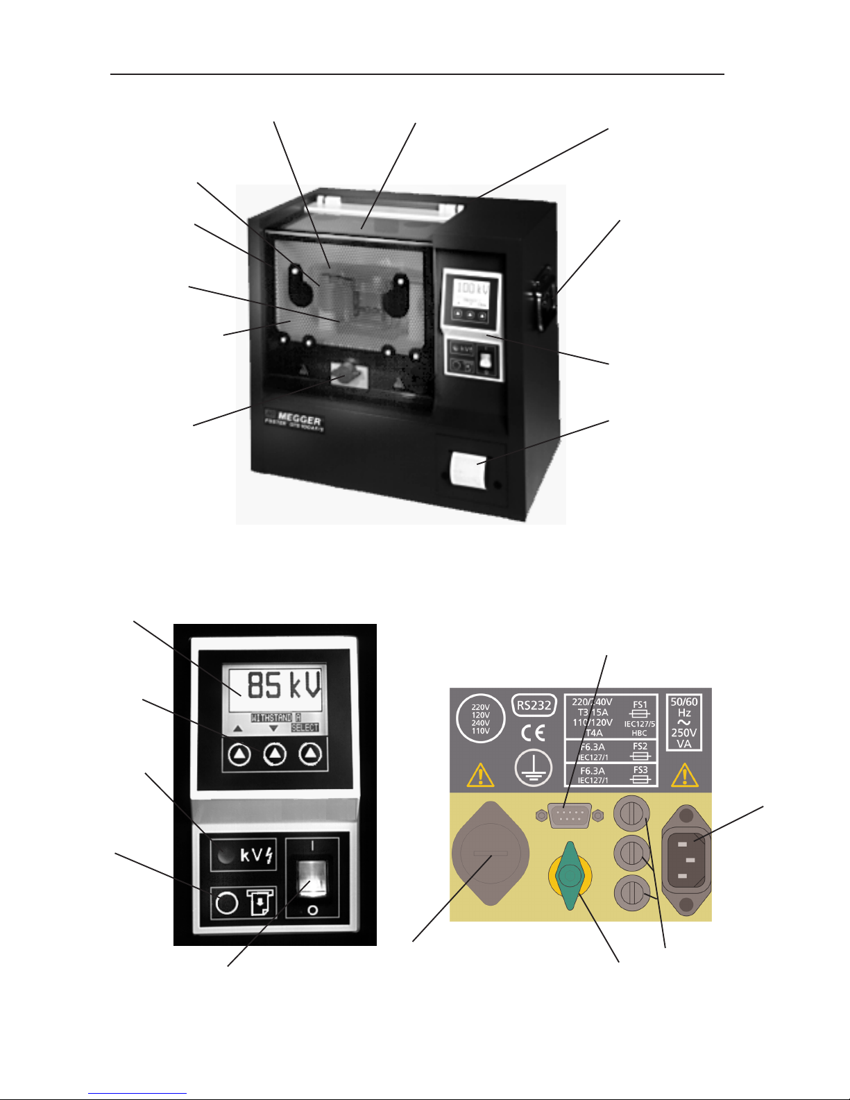
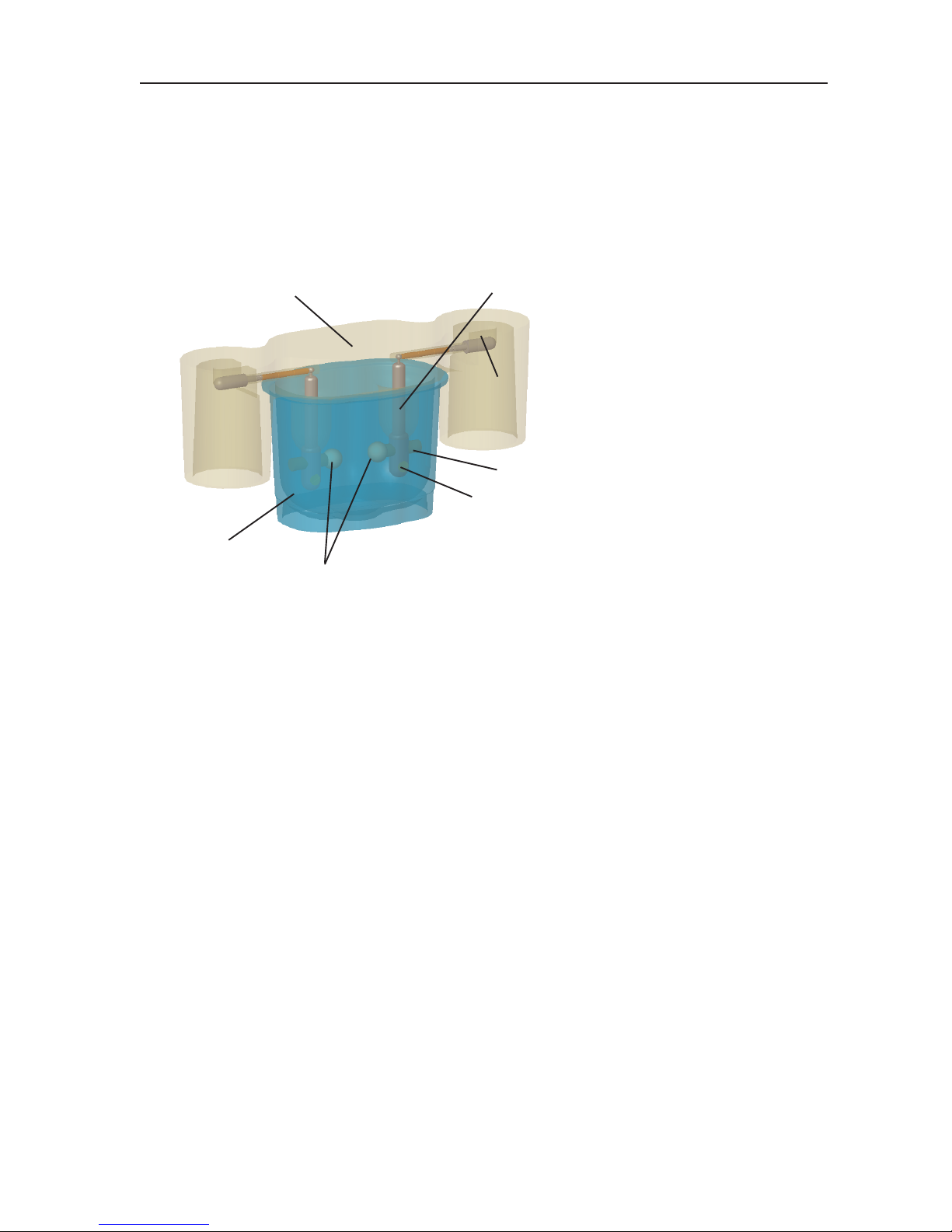
5
Cradle terminal
T
est chamber
Sheet steel case
Carrying handle
Control panel
Internal printer
H.V. transformer
output terminal
‘
horns’
E.M.C./ Discharge
barrier
Oil test vessel
Hinged
polycarbonate
cover
Safety
interlock on test
chamber
H.V. indicator
Printer paper
feed key
Liquid crystal
display
Control
keys
Power supply
On/Off switch
External printer
connector
Mains
supply
socket
Fuses
Mains supply
voltage selector
Earth terminal
(additional)
Figure 2. Oil test set controls etc.
Figure 1. OTS100AF/2 oil test set layout (the OTS80AF/2 and OTS60AF/2 are similar).
Figure 3. Oil test set rear panel.
Page 6
The OTS60AF/2, OTS80AF/2 and OTS100AF/2 are used for determining the dielectric strength of liquid
insulants, such as the insulating oils used in transformers, switchgear and other electrical apparatus.
They are transportable and suitable for laboratory use as well as testing on site. A four wheeled trolley is
available to assist with on-site transportation.
The test sets are fully automatic. The operator has simply to prepare the test vessel, load it with sample
o
il, place it in the test chamber, select the appropriate specification for the tests and then start the test
sequence. The test set carries out automatically (and if necessary unattended) the sequence of tests as
defined by the pre-selected national specification.
Oil testing specifications, for which the sets are pre-programmed, are as follows:-
International IEC 156 1995
British BS 5874:1980, BS148:1984,
BS 5730a:1979
American ASTM 1816-84a, ASTM D877
German VDE 0370/84
French NFC 27-22:1974
Italian CEI 10-1-1987
Spanish UNE21-309-89
Russian
ΓOCT 658-75
Rumanian STAS 286-81
South African SABS 555-1985
Australian AS 1767-1976
Institute of Petroleum IP 295/83
European EN60156 (1996)
For other specifications, five separate, fully programmable, custom test sequences are available which
can be stored within the non volatile memory (NOVRAM). A 5 minute test sequence is also provided so
that a user may quickly obtain an idea of the state of an oil sample.
Three types of withstand (proof) testing of an oil sample are available. The principle of these tests is to
subject the oil sample to a specified voltage for a defined length of time (1 minute) to see if it will
withstand that voltage. Withstand test ‘A’ and Withstand test ‘B’ incorporate a user definable initial stand
time period.
Safety features incorporated in the design include the safety interlock on the test chamber cover and an
easily operated mains supply On/Off switch. These ensure a high level of safety for operators, provided
the set is used in a responsible manner.
Applications
6
Power cord
If the power cord plug is not suitable for your type of socket outlets (receptacles), do not use an
adaptor. You should use a suitable alternative power cord, or if necessary change the plug by cutting
the cord and fitting a suitable plug. The colour code of the cord is:
Earth (Ground)
Y
ellow/Green
Neutral Blue
Phase (Line)
Brown
If using a fused plug, a 13 Amp fuse to BS 1362 should be fitted.
Note: A plug severed from the power cord should be destroyed, as a plug with bare conductors is
hazardous in a live socket outlet (receptacle).
Page 7
Output Voltage (max.)
OTS60AF/2 60 kV (30 kV - 0 - 30 kV)
OTS80AF/2 80 kV (40 kV - 0 - 40 kV)
OTS100AF/2 100 kV (50kV - 0 - 50 kV)
(high voltage test frequency is 61,8 Hz)
Display Dot-matrix liquid crystal display giving alphanumeric information
and kV test voltage.
Resolution 0,1 kV
Temperature Range
Operating 0°C to +40°C
Storage -40°C to +70°C (in accordance with BS 2011 part 2)
Humidity Range
Operating 80% RH at 40° C (non-condensing)
Storage 93% RH at 40° C, 95% RH at 25°C (in accordance with BS 2011
part 2 )
External Printer Socket 9 pin ‘D’ type plug for RS232C interface
Safety The test sets meet the requirements IEC 61010-1
E.M.C. In accordance with IEC 61326-1
Operational uncertainties Refer to www.megger.com
Supply Voltage 220 V ± 10%, 240 V ± 10%,
110 V ± 10%, 120 V ± 10%,
(four selectable values), 50 Hz / 60 Hz.
Fuses 2 x 6,3 A (F) ceramic HBC IEC 127/1, 20 mm x 5 mm
3.15 A (T) ceramic HBC IEC 127/5, 20 mm x 5 mm, for 220 V /
240 V
4 A (T) ceramic HBC IEC 127/5, 20 mm x 5 mm, for 110 V/120 V
Mains power cord fused plug: 13 Amp fuse to BS 1362
Dimensions 502 mm x 464 mm x 319 mm (193⁄4in x 181⁄4 in x 121⁄2 in approx.)
Weight 41 kg (90 lb) approx.
Cleaning Wipe disconnected test set with a clean cloth dampened with
Isopropyl Alcohol (IPA)
Specification
7
Page 8

8
Accessories
Supplied with Instrument Part Number
User Guide 6172-064
Mains power cord 25424-860
O
il test vessel fitted with spherical electrodes 12,7 mm diam. 6231-445
Oil test set preparation kit 6121-486
comprising:two magnetic stirrers
pair of cylindrical electrodes 1 inch diam.
pair of mushroom electrodes 36 mm diam.
*electrode spacing gauges for 1 mm (0,04 inch), 2 mm (0,08 inch),
2,5mm, 2.54mm (0,1 inch) and 4,0 mm (0,16 inch)
Protective cover 5340-334
Optional
Voltage calibration meter (0-100kV) OTS/VCM100
Oil test vessel fitted with mushroom electrodes 36 mm diam. 6231-447
Oil test vessel fitted with cylindrical electrodes 1 in diam. 6231-446
Oil test vessel for ASTM D1816 specification (motorised stirrer) 6111-146
A pair of mushroom electrodes 6220-482
A pair of cylindrical electrodes 6220-483
A pair of spherical electrodes 6220-484
A pair of cylindrical electrodes with 0,5 mm edge radius for use with any test vessel 6220-538
Printer paper 57,5 mm wide, 15 m long, 50 mm diam. 25995-001
Printer ribbon Epson part no. ERC-09 (IRC160) 25995-002
Printer lead, 9 pin female ‘D’ connector to 25 way male ‘D’ connector 25955-026
PC Download lead
25955-025
T
ransportation trolley
6320-224
Note:- Capacity of oil test vessels is 400 ml, except for the ASTM D1816 vessel which is 800 ml.
*
The new spacer gauges are no longer big enough to have the diameter marked on them.
They now
have a series of grooves cut into them to state the difference between them which is as follows:
1 rings - 1mm
2 rings - 2mm
3 rings - 2.5mm
4 rings - 4mm
Guage Indentification
5152-293
5152-294
5152-296 5152-319 5152-296
1mm 2mm 2.5mm 2.54mm 4mm
Rings
1
2
3
4
Page 9

Warnings
1. Ensure that the oil test set is properly earthed before use. The test set MUST be connected
to a socket outlet with a protective earth conductor. To ensure effective earthing, it is
recommended that the green/yellow terminal on the mains input panel at the rear of the test set
be separately connected to a known good earth.
2. Before connecting the mains supply, ensure that the mains supply voltage selector is set to the
correct value for the power supply to be used. The voltage selector is located on the mains input
panel at the rear of the test set.
3. Ensure that the test chamber is always scrupulously clean, particularly prior to a test. Wipe away
any spilled oil in the test chamber or on the test vessel when necessary.
The vessel must be properly positioned in the test chamber on the top of the support horns.
4. If the test chamber cover is cracked or damaged in any way, the test set
MUST NOT be used.
The cover must be replaced, by an authorised repairer, before the set is put into service again.
5. The oil test set has a metal emc/discharge barrier on the inside of the test chamber cover which
is connected via two springs to the earth pin of the mains supply input plug. The continuity
between the metal barrier and the earth pin must be routinely checked at weekly intervals. There
are also two touch contacts from the metal barrier on to the casing. The integrity of these
contacts should be verified when closing the cover.
6. The test set is fitted with high breaking capacity ceramic fuses to IEC 127. It is essential that any
replacement fuses fitted to the test set conform to this specification, (for full details see the
Specification section). Glass fuses
MUST NOT be used due to their low breaking capacity.
7. Only test vessels manufactured and supplied by Megger Limited for use with the OTS60AF/2,
OTS80AF/2 or OTS100AF/2 sets must be fitted within their respective test chambers.
The correct vessel type is shown in Figure 4. No other vessel or container, (including any which
may look similar) must be used.
8. Damage to the test set and loss of warranty may result from the use of the wrong oil test
vessels.
9. Casing panels or covers must not be removed while the test set is connected to the mains
supply
. T
o do so will expose live parts of the circuit. Internal capacitors may retain their charge
even when the test set is disconnected from the mains supply (especially under fault conditions).
Any adjustments or repair must be carried out by trained qualified personnel, therefore loss of
Warranty may result if work is carried out by personnel other than the manufacturer or one of his
approved agents.
10. Whenever it is likely that the test sets protection has been impaired, it must
NOT be used, but
taken out of service and returned to the manufacturer or his approved agent for repair.
The protection is likely to be impaired if, for example the test set shows visible signs of damage;
fails to perform the intended measurements; has been subjected to prolonged storage under
unfavourable conditions or has been subjected to severe transport stresses.
1
1.
If the oil test set has been exposed to severe environmental changes i.e. in humidity or
temperature, it should be allowed to acclimatise to its new conditions for a period of not less than
12 hours before use.
9
Page 10
Preparing the Test Vessel
1. Separate the cover holding the electrode mountings from the container.
2. Ensure that the vessel is thoroughly clean, both inside and out.
3
. Mount the appropriate electrodes on the sliding arms, if they are not already in place. It may be
necessary to slacken one or both of the clamp screws at the base of the electrode supports and
move the sliding arms back. The sliding arms have a threaded stud and the electrodes screw on
to these. Screw on and tighten firmly with finger pressure.
4. Set the gap between the electrodes according to the requirement of the testing specification
being undertaken. Spacing gauges are provided in the accessory kit for this purpose. The clamp
screws at the bottom of both electrode supports should be slackened and the sliding arms
moved so that the gap is approximately central between the two supports. Tighten the clamp on
one support to hold one side firmly, then adjust the other so that when the gauge is passed
between the electrodes it touches both simultaneously. Tighten the clamp screw on the second
support. Recheck the gap after it has been set.
A
list of electrode shapes and gap spacing for standard testing specifications is shown opposite.
Each test display screen also shows electrode shape; spacing, and type of stirring for each preprogrammed test specification, where appropriate.
5. Clean the vessel in accordance with the instructions given in the relevant test specification to be
used, then fill the container part of the vessel with the sample oil until the level is about 12 mm
(
1
⁄2 in) from the top.
6. If required, drop in a clean magnetic stirrer bar (not for ASTM D877 and ASTM D1816
specifications, or any case where impeller stirring has been selected). Ensure that the stirrer bar
is central in the vessel.
Note:- The
ASTM D1816 specification requires continuous stirring.
This is provided by the special
D1816 vessel by the motor driven impeller. See figure 12 on page 19.
7.
Carefully reassemble the two parts of the test vessel.
10
Operation
Figure 4. Oil Test Vessel
Electrode
support
Shrouded
connector arm
Container
Electrodes
Sliding arm
Clamp screw
Cover
Page 11
Loading the Test Vessel
1. Open the test chamber cover by turning the trapped key interlock knob a 1⁄4-turn anticlockwise
and pulling it outward.
2. Place the test vessel in the chamber so that the ends of the connector arms rest on the cradle
terminals at the top of the support horns. Clean away any spilled oil.
Note:- For an ASTM D1816 vessel connect the paddle stirrer motor lead to the supply socket in the top
rear of the test chamber.
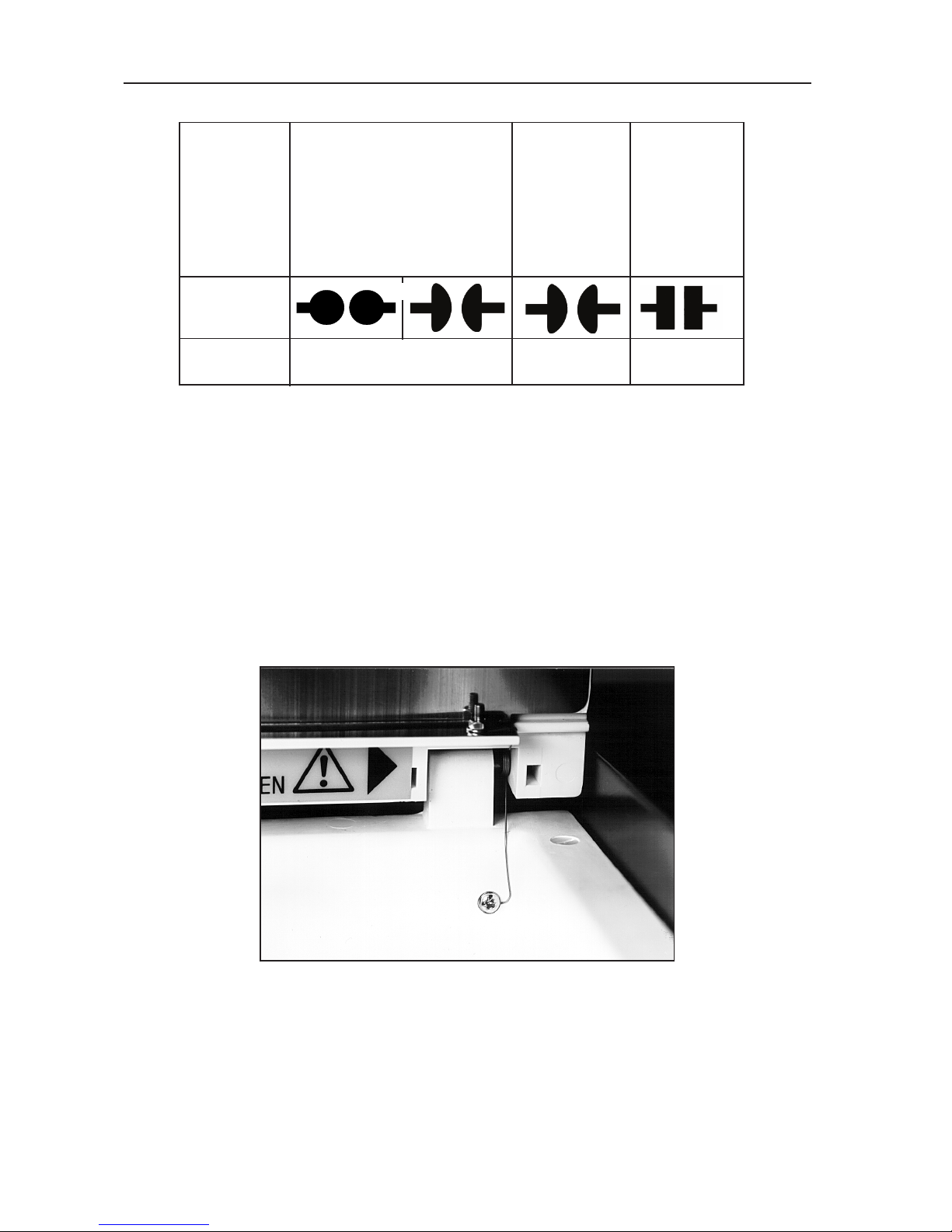
Caution:- Visually confirm that the two spring earth contacts linking the metal emc/discharge
barrier on the test chamber cover to the back of the chamber are intact (see Figure 5).
3. Close the test chamber cover, pushing in and turning the interlock knob clockwise to secure it.
11
S
tandard
test
specification
selected
Electrode
shape
Electrode
spacing
ASTM D1816
ASTM D877
2,5 mm
1 or 2 mm
2,54 mm
EN60156
AS 1767 BS148
BS 5874 CEI 10-1
IEC 156 IP 295
NFC 27 ΓOCT 6581
SABS 555 VDE 0370
UNE 21 STAS 286
OR
Figure 5. Spring earth contact on test chamber cover.
Page 12

Preparing the Oil Test Set
1. Adjust the mains voltage selector if necessary and connect the oil test set to a suitable supply. It
is recommended that the green/yellow earth terminal is connected to a known good earth.
2. Switch on both the supply and the test set. The copyright message appears on the display for a
b
rief time and is followed by the main programme menu screen. The options available from the
main menu are:-
AS 1767-1976
ASTM D877
ASTM D1816-84a
BS 148:1984
BS5730a:1979
BS 5874:1980
CEI 10-1-1987
EN60156 - 1996
IEC 156 1995
OPTIONS
IP 295/83
NFC 27-221: 1974
ΓOCT 6581-75
SABS 555-1985
STAS 286-81
UNE21-309-89
VDE 0307/84
5 MINUTE TEST
SELF CHECK
CHECK CALIBRATION
CUSTOM
WITHSTAND (PROOF)
The main menu display allocates labels to the three control keys, as their function changes. On switch
on, these will be (from left to right)
s, t, and SELECT. The left and centre keys control scrolling up and
down through the menu options, and the SELECT key activates the highlighted option.
Note:- The display shows only five menu options at any one time and those in view will depend upon
the last option used. When scrolling, the highlighted option is the one ready for selection.
3.
Select the required option and follow the display instructions.
Selecting OPTIONS from the main menu
The OPTIONS sub-menu allows you to set up and retain customised preferences for the following:-
DISPLAY CONTRAST
DISPLAY BACKLIGHT
LANGUAGE
PRINTER CONTROL
TIME / DATE
Note:- All of the settings will remain in the internal memory when the instrument is switched off or the
test chamber cover interlock switch is opened.
Scroll through and select as before. Highlight MENU and press SELECT
to return to the main menu.
Display Contrast
When DISPLA
Y
CONTRAST is selected, the centre and left arrow keys can be used to adjust the
readability of the display screen. Press SELECT to return to the OPTIONS sub-menu.
Note:- A quick way to bring the display contrast into view on the screen is to press the centre key while
switching the test set on. The key must be held for approx. 1 second after switching on.
Display Backlight
When DISPLAY BACKLIGHT is selected, the centre and left arrow keys can be used to switch the
display backlight ‘On’ or ‘Off’ as required. Press SELECT to return to the OPTIONS sub-menu.
12
Operation
Page 13

Language Select
The display screen and print-out can be set to read in any one of six languages:-
ENGLISH
FRANCAIS
DEUTSCH
E
SPANOL
PORTUGUES
ITALIANO
Scroll through and select as before. Pressing SELECT returns to the sub-menu.
Note:- A quick way to bring the language screen into view on the screen is to press and hold the right
hand key while switching the test set on. After making the selection proceed through the
remainder of the OPTIONS sub-menu.
Setting the printer options
Scroll through the OPTIONS sub-menu to PRINTER CONTROL and press SELECT.
A further sub-menu is displayed as follows:
PRINT LAST RESULTS
AUTO PRINT
NO. OF COPIES
BAUD RATE
QUIT
INT. PRINTER ON
EXT. PRINTER OFF
Where applicable, the status of each option is given (e.g. NO. OF COPIES 1), and this can be altered as
required by successive pressing of the SELECT key. For example, to change the ‘On’/‘Off’ mode of the
internal printer, scroll through this sub-menu to INT PRINTER, and press SELECT. It is expected that the
internal printer will normally be on.
Note:- Successive pressing of the SELECT key toggles the internal printer between the ‘On’ and ‘Off’
mode. This automatically switches the EXT PRINTER (external printer option) to the opposite
mode. It is not possible to use both the internal printer and an external printer together.
If an external printer is to be used, the Baud rate of the the test set must be adjusted to match that of the
printer. To do this, scroll through the menu until BAUD RATE is highlighted. Successive pressing of the
SELECT
key will scroll between standard Baud rates available i.e. 9600, 4800, 2400, 1200, 600, 300 and
150. Leave in view the one to be chosen. The data transfer format is:-
1 start bit
8 data bits
1 stop bit
no parity
One or two copies of the results print-out may be made. Scroll through to No. OF COPIES and press
SELECT to toggle between the selection of 1 or 2. Leave the required number displayed. The PRINT
LAST RESULTS option causes the last set of test results to be printed when the SELECT key is pressed.
Note:- The last set of test results remain in the internal memory when the instrument is switched off or
the test chamber cover interlock switch is opened.
The test set will automatically print the results
of a test when completed if the
AUT
O PRINT
option is set to ‘On’. Scroll through as before until
the option is highlighted and, if necessary, press SELECT until the required status is displayed.
If this option is set to ‘Off’ then a PRINT option will be given at the end of a test sequence.
To move back into the OPTIONS sub-menu scroll through until QUIT is highlighted, then press SELECT.
To move back to the main menu from the OPTIONS sub-menu scroll through until MENU is highlighted
and press SELECT.
TIME / DATE
The correct time and date are pre-set and will not normally need to be adjusted. The internal 24 hour
clock is powered by a LITHIUM battery with a life of 10 years.
13
Page 14

When TIME / DATE is selected, a further sub menu is displayed as follows:
DATE FORMAT
VIEW
QUIT
SET DATE
S
ET TIME
Scroll through and select as before.
DATE FORMAT offers the choice of U.K. date style (dd-mm-yy), or U.S. date style (mm/dd/yy).
Successive pressing of the SELECT key will select the alternate style.
To adjust the date, scroll to SET DATE, and press SELECT. Set the date with the left and centre arrow
keys, and press SELECT. Then set the month, followed by the day of the month, in the same way.
To adjust the time, scroll to SETTIME, and press SELECT. Set the hour with the left and centre arrow
keys, and press SELECT. Then set the minutes in the same way.
Selecting VIEW will display the time, together with date in the chosen format. To return to the sub menu,
scroll to highlight QUIT and press SELECT.
To return to the main menu, scroll to highlight MENU, and press SELECT.
Automatic Testing Sequences
Choose the appropriate pre-programmed oil testing specification programme from the main menu by
scrolling through using the s, t keys until the required specification is highlighted. Then press SELECT.
When a test specification has been selected in this way, the display screen changes to show the name of
the test (this remains in view throughout the test sequence) and gives an option to START the test
sequence with the left hand key, or return to the main menu with the right hand key. For each separate
test specification, the display will indicate appropriate choices of electrode shape and spacing, if the
specification stipulates these. The appropriate method of stirring is also shown. If the STIR MODE option
is displayed, the user may vary the mode of stirring between MAGNETIC (magnetic stirrer bar),
IMPELLER (stirrer test vessel), or NONE as is appropriate to the selected test.
When started, each test sequence is carried out completely automatically.
Note:- The microprocessor software contains routines which monitor the operation of the oil test set. In
the unlikely event of a problem occurring (whether caused by the test set or an external event),
the test currently in progress will, when resumed continue from the point at which the problem
occurred. If this is not possible the test set will be placed in a safe condition and a situation
status message will be displayed.
14
Operation
Calculations
After an automatic test sequence is completed, the average is calculated from the following formula:
A
verage
x =
n
∑
x
i
where
Standard Deviation
The sample standard deviation s(also known as σ
n-1
) is given by:-
s = ∑
x
i
2
-
n x
2
√
n - 1
Where s= sample standard deviation.
Data Dispersion
The ratio of standard deviation upon mean (
s / x )
also known as the co-efficient of variation is used to
determine whether the spread of a set of test results is within acceptable limits. This value may be
expressed as a percentage.
i = n
i = 1
1
x
= mean (average) of results
x
i
=i
th
individual results
n
= number of results
i = n
i = 1
Page 15
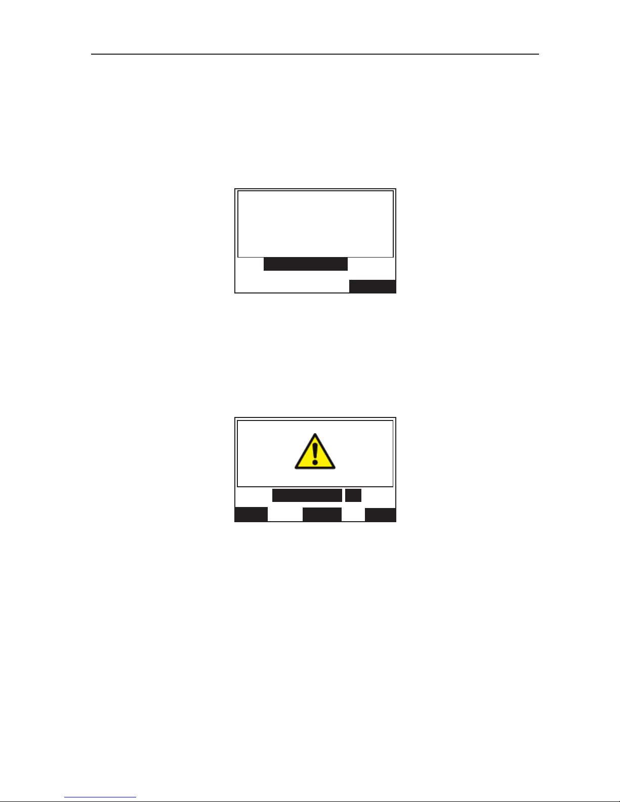
5 MINUTE TEST
Note:- This is a non-standard test, designed to provide a rapid assessment of the oil condition.
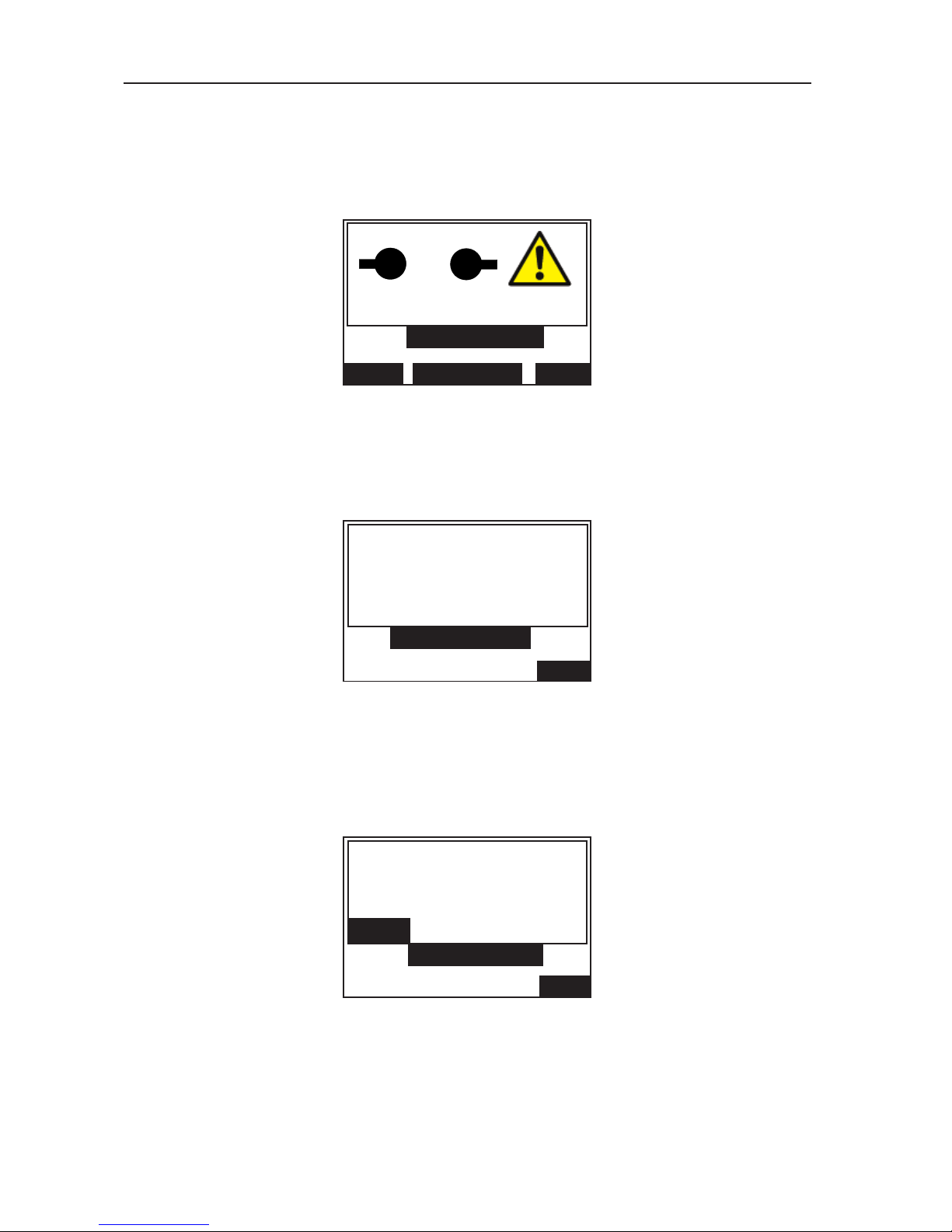
1. To commence the test, highlight 5 MINUTE TEST on the main menu and press select. The
display will appear similar to figure 6.
Repeated pressing of the centre key marked STIRMODEchanges the stirring choice through
MAGNETIC, IMPELLER or NONE. Press the right hand key marked MENU to return to the main
menu.
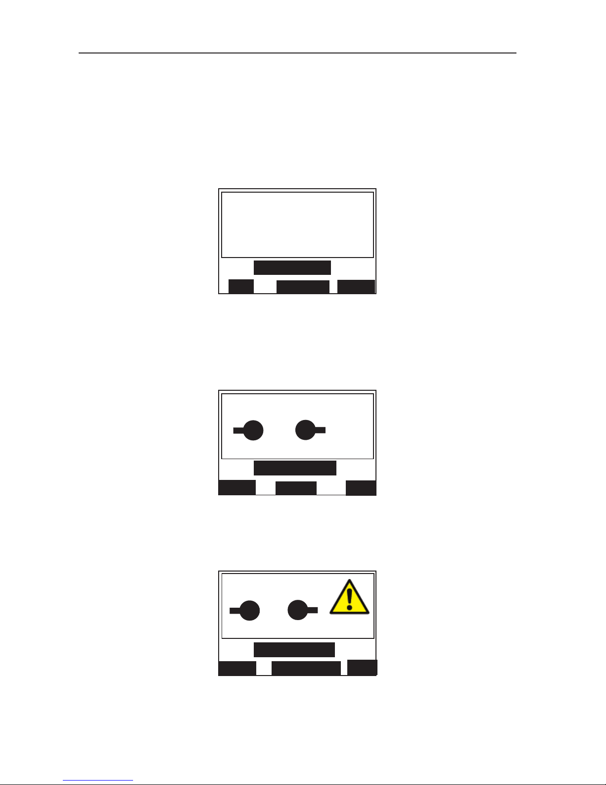
2. On pressing the START key the display appears similar to figure 7.
The display indicates that the one minute initial stand time is being undertaken, and the
remaining time is shown in seconds.
3. After the initial stand time is complete the high test voltage is automatically switched on and
applied to the sample. The display showing ‘TEST 1’ appears similar to figure 8.
The high voltage indicator light is illuminated, and the display shows the voltage rising at the rate
of 2kV/s being applied to the oil sample. This voltage rise continues until break down occurs (or
up to maximum). The number of the test in the sequence is displayed, together with the words
‘IN PROGRESS’.
Figure 8. Applied voltage display screen.
Figure 7. Initial stand time display screen.
15
TIME REMAINING
01:00
INITIAL STAND TIME
STOP
5 MINUTE TEST
XX kV
TEST 1
IN PROGRESS
STOP
5 MINUTE TEST
5 MINUTE TEST
STIR MODE
MENU
START
STIRRING: MAGNETIC
2.5
mm
Figure 6. Initial Stir Mode selection display screen.
Page 16
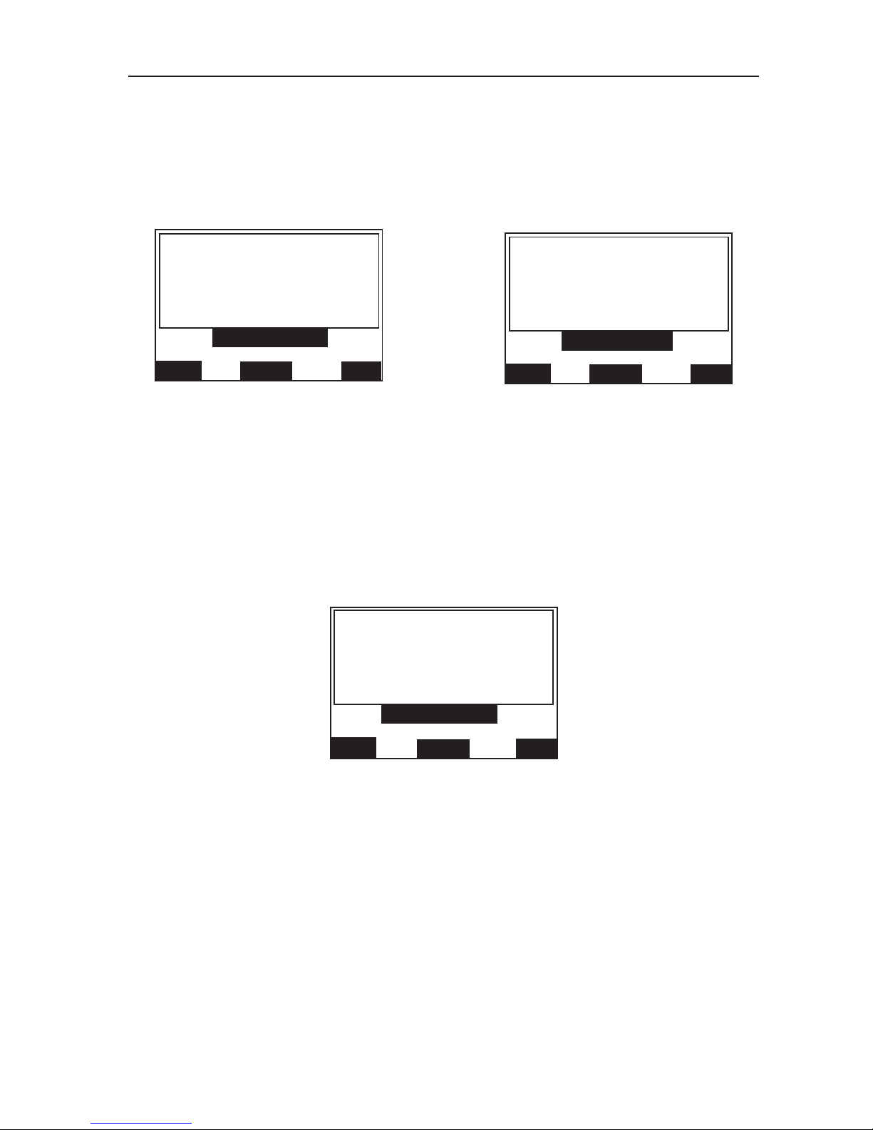
4. When breakdown occurs (or if the maximum voltage is reached) the test voltage is cut off, the
high voltage indicator light goes out and the test set begins its oil sample stirring period. The
stirrer rotates for a period of 30 seconds and the breakdown voltage value of the previous test is
retained on the display. The display screen appears similar to figure 9.
Stirring time remaining is shown, alternating with the word ‘STIRRING’.
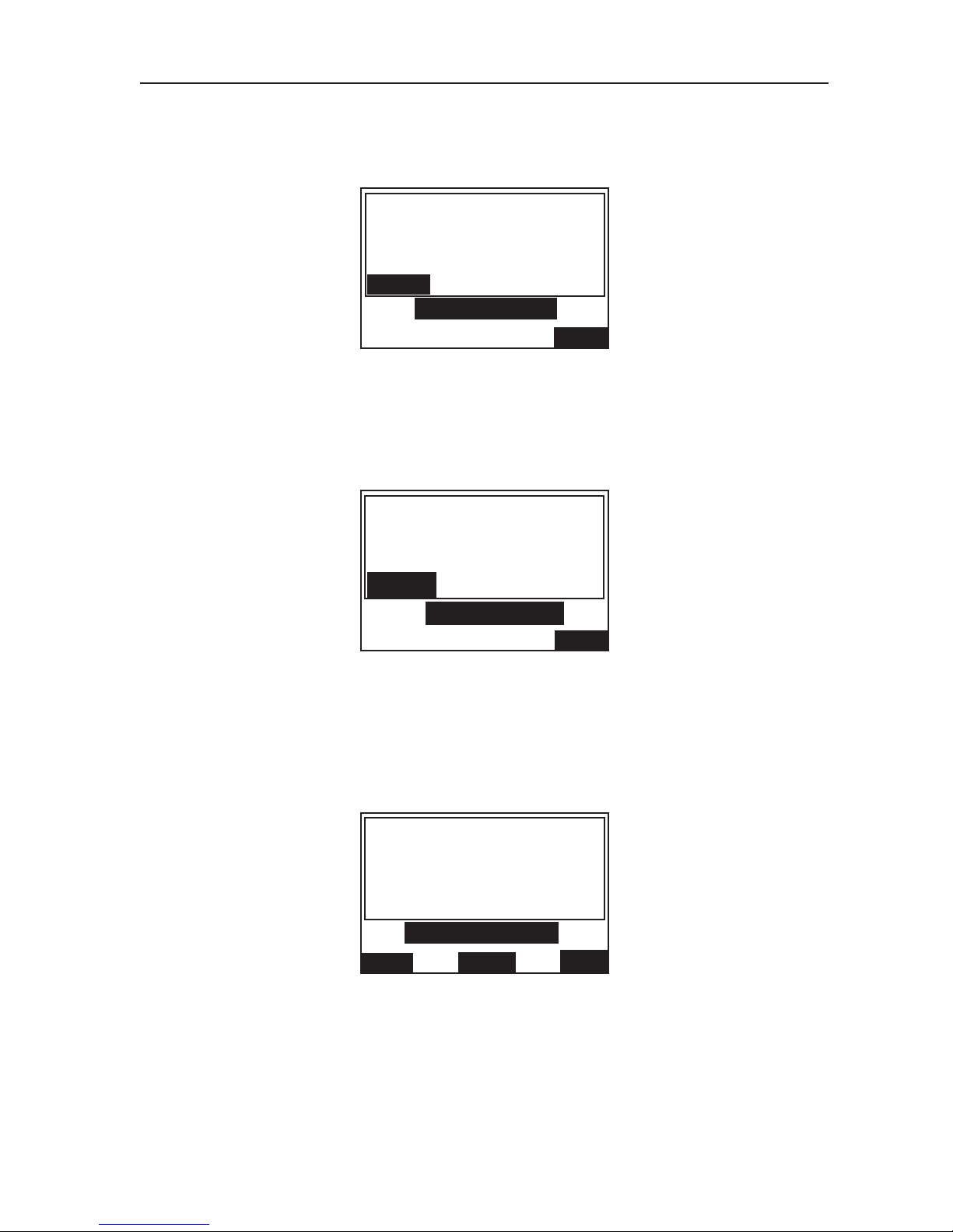
5. When stirring has finished the display indicates that the 30 seconds intermediate standing period
is being undertaken and time remaining is shown, alternating with the word ‘STANDING’. The
breakdown voltage is retained on the display, which appears similar to figure 10.
6. When step (5) is finished the test voltage then begins to rise again as in step (3), this time for
‘TEST 2’, and the cycle of events repeats.
7. Steps (3), (4), (5) and (6) are repeated so that the test voltage is applied for a third time. After
the test voltage has been cut of
f on the third test, the display shows the average breakdown
voltage value of the three tests in the sequence. The display appears similar to figure 11.
The three control keys now assume different functions. Press the left hand key labelled VIEW to
sequentially display the breakdown voltage value of each individual test, followed by their standard
deviation value. If the automatic print option is pre-selected, the results will be printed automatically at
the conclusion of a test sequence. If not, press the centre key, labelled PRINT to obtain a print-out of
the results. When the printer is in operation, the display shows ‘PRINTING PLEASE W
AIT’.
Press the NEW key to return to the start of the 5 MINUTE test, followed by the left hand START key to
repeat a test sequence, or the MENU key to return to the main menu.
Figure 9. Stirring mode display screen.
Figure 10. Intermediate stand time display screen.
Figure 11.
Average breakdown voltage display screen.
16
Operation
XX kV
TEST 1
5 MINUTE TEST
00:30
STOP
XX kV
TEST 1
STANDING
5 MINUTE TEST
STOP
XX kV
5 MINUTE TEST
AVERAGE VOLTAGE
VIEW
PRINT
NEW
Page 17

Note:- At any time during a test sequence the right hand control key labelled STOP can be used to end
a test and return to the test option display screen. Similarly during printing the left hand key
labelled STOP can be used to stop the print function and return to the average breakdown
display screen.
AS 1767, BS 148, BS 5874, CEI 10-1, EN60156, IEC 156, IP 295, NFC 27, ΓOCT 6581, SABS 555,
S
TAS286, UNE 21 and VDE 0370 tests.
Note:- These specifications give the option of using spherical or mushroom shaped electrodes.
1. To commence, highlight the selected test on the main menu and press SELECT. The display will
appear similar to figure 6. Press the right hand key marked MENU to return to main menu.
Repeated pressing of the centre key labelled STIR MODE changes the stirring choice through
MAGNETIC, IMPELLER or NONE.
2 On pressing the START key, TEST 1 is initiated. The display appears similar to figure 7. The
display indicates that the initial stand time is being undertaken and time remaining is shown in
minutes and seconds.
3. After the initial stand time is complete the high voltage is switched on and applied to the oil
sample. The screen display appears similar to figure 8.
The display shows the voltage rising at the rate of 2kV/s being applied. This voltage rise
continues until breakdown occurs (or up to maximum). The number of the test in the sequence is
displayed together with the words ‘IN PROGRESS’.
4. When breakdown occurs (or if the maximum voltage is reached) the test voltage is cut off, the
high voltage indicator light goes out and the test set begins its intermediate stirring period. The
stirrer rotates for a period of 1 minute and the previous breakdown voltage is retained on the
display. The display screen appears similar to figure 9.
Time remaining for stirring is displayed, alternating with the word ‘STIRRING’, unless stirring is
continuous (see page 7).
5. When stirring has finished the display indicates that the intermediate standing period is being
undertaken. Time remaining is shown, alternating with the word ‘STANDING’. The previous
breakdown voltage is retained on the display, which appears similar to figure 10.
6. The test voltage then begins to rise again as in step (2), this time for TEST 2, and the cycle of
events repeats.
7.
For these specifications there are 6 consecutive tests.
After the test voltage has been cut off on
the last test, the display shows the average breakdown voltage value from the 6 tests in the
sequence. The display appears similar to figure 11.
Note:- (1) NFC27, STAS286 and UNE21 test specifications differ from the above in that the last 5 of the
6 results are used to calculate the average and standard deviation. (2) The programme for the
BS 148 test sets a pass limit of 30 kV
, as required by the specification for this standard.
The three control keys now assume different functions. Press the left hand key labelled VIEW to
sequentially display the breakdown voltage value of each individual test, followed by their standard
deviation value. If the automatic print option is pre-selected, the results will be printed automatically at
the conclusion of a test sequence. If not, press the centre key
, labelled PRINT
to obtain a print-out of the
results. When the printer is in operation the display shows ‘PRINTING PLEASE W
AIT’. Press the NEW
key to return to the start of the selected test, followed by the left hand START key to repeat a test
sequence, or the MENU key to return to the main menu.
Note:- At any time during a test sequence pressing the right hand key labelled STOP will end a test and
return to the test option display. Similarly during printing, the left hand key labelled STOP can be
used to stop the print function and return to the average breakdown display screen.
17
Page 18

ASTM D877 test
Note:- This specification does not require stirring. Do not fit a magnetic stirrer bar.
1. To commence the test, highlight ASTM D877 on the main menu and press SELECT.
T
he display will appear similar to figure 7.
2. On pressing the START key, TEST 1 is initiated and the display appears similar to figure 7.
The display indicates that the 2 minute 20 second initial stand time is being undertaken, and time
remaining is shown. After the initial stand time is complete the high voltage is switched on and
applied. The display appears similar to figure 8.
The high voltage indicator light is illuminated, and the display shows the voltage rising at the rate
of 3 kV/s being applied. This voltage rise continues until breakdown occurs (or up to maximum).
The number of the test in the sequence is displayed together with the words ‘IN PROGRESS’.
3. When breakdown occurs (or if the maximum voltage is reached) the test voltage is cut off, the
high voltage indicator light goes out and the display indicates that the 1 minute intermediate
standing period is being undertaken. Time remaining is displayed, alternating with the word
‘STANDING’. The previous breakdown voltage is retained on the display, which appears similar
to figure 10.
4. When the intermediate stand time has finished the test voltage begins to rise again as in step
(2), this time for TEST 2, and the cycle of events repeats.
5. For this specification there are 5 consecutive tests. After the test voltage has been cut off on the
last test, the display shows the average breakdown voltage value of the 5 tests in the sequence.
The display appears similar to figure 11.
The three control keys now assume different functions. Press the left hand key labelled VIEW to
sequentially display the breakdown voltage values of each individual test, followed by their
standard deviation value.
If the automatic print option is pre-selected, the results will be printed automatically at the
conclusion of a test sequence. If not, press the centre key, labelled PRINT to obtain a print-out of
the results. When the printer is in operation the display shows ‘PRINTING PLEASE WAIT’.
Press the NEW key to return to the start of the
ASTMD877 test followed by the left hand STAR
T
key to repeat a test sequence or the MENU key to return to the main menu.
Note:- At any time during a test sequence, pressing the right hand control key, labelled STOP will end a
test and return to the test option display. Similarly during printing the left hand key labelled STOP
can be used to stop the print function and return to the average breakdown display.
ASTM D1816 test
Note:- This test requires continuous stirring by a paddle type stirrer, using the special vessel available
for this specification. See figure 12. The test can be performed with standard oil test vessels but
this will not conform to the specification. The magnetic stirrer may be selected if required. The
paddle stirrer is connected to the socket in the rear of the test chamber at the time the test
vessel is placed on the high voltage horns.
1. To commence the test, highlight ASTM D1816-84a on the main menu and press SELECT. The
display will appear similar to figure 6. Repeated pressing of the centre key labelled STIRMODE
changes the stirring choice through MAGNETIC, IMPELLER or NONE. Press the right hand key
labelled MENU to return to the main menu.
2. On pressing the START key, TEST 1 is initiated and the display appears similar to figure 7.
If selected, the stirrer operates and continues to do so throughout the test sequence.
The display indicates the stirring mode selected and that the 3 minute initial stand time is being
undertaken. Initial stand time remaining is shown in minutes and seconds.
18
Operation
Page 19

3. After the initial stand time is complete the high voltage is switched on and applied to the
oilsample. The display appears similar to figure 8.
The high voltage indicator light is illuminated, and the display shows the voltage rising at the rate
of 0,5 kV/s being applied. This voltage rise continues until breakdown occurs (or up to
maximum). The number of the test in the sequence is displayed together with the words ‘IN
PROGRESS’.
4. When breakdown occurs (or if the maximum voltage is reached) the test voltage is cut off, the
high voltage indicator light goes out and the display indicates that the 1 minute intermediate
stirring period is being undertaken. Stirring time remaining is shown in seconds, alternating with
the word ‘STIRRING’. The previous breakdown voltage is retained on the display, which appears
similar to figure 9.
5. When the intermediate stir time has finished the test voltage begins to rise again as in step (3),
this time for TEST 2, and the cycle of events repeats.
6. For this specification there are 5 consecutive tests. After the test voltage has been cut off on the
last test, the display shows the average breakdown voltage value from the 5 tests in the
sequence. The display appears similar to figure 11.
The three control keys now assume different functions. Press the left hand key labelled VIEW to
sequentially display the breakdown voltage value of each individual test, followed by their
standard deviation value.
If the automatic print option is pre-selected, the results will be printed automatically at the
conclusion of a test sequence. If not, press the centre key, labelled PRINT to obtain a print-out of
the results. When the printer is in operation, the display shows ‘PRINTING PLEASE W
AIT’.
Press the NEW key to return to the start of the ASTM D1816 test, followed by the left hand
START key to repeat a test sequence or the MENU key to return to the main menu.
Note:- At any time during a test sequence, pressing the right hand key labelled STOP will end a test
and return to the test option display
. Similarly during printing the left hand key labelled ST
OP
can be used to stop the print function and return to the average breakdown display.
Figure 12. Oil test vessel for ASTM D1816 specification.
19
Page 20

CUSTOM Test
This option is included so that users can program their own test parameters. Custom test is therefore
ideal for setting up other oil testing specifications. Up to five separate CUSTOM tests can be
programmed, and once established are stored in memory for use on future occasions.
P
rogramming a CUSTOM test
1. From the main menu select CUSTOM. The display will appear similar to figure 13.
The three control keys have the functions NEXT, SELECT and MENU.
Pressing the NEXT key moves on to the next (of the 5 available) CUSTOM tests.
Pressing MENU moves back to the main menu. Pressing SELECT moves into the programming
and testing options for that particular CUSTOM test. The control key functions changes to
START, PROGRAM and QUIT. Pressing QUIT moves back to the previous display. Pressing
START initiates a test sequence based upon the parameters displayed. Pressing PROGRAM
enables the test parameters to be altered.
2. To alter the test parameters, press the centre key labelled PROGRAM. The function of the three
control keys now become CHANGE, PRINT and QUIT. Pressing QUIT moves back to the
previous sub-menu and pressing PRINT provides a print-out of the test parameters in view on
the display.
3. Press the left hand CHANGE key to enter the sub-menu for setting the INITIAL STAND TIME.
Use the left and centre keys to decrease and increase respectively, the minutes and seconds
shown on the display
. Press SELECT when the desired value is set on the display; this makes
the selection and moves into the sub-menu for the next parameter to be set.
Note:- Repeated presses of a key changes the value in 5 second steps. Pressing and holding a key
changes the value in 5 second steps to the next minute value and thereafter in 1 minute steps.
(Maximum value 99 minutes 55 seconds).
4. The number of individual tests in a sequence may now be set; again using the the left and centre
keys to make the selection. Press SELECT
when the desired value is displayed; this makes the
selection and moves into the sub-menu for the next parameter to be set.
Note:- Repeated presses of a key changes the value in steps of one. Pressing and holding a key
changes the value in steps of one to the next five values and thereafter in steps of five.
(Maximum value 99).
5. The rate of rise of the test voltage may now be set; again use the left and centre keys to set the
desired rise rate and press SELECT when the desired value is displayed.
Note:- A press of a key changes the value by 0,5 kV/s and there is no rapid change facility. (Maximum
value 5 kV/s).
6. The display now changes to offer oil stirring options. Repeated pressing of the centre key
marked MODE changes the stirring choice through MAGNETIC, IMPELLER, or NONE.
If NONE is selected, there will be no intermediate stir. Repeated pressing of the left hand key
marked CONT. turns continuous stirring ‘On’ or ‘Off’. If CONT. is selected, there will be no
intermediate stand. Press SELECT
when the desired options are showing on the display
.
Figure 13. CUSTOM Test display screen.
20
Operation
NO. OF TESTS 1
RISE RATE 2:0
STIR TIME 0:30
STAND TIME 0:45
CUSTOM TEST
NEXT
SELECT
MENU
Page 21

7. If selected, the intermediate stir time between 0 seconds and 99 minutes 55 seconds may now
be set on the display. Increment to the desired time using the left and centre keys and press
SELECT.
8. If selected, the intermediate STAND TIME between 0 seconds, and 99 minutes 55 seconds may
now be set on the next display. Increment to the desired time using the left and centre keys, and
p
ress SELECT.
9. The average start number may now be set by operating the left and centre keys.
Note:- The arrow keys increment to set the number of tests to be used in calculating the average
breakdown voltage and standard deviation. The averaging of the breakdown voltages will start
from the number set. For example, if 1 was set all the results will be used to calculate the
average. If 3 was set then the first two breakdown voltage values will be ignored when the
average is calculated.
10. Press the SELECT key to set the average start and move out of the set-up mode. The
parameters that have been set for the CUSTOM test are now displayed. Press the QUIT key to
move back to the sub display giving the option to START a test, or press QUIT again followed by
NEXT to enable another CUSTOM test sequence to be set.
Performing a CUSTOM test
1. Obtain the START option and press the key. The oil test set will now automatically perform a
sequence of individual tests according to the customised programme. The average value and
standard deviation will be given at the end, together with the options to review and print the
results.
2. Pressing the NEW key followed by the QUIT and then the MENU key is the route back to the
main menu.
WITHSTAND (PROOF) TESTS
There are three types of Withstand (proof) test available. Following an optional, selected stand time, the
tests subject the oil sample to a selected withstand voltage for one minute, to see if breakdown occurs.
Withstand test ‘A’ causes the voltage to rise to a set value, remain there for one minute and then be
removed (if breakdown does not occur beforehand).
W
ithstand test ‘B’
causes the voltage to rise to a set value, remain for one minute and then be further
increased to maximum or the breakdown point whichever occurs sooner.
BS5730 test causes the voltage to rise to 22kV, 30kV or 40kV (depending on the selected installation
category and electrode gap) for 1 minute. If breakdown occurs, another 2 tests are automatically carried
out. Both these tests must pass for the sample to be accepted.
Withstand test ‘A’
1. From the main menu select the WITHSTAND option. On the display the function of the three
control keys changes to A, B and MENU. (Pressing MENU returns to the main menu options screen).
2. Press the left hand key labelled A. The display changes to appear similar to figure 14.
Figure 14. Withstand test initial stand time selection display screen.
21
INITIAL
STAND TIME
00:30
ENABLED:YES
WITHSTAND A
YES/NO
SELECT
s t
Page 22
Initial stand time is displayed. Repeated pressing of the left hand key changes ENABLED: to
YES or NO. To accept the displayed initial stand time, choose YES and press SELECT. To alter
the displayed initial stand time, press the centre arrows key. The display then moves to a sub
display to alter and set the initial stand time between 0 seconds and 99 minutes 55
seconds.Increment to the desired time using the left and centre keys, and press SELECT.
N
ote:-Repeated presses of a key changes the value in 5 second steps. Pressing and holding a key
changes the value in 5 second steps to the next minute value and thereafter in 1 minute steps.
3. The display now changes to show the Withstand voltage level and allow it to be altered as
required. The display appears similar to figure 15.
Use the left and centre keys to increase or decrease the withstand test voltage to the required
level.
Note:- Repeated individual presses of a key changes the value in 1 kV steps. Pressing and holding a
key changes the value in 1 kV steps to the next 5 kV value and thereafter in 5kV steps.
4. Press SELECT to move to the test option display as shown in the example of figure 16
5. The QUIT option moves back to the withstand test choice display.
6. Press and hold the STIR key to stir the oil sample if required.
7. Press the START key to begin a test. The test voltage will increase at 2 kV/s to the level set and
remain there for 1 minute (unless breakdown occurs first). The display shows the time for which
the voltage is applied.
8. The test voltage is automatically removed after 1 minute and the result of the test displayed.
Options are now displayed to PRINT the result or to perform a NEW test.
9. Press NEW to go back to the test option screen ready for a repeat test. From this option press
QUIT followed by MENU to return to the main menu.
Figure 16. W
ithstand test option display screen.
Figure 15. Withstand test voltage level display screen.
22
Operation
WITHSTAND
STIR
START
QUIT
A
30kV
WITHSTAND A
SELECT
st
Page 23
Withstand test ‘B’
Follow the procedure for Withstand test ‘A’, but note that after the test voltage has been maintained for 1
minute it will continue to rise at 2 kV/s to the breakdown point or to the maximum value, before it is
automatically removed.
BS5730a test
1. With reference to BS 5730a, adjust and set the appropriate electrode gap of 2,5mm or 4,0mm.
2. From the main menu highlight and select BS5730a. The display will appear similar to figure 17.
3. Pressing MENU moves to the main menu. With reference to BS 5730a, select the appropriate
EQUIPMENT CATEGORY by pressing the left or centre key.
4. The display now changes to appear similar to figure 18. Press the left or centre key to select the
electrode gap setting of either 2,5mm or 4,0mm. Pressing QUIT returns to the previous sub
display.
5. The display will now change to show the correct withstand voltage together with the selected
electrode gap. Assuming that the 2,5mm key was operated, the display would appear similar to
figure 19.
Repeated pressing of the centre key marked STIR MODE changes the choice of stirring through
MAGNETIC, IMPELLER or NONE. Pressing QUIT returns to the previous sub menu.
Figure 17. BS5730a Equipment Category selection display screen.
Figure 18. BS5730a electrode gap selection display screen.
Figure 19. BS5730a Test start display screen.
23
BS 5730a: A, D
QUIT
2.5mm
4.0mm
SELECT GAP
BS 5730a: A, D
QUIT
VOLTAGE: 30kV
START STIR MODE
STIRRING: MAGNETIC
2.5
mm
?
mm
?
mm
BS5730a:1979
SELECT
EQUIPMENT
CATEGORY
A, D
B, C, E, F
MENU
Page 24
6. On pressing the START key, the automatic test sequence is initiated, and the voltage is
displayed ramping up to the withstand voltage level. Pressing the right hand key labelled STOP
will abort the test, and return to the original display. On successfully attaining the upper voltage
limit, the display will appear similar to figure 10. Elapsing time (in seconds) is indicated, until 1
minute has elapsed, or breakdown has occurred.
7
. The sequence of events now depends on the results of the first test. If the test was successful
no further testing takes place. The display appears similar to figure 20.
8. If the first test fails the requirements of BS 5730a, two further consecutive successful tests
mustbe performed. Prior to the repeat withstand voltage application, a 1 minute stir followed by a
1 minute stand period is automatically performed.
9. The second application of the withstand voltage will automatically occur next, with the sequence
repeating step (6) above. The display will indicate the actual test number in progress.
10. The sequence of events now depends on the result of the second test. If the second test is
unsuccessful, no further testing takes place.The display appears similar to figure 21.
Pressing the left hand key labelled VIEW changes the top half of the display to show the break
down voltages, together with the pass limit voltage. The display appears similar to figure 22.
If the automatic print out option is pre-selected, the results will be automatically printed. If not,
press the centre key labelled PRINT
to obtain a print out of the results. When the printer is in
operation, the display shows ‘PLEASE WAIT PRINTING’.
1
1.
If the second test was successful, a third test must be performed. Prior to the repeat withstand
voltage application, a 1 minute stir followed by a 1 minute stand period is automatically
performed.
12. A third application of the withstand voltage will occur next, with the sequence repeating step (9)
above.
The display indicates the actual test number in progress.
13. If the third test was successful, the display will appear similar to figure 20. An unsuccessful third
test will prompt a display similar to figure 21, and no further testing takes place.
Figure 20. BS5730a PASS-FAIL display screens. Figure 21.
Figure 22. BS5730a Results display screen.
24
Operation
PASS LIMIT: 30kV
PASS
GAP: 2.5mm
BS 5730a: A, D
VIEW
PRINT
NEW
TEST 1: 28.6kV
TEST 2: 26.3kV
PASS LIMIT: 30kV
BS 5730a: A, D
VIEW
PRINT
NEW
PASS LIMIT: 30kV
FAIL
GAP: 2.5mm
BS 5730a:A, D
VIEW
PRINT
NEW
Page 25

14. On completion of the test(s) (1, 2 or 3 may have been performed), the appropriate PASS or FAIL
message is displayed. Pressing the right hand key labelled NEW returns to the EQUIPMENT
CATEGORY selection display screen. Pressing the left hand key labelled VIEWchanges the top
half of the display to list the breakdown voltage(s), together with the pass limit voltage. The
display appears similar to figure 22.
I
f the automatic print out option is pre-selected, the results will be automatically printed. If not,
press the centre key labelled PRINT to obtain a print out of the results. When the printer is in
operation, the display shows ‘PLEASE WAIT PRINTING’.
Note:- At any time during a test sequence, pressing the right hand key labelled STOP will end a test
and return to EQUIPMENTCATEGORY selection display. Similarly during printing the left hand
key labelled STOP can be used to stop the print function and return to the test result display.
SELF CHECK Tests
The SELF CHECK option enables the following parts of the circuit to be checked:-
NOVRAM (Non Volatile Random Access Memory)
KEYBOARD
DISPLAY CONTRAST
DISPLAY BACKLIGHT
TIME / DATE
PRINTER (Internal and External)
STIR
RISING VOLTAGE
WATCHDOG TIMER
Note:- It is not necessary to have the oil test vessel filled with sample oil for the SELF CHECK tests,
but a vessel with a stirrer is necessary.
1. From the main menu select the SELF CHECK option. The first display to appear gives a warning
that a NOVRAM test will clear the memory. The option keys take the labels YES; NO and QUIT.
Pressing the QUIT key returns you to the main menu.
Caution:- If the YES button is pressed, the NOVRAM memory will be cleared. This will
include the parameters set up for CUSTOM and WITHSTAND tests as well as any
results data. If this information is needed then the YES button must NOT be
pressed.
2. Pressing the NO key bypasses the NOVRAM test and moves straight to the KEYBOARD test.
Press the left arrow key and then the right hand key
. When pressed, each key displays its
number to indicate that it is active.
3. The DISPLAY CONTRAST test is now presented, and a grid appears on the display. The left and
centre arrow keys can be used to increase or decrease the display contrast. Press SELECT to
move on to the DISPLAY BACKLIGHT test. Use the left and centre arrow keys to turn the light
‘On’
and ‘Of
f
’.
4. Press the SELECT key and the current TIME and DATE will be displayed and checked. If all is in
order, the message ‘TESTPASSED’ will be displayed.
5.
Pressing the NEXT
key brings into effect a PRINTERS test. The internal printer is checked, and
then the external printer (if fitted).
The option to ST
OP
the test is given.
6. Pressing the NEXT key starts the STIRRING TEST which lasts for one minute, and is
automatically followed by the RISING VOL
T
AGE test. (Options to RETEST or NEXT are given).
7. Before the screen automatically returns to the main menu, a WATCHDOG test is performed. The
WATCHDOG TIMER ensures that the microprocessor is constantly running.
25
Page 26
Calibration Check
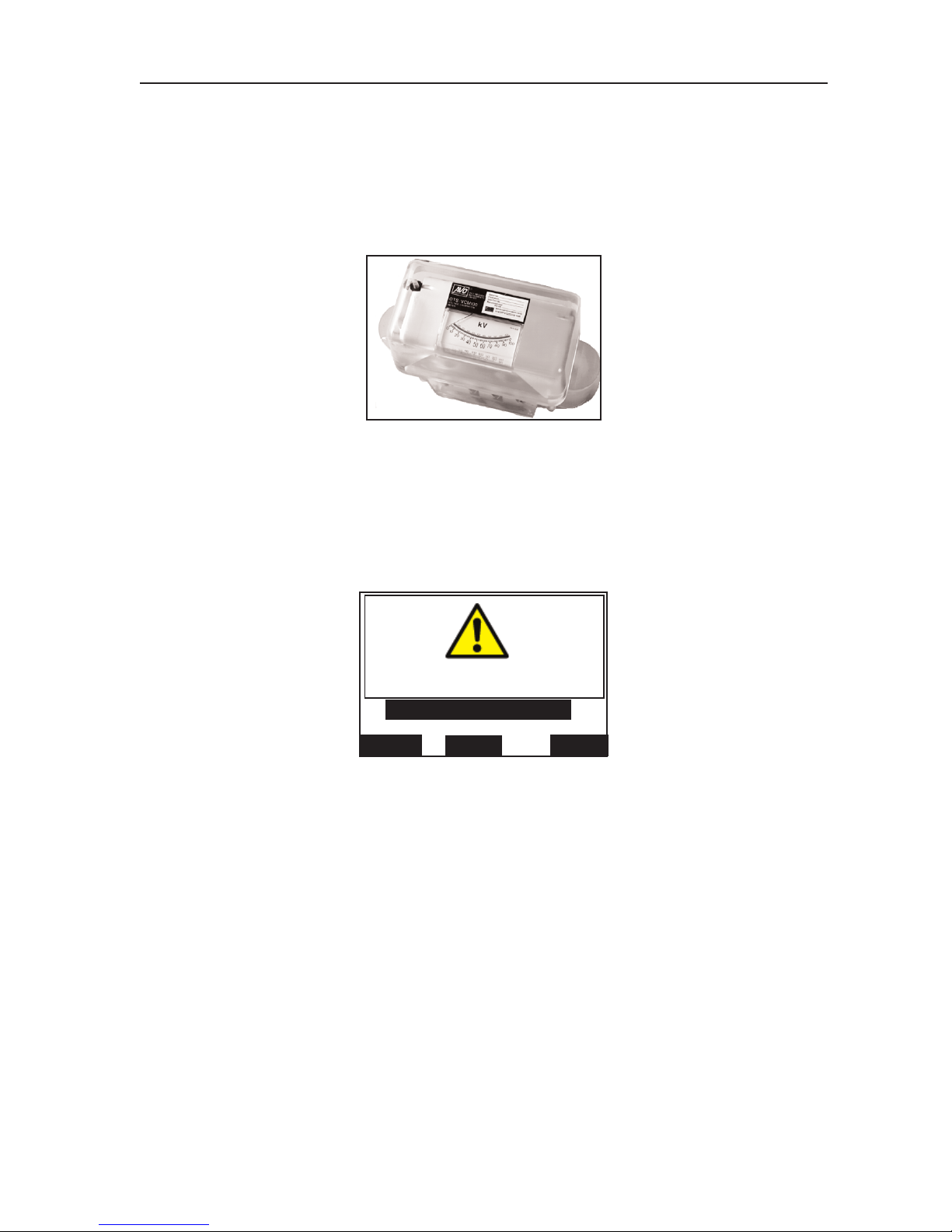
The optional OTS/VCM100 calibrator provides the means to carry out a quick calibration check of the
test set high voltage output. The calibrator fits onto the test chamber cradle terminals in place of a test
vessel, and voltage indication is viewed on an analogue meter marked from 0 to 100kV in 2kV divisions
(accuracy 3%).The scale also shows pass tolerance bands to enable a quick assessment of the
a
ccuracy to be made. The design ensures that the load to the test set transformer is similar to the load
during an oil dielectric strength test.
Using the OTS/ VCM100
1. Place the VCM100 on the cradle terminals at the top of the support horns.
2. From the main menu select CHECK CALIBRATION. The display will appear similar to figure 24.
3. If a hard copy of the test results is required, press the centre key marked PRINT to obtain a
calibration check list. This enables the user to manually record the calibrator readings as the test
proceeds. When the printer is in operation, the display shows ‘PRINTING PLEASE WAIT’.
4. On pressing START, the check sequence is initiated. The voltage ramps up from 0kV to the
maximum voltage value, pausing at each 10kV point for a period of 10 seconds. This enables
the oil test set indicated voltage to be verified against the calibrator.
Note:- At any time during a test sequence the right hand control key labelled ST
OP
can be used to
enda test and return to the first screen display
.
5. If required, write down each analogue reading on the print out check list.
6. Press the right hand key marked MENU to return to the main menu.
Figure 23. OTS/VCM100 Calibrator.
Figure 24. OTS/VCM100 Calibrator.
26
Operation
CHECK CALIBRATION
MENU
PRINT
START
USE OTS/VCM 100
Page 27
Printer Facilities
Paper feed key
The printer paper feed key, situated adjacent to the On/Off switch, may be pressed at any time (when the
test set is switched on) to advance the paper roll.
Replacing a printer paper roll
Do not replace the printer paper roll while a test is being conducted.
1. Remove the printer cover by releasing its two fasteners, by giving them each a 1/4 turn.
2. Remove what remains of the old paper roll, noting where the paper feeds into the printer head,
and place a new roll into the roll tray.
3. Keeping the edge of the paper ‘sharp’ and straight, feed the end of the paper through the printer
head. It slots in at the bottom just behind the ribbon carrier. Use the paper feed key to advance
the paper through the printer head.
4. Feed the paper through the slot in the printer cover then replace the cover and secure its
fasteners by giving them a 1/4 turn.
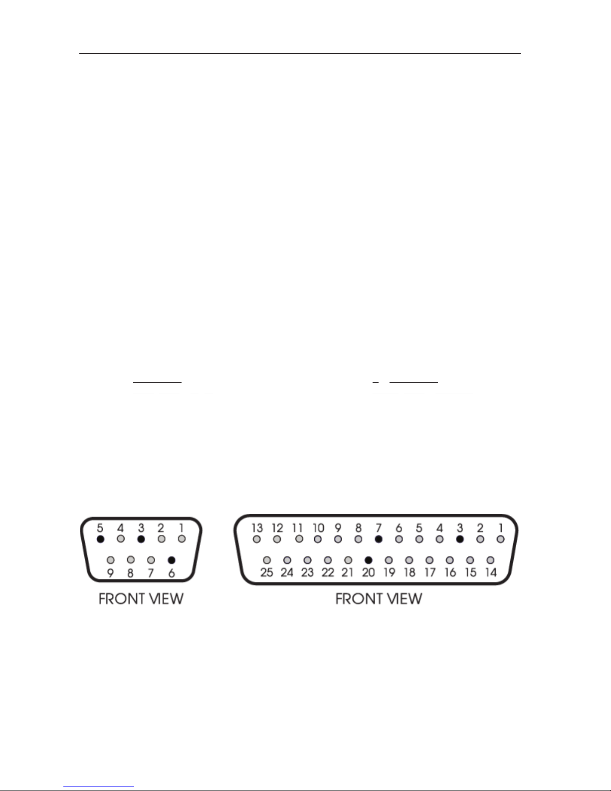
Connecting an external printer
Connect the external printer to the 9 way ‘D’ type plug on the mains input panel at the rear of the test
set.
Lead connections are as shown in figure 25.
Oil test set Typical Printer
9-way ‘D’ type plug 25-way ‘D’ type socket
pin 3 data from oil test set to pin 3
pin 5 signal ground to pin 7
pin 6 printer busy line to pin 20
pins 1, 7, 8 not connected
pins 2, 4, 9 reserved
27
Figure 25. Typical 9 & 25 Way ‘D’ type plug and socket connections to external printer.
Page 28

Downloading Results to a PC
T
o transfer test results to a PC, connect a suitable cable (see below) between the RS232 socket on the
OTS and a serial port on the PC. A suitable communications program is required on the PC.
When the OTS is set to print to an external printer, text will appear on the PC display, which may be
copied to other programs for storage or calculation.
RS232 Cable
T
he following shows the cable connections which has been found to work with Microsoft
®
T
erminal and
Hyperterminal programs:-
PC: ‘D’ type socket OTSAF/2 9 pin ‘D’ type socket
Function 25 Pin 9 Pin Pin Function
RXD (i/p) 3 2 3 TXD (o/p)
GND 7 5 5 GND
RTS (o/p) 4 7 6 Busy (i/p)
DCD (i/p) 8 1
DTR (o/p) 20 4 Joined together
DSR (i/p) 6 6
1, 7, 8 Not connected.
2, 4, 9 Reserved - Do not connect.
Shell Braid Shell
(Screen)
Configuring the OTS
From the main menu, choose OPTIONS and then PRINTER CONTROL. Verify the following settings:-
Baud Rate - 9600
Ext. Printer - ON
It may be useful to set AUTOPRINT to
On, which will cause the OTS to output data automatically after
each test sequence.
Refer to page13 ‘
Setting the Printer options‘
for further information on how to do this.
Configuring the PC Communication Program
The following settings have been found to work with Microsoft®Terminal and Hyperterminal programs.
Baud Rate - 9600
Data Bits - 8
Parity
- None
Stop Bits - 1
Flow Control
-
Hardware
28
Operation
Page 29
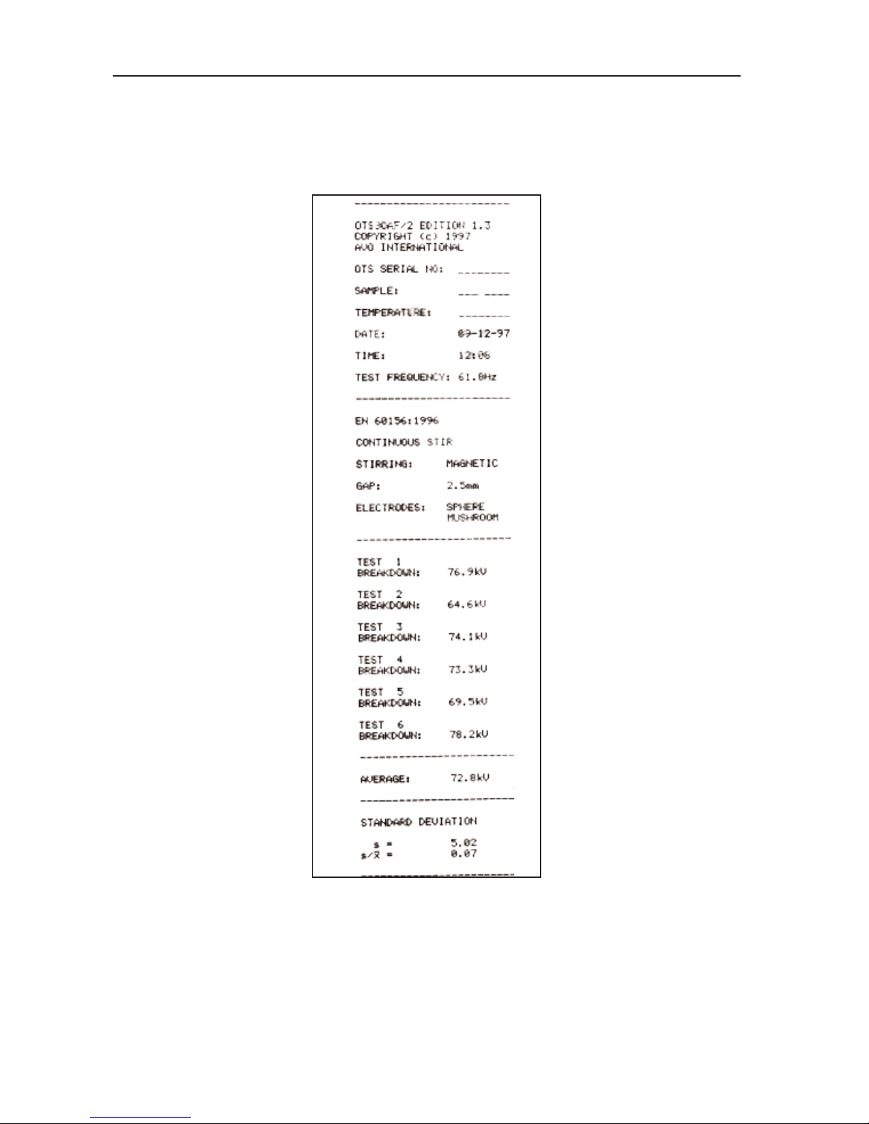
Print Out Information
Each print out provides all information related to the specific test carried out. Headings are also provided
for insertion of sample identification and ambient temperature. Where a standard oil test specification
allows different electrode shape and/or gap, these will be shown on the printout so that the user can
indicate which were used.
Fuse Replacement
Three fuses are fitted in holders mounted on the mains input panel at the rear of the instrument. Ensure
that the test set is disconnected from the supply before fuses are replaced. To replace a fuse unscrew
and remove the cap in the centre of the holder. Remove the fuse, replace with a new one of the correct
size and rating, and refit the cap.
It is important that fuses of the correct rating and type are fitted, (see Specification for details). FS1 is the
mains power supply fuse, 2A rating for a 220 V/240 V supply and 4 A rating for a 110V/120V supply.
FS2 and FS3 are internal power supply fuses of 6,3 A rating.
29
Figure 26.
T
ypical test sequence print-out.
Page 30

The following notes are mainly intended for the guidance of those whose experience in the subject may
be limited. The notes should be read in conjunction with the relevant oil testing specifications.
Causes of Bad Oil
Transformers and switchgear oil may be rendered unsuitable for further use due to four main reasons:-
1. Low dielectric strength.
2
. High acidity.
3. High sludge content.
4. Excessive free water content.
Low dielectric strength may result from many causes, the most common of which is foreign particles or
fibres and water in combination. Individually their effect may be relatively small, but together a
contamination of only a few parts in a million can cause considerable lowering of the breakdown voltage
of the oil. High acidity, sludge and free water should not be tolerated, but will not necessarily reduce the
dielectric strength below acceptable or specified levels.
Appearance of the Sample
Only an experienced person can judge the condition of an insulating oil from its appearance, but a
general guide may be obtained from the following observations:-
1. A cloudy appearance may indicate that sludge has been formed.
2. A dark yellow colour could be a sign of overheating.
3. A blackish colour often results from an arc having taken place with either carbonisation of
the oil or of the insulation within the equipment.
4. A green colour may be due to copper salts dissolving in the oil.
Cleanliness of the Apparatus
The necessity for scrupulous cleanliness in the apparatus and during the process of sampling, cannot be
over emphasised. The measurement of the dielectric strength of the sample is as dependent on the
cleanliness of the test cell and the sampling apparatus as the condition of the oil itself.
After cleaning the apparatus, it should under no circumstances be wiped, dried or even handled with a
dusty or fibrous cloth as loose dust or fibres are liable to cause contamination.
Precautions Necessary During Sampling
Since the oil taken from a drain cock will inevitably contain an excess of settled out solid impurities, and
will not necessarily be representative of the bulk of the oil, it should be run to waste until clear.
Always run off a quantity of oil into a glass bottle or a test tube for an initial check on the appearance of
the oil. Attention to this point may prevent contamination of a clean test vessel.
If necessary, thoroughly clean and dry the sample point using a suitable solvent. Any cloth used should
be lint free. Open the sample cock and drain to waste enough oil to ensure that the sample cock is fully
flushed and the sample is representative of the bulk of oil to be tested. This quantity will depend upon
the size of the transformer or main container. About 2 litres is usually suitable.
When sampling from a drum or supply container, the oil should flow at a steady rate into the test vessel
and after being swilled around the sides it should be discarded. Without altering the rate of flow of the oil
the quantity required for the test should then be run of
f while taking extreme care to prevent the ingress
of atmospheric dust, cloth fibres or moisture. Do not use a syphon. In the absence of a useable sample
point, use a ‘thief’.
Shield the sample from direct light until ready to be tested.
T
urbulence and air bubbles should be avoided when pouring the oil. Relevant national specifications
should be observed.
Particular care to prevent contamination is necessary when a test is to be made on a bulk delivery
tanker, and on all occasions when a high value of dielectric strength is anticipated. The procedure
suggested above should be rigorously applied.
30
Sampling and Testing Oil for Dielectric Strength
Page 31

31
CONSIGNES DE SECURITE
• L
e boîtier d’essai d’huile doit êtrecorrectement mis à la masse.
• L
a chambre d’essai doit êtreconservée scrupuleusement propre.
• Le boîtier d’essai ne doit pas être utilisé si le couvercle de la chambre
d
’essai est fissuré ou endommagé d’une manière quelconque, auquel cas il
doit être renvoyé à un agent autorisé pour réparation.
• Un essai de continuité entre l’emc et la barrière de décharge doit être
effectué régulièrement une fois par semaine.
• Le type correct de récipient d’essai d’huile doit être utilisé, et positionné
correctement sur les guignols de support avant d’effectuer un essai
quelconque.
• Les fusibles de remplacement doivent être du type et de la puissance
corrects.
• Les avertissements et précautions concernant la sécurité doivent être lus et
compris avant de commencer à utiliser l’instrument. Ils doivent être observés
pendant l’emploi.
R
EMARQUE
CONFIEZ L’UTILISATION DE CET BOÎTIER D’ESSAI D’HUILE A UN PERSONNEL QUALIFIE ET COMPETENT
Symboles utilisés sur l'instrument
Consulter le Guide de l'utilisateur
Risque de choc électrique
Équipement conforme aux Directives en vigueur de l'UE
Borne de masse
Page 32

Avertissements
1. Vérifiez que votre appareil d’essai d’huile OTS est correctement mis à la masse avant de
vous en servir. Vous DEVEZ brancher cet appareil sur une prise comportant un conducteur
protecteur de masse. Pour obtenir une mise à la terre efficace, nous vous recommandons de
brancher séparément sur une masse de qualité la borne verte/jaune du panneau d’entrée secteur
qui se trouve au dos de cet appareil d’essai.
2. Avant de brancher l’alimentation secteur, vérifiez que le sélecteur de tension d’alimentation secteur
est réglé sur une valeur qui correspond à l’alimentation électrique que vous comptez employer. Ce
sélecteur se trouve sur le panneau d’entrée secteur, au dos de cet appareil d’essai.
3. Vérifiez que la chambre d’essai est toujours d’une propreté absolue, en particulier avant de procéder
à un essai. Essuyez tout épanchement d’huile dans la chambre d’essai ou dans la cuve d’essai, le
cas échéant. Cette cuve doit occuper l’emplacement prévu dans la chambre d’essai, au-dessus des
cornes supports.
4. Si le couvercle de la chambre d’essai est fissuré ou endommagé, quelle qu’en soit la gravité,
NE
VOUS SERVEZ PAS
de cet appareil d’essai. Faites remplacer ce couvercle par un réparateur agréé
avant de remettre en service cet appareil.
5. Cet appareil d’essai d’huile comporte une barrière métallique d’accouplement électromagnétique et de
décharge à l’intérieur du couvercle de la chambre d’essai. Cette barrière est reliée par deux ressorts à
la broche de masse de la prise d’entrée secteur. Vérifiez régulièrement, toutes les semaines, la
continuité entre cette barrière et cette broche. Il y a également deux contacts de pression entre cette
barrière et le boîtier. Vérifiez l’intégrité de ces contacts lors de la fermeture du couvercle.
6. Cet appareil d’essai est équipé de fusibles en céramique à forte capacité de rupture conformes à la
norme CEI 127. Les fusibles de rechange montés sur cet appareil d’essai doivent respecter cette
norme. Pour obtenir des détails complets, consultez la section Spécifications.
N’EMPLOYEZ PAS de fusibles en verre étant donné que leur capacité de rupture est faible.
7. Sur les appareils d’essai OTS60AF/2, OTS8OAF/2 et OTS100AF/2 utilisez uniquement les cuves
d’essai fabriquées et fournies par Megger Limited et montez-les dans leur chambre respective
d’essai.
Le Figure 27 illustre le type correct de cuve. N’utilisez pas d’autres cuves ou récipients (même s’ils
semblent identiques).
8. L’emploi de cuves incorrectes d’essai d’huile risque d’endommager votre appareil d’essai et peut
entraîner la perte de la garantie.
9. Ne retirez pas les panneaux du boîtier ou les couvercles avant d’avoir débranché votre appareil
d’essai de l’alimentation secteur
. Le non respect de cette consigne, peut vous exposer à des
composants sous tension du circuit. Des condensateurs internes peuvent conserver leur charge,
même après avoir débranché cet appareil d’essai de l’alimentation secteur (en particulier Si une
anomalie est présente). Confiez les réglages et réparations à un personnel qualifié et formé. Si vous
confiez ces activités à un personnel qui n’est pas employé par le fabricant ou l’un de ses agents
agréés, vous risquez de perdre la garantie.
10. Si vous pensez que la protection de votre appareil d’essai a été affectée, NE vous servez PAS de cet
appareil, retirez-le du service et renvoyez-le au fabricant ou à son agent agréé en vue de le faire réparer.
Cette protection risque d’être affectée, par exemple, lorsque cet appareil d’essai présente des signes
visibles d’endommagement, n’effectue pas les mesures prévues, a été stocké pendant longtemps dans
des conditions défavorables ou a été soumis à des contraintes importantes lors d’un transport.
11. Si cet appareil d’essai d’huile a été soumis à des changements importants sur le plan de
l’environnement, c’est-à-dire à des variations extrêmes d’humidité ou de température, vous devez
attendre qu’il s’adapte aux nouvelles conditions en vigueur pendant au moins 12 heures avant de
vous en servir.
32
Fonctionnement
Page 33

Préparation de la cuve d’essai
1. Séparez la cuve et le couvercle qui porte les supports des électrodes.
2. Vérifiez que la cuve est d’une propreté absolue, à l’intérieur et à l’extérieur.
3
. Fixez les électrodes appropriées sur les bras coulissants si elles ne sont pas en place. Il vous faudra
probablement desserrer une ou plusieurs vis de serrage au pied de ces supports pour repousser
ces bras. Ces bras ont un ergot fileté sur lequel viennent se visser des électrodes. Vissez les
électrodes et serrez-les aux doigts.
4. Réglez l’écartement des électrodes sur la valeur spécifiée, en fonction de l’essai à réaliser. La
trousse d’accessoires contient, dans ce but, des calibres d’écartement. Desserrez les vis de serrage
au pied des deux supports d’électrodes et écartez les bras coulissants pour centrer l’écartement
entre ces deux supports. Resserrez la vis de serrage d’un support pour immobiliser un côté puis
ajustez l’autre extrémité de telle sorte que lorsque vous introduisez le calibre entre les électrodes, ce
calibre touche simultanément les deux électrodes. Resserrez la vis de serrage du deuxième support.
Une fois ce réglage terminé, revérifiez l’écartement.
Le
T
ableau suivant présente des profils d’électrodes et des écartements pour des essais standard.
Chaque écran d’affichage d’essai présente également le profil des électrodes, leur écartement et le
type d’agitation pour chaque spécification d’essai préprogrammée, en fonction des besoins.
5. Nettoyez la cuve en respectant les consignes spécifiées pour l’essai à réaliser puis remplissez en
partie le récipient de cette cuve d’un échantillon d’huile jusqu’à ce que le niveau vienne se situer à
environ 12 mm de la partie supérieure.
6. Le cas échéant, plongez une barre magnétique d’agitation propre (sauf pour les spécifications ASTM
D877 et ASTM D1816, ou chaque fois que l’agitation par roue à aubes a été sélectionnée).
Remarque: la norme
ASTM D1816 demande une agitation continue qui est assurée par la cuve spéciale
D1816 équipée d’une roue à aubes entraînée par le moteur
. Consultez la Figure 34 de la page
39.
7.
Remontez avec précaution les deux éléments de cette cuve d’essai.
33
Figure 27. Cuve d’essai d’huile des appareils
Support
d’electrode
Bras gainé de
connexion
Récipient
Electrodes
Brass
coulissant
Vis de serrage
Couvercle
Page 34

Chargement de la cuve d’essai
1. Ouvrez le couvercle de la chambre d’essai en tournant d’un quart de tour dans le sens inverse des
aiguilles d’une montre le bouton de verrouillage à clé imperdable et en le tirant vers l’extérieur.
2. Placez la cuve d’essai dans la chambre: les extrémités des bras de connexion doivent reposer sur
les bornes du bâti, en haut des cornes supports. Essuyez tout épanchement d’huile.
Remarque: Sur une cuve ASTM D1816, branchez le conducteur du moteur électrique de l’agitateur à
palettes sur la prise d’alimentation qui se trouve à la partie supérieure arrière de la chambre
d’essai.
Attention: procédez à un examen visuel pour confirmer que les deux contacts de mise à la masse à
ressort qui relient l’accouplement électromagnétique et la barrière métallique de
décharge du couvercle de la chambre au dos de cette dernière, sont intacts (voir Figure
28).
3. Refermez le couvercle de la chambre d’essai. Pour cela, enfoncez-le puis tournez le bouton de
verrouillage dans le sens des aiguilles d’une montre pour immobiliser ce couvercle.
Préparation de l’appareil d’essai d’huile
1. Le cas échéant, réglez le sélecteur de tension secteur puis branchez l’appareil d’essai d’huile sur
une alimentation correcte. Nous vous recommandons de brancher la borne verte/jaune de mise à la
34
Fonctionnement
Spécifications
sélectionées
d’essai
normalise
Profit des
électrodes
Ecartement
des électrodes
ASTM D1816
ASTM D877
2,5 mm
1 or 2 mm
2,54 mm
EN60156
AS 1767 BS148
BS 5874 CEI 10-1
IEC 156 IP 295
NFC 27 ΓOCT 6581
SABS 555 VDE 0370
UNE 21 STAS 286
OU
Figure 28. Contact de mise à la masse à ressort sur le couvercle de la chambre d’essai.
Page 35

terre sur une masse jaune de qualité.
2. Mettez sous tension l’alimentation secteur et l’appareil d’essai. Le message de droits d’auteur
(copyright) apparaît brièvement à l’écran puis est remplacé par l’écran du menu principal de
programmation. Ce menu offre les options suivantes:
AS 1767-1976
A
STM D877
ASTM D1816-84a
BS148:1984
BS5730a: 1979
BS5874: 1980
CEI 10-1 1987
CEI 156 1995
EN60156 (1996)
OPTIONS
IP 295/83
NFC 27-221:1974
GOCT 6581-75
SABS 555-1985
STAS 286-81
UNE 21-309-89
VDE 0307/84
ESSAI 5 MINUTES
AUTOVERIFICATION
VERIF. ETALONNAGE
ESSAI OPERATEUR
ESSAI TENUE
L’écran du menu principal attribue des étiquettes aux trois touches de commande, en fonction des
fonctions qu’elles assurent. Ces fonctions changent.
Lors de la mise sous tension, ces touches sont, de la gauche vers la droite,
s, t et CHOIX. La
touche gauche et la touche centrale contrôlent le défilement vers le haut et vers le bas des
différentes options de ce menu alors que la touche CHOIX confirme l’option mise en valeur.
Remarque: l’écran ne montre à un moment donné que cinq options du menu et les options ainsi
visualisées dépendent de la dernière option employée. Lorsque vous faites défiler ces options,
l’option mise en valeur est celle que vous pouvez sélectionner.
3. Sélectionnez l’option requise puis respectez les consignes qui apparaissent à l’écran.
Sélection d’OPTIONS du menu principal
Le sous-menu OPTIONS vous permet de programmer et de mémoriser vos préférences personnelles en ce
qui concerne les paramètres suivants:
CONTRASTE AFFICHAGE
CONTRE-ECLAIRAGE AFFICHAGE
LANGUE
COMMANDE IMPRIMANTE
HEURE/DA
TE
Remarque: tous ces réglages restent dans la mémoire interne lorsque vous mettez votre appareil hors
circuit ou lorsque vous ouvrez le contacteur de verrouillage du couvercle de la chambre d’essai.
Faites défiler les dif
férentes possibilités et sélectionnez celle qui vous intéresse, comme indiqué
précédemment. Mettez en valeur le mot MENU puis appuyez sur CHOIX pour revenir au menu principal.
Contraste de l’affichage
Lorsque vous sélectionnez le paramètre CONTRASTE
AFFICHAGE, vous pouvez vous servir de la touche
centrale et de la touche gauche pour ajuster la qualité de lecture de l’écran d’affichage. Appuyez sur CHOIX
pour revenir au sous-menu OPTIONS.
Remarque: pour faire apparaître rapidement le contraste de l’affichage à l’écran, il vous suffit dappuyer sur
la touche centrale lorsque vous mettez votre appareil d’essai sous tension. Maintenez la
pression sur cette touche pendant environ 1 seconde après cette mise en marche.
Contre-éclairage de l’affichage
Lorsque vous sélectionnez le paramètre CONTRE-ECLAIRAGE
AFFICHAGE, vous pouvez vous servir de la
35
Page 36

touche centrale et de la touche gauche pour mettre en circuit ou hors circuit, en fonction de vos besoins, le
contre-éclairage de l’affichage. Appuyez sur CHOIX pour revenir au sous-menu OPTIONS.
Sélection de la langue
Vous pouvez programmer l’écran d’affichage et les impressions sur l’une des six langues suivantes:
ENGLlSH
F
RANCAIS
DEUTSCH
ESPANOL
PORTUGUES
ITALIANO
Faites défiler les différentes possibilités et sélectionnez celle qui vous intéresse, comme indiqué
précédemment. Appuyez sur CHOIX pour revenir au sous-menu.
Remarque: pour faire apparaître rapidement l’écran de sélection de langue, appuyez sur la touche droite
lorsque vous mettez votre appareil d’essai sous tension. Lorsque vous avez terminé cette
sélection, passez au reste du sous-menu OPTIONS.
Réglage des options de l’imprimante
Faites défiler le sous-menu OPTIONS jusqu’à la ligne COMMANDE IMPRIMANTE puis appuyez sur CHOIX.
Un nouveau sous-menu apparaît à l’écran:
DERNIERS RESULTATS
AUTO-IMPRES
No EXEMPLAIRES
TAUX BAUDS
FIN
IMP. INT. MARCHE
IMP. EXT. ARRET
Suivant les cas, l’état de chaque option vient s’inscrire (exemple : No EXEMPLAIRE 1). Vous pouvez le
modifier en fonction de vos besoins en appuyant à plusieurs reprises sur la touche CHOIX. Par exemple,
pour changer le mode MARCHE/ARRET de l’imprimante interne, faites défiler ce sous-menu jusqu’à la ligne
IMP. INT. puis appuyez sur CHOIX. Dans ce cas-là, l’imprimante interne est normalement en marche.
Remarque: plusieurs pressions successives sur la touche CHOIX permettent d’alterner entre le mode
MARCHE et le mode ARRET pour l’imprimante interne. Dans ce cas-là, le paramètre IMP. EXT.
(c’est-à-dire l’option IMPRIMANTE EXTERNE) passe automatiquement dans le mode opposé.
Par conséquent, vous ne pouvez pas utiliser simultanément l’imprimante interne et une
imprimante externe.
Si vous comptez vous servir d’une imprimante externe, vous devez ajuster le taux en bauds de l’appareil
d’essai sur celui de cette imprimante. Pour cela, faites défiler le menu pour mettre en valeur la ligne TAUX
BAUDS. Plusieurs pressions successives sur la touche CHOIX permettent de faire défiler les différentes taux
standard en bauds qui sont proposés: 9 600, 4 800, 2 400, 1 200, 600, 300 et 150. Laissez à l’écran celui
que vous choisissez. Lé format de transfert des données est lé suivant:
1 bit de départ
8 bits de données
1 bit d’arrêt
pas de parité
Vous pouvez imprimer un ou deux exemplaires dés résultats. Faites défiler lé menu jusqu’à la ligné No
EXEMPLAIRES puis appuyez sur CHOIX pour choisir 1 ou 2. Laissez à l’écran le numéro dé votre choix. Si
vous avez choisi l’option DERNIERS RESUL
T
A
TS, pour imprimer la dernière série dé résultats d’essais vous
devez appuyer sur la touché CHOIX.
Remarque: la dernière sérié de résultats d’essais reste dans la mémoire interné lorsque vous mettez cet
instrument hors circuit ou lorsque vous ouvrez lé contacteur dé verrouillage du couvercle dé la
chambré d’essai. Lapparéil d’essai imprimé automatiquement lés résultats d’un essai terminé, à
condition que vous ayez programmé lé paramètre AUTO-IMPRES sur MARCHE. Faites défiler
le menu, comme indiqué précédemment, pour mettre én valeur cette option puis, lé cas
échéant, appuyez sur CHOIX pour faire apparaître l’état souhaité. Si vous choisissez l’état
ARRET
, pour ce paramètre, l’option IMPRES. vous est proposée à la fin dé chaque séquence
d’essais.
Pour revenir au sous-menu OPTIONS, faites défiler les paramètres pour mettre en valeur la ligne FIN puis
36
Fonctionnement
Page 37

appuyez sur CHOIX. Pour revenir au menu principal, à partir du sous-menu OPTIONS, faites défiler la liste
pour mettre en valeur l’option MENU puis appuyez sur CHOIX.
HEURE/DATE
L’heure et la date correctes sont programmées en usine et, normalement, vous n’avez pas besoin d’effectuer
d’ajustement. L’horloge interne de 24 heures est alimentée par une pile au LITHlUM qui a une durée de vie
d
e 10 ans.
Lorsque vous sélectionnez l’option HEURE/DATE, un nouveau sous-menu apparaît, comme indiqué ciaprès:
FORMAT DATE
VUE
FIN
REG DATE
REG HEURE
Faites défiler les différentes possibilités et sélectionnez celle qui vous intéresse, comme indiqué précédemment.
L’option FORMAT DATE vous offre le choix entre une date de type européen (jj-mm-aa) ou une date de type
américain (mm/jj/aa). Plusieurs pressions sur la touche CHOIX vous permettent de choisir le type de votre
choix.
Pour ajuster la date. faites défiler les options jusqu’à la ligne REG DATE puis appuyez sur CHOIX. Pour
régler la date, utilisez la touche gauche et la touche centrale puis appuyez sur CHOIX. Ensuite, procédez de
même pour régler le mois puis le jour.
Pour ajuster l’heure. faites défiler les options jusqu’à la ligne REG HEURE, puis appuyez sur CHOIX. Utilisez
la touche gauche et la touche centrale pour régler les heures puis appuyez sur CHOIX. Procédez de même
pour régler les minutes.
L’option VUE vous permet d’afficher la date et l’heure sous le format sélectionné. Pour revenir au sousmenu, faites défiler les paramètres jusqu’à la ligne FIN puis appuyez sur CHOIX.
Pour revenir au menu principal, faites défiler les paramètres jusqu’à l’option MENU puis appuyez sur CHOIX.
Séquences d’essais automatiques
Choisissez le programme souhaité préprogrammé de spécifications d’essais huile sur le menu principal an
faisant défiler ce dernier à l’aide des touches s et t, afin de mettre en valeur la spécification de votre choix.
Appuyez ensuite sur CHOIX.
Lorsque vous avez ainsi sélectionné une spécification d’essai, l’écran indique le nom de cet essai (qui reste
visible pendant toute cette séquence d’essais) et vous of
fre la possibilité de démarrer cette séquence à l’aide
de la touche gauche DEPART. La touche droite MENU vous permet de revenir au menu principal. Pour
chaque spécification d’essai distincte, l’écran indique les choix appropriés de profil et d’écartement des
électrodes, Si la spécification retenue stipule ces paramètres. La méthode d’agitation est également
indiquée. Si l’option MODE AGIT apparaît à l’écran, vous pouvez modifier le type d’agitation et choisir
AIMANT (barre magnétique d’agitation). ROUE (cuve d’essai à agitateur) ou NEANT, en fonction de l’essai
sélectionné.
Chaque fois que vous lancez une séquence d essais, cette dernière se déroule automatiquement.
Remarque: le logiciel à microprocesseurs contient des sous-programmes qui contrôlent le fonctionnement
de cet appareil d’essai d’huile. Si un probléme apparaît, ce qui est fort peu probable, qu’il soit
provoqué par cet appareil ou par un événement extérieur
, lorsque vous reprenez l’essai en
cours. ce dernier se déroule à partir du point où s’est produit ce problème. Si cela s’avère
impossible. l’appareil d’essai est placé à l’état de sécurité et un message indiquant la situation
présente apparaît à l’écran.
37
Page 38

ESSAI DE 5 MINUTES
Remarque: cet essai n’est pas standard et a pour but de vérifier rapidement les caractéristiques de l’huile.
1. Pour commencer cet essai, mettez en valeur l’option ESSAI 5 MINUTES sur le menu principal puis
appuyez sur CHOIX. L’écran de la Figure 29 apparaît alors.
Plusieurs pressions sur la touche centrale MODE AGIT vous permettent d’alterner entre le mode
d’agitation AIMANT, le mode ROUE et NEANT. Appuyez sur la touche droite MENU pour revenir au
menu principal.
2. Lorsque vous appuyez sur la touche DE PART, l’écran de la Figure 30 apparaît.
Cet écran indique que le temps de repos initial d’une minute a été enclenché et le temps restant
vient s’inscrire en secondes.
3.
Dès que le temps de repos initial s’est écoulé, la tension d’essai élevée est automatiquement mise
en circuit et est envoyée à l’échantillon. Un écran identique à la Figure 31 affiche ESSAI 1.
Le témoin haute tension s’allume et l’écran indique l’application sur l’échantillon d’huile d’une tension
qui s’élève au rythme de 2 kV/s. Cette élévation de tension se poursuit jusqu’à ce qu’un
fractionnement se produise (ou jusqu’à ce qu’une valeur maximale soit atteinte). Le numéro de
l’essai en cours vient s’inscrire et s’accompagne des mots EN MARCHE.
38
Fonctionnement
Figure 29. Ecran initial d’affichage de sélection du mode Agitation.
Figure 30. Ecran d’affichage du temps de repos initial.
Figure 31. Ecran d’affichage de la fonction appliquée.
ESSAI 5 MINUTE
MODE AGIT
FIN
DEPART
AGITATION: AIMANT
2.5
mm
TEMPS RESTANT
01:00
TEMPS REPOS INITIAL
ARRET
ESSAI 5 MINUTE
XX kV
ESSAI 1
EN MARCHE
ARRET
ESSAI 5 MINUTE
Page 39

4. Lorsqu’un fractionnement se produit (ou lorsque la tension maximale est atteinte), la tension d’essai
est coupée, le témoin haute tension s’éteint et l’appareil d’essai commence sa phase d’agitation de
l’échantillon d’huile. L’agitateur tourne pendant 30 secondes et la tension de fractionnement de
l’essai principal reste à l’écran. L’écran illustré à la Figure 32 apparaît alors.
Le temps d’agitation restant apparaît en alternance avec le mot AGITATION.
5. Lorsque l’agitation est terminée, l’écran indique le lancement d’une période intermédiaire de repos
de 30 secondes et le temps restant vient s’inscrire, en alternance avec le mot REPOS. La tension
de fractionnement reste à l’écran qui est identique à celui de la Figure 33.
6. Lorsque l’opération décrite à l’alinéa 5 est terminée, la tension d’essai remonte, comme indiqué à
l’alinéa 3, mais cette fois-ci pour l’ESSAI 2 et le cycle décrit précédemment se répète.
7. Les opérations des alinéas 3, 4, 5 et 6 se répètent lors de la troisième application de la tension
d’essai. Dès que cette troisième tension d’essai est coupée, l’écran indique la tension moyenne de
fractionnement de ces trois essais séquentiels. L’écran de la Figure 34 apparaît alors.
Les trois touches de commande permettent d’effectuer des fonctions différentes. Une pression sur la
touche gauche VUE fait apparaître, dans un ordre séquentiel, la tension de fractionnement de
chaque essai, puis l’écart standard. Si vous avez sélectionné au préalable l’option d’impression
automatique, les résultats sont automatiquement imprimés à la fin de chaque séquence d’essais. Si
ce n’est pas le cas, appuyez sur la touche centrale IMPRES> pour obtenir l’impression des résultats.
Lorsque l’imprimante est en marche, l’indication IMPRES
A
TTENDEZ SVP
apparaît à l’écran.
Appuyez sur la touche NOUVEAU pour revenir au début de l’ESSAI 5 MINUTES. Appuyez ensuite
sur la touche gauche DEP
AR
T
pour recommencer une séquence d’essais ou sur la touche MENU
39
Figure 32. Ecran d’af
fichage du mode agitation.
XX kV
ESSAI 1
00:30
ARRET
ESSAI 5 MINUTES
Figure 33. Ecran d’affichage du temps de repos intermédiaire.
XX kV
ESSAI 1
REPOS
ARRET
ESSAI 5 MINUTES
Figure 34. Ecran d’affichage de la tension moyenne de fractionnement
XX kV
REPOS
ARRETVUE IMPRES.
ESSAI 5 MINUTES
Page 40

pour revenir au menu principal.
Remarque: à tout moment, pendant le déroulement d’une séquence d’essais, vous pouvez appuyer sur la
touche de commande droite ARRET pour mettre fin à un essai et revenir à l’écran d’affichage
des options d’essais. De même, pendant une impression, vous pouvez appuyez sur la touche
gauche ARRET pour mettre fin à cette fonction d’impression et revenir a l’écran d’affichage de
l
a tension moyenne de fractionnement.
Essais AS 1767, BS148, BS5874, CEl 10-1, IEC 156, lP 295, NFC 27, ΓOCT 6581, SABS 555, STAS 286,
UNE 21 et VDE 0370.
Remarque: ces spécifications offrent la possibilité de vous servir d’électrodes sphériques ou bombées.
1. Pour commencer, mettez en valeur l’essai sélectionné sur le menu principal puis appuyez sur
CHOIX. L’affichage illustré à la Figure 29 apparaît. Appuyez sur la touche droite MENU pour revenir
au menu principal. Plusieurs pressions sur la touche centrale MODE AGIT vous permettent
d’alterner entre le mode d’agitation AIMANT, le mode ROUE et NEANT.
2. Lorsque vous appuyez sur la touche DEPART, l’ESSAI 1 se déclenche. L’affichage illustré à la
Figure 31 apparaît. Il indique que le temps de repos initial a été enclenché et le temps restant vient
s’inscrire en minutes et secondes.
3. Dès que le temps de repos initial s’est écoulé, la tension d’essai élevée est automatiquement mise
en circuit et est envoyée à l’échantillon d’huile. Un écran identique à la Figure 31 apparaît.
Cet écran indique que la tension s’élève au rythme de 2 kV/s. Cette élévation de tension se poursuit
jusqu’à ce qu’un fractionnement se produise (ou jusqu’à ce qu’une valeur maximale soit atteinte). L’e
numéro de l’essai en cours vient s’inscrire et s’accompagne des mots EN MARCHE.
4. Lorsqu’un fractionnement se produit (ou lorsque la tension maximale est atteinte), la tension d’essai
est coupée, le témoin haute tension s’éteint et l’appareil d’essai commence sa phase d’agitation
intermédiaire. L’agitateur tourne pendant une minute et la tension de fractionnement précédente
reste à l’écran. L’écran illustré à la Figure 32 apparaît alors.
Le temps d’agitation restant apparaît en alternance avec le mot AGITATION.
5. Lorsque l’agitation est terminée, l’écran indique le lancement d’une période intermédiaire de repos.
Le temps restant vient s’inscrire, en alternance avec le mot REPOS. La tension de fractionnement
précédente reste à l’écran qui est identique à celui de la Figure 33.
6. La tension d’essai commence de nouveau à s’élever, comme à l’alinéa 2, mais cette fois-ci pour
l’ESSAI 2 et le cycle décrit précédemment se répète.
7. Pour ces spécifications, il y a 6 essais consécutifs. Dès que la tension du dernier essai est coupée,
l’écran indique la tension moyenne de fractionnement de ces 6 essais séquentiels. L’écran de la
Figure 33 apparaît alors.
Remarque: (1) Les spécifications d’essais NFC27, ST
AS 286 et UNE2l dif
fèrent des descriptions
précédentes car elles utilisent les 5 derniers résultats des 6 essais pour calculer l’écart moyen
et standard. (2) Le programme de l’essai BS148 fixe une limite autorisée de 30 kV, comme
l’exigent les spécifications de cette norme.
Les trois touches de commande assurent maintenant d’autres fonctions. Une pression sur la touche gauche
VUE fait apparaître, dans un ordre séquentiel, la tension de fractionnement de chaque essai, puis l’écart
standard. Si vous avez sélectionné au préalable l’option d’impression automatique, les résultats sont
automatiquement imprimés à la fin de chaque séquence d’essais. Si ce n’est pas le cas, appuyez sur la
touche centrale IMPRES, pour obtenir l’impression des résultats. Lorsque l’imprimante est en marche,
l’indication IMPRES ATTENDEZ SVP apparaît à l’écran. Appuyez sur la touche NOUVEAU pour revenir au
début de l’essai sélectionné. Appuyez ensuite sur la touche gauche DEPART pour recommencer une
séquence d’essais ou sur la touche MENU pour revenir au menu principal.
Remarque: à tout moment, pendant le déroulement d’une séquence d’essais, vous pouvez appuyer sur la
touche de commande droite
ARRET
pour mettre fin à un essai et revenir à l’écran d’af
fichage
des options d’essais. De même, pendant une impression, vous pouvez appuyer sur la touche
gauche ARRET pour mettre fin à cette fonction d’impression et revenir à l’écran d’affichage de
la tension moyenne de fractionnement.
40
Fonctionnement
Page 41

Essai ASTM D877
Remarque: cette spécification n’a pas besoin d’agitation. Par conséquent, ne montez pas une barre
magnétique d’agitation.
1. Pour commencer cet essai, mettez en valeur l’option ASTM D877 sur le menu principal puis
a
ppuyez sur CHOIX.
2. Une pression sur la touche DEPART enclenche l’ESSAI i et l’écran de la Figure 30 apparaît. Cet écran
indique que le temps de repos initial de 2 minutes 20 secondes a été enclenché et le temps restant
vient s’inscrire. Dés que le temps de repos initial s’est écoulé, la tension d’essai élevée est
automatiquement mise en circuit et envoyée à l’échantillon. Un écran identique à la Figure 31
apparaît.
Le témoin haute tension s’allume et l’écran indique que la tension appliquée s’élève au rythme de 3
kV/s. Cette élévation de tension se poursuit jusqu’à ce qu’un fractionnement se produise (ou jusqu’à
ce qu’une valeur maximale soit atteinte). Le numéro de l’essai en cours vient s’inscrire et
s’accompagne des mots EN MARCHE.
3. Lorsqu’un fractionnement se produit (ou lorsque la tension maximale est atteinte), la tension d’essai
est coupée, le témoin haute tension s’éteint et l’écran indique que la période intermédiaire de repos
d’une minute est enclenchée. Le temps restant vient s’inscrire, en alternance avec le mot REPOS.
La tension précédente de fractionnement reste à l’écran qui est identique à celui de la Figure 33.
4. Lorsque le temps intermédiaire de repos s’est écoulé, la tension d’essai remonte, comme indiqué à
l’alinéa 2, mais cette fois-ci pour l’ESSAI 2 et le cycle décrit précédemment se répète.
5. Pour cette spécification, il y a 5 essai consécutifs. Dès que la tension du dernier essai est coupée,
l’écran indique la tension moyenne de fractionnement de ces 5 essais séquentiels. Lécran de la
Figure 34 apparaît alors.
Les trois touches de commande permettent d’effectuer des fonctions différentes. Une pression sur la
touche gauche VUE fait apparaître, dans un ordre séquentiel, la tension de fractionnement de
chaque essai, puis l’écart standard.
Si vous avez sélectionné au préalable l’option d’impression automatique, les résultats sont
automatiquement imprimés à la fin de chaque séquence d’essais. Si ce n’est pas le cas, appuyez
sur la touche centrale IMPRES. pour obtenir l’impression des résultats. Lorsque l’imprimante est en
marche, l’indication IMPRES ATTENDEZ SVP apparaît à l’écran.
Appuyez sur la touche NOUVEAU pour revenir au début de l’essai ASTM D877. Appuyez ensuite
sur la touche gauche DE P
AR
T pour recommencer une séquence d’essais ou sur la touche MENU
pour revenir au menu principal.
Remarque: à tout moment, pendant le déroulement d’une séquence d’essais, vous pouvez appuyer sur la
touche de commande droite ARRET pour mettre fin à un essai et revenir à l’écran d’affichage
des options d’essais. De même, pendant une impression, vous pouvez appuyer sur la touche
gauche
ARRET
pour mettre fin à cette fonction d’impression et revenir à l’écran d’af
fichage de
la tension moyenne de fractionnement.
Essai ASTM D1816
Remarque: cet essai a besoin d’une agitation continue à l’aide d’un dispositif à palettes, et en utilisant la
cuve spéciale prévue pour cette spécification. Consultez la Figure 35. V
ous pouvez réaliser cet
essai sur des cuves standard d’essai d’huile mais cette solution n’est pas conforme à ces
spécifications. Le cas échéant, vous pouvez sélectionner l’agitateur magnétique. Lagitateur à
palettes se branche sur la prise qui se trouve au dos de la chambre d’essai, lorsque vous
mettez la cuve d’essai sur les cornes haute tension.
1. Pour commencer cet essai, mettez en valeur l’option ASTM D1816-84a sur le menu principal puis
appuyez sur CHOIX. Lécran de la Figure 29 apparaît alors. Plusieurs pressions sur la touche
centrale MODE
AGIT vous permettent d’alterner entre le mode d’agitation AIMANT, le mode ROUE
et NEANT
.
Appuyez sur la touche droite MENU pour revenir au menu principal.
2. Lorsque vous appuyez sur la touche DEPART, l’ESSAI 1 est enclenché et l’écran de la Figure 30
apparaît. Si vous l’avez sélectionné, l’agitateur se met en route et continue de tourner pendant toute
la séquence d’essais.
41
Page 42

Cet écran affiche le mode d’agitation sélectionné et indique que le temps de repos initial de 3
minutes a été enclenché. Le temps restant initial vient s’inscrire en minutes et secondes.
3. Dès que le temps de repos initial s’est écoulé, la tension d’essai élevée est automatiquement mise
en circuit et est envoyée à l’échantillon d’huile. Un écran identique à la Figure 31 apparaît.
Le témoin haute tension s’allume et l’écran indique l’application d’une tension qui s’élève au rythme
de 0,5 kV/s. Cette élévation de tension se poursuit jusqu’à ce qu’un fractionnement se produise (ou
jusqu’à ce qu’une valeur maximale soit atteinte). Le numéro de l’essai en cours vient s’inscrire et
s’accompagne des mots EN MARCHE.
4. Lorsqu’un fractionnement se produit (ou lorsque la tension maximale est atteinte), la tension d’essai
est coupée, le témoin haute tension s’éteint et l’écran indique l’enclenchement d’une période
d’agitation intermédiaire d’une minute. Ce temps d’agitation vient s’inscrire en secondes, en
alternance avec le mot AGITATION. La tension de fractionnement précédente reste à l’écran qui est
identique à celui de la Figure 32.
5. Dès que le temps intermédiaire d’agitation est terminé, la tension d’essai remonte, comme indiqué à
l’alinéa 3, mais cette fois-ci pour l’ESSAI 2 et le cycle décrit précédemment se répète.
6. Pour cette spécification, il y a 5 essais consécutifs. Dès que la tension du dernier essai est coupée,
l’écran indique la tension moyenne de fractionnement de ces 5 essais séquentiels. L’écran de la
Figure 34 apparaît alors.
Les trois touches de commande permettent d’effectuer des fonctions différentes. Une pression sur la
touche gauche VUE fait apparaître, dans un ordre séquentiel, la tension de fractionnement de
chaque essai puis l’écart standard.
Si vous avez sélectionné au préalable l’option d’impression automatique, les résultats sont
automatiquement imprimés à la fin de chaque séquence d’essais. Si ce n’est pas le cas, appuyez
sur la touche centrale IMPRES. pour obtenir l’impression des résultats. Lorsque l’imprimante est en
marche, l’indication IMPRES ATTENDEZ SVP apparaît à l’écran.
Appuyez sur la touche NOUVEAU pour revenir au début de l’essai
ASTM D1816.
Appuyez ensuite
sur la touche gauche DEPART pour recommencer une séquence d’essais ou sur la touche MENU
pour revenir au menu principal.
Remarque: à tout moment, pendant le déroulement d’une séquence d’essais, vous pouvez appuyer sur la
touche droite
ARRET
pour mettre fin à un essai et revenir à l’écran d’affichage des options
d’essais. De même, pendant une impression, vous pouvez appuyer sur la touche gauche
ARRET pour mettre fin à cette fonction d’impression et revenir à l’écran d’affichage de la
tension moyenne de fractionnement.
Essai de PERSONNALISATION
Cette option vous permet, en tant qu’opérateur, de programmer vos propres paramètres d’essais. Par
conséquent, cet essai de personnalisation est la solution idéale pour programmer d’autres spécifications
d’essai d’huile. V
ous pouvez ainsi programmer un maximum de cinq essais personnalisés. Les essais ainsi
programmés sont conservés en mémoire et vous pouvez vous en servir ultérieurement.
42
Fonctionnement
Figure 35. Cuve d’essai d’huile pour la spécification ASTM D1816
Page 43

Programmation d’un essai de PERSONNALISATION
1. Sur le menu principal, sélectionnez l’option ESSAI OPERATEUR.
Les trois touches de commande assurent les fonctions: SUIVANT, CHOIX et MENU.
Une pression sur la touche SUIVANT vous permet de passer à l’ESSAI DE PERSONNALISATION
suivant (sur les 5 qui sont mis à votre disposition).
Une pression sur la touche MENU vous ramène au menu principal. Une pression sur CHOIX permet de
vous déplacer dans les options de programmation et d’essai de l’essai spécifique de personnalisation
ESSAI OPERATEUR. Ces trois touches assurent maintenant des fonctions différentes: DEPART,
PROG et FIN. Une pression sur la touche FIN vous ramène à l’affichage précédent. Une pression sur
la touche DE PART lance une séquence d’essais basée sur les paramètres affichés. Une pression sur
la touche PROG vous permet de modifier ces paramètres d’essais.
2. Pour modifier les paramètres d’essais, appuyez sur la touche centrale PROG. Les trois touches de
commande assurent alors des fonctions différentes: CHANGER, IMPRES. et FIN. Une pression sur
la touche FIN vous ramène au sous-menu principal. Une pression sur la touche IMPRES. vous
permet d’imprimer les paramètres d’essais affichés à l’écran.
3. Appuyez sur la touche gauche CHANGER pour entrer dans le sous-menu de réglage du TEMPS
REPOS INITIAL. Utilisez la touche gauche pour diminuer les minutes et les secondes affichées à
l’écran et la touche centrale pour augmenter ces minutes et secondes. Lorsque la valeur souhaitée
est à l’écran, appuyez sur CHOIX pour confirmer votre sélection et pour passer au sous-menu du
paramètre suivant à programmer.
Remarque: plusieurs pressions sur une touche modifient la valeur af
fichée par paliers de 5 secondes. Si
vous maintenez la pression sur une touche, la valeur change par paliers de 5 secondes et
passe à la minute suivante puis change par paliers d’une minute (avec un maximum de 99
minutes 55 secondes).
4. Vous pouvez maintenant programmer le nombre d’essais d’une séquence spécifique en utilisant de
nouveau pour concrétiser votre sélection la touche gauche et la touche centrale. Appuyez sur
CHOIX lorsque la valeur souhaitée est à l’écran. Cela confirme votre sélection et vous permet de
passer au sous-émenu du paramètre suivant à programmer
.
Remarque: plusieurs pressions sur une touche en modifient la valeur par paliers unitaires. Si vous
maintenez la pression sur une touche, la valeur change par paliers unitaires, à cinq reprises,
puis change par paliers de cinq (avec une valeur maximale de 99).
5.
V
ous pouvez maintenant programmer la vitesse d’élévation de la tension d’essai. Utilisez pour cela
la touche gauche et la touche centrale pour obtenir la vitesse souhaitée puis appuyez sur CHOIX
lorsque la valeur recherchée apparaît à l’écran.
Remarque: une pression sur une touche modifie de 0,5 kV/s la valeur et il n’y a pas de fonction de
changement rapide (valeur maximale de 5 kV/s).
6. Laffichage offre maintenant les options d’agitation de l’huile. Plusieurs pressions sur la touche
centrale MODE vous permettent d’alterner entre le mode d’agitation
AIMANT, le mode ROUE et
NEANT
. Si vous choisissez l’option NEANT
, il n’y a pas d’agitation intermédiaire.
Appuyez à
plusieurs reprises sur la touche gauche CONT. pour alterner entre la MARCHE et l’ARRET de
l’agitation continue. Si vous choisissez l’option d’agitation continue CONT., il n’y a pas de temps de
repos intermédiaire.
Appuyez sur CHOIX lorsque l’écran af
fiche les options de votre choix.
43
Figure 36. Ecran d’affichage de l’ESSAI OPERATEUR
N. DES ESSAI 1
VITESSE MONTEE 2:0
TEMPS AGITATION 0:30
TEMP REPOS 0:45
ESSAI OPERATEUR 1
SUIVANT
CHOIX
PROG
Page 44

7. Si vous avez sélectionné un temps d’agitation intermédiaire, vous pouvez maintenant programmer à
l’écran une durée comprise entre 0 seconde et 99 minutes 55 secondes. Utilisez la touche gauche
et la touche centrale pour faire apparaître la durée souhaitée puis appuyez sur CHOIX.
8. Si vous avez sélectionné un temps de repos intermédiaire, vous pouvez maintenant programmer à
l’écran suivant une durée comprise entre 0 seconde et 99 minutes 55 secondes. Utilisez la touche
g
auche et la touche centrale pour faire apparaître la durée souhaitée puis appuyez sur CHOIX.
9. Vous pouvez maintenant programmer, à l’aide de la touche gauche et la touche centrale, le nombre
moyen de départs.
Remarque: les touches à flèches vous permettent de programmer le nombre d’essais à utiliser pour calculer la tension
moyenne de fractionnement et l’écart standard. Le calcul des tensions de fractionnement commence à
partir du numéro ainsi programmé. Par exemple, Si vous avez choisi la valeur i, tous les résultats sont
utilisés pour calculer cette moyenne. Si, au contraire, vous avez choisi la valeur 3, le calcul de cette
moyenne ne tient pas compte des deux premières tensions de fractionnement.
10. Appuyez sur la touche CHOIX pour programmer le départ moyen et quitter ce mode de
programmation. Les paramètres que vous avez ainsi programmés pour cet essai personnalisé
ESSAI OPERATEUR apparaissent alors à l’écran. Appuyez sur la touche FIN pour revenir au sousaffichage qui vous offre la possibilité de lancer un essai (DEPART) ou appuyez de nouveau sur FIN
puis sur SUIVANT pour programmer une autre séquence d’essais personnalisés.
Réalisation d’un essai personnalisé
1. Abordez l’option DEPART puis appuyez sur cette touche. Cet appareil d’essai d’huile effectue
automatiquement une série d’essais individuels en fonction du programme personnalisé que vous
avez ainsi choisi. A la fin de cette séquence, la valeur moyenne et l’écart standard viennent s
afficher ainsi que les options vous permettant de visualiser et d’imprimer ces résultats.
2. Une pression sur la touche SUIVANT puis sur FIN puis sur la touche MENU vous permet de revenir
au menu principal.
ESSAIS DE TENUE
Trois types d’essais de tenue sont mis à votre disposition. Après avoir sélectionné, en option, un temps de
repos, ces essais soumettent l’échantillon d’huile à une tension sélectionnée de tenue pendant une minute
pour voir Si un fractionnement se produit.
L’essai de tenue “A” fait monter la tension jusqu’à une valeur programmée, se maintient à cette tension
pendant une minute puis supprime cette tension (à condition qu’il n’y ait pas eu de fractionnement
préalable).
L’essai de tenue “B” fait monter la tension jusqu’à une valeur programmée, se maintient à cette tension
pendant une minute puis augmente de nouveau cette tension jusqu’à une valeur maximale ou jusqu’à ce
que le point de fractionnement soit atteint.
L’essai BS573O fait monter la tension à 22, 30 ou 40 kV (en fonction de la catégorie d’équipement installé
et de l’écartement des électrodes) pendant une minute. Si un fractionnement se produit, deux essais
supplémentaires sont automatiquement réalisés. Ces deux essais doivent donner des résultats satisfaisants
pour que l’échantillon soit accepté.
Essai de tenue “A”
1. Sur le menu principal, choisissez l’option ESSAI TENUE. Sur cet écran, les trois touches de
commande deviennent: A, B et MENU. Une pression sur la touche MENU vous ramène à l’écran
des options du menu principal.
2. Appuyez sur la touche gauche A. L’écran de la Figure 37 apparaît.
44
Fonctionnement
Figure 37. Ecran d’affichage de la sélection du temps de repos initial de l’essai de tenue.
TEMPS REPOS INITIAL
00:30
POSSIBLE: OUI
ESSAI TENUE A
OUI/NON
CHOIX
s t
Page 45

Le temps de repos initial vient s’afficher. Lorsque vous appuyez à plusieurs reprises sur la touche gauche,
vous faites passer l’option POSSIBLE: de OUI à NON et ainsi de suite. Pour accepter le temps de repos
initial à l’écran, choisissez OUI puis appuyez sur CHOIX. Pour modifier le temps de repos initial à l’écran,
appuyez sur la touche centrale à flèches. L’écran passe alors à un sous- affichage qui vous permet de
modifier et de programmer ce temps de repos initial sur une valeur comprise entre 0 seconde et 99 minutes
55 secondes. Utilisez la touche gauche et la touche centrale pour sélectionner la durée souhaitée puis
a
ppuyez sur CHOIX.
Remarque: plusieurs pressions sur une touche modifient cette valeur par paliers de 5 secondes. Si vous
maintenez la pression sur une touche, la valeur change par paliers de 5 secondes jusqu’à la
minute suivante, puis par paliers d’une minute.
3. Lécran indique maintenant la tension de tenue que vous pouvez modifier en fonction de vos
besoins. L’écran de la Figure 38 apparaît.
Utilisez la touche gauche et la touche centrale pour augmenter ou diminuer la tension d’essai de
tenue et l’amener à la valeur souhaitée.
Remarque: plusieurs pressions sur une touche modifient cette valeur par paliers de 1 kV. Si vous
maintenez la pression sur une touche, la valeur change par paliers de 1 kV jusqu’au prochain
multiple de 5 kV puis par paliers de 5 kV.
4. Appuyez sur CHOIX pour passer à l’écran d’affichage de l’option d’essai qui est illustrée à la Figure 39.
5. L’option FIN vous ramene à l’écran d’affichage de sélection de l’essai de tenue.
6.
Appuyez sur la touche
AGITER et maintenez-y la pression pour agiter, le cas échéant, l’échantillon
d’huile.
7. Appuyez sur la touche DE PART pour lancer un essai. La tension d’essai augmente au rythme de 2
kV/s jusqu’à la valeur programmée et se maintient sur cette dernière pendant une minute (à moins
qu’un fractionnement préalable ne se produise). L’affichage indique la durée d’application de cette
tension.
8. La tension d’essai est automatiquement coupée au bout d’une minute et le résultat de l’essai vient
s’afficher. L’option IMPRES. vous est proposée pour imprimer les résultats et l’option NOUVEAU
pour réaliser un nouvel essai.
9. Appuyez sur NOUVEAU pour revenir à l’écran des options d’essai en vue de recommencer un
essai.
A
partir de cette option, appuyez sur FIN puis sur MENU pour revenir au menu principal.
45
Figure 39. Ecran d’affichage des options de l’essai de tenue.
Figure 38. Ecran d’affichage de la tension de l’essai de tenue.
ESSAI TENUE A
AGITER
DEPART
FIN
30kV
ESSAI TENUE A
CHOIX
st
Page 46

Essai de tenue “B”
Procédez comme indiqué pour l’essai de tenue “A”. Cependant, nous vous signalons qu’après que la tension
d’essai se soit maintenue pendant une minute, elle continue de monter au rythme de 2 kV/s jusqu’au point
de fractionnement ou jusqu’à la valeur maximale, avant d’être automatiquement retirée.
Essai BS5730a
1
. En vous référant à la norme BS5730a, ajustez et programmez l’écartement correct entre les
électrodes: 2,5 ou 4,0 mm.
2. Sur le menu principal, mettez en valeur puis sélectionnez l’option BS5730a. L’écran de la Figure 40
apparaît.
3. Une pression sur la touche MENU vous amène au menu principal. En consultant la norme
BS5730a, sélectionnez la CATEGORIE appropriée D’EQUIPEMENT en appuyant sur la touche
gauche ou la touche centrale.
4. L’écran de la Figure 41 apparaît alors. Appuyez sur la touche gauche ou la touche centrale pour
sélectionner l’écartement des électrodes : 2,5 ou 4,0 mm. Une pression sur la touche FIN vous
ramène au sous-affichage précédent.
5. L’écran indique alors la tension correcte de tenue ainsi que l’écartement sélectionné des électrodes.
Si, par exemple, vous appuyez sur la touche 2.5mm, l’écran de la Figure 42 apparaît.
Appuyez à plusieurs reprises sur la touche centrale MODE
AGIT
pour choisir le type d’agitation:
AIMANT, ROUE ou NEANT. Appuyez sur FIN pour revenir au sous-menu précédent.
46
Fonctionnement
Figure 40. Ecran d’af
fichage de sélection de la catégorie d’équipement pour l’essai BS5730a.
Figure 41. Ecran de sélection de l’écartement des électrodes pour l’essai BS5730a.
Figure 42. Ecran d’affichage de démarrage de l’essai BS5730a.
BS 5730a: A, D
FIN
2.5mm
4.0mm
CHOISIR ECARTEMENT
BS 5730a: A, D
FIN
TENSION: 30kV
DEPART
MODE AGIT
AGITATION: AIMANT
2.5
mm
?
mm
?
mm
BS5730a:1979
CHOISIR
LA CATEGORIE
D’EQUIPMENT
A, D
B, C, E, F
FIN
Page 47

6. Une pression sur la touche DEPART déclenche la séquence d’essais automatique et la tension
affichée s’élève jusqu’à la valeur de tenue. Une pression sur la touche droite ARRET met fin à cet
essai et ramène l’écran d’origine. Dès que la limite supérieure de tension est atteinte, l’écran de la
Figure 32 apparaît. Le temps qui s’écoule est indiqué en secondes jusqu’à ce qu’une minute se soit
écoulée ou jusqu’à ce qu’un fractionnement se soit produit.
7
. La série d’événements dépend maintenant des résultats du premier essai. Si cet essai s’est avéré
satisfaisant, aucun test supplémentaire n’a lieu. L’écran de la Figure 43 apparaît alors.
8. Si le premier essai ne respecte pas les critères de la norme BS573Oa, deux essais supplémentaires
consécutifs doivent être effectués et donner des résultats satisfaisants. Avant d’appliquer de
nouveau la tension de tenue, il y a une agitation automatique d’une minute suivie d’une période de
repos d’une minute également.
9. L’application pour la deuxième fois de la tension de tenue s’effectue ensuite automatiquement
suivant la séquence de l’alinéa 6 ci-dessus. L’écran indique le numéro de l’essai en cours.
10. La série d’événements dépend maintenant des résultats de ce deuxième essai. S’il échoue, aucun
test supplémentaire n’a lieu. L’affichage de la Figure 44 apparaît alors.
Une pression sur la touche gauche VUE modifie la moitié supérieure de cet affichage qui indique
alors les tensions de fractionnement ainsi que la tension limite acceptable. L’écran de la Figure 45
apparaît alors.
Si vous avez sélectionné au préalable l’option d’impression automatique, les résultats sont
automatiquement imprimés. Si ce n’est pas le cas, appuyez sur la touche IMPRES. pour obtenir
l’impression des résultats. Lorsque l’imprimante est en marche, l’indication IMPRES ATTENDEZ
SVP
apparaît à l’écran.
11. Si le deuxième essai a donné des résultats satisfaisants, il faut en effectuer un troisième. Avant
d’appliquer de nouveau la tension de tenue, il y a une agitation automatique d’une minute suivie
d’une période de repos d’une minute également.
12. L’application pour la troisième fois de la tension de tenue s’ef
fectue ensuite automatiquement
suivant la séquence de l’alinéa 9 ci-dessus. L’écran indique le numéro de l’essai en cours.
47
Figure 43. Ecrans d’affichage satisfaisant. Figure 44.
(BON) et insatisfaisant (DE FAUT) de l’essai BS573Oa
Figure 45. Ecran d’affichage des résultats de l’essai BS573Oa.
ACCEPTABLE: 30KV
BON
ECARTEMENT: 2.5mm
BS 5730a: A, D
VUE
IMPRES
NOUVEAU
TEST 1: 28.6kV
TEST 2: 26.3kV
PASS LIMIT: 30kV
BS 5730a: A, D
VIEW
PRINT
NEW
ACCEPTABLE: 30KV
DEFAUT
ECARTEMENT: 2.5mm
BS 5730a:A, D
VUE
IMPRES
NOUVEAU
Page 48

13. Si ce troisième essai donne des résultats satisfaisants, l’écran de la Figure 43 apparaît. Si ce
troisième essai échoue, l’écran de la Figure 44 apparaît et aucun test supplémentaire n’a lieu.
14. Une fois ces essais réalisés (il peut yen avoir 1, 2 ou 3), le message BON ou DEFAUT apparaît.
Une pression sur la touche droite NOUVEAU vous ramène à l’écran de sélection de la CATEGORIE
D’EQUIPEMENT. Une pression sur la touche gauche VUE modifie la moitié supérieure de cet
a
ffichage qui indique la ou les tensions de fractionnement ainsi que la tension limite acceptable.
L’écran de la Figure 45 apparaît.
Si vous avez sélectionné au préalable l’option d’impression automatique, les résultats sont
automatiquement imprimés. Si ce n’est pas le cas, appuyez sur la touche centrale IMPRES. pour
obtenir l’impression des résultats. Lorsque l’imprimante est en marche, l’indication IMPRES
ATTENDEZ SVP apparaît à l’écran.
Remarque: à tout moment, pendant le déroulement d’une séquence d’essais, vous pouvez appuyer sur la
touche de commande droite ARRET pour mettre fin à un essai et revenir à l’écran de sélection
de la CATEGORIE D’EQUIPEMENT. De même, pendant une impression, vous pouvez appuyer
sur la touche gauche ARRET pour mettre fin à cette fonction d’impression et revenir à l’écran
d’affichage des résultats des essais.
Essais d’AUTOVERIFICATION
L’option AUTOVERIFICATION vous permet de vérifier les composants suivants du circuit:
NOV RAM (c’est-à-dire la mémoire vive rémanente)
LE CLAVIER
LE CONTRASTE D’AFFICHAGE
LE CONTRE-ECLAIRAGE DE L’AFFICHAGE
L’HEURE/LA DATE
LES IMPRIMANTES (Interne et externe)
L’AGITATION
LA MONTEE EN TENSION
LA MINUTERIE “CHIEN DE GARDE”
Remarque: vous n’avez pas besoin de remplir la cuve d’essai d’huile d’échantillon lors de ces essais
d’AUTOVERIFICATION mais vous devez vous servir d’une cuve équipée d’un agitateur.
1. A partir du menu principal, sélectionnez l’option AUTOVERIFICATION. Le premier écran d’affichage
vous signale qu’un essai NOVRAM efface le contenu de la mémoire vive rémanente. Vous avez le
choix entre les touches OUI, NON et FIN. Une pression sur la touche FIN vous ramène au menu
principal.
Attention: Si vous appuyez sur le bouton OUI, le contenu de la mémoire vive rémanente NOVRAM
s’efface. Cela fait disparaître les paramètres de programmation des essais OPERA
TEUR
et des essais de TENUE ainsi que les résultats de ces essais. Si vous avez besoin de
ces renseignements, N’appuyez PAS sur ce bouton OUI.
2. Une pression sur la touche NON vous permet de sauter l’essai NOV RAM et de passer directement
à l’essai CLAVIER. Appuyez sur la touche à flèche vers la gauche puis sur la touche à flèche vers la
droite. Chaque pression sur ces touches fait apparaître un numéro qui indique qu’elles sont bien
actives.
3. L’essai CONTRASTE AFFICHAGE se présente maintenant et une grille apparaît à l’écran. Utilisez la
touche gauche et la touche centrale à flèches pour augmenter ou diminuer le contraste de
l’af
fichage.
Appuyez sur CHOIX pour passer à l’essai CONTRE-ECLAIRAGE AFFICHAGE. Utilisez
la touche gauche et la touche centrale à flèches pour passer
, en alternance, du mode MARCHE au
mode ARRET de cet éclairage.
4.
Appuyez sur la touche CHOIX. Cela fait apparaître l’HEURE et la DA
TE que vous pouvez ainsi
vérifier. Si ces données sont correctes, le message ESSAI SATISFAISANT vient s’afficher.
5. Appuyez sur la touche NOUVEAU pour passer à l’essai IMPRIMANTE. Cela vous permet de vérifier
l’imprimante interne et, le cas échéant, l’imprimante externe. Vous pouvez, Si vous le souhaitez,
arrêter cet essai à l’aide de la touche
ARRET.
6. Une pression sur la touche NOUVEAU lance l’ESSAI D’AGITATION qui dure une minute et qui est
suivi automatiquement de l’essai de MONTEE EN TENSION. Les options RETESTER et
NOUVEAU vous sont of
fertes.
48
Fonctionnement
Page 49

7. Avant que l’écran ne revienne automatiquement au menu principal, un essai portant sur la minuterie
CHIEN DE GARDE se déroule. Ce MINUTEUR CHIEN DE GARDE a pour but de vérifier que le
microprocesseur fonctionne de manière constante.
Vérification de l’étalonnage
Le dispositif de calibrage en option OTS/VCM1OO vous permet de vérifier rapidement l’étalonnage de la
s
ortie haute tension de cet appareil d’essai. Ce dispositif de calibrage se monte sur les bornes du bâti de la
chambre d’essai à la place de la cuve d’essai. La tension s’affiche sur un compteur analogique allant de 0 à
100 kV par paliers de 2 kV (précision de 3%). L’échelle indique également les bandes autorisées ce qui vous
permet d’évaluer rapidement la précision. Ce modèle envoie au transformateur de l’appareil d’essai une
charge identique à la charge encourue lors d’un essai de résistance diélectrique de l’huile.
Utilisation du dispositif OTS/VCM100
1. Positionnez le VCM100 sur les bornes du bâti, au-dessus des cornes supports.
2. A partir du menu principal, sélectionnez l’option VERIF ETALONNAGE. L’écran de la Figure 47
apparaît.
3.
Si vous avez besoin d’imprimer sur papier les résultats de cet essai, appuyez sur la touche centrale
IMPRES. pour obtenir une liste de contrôle de l’étalonnage. Cela vous permet d’enregistrer
manuellement les résultats donnés par ce dispositif de calibrage, au fur et à mesure du déroulement
de ce test. Lorsque l’imprimante est en marche, l’indication IMPRES ATTENDEZ SVP apparaît à
l’écran.
4.
Une pression sur DEP
AR
T
lance cette séquence de vérification. La tension s’élève de O kV à la
valeur maximale et s’arrête après chaque tranche de 10 kV pendant 10 secondes. Cela permet au
dispositif de calibrage de vérifier et comparer la tension indiquée par l’appareil d’essai d’huile.
Remarque: à tout moment, pendant le déroulement d’une séquence d’essais, vous pouvez appuyer sur la
touche de commande droite ARRET pour mettre fin à un essai et revenir au premier écran
d’affichage.
5. Le cas échéant, inscrivez sur la liste de contrôle sur papier le résultat de chaque affichage
analogique.
6. Appuyez sur la touche droite MENU pour revenir au menu principal.
49
Figure 46. Dispositif de calibrage OTS/VCM100.
Figure 47. Ecran d’affichage du dispositif OTS/VCM100.
VERIF ETALONNAGE
MENU
IMPRES
DEPART
METTRE OTS/VCM 100
Page 50

Dispositifs d’impression
Touche d’avance du papier
Cette touche se trouve à côté de l’interrupteur Marche/Arrêt. Vous pouvez appuyer à tout moment sur cette
touche (lorsque l’appareil d’essai est sous tension) pour faire avancer le rouleau de papier.
R
emplacement du rouleau de papier
Ne remplacez pas le rouleau de papier pendant le déroulement d’un essai.
1. Retirez le couvercle de l’imprimante en libérant ses deux attaches, en les faisant tourner d’un quart
de tour chacune.
2. Retirez ce qui reste de l’ancien rouleau de papier en notant le point d’admission du papier dans la
tête de l’imprimante. Placez un nouveau rouleau dans le plateau à rouleau.
3. Tout en maintenant le bord du papier d’équerre et droit, faites avancer l’extrémité du papier dans la
tête de l’imprimante. Le papier pénètre par le bas, juste derrière le porte-ruban. Utilisez la touche
d’avance du papier pour faire avancer le rouleau dans la tête de l’imprimante.
4. Faites passer le papier dans la fente du couvercle de l’imprimante puis remettez en place ce
couvercle et immobilisez ses attaches en les faisant tourner d’un quart de tour chacune.
Branchement d’une imprimante externe
Branchez l’imprimante externe sur la prise mâle 9 voies de type “D” qui se trouve sur le panneau d’entrée
secteur au dos de l’appareil d’essai.
La Figure 48 illustre le branchement des différents conducteurs.
Appareil d’essai d’huile
Imprimante t
ype
Prise mâle 9 voies Prise femelle 25 voies
de type “D” de type “D”
Broche 3 données en provence
de l’appareil d’essai
d’huile sur broche 3
Broche 5 mise à la masse
des signaux sur broche 7
Broche 6 ligne imprimante
occupée sur broche 20
Broches 1, 7, 8 pas branchées
Broches 2, 4, 9
réservées
50
Fonctionnement
Figure 48. Branchement de la prise mâle de type “D” à 9 voies et
de la prise femelle de type “D” à 25 voies sur l’imprimante externe.
VUE AVANT VUE AVANT
Page 51

Cette page est intentionnellment vierge
51
Page 52

Informations communiquées par une impression
Chaque impression fournit des informations portant sur l’essai spécifique réalisé. Les entêtes sont également
prévues pour l’insertion de l’identification d’un échantillon et pour indiquer la température ambiante.
Lorsqu’une norme d’essai d’huile permet d’utiliser des électrodes à profil différent et/ou à écartement
différent, ces indications apparaissent sur l’impression papier afin de vous permettre, en tant qu’opérateur,
d’identifier les électrodes employées.
Remplacement de fusibles
T
rois fusibles sont implantés dans des porte-fusibles fixés sur le panneau d’entrée secteur
, au dos de cet
instrument. Vérifiez que l’appareil d’essai est débranché et hors circuit avant de chercher à remplacer des
fusibles. Pour remplacer un fusible, dévissez puis retirez le chapeau qui se trouve au centre du porte-fusible.
Déposez ce fusible. Remplacez-le par un neuf de taille et de puissance nominale corrects. Remettez en
place le chapeau.
Il est vital d’utiliser des fusibles de type et de puissance nominale corrects (pour de plus amples détails,
consultez la Section Spécifications). FS1 correspond au fusible d’alimentation secteur
. Pour une tension
d’alimentation de 220/240 V, il s’agit d’un fusible de 2 A. Pour une alimentation de 110/120 V, il s’agit d’un
fusible de 4 A. FS2 et FS3 sont des fusibles d’alimentation interne de 6,3 A.
52
Operation
Figure 49. Impression d’une séquence d’essais type
Page 53

L
es notes suivantes sont destinées principalement aux personnes ayant des connaissances limitées du sujet. Ces
notes doivent être lues conjointement aux spécifications d’essai d’huile appropriées.
C
auses des mauvaises huiles
L’huile de transformateur et d’appareillage de commutation peut être devenir inutilisable à cause de quatre raisons :
1. Faible résistance diélectrique
2
. Forte acidité
3. Haute teneur en boues
4. Teneur excessive en eau libre
La faible résistance diélectrique a de nombreuses causes, la plus courante étant la présence de particules
étrangères ou d’une combinaison de fibres et d’eau. Individuellement, leurs effets peuvent être relativement faibles,
m
ais ensemble une contamination de quelques parties par million peut causer une réduction considérable de la
tension de claquage de l’huile. Une forte acidité, les boues et l’eau libre ne doivent pas être tolérées, mais ne
réduiront pas la résistance diélectrique en dessous des niveaux acceptables ou spécifiés.
Aspect de l’échantillon
Seule une personne compétente peut juger l’état d’une huile d’isolement à partir de son aspect, mais une indication
générale peut être déduite des observations suivantes :
1. Un aspect nuageux peut indiquer la formation de boues.
2. Une couleur jaune sombre peut indiquer un échauffement excessif.
3. Une couleur noirâtre est souvent le résultat d’un arc avec soit carbonisation de l’huile ou de
l’isolement à l’intérieur du matériel.
4. Une teinte verdâtre peut être causée par la dissolution de sels de cuivre dans l’huile.
Propreté des appareils
La nécessité d’une propreté scrupuleuse des appareils et pendant l’échantillonnage ne peut pas être suffisamment
soulignée. La mesure de la résistance diélectrique de l’échantillon dépend tout aussi bien de la propreté de la cellule
d’essai que de l’état même de l’huile.
Une fois nettoyé, l’appareil ne doit jamais être essuyé, séché ou même manipulé avec un chiffon poussiéreux ou
fibreux étant donné que les poussières ou les fibres libres peuvent causer une contamination.
Précautions à prendre pendant l’échantillonnage
Etant donné que l’huile prélevée à partir d’un robinet de prélèvement contiendra inévitablement une forte teneur
d’impuretés solides décantées, et ne sera pas nécessairement représentative de la masse de l’huile, il convient de
laisser couler l’huile dans un bac de déchet jusqu’à ce qu’elle soit claire.
Laisser toujours couler une certaine quantité d’huile dans une bouteille en verre ou dans une éprouvette pour
effectuer une inspection initiale de l’aspect de l’huile. Cette observation peut éviter la contamination d’un récipient
d’essai propre.
Si nécessaire, nettoyer et sécher le point d’échantillonnage en utilisant un solvant approprié. Tout chiffon utilisé doit
être du type non pelucheux. Ouvrir le robinet de prélèvement et laisser couler l’huile pour s’assurer que le robinet
est totalement rincé et que l’échantillon est représentatif de la masse d’huile à tester
. Cette quantité est fonction de
la taille du transformateur ou du récipient principal. En règle générale, 2 litres suffisent.
Pour le prélèvement dans un fût ou dans un réservoir d’alimentation, l’huile doit couler à un débit uniforme dans le
récipient d’essai, puis répandue sur les parois du récipient et jetée. Sans modifier le débit, prélever ensuite la
quantité d’huile requise pour l’essai tout en prenant soin de pas laisser entrer de poussière atmosphérique, de fibres
de chiffon ou d’humidité. Ne pas utiliser de siphon. En l’absence d’un point de prélèvement adéquat, utiliser une
louche.
Protéger l’échantillon de la lumière directe jusqu’à ce qu’il soit testé.
Eviter toute turbulence ou bulles d’air lors du versement de l’huile. Observer les spécifications nationales
appropriées.
Des soins particuliers doivent être pris pour éviter la contamination lorsqu’un essai doit être ef
fectué sur un camionciterne, et à chaque fois qu’une résistance diélectrique élevée est attendue. La procédure suggérée ci-dessus doit
être rigoureusement appliquée.
53
Echantillonnage et essai de résistance diélectrique des huiles
Page 54

54
Operation
Sicherheitswarnung
• D
as Ölprüfgerät muß ordnungsgemäß geerdet werden.
• Die Prüfkammer ist absolut sauber zu halten.
• Wenn die Abdeckung der Prüfkammer in irgendeiner Weise gerissen oder beschädigt
ist, darf das Prüfgerät nicht verwendet werden, sondern ist zur Reparatur an eine
autorisierte Vertretung zu senden.
• Die Durchgängigkeit zwischen der Entladeschranke für elektromagnetische
S
törfreiheit und dem Erdanschluß ist jede Woche routinemäßig zu überprüfen (vgl.
Seite 53, Sektion 5).
• Vor Beginn jeder Prüfung muß der richtige Ölprüfbehälter gewählt und richtig auf die
Träger gestellt werden (vgl. Seite 53 Secktion 7).
• Beim
Austausch von Sicherungen ist die richtige Klasse und Sorte zu verwenden.
• Die Sicherheitshinweise und Warnungen müssen vor Gebrauch des Geräts gelesen
und verstanden und beim Gebrauch beachtet werden.
H
INWEIS
DAS INSTRUMENT DARF NUR VON ENTSPRECHEND AUSGEBILDETEN UND KOMPETETEN PERSONEN VERVENDET WERDEN
Auf Diesem Gérat verwendete Symbole
V
orsicht: Bitte beiliegende
Anmerkungen beachten.
Elektroschockgefahr
Die
Anlage entspricht den gegenwärtig gültigen EU-Direktiven.
Erdanschluß
Page 55

Achtung
1. Sorgen Sie vor Einsatz des Öltestgeräts dafür, daß es sachgemäß geerdet ist. Das Testgerät
MUSS an eine Netzsteckdose mit Schutzerdungsleitung angeschlossen werden. Zur
Gewährleistung wirksamer Erdung wird empfohlen, daß der grüngelbe Anschluß auf dem
Netzverteiler an der Rückseite des Testgeräts gesondert an eine bekannte Erdungsleitung
angeschlossen wird.
2. Sorgen Sie vor Anschluß der Netzstromversorgung dafür, daß der Netzspannungswähler auf die
richtige Spannung eingestellt ist. Der Spannungswähler befindet sich auf dem
Netzspannungspaneel an der Rückseite des Testgeräts.
3. Sorgen Sie dafür, daß die Testkammer stets und vor allem vor einem Test makellos sauber ist.
Entfernen Sie im Bedarfsfall jegliche Ölrückstände aus der Testkammer oder aus dem Testbehälter.
Der Behälter muß innerhalb der Testkammer sachgemäß auf die Stützen aufgesetzt werden.
4. Falls die Abdeckung der Testkammer in irgendeiner Weise beschädigt ist, darf das Testgerät
AUF
KEINEN FALL eingesetzt werden. Die Abdeckung muß vor der erneuten Inbetriebnahme des
Geräts von einem zugelassenen Kundendienstbetrieb repariert werden.
5. Das Öltestgerät ist an der Innenseite der Testkammerabdeckung mit einer metallischen,
elektromagnetisch kompatiblen Trennwand bestückt, die über zwei Federn mit dem Erdungsstift des
Netzsteckers verbunden ist. Die Durchverbindung von der Metalltrennwand zum Erdungsstift muß
regelmäßig jede Woche überprüft werden. Außerdem befinden sich zwei Kontaktzungen zwischen
der Metalltrennwand und dem Gehäuse. Beim Schließen des Gehäuses muß die Unversehrtheit
dieser Kontaktzungen überprüft werden.
6. Das Testgerät ist mit einer schnell reagierenden Keramiksicherung entsaprechend IEC 127 bestückt.
Jegliche Ersatzsicherungen müssen dieser Spezifikation entsprechen (für ausführliche Einzelheiten
vgl. den Abschnitt Spezifikationen). Glassicherungen
DÜRFEN aufgrund ihrer Trägheit NICHT
verwendet werden.
7. Innerhalb der betreffenden Testkammern dürfen nur von Megger Limited zur Verwendung mit den
Testgeräten OTS6OAF/2, OTS8OAF/2 oder OTS1OOAF/S gefertigte und gelieferte Behälter
verwendet werden.
8. Die Verwendung ungeeigneter Öltestbehälter kann zu Schäden am Testgerät und zum Verlust des
Garantieschutzes führen.
9. Gehäusepaneele oder Abdeckungen dürfen nicht entfernt werden, solange das Testgerät an die
Netzstromversorgung angeschlossen ist. Zuwiderhandlungen führen zur Freilegung von
stromführenden Teilen. Interne Kondensatoren bleiben eventuell auch dann geladen, nachdem das
T
estgerät (insbesondere unter Störungsbedingungen) vom Netz getrennt worden ist. Jegliche
Justierungs- oder Reparaturarbeiten müssen von entsprechend ausgebildeten Mitarbeitern
ausgeführt werden. Die Ausführung von Wartungsarbeiten durch andere Personen als die
Mitarbeiter des Herstellers oder von ihm bevollmächtigten Vertreters können zum Verlust des
V
ersicherungsschutzes führen.
10. Wenn auch nur die Möglichkeit besteht, daß der Schutz des Testgeräts in irgendeiner Weise
beeinträchtigt ist,
DARF ES NICHT verwendet werden, sondern muß aus dem Betrieb gezogen und
zur Reparatur an den Hersteller oder seinen bevollmächtigten Vertreter eingeschickt werden.
Der Schutz ist zum Beispiel dann beeinträchtigt, wenn das Testgerät sichtbare Anzeichen von
Beschädigung aufweist, nicht die angestrebten Meßergebnisse liefert, längere Zeit unter widrigen
Bedingungen gelagert oder starker Transportbelastung ausgesetzt worden ist.
11. Falls das Öltestgerät starken Umweltschwankungen wie z.B. hoher Luftfeuchtigkeit oder Temperatur
ausgesetzt worden ist, sollte vor dem Einsatz unter neuen Umfeldbedingungen zur Klimatisierung
eine Zeitspanne von mindestens 12 Stunden berücksichtigt werden.
55
Betriebsanleitung
Page 56

Vorbereitung des Testbehälters
1. Trennen Sie die Abdeckung, welche die Elektrodenhalterungen hält, vom Behälter.
2. Gewährleisten Sie, daß der Behälter innen und außen absolut sauber ist.
3
. Montieren Sie die jeweils passenden Elektroden, falls diese noch nicht installiert sind, an den
Führungsarmen. Unter Umständen muß die eine oder andere Klemmschraube am Sockel der
Elektroden halterung gelöst werden, damit der betreffende Führungsarm zurückgeschwenkt
werden kann. Die Führungsarme sind mit Gewindebolzen bestückt, auf die die Elektroden
aufgeschraubt werden. Schrauben Sie diese auf und ziehen Sie sie handfest an.
4. Stellen Sie den Abstand zwischen den Elektroden entsprechend den jeweiligen Testbedingungen
ein. Der Zubehörsatz enthält eine für diesen Zweck geeignete Fühlerlehre. Die Klemmschrauben
an der Unterseite der beiden Elektrodenhalterungen sollten gelöst und die Führungsarme so
verstellt werden, daß der Abstand zwischen den beiden Halterungen sich ungefähr in der Mitte
befindet. Stellen Sie die eine Seite mit der Klemmschraube fest, und justieren Sie die andere
Seite so, daß die Fühlerlehre beide Elektroden gleichzeitig berührt. Ziehen Sie dann die
Klemmschraube der zweiten Elektrodenhalterung fest. Überprüfen Sie anschließend den
Elektrodenabstand.
Auf der gegenüberstehenden Seite sind verschiedene Elektrodenformen und Abstände für
serienmäßige Testdaten aufgeführt. Die einzelnen Testbildschirme zeigen, soweit angemessen,
ebenfalls die Elektrodenform sowie die Abstände und die für alle vorprogrammierten Testdaten
geeigneten Rührverfahren an.
5. Reinigen Sie den Behälter entsprechend den jeweils relevanten Testdaten und befüllen Sie dann
den Ölteil des Behälters mit der Ölprobe bis 12 mm unterhalb der Oberkante.
6. Setzen Sie, soweit erforderlich, einen sauberen, magnetisch betriebenen Rührstab ein (jedoch
nicht bei Bedingungen für
ASTM D877 und
ASTM D1816 oder in Fällen, in denen
Schaufelrührwerke angezeigt sind).
Hinweis: Die Spezifikation für ASTM D1816 erfordert kontinuierliches Rühren. Dies wird durch das
motorgetriebene Rührwerk des Spezialbehälters D1 816 besorgt.
7. Setzen Sie die beiden Teile des Testbehälters sorgfältig zusammen.
56
Abbildung 50: Öltestbehälter
Elektroden
halterung
Ummantelter
Verbindsungarm
Behälter
Elektroden
Führungsarm
Klemmschraube
Abdeckung
Page 57

Einsetzen des Testbehälters
1. Drehen Sie zum Öffnen der Testkammer die Schlüsselverriegelung um eine Vierteidrehung
gegen den Uhrzeigersinn und ziehen Sie die Kammer nach außen.
2. Setzen Sie den Testbehälter so in die Kammer ein, daß die Enden der Verbindungsarme auf den
Halterungen an der Oberseite der Abstützungen ruhen. Entfernen Sie alles überschüssige Öl.
Hinweis: Verbinden Sie bei Behältern des Typs ASTM D1816 das Kabel des Paddelrührwerkmotors
mit der Steckdose an der oberen Rückseite der Testkammer.
Vorsicht: Überzeugen Sie sich durch Augenschein davon, daß die beiden
Erdungsfederkontakte zwischen der metallischen elektromagnetischen Ableitwand an
der Kammerabdeckung und der Rückseite der Kammer unversehrt sind (vgl. Abb. 51)
3.
Schließen Sie die
Abdeckung der Testkammer durch Drehen des Verriegelungsknopfes im
Uhrzeigersinn.
57
Standard
test
spezifikation
ausgewählt
Elektroden-
Form
Elektroden
Abstand
ASTM D1816
ASTM D877
2,5 mm
1 or 2 mm
2,54 mm
EN60156
AS 1767 BS148
BS 5874 CEI 10-1
IEC 156 IP 295
NFC 27 ΓOCT 6581
SABS 555 VDE 0370
UNE 21 STAS 286
O
R
Figure 51. gefederte Erdungskontakt auf der Prüfkammerdeckel
Page 58

Vorbereitung des Öltestgeräts
1. Stellen Sie je nach Bedarf den Netzspannungswähler ein, und schließen Sie das Öltestgerät an
eine geeignete Netzspannung an. Die gelbgrüne Erdungsklemme sollte mit einer
bekanntermaßen guten Erdungsleitung verbunden werden.
2. Schalten Sie sowohl die Netzspannung als auch das Testgerät ein. Daraufhin erscheint auf dem
B
ildschirm für kurze Zeit das Urheberechtssymbol und anschließend das Menü des
Hauptprogramms. Dieses Hauptmenü stellt folgende Optionen zur Auswahl:
AS 1767-1976
ASTM D877
ASTM D1816-84a
BS 148:1984
BS 573Oa:1979
BS 5874:1980
CEI 10-1-1987
IEC 156 1995
EN60156 (1996)
OPTIONEN
IP 295/83
NFC 27-221:1974
ΓOCT 6581-75
SABS 555-1985
STAS 286-81
UNE21-309-89
VDE 0307/84
5-MINUTEN-TEST
SELBSTTEST
KALIBRIERUNG
SPEZIAL
STEHSPANNUNG (BELASTBARKEIT)
In der Anzeige des Hauptmenüs werden die drei Steuertasten entsprechend ihrer jeweiligen
Funktion gekennzeichnet. Beim Einschalten erscheinen diese (von links nach rechts) als
s, t
und WÄHLEN. Die linke und die mittlere Taste steuern den Durchlauf durch die Menüoptionen,
und die Taste WÄHLEN aktiviert die jeweils hervorgehobene Option.
Hinweis: Der Bildschirm zeigt jeweils nur fünf Menüoptionen gleichzeitig an, wobei die Anzeige der
Optionen sich danach richtet, welche Option zuletzt gewählt worden ist.
3.
Wählen Sie die gewünschte Option, und folgen Sie den Bildschirmhinweisen.
W
ahl der OPTIONEN aus dem Hauptmenü
Mit dem Untermenü OPTIONEN können Sie folgende Einstellungen vornehmen und speichern:
BILDSCHIRMKONTRAST
HINTERGRUNDBELEUCHTUNG
SPRACHEDRUCKERSTEUERUNG
UHRZEIT / DATUM
Hinweis: Alle Einstellungen bleiben auch dann im Gerät gespeichert, wenn es abgeschaltet oder der
Endschalter der Testkammerabdeckung unterbrochen wird.
Durchlaufen Sie die Optionen wie zuvor. Heben Sie MENÜ hervor und drücken Sie WÄHLEN zur
Rückkehr zum Hauptmenü.
Bildschirmkontrast
Wenn BlLDSCHlRMKONTRAST gewählt ist, können Sie die mittlere und die linke Taste zur Justierung
der Lesbarkeit des Bildschirms verwenden. Durch Drücken der
T
aste WÄHLEN können Sie zum
Untermenü OPTIONEN zurückkehren.
Hinweis: Der Bildschirmkontrast kann im Schnellverfahren durch Drücken der mittleren Taste beim
Einschalten des Testgeräts aufgerufen werden. Die Taste muß dabei nach dem Einschalten
ungefähr eine Sekunde lang gedrückt gehalten werden.
58
Page 59

Hintergrundbeleuchtung
Wenn HINTERGRUNDBELEUCHTUNG gewählt worden ist, können Sie mit der mittleren und der linken
Taste je nach Bedarf die Hintergrundbeleuchtung ein- oder ausschalten. Durch Drücken von WÄHLEN
kehren Sie zum Untermenü OPTIONEN zurück.
Sprachenauswahl
D
er Bildschirm und die Ausdrucke können auf folgende sechs Sprachen eingestellt werden:
ENGLISH
FRANÇAIS
DEUTSCH
ESPAÑOL
PORTUGES
ITALIANO
Durchlaufen Sie das Menü, und wählen Sie die Option wie zuvor. Durch Drücken von WÄHLEN kehren
Sie zum Untermenü OPTIONEN zurück.
Hinweis: Der Sprachenbildschirm kann im Schnellverfahren durch anhaltendes Drücken der rechten
Taste beim Einschalten des Testgeräts aufgerufen werden. Durchlaufen Sie nach Wahl der
gewünschten Sprache den Rest des Untermenüs OPTIONEN.
Einstellung der Druckeroptionen
Gehen Sie im Untermenü OPTIONEN zur Position DRUCKERSTEUERUNG vor und drücken Sie
WÄHLEN.
Daraufhin erscheint das folgende Untermenü:
AUSDRUCK LETZTE ERGEBNISSE
AUTO-DRUCK
ANZAHL EXEMPLARE
BAU D-RATESTOP
INT. DRUCKER EIN
EXT. DRUCKER AUS
Soweit zutreffend wird der Status jeder Option angezeigt (z.B. ANZAHL 1), und dieser Wert kann durch
fortlaufendes Drücken der Taste WAHLEN geändert werden. Wenn Sie zum Beispiel den internen
Drucker EIN- oder AUSschalten möchten, brauchen Sie in diesem Untermenü nur bis INT. DRUCKER
vorzurücken und die Taste WÄHLEN zu drücken. Dabei wird vorausgesetzt, daß der interne Drucker
normalerweise ständig eingeschaltet ist.å
Hinweis: Mehrmaliges Drücken der Taste WÄHLEN schaltet den internen Drucker “EIN” bzw. “AUS”,
wobei der externe Drucker (EXT
. DRUCKER) in die entgegengesetzte Betriebsart geschaltet
wird. Der interne und der externe Drucker können nicht gleichzeitig betrieben werden.
Falls ein externer Drucker verwendet wird, muß die Baud-Rate des Testgeräts an den Drucker angepaßt
werden. Durchlaufen Sie zu diesem Zweck das Menü, bis BAUD-RATE hervorgehoben ist. Mehrmaliges
Drücken der Taste WÄHLEN durchläuft die serienmäßig verfügbaren Baud-Raten, d.h. 9600, 4800, 2400,
1200, 600, 300 und 150 Baud. Halten Sie die Wahl hervorgehoben. Das Datenübermittlungsformat hat
folgende Parameter:
1 Startbit
8 Datenbits
1 Stopbit
keine Parität
Sie können ein oder zwei Exemplare der Ergebnisse ausdrucken. Gehen Sie zu
ANZAHL
EXEMPLARE
vor
, und drücken Sie WÄHLEN zur Umschaltung zwischen einem oder zwei Exemplaren. Belassen Sie
die gewünschte Anzahl auf dem Bildschirm.
Die Option
AUSDRUCK LETZTE ERGEBNISSE bewirkt, daß der zuletzt ermittelte Satz von
Testergebnissen gedruckt wird, wenn die Taste WÄHLEN gedrückt wird.
Hinweis: Der letzte Satz der Testergebnisse bleibt auch dann im Gerät gespeichert, wenn es
abgeschaltet oder der Endschalter der Testkammerabdeckung unterbrochen wird. Das
Testgerät druckt die Ergebnisse eines abgeschlossenen Tests automatisch aus, wenn wenn
die Option
AUT
O-DRUCK auf “EIN” geschaltet ist. Durchlaufen Sie bei Bedarf das Menü wie
zuvor und drücken Sie WÄHLEN, bis der gewünschte Zustand angezeigt wird. Wenn diese
Option auf “AUS” geschaltet ist, erscheint am Ende einer Testfolge die Option DRUCKEN.
59
Betriebsanleitung
Page 60

Zwecks Rückkehr zum Untermenü OPTIONEN heben Sie STOP hervor und drücken dann WÖHLEN.
Zwecks Verlassen des Untermenüs OPTIONEN und Rückkehr zum Hauptmenü heben Sie MENÜ hervor
und drücken dann WAHLEN.
UHRZEIT/DATUM
U
hrzeit und Datum sind voreingestellt und brauchen normalerweise nicht justiert zu werden. Die interne
24-Stundenuhr wird von einer Lithiumbatterie mit einer Lebensdauer von 10 Jahren betrieben.
Wenn UHRZEIT/DATUM gewählt ist, erscheint das folgende Untermenü
DATUMFORMAT
ERGEBNIS
STOP
DATUM EINSTELLEN
UHRZEIT EINSTELLEN
Gehen Sie durch das Menü, und wählen Sie eine Option wie zuvor beschrieben.
Das Datum kann im europäischen Format (tt-mm-jj) oder im amerikanischen Format (mm/tt/jj) eingestellt
werden. Mehrmaliges Drücken von WÄHLEN schaltet zwischen den Formaten hin und her.
RückenSie zum Einstellen des Datums auf DATUM EINSTELLEN vor, und drücken Sie dann WÄHLEN.
Stellen Sie das Datum mit der linken und der mittleren Pfeiltaste ein, und drücken Sie dann WÄHLEN.
Stellen Sie dann auf dieselbe Weise Monat und Tag ein.
Zum Einstellen der Uhrzeit rücken Sie zu UHRZEIT EINSTELLEN vor und drücken dann WÄHLEN.
Stellen Sie die Stunde mit der linken und der mittleren Pfeiltaste ein, und drücken Sie dann WÖHLEN.
Stellen Sie dann auf dieselbe Weise die Minute ein.
Wenn ANSICHT gewählt wird, wird die Uhrzeit zusammen mit dem Datum im gewählten Format
angezeigt. Zwecks Rückkehr zum Untermenü heben Sie STOP hervor und drücken dann WÄHLEN.
Zwecks Rückkehr zum Hauptmenü heben Sie MENÜ hervor und drücken dann WÄHLEN.
Automatische Testfolgen
Wählen Sie aus dem Hauptmenü durch Hervorheben mit den Pfeiltasten s und t das jeweils geeignete
vorprogrammierte Programm für die Öltestdaten hervor, und drücken Sie dann WÄHLEN.
W
enn ein T
estdatenprogramm auf diese Weise gewählt worden ist, ändert sich die Bildschirmanzeige
und zeigt den Namen des Testprogramms an (dieser bleibt während der gesamten Testfolge angezeigt)
und bietet eine Option zum ST
AR
T der Testfolge mit der linken Taste oder eine Option zur Rückkehr zum
Hauptmenü mit der rechten Taste. Die Anzeige meldet die für jede einzelne Testfolge geeigneten
Elektrodenformen und Abstände, soweit die T
estspezifikationen dies erfordern. Außerdem wird das
geeignete Rührverfahren angezeigt. Wenn die Option RÜHRVERFAHREN angezeigt wird, kann das
Rührverfahren je nach dem, welches für den Test geeignet ist, auf MAGNET (Magnetrührstab),
SCHAUFEL (Rührtestbehälter) oder KEINES eingestellt werden.
Nach dem Start wird die jeweils gewählte Testfolge vollkommen automatisch durchgeführt.
Hinweis: Die Mikroprozessor-Software enthält Routineprogramme, die den Ablauf des Öltests
überwachen. Für den unwahrscheinlichen Fall, daß Probleme (sei es infolge des Tests oder
durch externe V
orkommnisse) auftreten, wird der laufende
Test von dem Punkt aus
fortgesetzt, an die StÖrung auftrat. Falls dies nicht mÖglich ist, wird das
T
estgerät in einen
sicheren Betriebszustand versetzt und eine Betriebszustandsmeldung angezeigt.
60
Page 61

5-MINUTEN-TEST
Hinweis: Dies ist kein Standardtest, sondern wurde auf die schnelle Bestimmung des Ölzustands
ausgelegt.
1. Heben Sie zum Starten des Tests im Hauptmenü die Option 5-MINUTEN-TEST hervor, und
d
rücken Sie dann WÄHLEN. Daraufhin erscheint eine Anzeige wie in Abbildung 52.
Wiederholtes Drücken der mittleren, mit RÜHREN gekennzeichneten Taste schaltet zwischen
den Verfahren MAGNET, SCHAUFEL oder KEINES um. Drücken Sie zur Rückkehr zum
Hauptmenü die rechte, mit MENÜ gekennzeichnete Taste.
2. Nach Drücken der Taste START erscheint eine Anzeige wie in Abbildung 53:
Die Anzeige meldet, daß die Anfangszeit von einer Minute läuft, und die verbleibende Zeit wird in
Sekunden angegeben.
3. W
enn die Anfangszeit abgelaufen ist, wird die Testhochspannung automatisch eingeschaltet und
an die Probe angelegt. Die Anzeige meldet “Test 1” wie in Abbildung 54:
Die Anzeigeleuchte für Hochspannung ist erleuchtet, und die Anzeige meldet einen Anstieg der
an die Ölprobe angelegten Spannung von 2 kV pro Sekunde. Dieser Spannungsanstieg wird
entweder bis zum Durchschlag oder bis zur Höchstspannung fortgesetzt. Die
Anzahl der in der
Folge durchgeführten
T
ests wird zusammen mit dem Hinweis IM GANGE angezeigt.
61
Betriebsanleitung
Abbildung 54: Anzeige der angelegten Spannung.
Abbildung 53: Anzeige der verbleibenden Zeit.
VERBLEIBENDE ZEIT
01:00
ANFÄNGSZEIT
QUIT
5-MINUTEN-TEST
XX kV
TEST 1
IM GANGE
QUIT
5-MINUTEN-TEST
5-MINUTEN-TEST
RÜHREN
MENÜ
START
RÜHREN: MAGNETIC
2.5
m
m
Abbildung 52: Bildschirm für einleitende Wahl des Rührverfahrens.
Page 62

4. Wenn Durchschlag eintritt (oder die Höchstspannung erreicht wird), wird die Testspannung
abgeschaltet, die Hochspannungsanzeigeleuchte verlischt, und das Testgerät beginnt mit dem
Rühren. Das Rührwerk arbeitet 30 Sekunden lang, und der Wert der Durchschlagsspannung des
vorherigen Tests bleibt angezeigt. Die Anzeige sieht wie in Abbildung 55 aus:
5. Wenn das Rühren beendet ist, meldet die Anzeige, daß die Zwischenwartezeit von 30 Sekunden
läuft, und die verbleibende Zeit wird abwechselnd mit dem Hinweis STEHT angezeigt. Die
Durchschlagsspannung bleibt in der Anzeige, die wie Abbildung 56 aussieht:
6. Wenn Schritt 5 abgeschlossen ist, beginnt die Spannung erneut wie in Schritt 3 für “TEST 2”
anzusteigen, und der Arbeitszyklus wird wiederholt.
7. Schritt 3, 4, 5 und 6 werden wiederholt, so daß die Testspannung zum dritten Mal angelegt wird.
W
enn die Spannung nach dem dritten
Test abgeschaltet wird, meldet die Anzeige den Wert der
mittleren Durchschlagsspannung der drei Tests dieser Folge. Die Anzeige sieht wie in Abbildung
57 aus:
Die drei Steuertasten erhalten nun andere Funktionen. Drücken Sie die linke, mit ERGEBN.
gekennzeichnete Taste zum Abrufen der verschiedenen Durchschlagsspannungen der einzelnen
Tests und anschließend zur Anzeige des Standard-Abweichungswerts. Wenn die Option für
automatisches
Ausdrucken vorgewählt worden ist, werden die Ergebnisse nach Abschluß einer
Testfolge automatisch ausgedruckt. Falls nicht, können Sie durch Drücken der mittleren, mit
DRUCKEN gekennzeichneten Taste die Ergebnisse ausdrucken lassen. Wenn der Drucker in
Betrieb ist, meldet die Anzeige “DRUCKEN - BITTE WARTEN”.
62
Abbildung 55: Anzeige des Rührbetriebs.
Abbildung 56: Anzeige der Zwischenwartezeit
Abbildung 57: Anzeige der mittleren Durchschlagsspannung
XX kV
TEST 1
5-MINUTEN-TEST
00:30
XX kV
TEST 1
STEHT
5-MINUTEN-TEST
QUIT
XX kV
5-MINUTEN-TEST
MITTEL SPANNUNG
ERGEBN.
DRUCKEN
NEU
Page 63

Drücken Sie zur Rückkehr zum 5-MINUTEN-TEST die Taste NEU und anschließend die linke Taste
START zur Wiederholung einer Testfolge oder die Taste MENU zur Rückkehr zum Hauptmenü.
Hinweis: Zu jedem Zeitpunkt während einer Testfolge kann die Taste STOP zur Unterbrechung des Tests
und zur Rückkehr zur Anzeige der Testoptionen gedrückt werden. Auf ähnliche Weise kann
während des Druckens der Drucker mit der rechten Taste STOP angehalten und die Anzeige
d
er mittleren Durchschlagsspannung aufgerufen werden.
TESTS NACH: AS 1767, BS 148, BS 5874, CEI 10-1, IEC 156, IP 295, NCF 27, ΓOCT 6581, SABS 555,
STAS 286, UNE 21 und VDE 0370.
Hinweis: Diese Spezifikationen ermöglichen die Wahl zwischen runden und pilzförmigen Elektroden.
1. Beginnen Sie mit der Wahl des gewünschten Tests im Hauptmenü und drücken Sie WÖHLEN. Die
Anzeige erscheint wie in Abbildung 52 dargestellt. Drücken Sie zur Rückkehr zum Hauptmenü die
rechte, mit MENU gekennzeichnete Taste. Wiederholtes Drücken der mit RUH REN gekennzeichneten
mittleren Taste schaltet zwischen den verschiedenen Rührverfahren MAGNET, SCHAUFEL oder
KEINES um.
2. Durch Drücken der Taste START wird TEST 1 eingeleitet. Die Anzeige erscheint wie in Abbildung 53
dargestellt und meldet, daß die Anfangszeit läuft, und die verbleibende Zeit wird in Minuten und
Sekunden angegeben.
3. Wenn die Anfangszeit abgelaufen ist, wird die Hochspannung eingeschaltet und an die Ölprobe
angelegt. Die Anzeige erscheint wie in Abbildung 54 dargestellt.
Die Anzeige meldet den Anstieg der Spannung um 2 kV pro Sekunde. Die Spannung steigt bis zum
Durchschlagspunkt (oder bis zur Höchstspannung) an. Die Anzahl der in der Folge durchgeführten
Tests wird zusammen mit dem Hinweis “IM GANGE” angezeigt.
4. Wenn Durchschlag eintritt (oder die Höchstspannung erreicht wird), wird die Testspannung
abgeschaltet, die Hochspannungsanzeigeleuchte verlischt, und das Testgerät beginnt mit dem
Rühren. Das Rührwerk arbeitet 1 Minute lang, und der Wert der Durchschlagsspannung des
vorherigen Tests bleibt angezeigt. Die Anzeige sieht wie in Abbildung 55 aus.
Die verbleibende Rührzeit wird abwechselnd mit dem Hinweis “RÜHREN” angezeigt.
5. Wenn das Rühren beendet ist, meldet die Anzeige, daß die Zwischenwartezeit läuft, und die
verbleibende Zeit wird abwechselnd mit dem Hinweis STEHT angezeigt. Die Durchschlagsspannung
bleibt in der Anzeige, die wie Abbildung 56 aussieht.
6. Die Testspannung beginnt dann wieder wie in Schritt 2 für den TEST 2 anzusteigen, und der
Arbeitszyklus wird wiederholt.
7. Für die Spezifikationen sind 6 aufeinanderfolgende T
ests vorgesehen. Wenn die Testspannung nach
dem letzten Test abgeschaltet worden ist, meldet die Anzeige die durchschnittliche
Durchschlagsspannung aller 6 Tests der Folge. Die Anzeige erscheint wie in Abbildung 56 dargestellt.
Hinweis: (1) Die
T
estspezifikationen NFC 27, ST
AS 286 und UNE 21 weichen von der obenstehenden
Spezifikation darin ab, daß die letzten 5 der insgesamt 6 Tests für die Berechnung des
Durchschnittswerts und der Standardabweichung verwendet werden. (2) Das Programm für
den Test BS 148 setzt entsprechend den Anforderungen an die Spezifikationen für diesen
Standard einen Durchgangsgrenzwert von 30 kV fest.
Die drei Steuertasten erhalten nun andere Funktionen. Drücken Sie die linke, mit ERGEBN.
gekennzeichnete Taste zum Abrufen der verschiedenen Durchschlagsspannungen der einzelnen
Tests und anschließend zur Anzeige des Standard-Abweichungswerts. Wenn die Option für
automatisches
Ausdrucken vorgewählt worden ist, werden die Ergebnisse nach
Abschluß einer
Testfolge automatisch ausgedruckt. Falls nicht, können Sie durch Drücken der mittleren, mit
DRUCKEN gekennzeichneten Taste die Ergebnisse ausdrucken lassen. Wenn der Drucker in
Betrieb ist, meldet die Anzeige “DRUCKEN - BITTE WARTEN”. Drücken Sie zur Rückkehr zum
5-MINUTEN-TEST die Taste NEU und anschließend die linke Taste START zur Wiederholung
einer Testfolge oder die Taste MENÜ zur Rückkehr zum Hauptmenü.
Hinweis: Zu jedem Zeitpunkt während einer Testfolge kann die Taste STOP zur Unterbrechung des Tests
und zur Rückkehr zur Anzeige der Testoptionen gedrückt werden. Auf ähnliche Weise kann
während des Druckens der Drucker mit der rechten
T
aste ST
OP angehalten und die
Anzeige der mittleren Durchschlagsspannung aufgerufen werden.
63
Betriebsanleitung
Page 64

Test ASTM D877
Hinweis: Diese Spezifikation erfordert kein Rühren. Montieren Sie keinen Magnetrührstab.
1. Wählen Sie für den Beginn des Tests im Hauptmenü die Option ASTM D877, und drücken Sie
anschließend die Taste WÄHLEN Die Anzeige erscheint wie in Abbildung 52 dargestellt.
2. Nach dem Drücken der Taste START wird TEST 1 eingeleitet, und die Anzeige erscheint wie in
Abbildung 53 dargestellt. Die Anzeige meldet, daß die Anfangszeit von 2 Minuten 20 Sekunden
läuft, und die verbleibende Zeit wird angezeigt. Wenn die Anfangszeit abgelaufen ist, wird die
Hochspannung eingeschaltet und angelegt. Die Anzeige erscheint wie in Abbildung 54 dargestellt.
Die Hochspannungsanzeigeleuchte ist erleuchtet, und die Anzeige meldet den Anstieg der
Spannung um 3 kV pro Sekunde. Die Spannung steigt bis zum Durchschlagspunkt (oder bis zur
Höchstspannung) an. Die Anzahl der in der Folge durchgeführten Tests wird zusammen mit dem
Hinweis “IM GANGE” angezeigt.
3. Wenn Durchschlag eintritt (oder die Höchstspannung erreicht wird), wird die Testspannung
abgeschaltet, die Hochspannungsanzeigeleuchte verlischt, und die Anzeige meldet, daß die
Zwischenwartezeit von 1 Minute läuft. Die verbleibende Zeit wird abwechselnd mit dem Hinweis
“STEHT” angezeigt. Der Wert der vorherigen Durchschlagsspannung bleibt wie in Abbildung 56
dargestellt angezeigt.
4. Wenn die Zwischenwartezeit abgelaufen ist, beginnt die Testspannung erneut wie in Schritt 2 für
TEST 2 anzusteigen, und der Arbeitszyklus wird wiederholt.
5. Für diese Spezifikation sind 5 aufeinanderfolgende Tests vorgesehen. Nachdem die
Testspannung nach dem letzten Test abgeschaltet worden ist, meldet die Anzeige den
Durchschnittswert der Durchschlagsspannungen der fünf Tests der Folge. Die Anzeige erscheint
wi in Abbildung 57 dargestellt.
Die drei Steuertasten erhalten nun andere Funktionen. Drücken Sie die linke, mit ERGEBN.
gekennzeichnete Taste zum Abrufen der verschiedenen Durchschlagsspannungen der einzelnen
Tests und anschließend zur Anzeige des Standard-Abweichungswerts.
Wenn die Option für automatisches Ausdrucken vorgewählt worden ist, werden die Ergebnisse
nach Abschluß einer Testfolge automatisch ausgedruckt. Falls nicht, können Sie durch Drücken
der mittleren, mit DRUCKEN gekennzeichneten Taste die Ergebnisse ausdrucken lassen. Wenn
der Drucker in Betrieb ist, meldet die Anzeige “DRUCKEN - BITTE WARTEN”.
Drücken Sie zur Rückkehr zum Start des Tests ASTM D877 die Taste NEU und anschließend die linke
T
aste ST
ART zur Wiederholung einer Testfolge oder die Taste MENU zur Rückkehr zum Hauptmenü.
Hinweis: Zu jedem Zeitpunkt während einer T
estfolge kann die Taste STOP zur Unterbrechung des
Tests und zur Rückkehr zur Anzeige der Testoptionen gedrückt werden. Auf ähnliche Weise
kann während des Druckens der Drucker mit der rechten Taste STOP angehalten und die
Anzeige der mittleren Durchschlagsspannung aufgerufen werden.
Test ASTDM D1816
Hinweis:
Dieser Test erfordert kontinuierliches Rühren mit einem Paddelrührwerk unter Verwendung
des für diese Spezifikation lieferbaren Spezialbehälters – vgl. Abbildung 58. Der Test kann
mit einem Standard-Öltestbehälter durchgeführt werden, was jedoch nicht der Spezifikation
entspricht. Bei Bedarf kann das Magnetrührwerk gewählt werden. Das Paddelrührwerk wird
beim Aufsetzen des Testbehälters auf die Hochspannungshörner an die Steckdose an der
Rückwand der Testkammer angeschlossen.
1. Wählen Sie für den Beginn des Tests im Hauptmenü die Option ASTMD 1816-84a und drücken
Sie anschließend die Taste WÄHLEN. Die Anzeige erscheint wie in Abbildung 52 dargestellt.
Wiederholtes Drücken der mit RÜHREN gekennzeichneten mittleren Taste schaltet zwischen den
Rührverfahren MAGNET, SCHAUFEL oder KEINES um. Drücken Sie zur Rückkehr zum
Hauptmenü die rechte, mit MENÜ gekennzeichnete
Taste.
2. Nach dem Drücken der Taste START wird TEST 1 eingeleitet, und die Anzeige erscheint wie in
Abbildung 53 dargestellt. Wenn das Rührwerk gewählt ist, beginnt es zu arbeiten und bleibt
während der gesamten
T
estfolge eingeschaltet.
64
Page 65

Die Anzeige meldet das gewählte Rührverfahren und das Ablaufen der Anfangszeit von 3
Minuten. Die verbleibende Zeit wird in Minuten und Sekunden angezeigt.
3. Wenn die Anfangszeit abgelaufen ist, wird die Hochspannung eingeschaltet und angelegt. Die
Anzeige erscheint wie in Abbildung 54 dargestellt.
Die Hochspannungsanzeigeleuchte ist erleuchtet, und die Anzeige meldet den Anstieg der
Spannung um 0,5 kV pro Sekunde. Die Spannung steigt bis zum Durchschlagspunkt (oder bis
zur Höchstspannung) an. Die Anzahl der in der Folge durchgeführten Tests wird zusammen mit
dem Hinweis “IM GANGE” angezeigt.
4. Wenn Durchschlag eintritt (oder die Höchstspannung erreicht wird), wird die Testspannung
abgeschaltet, die Hochspannungsanzeigeleuchte verlischt, und die Anzeige meldet, daß die
Zwischenrührzeit von 1 Minute läuft. Die verbleibende Zeit wird abwechselnd mit dem Hinweis
RÜHREN” angezeigt. Der Wert der vorherigen Durchschlagsspannung bleibt wie in Abbildung 55
dargestellt angezeigt.
5. Wenn die Zwischenrührzeit abgelaufen ist, beginnt die Testspannung erneut wie in Schritt 3 für
TEST 2 anzusteigen, und der Arbeitszyklus wird wiederholt.
6 Für diese Spezifikation sind 5 aufeinanderfolgende Tests vorgesehen. Nachdem die
Testspannung nach dem letzten Test abgeschaltet worden ist, meldet die Anzeige den
Durchschnittswert der Durchschlagsspannungen der fünf
T
ests der Folge. Die
Anzeige erscheint
wi in Abbildung 56 dargestellt.
Die drei Steuertasten erhalten nun andere Funktionen. Drücken Sie die linke, mit ERGEBN.
gekennzeichnete T
aste zum Abrufen der verschiedenen Durchschlagsspannungen der einzelnen
Tests und anschließend zur Anzeige des Standard-Abweichungswerts.
Wenn die Option für automatisches Ausdrucken vorgewählt worden ist, werden die Ergebnisse
nach
Abschluß einer
T
estfolge automatisch ausgedruckt. Falls nicht, können Sie durch Drücken
der mittleren, mit DRUCKEN gekennzeichneten Taste die Ergebnisse ausdrucken lassen. Wenn
der Drucker in Betrieb ist, meldet die Anzeige “DRUCKEN - BITTE WARTEN”.
Drücken Sie zur Rückkehr zum Start des Tests ASTM D1816 die Taste NEU und anschließend
die linke
T
aste START zur Wiederholung einer Testfolge oder die Taste MENÜ zur Rückkehr zum
Hauptmenü.
Hinweis: Zu jedem Zeitpunkt während einer Testfolge kann die Taste STOP zur Unterbrechung des
T
ests und zur Rückkehr zur
Anzeige der T
estoptionen gedrückt werden. Auf ähnliche Weise
kann während des Druckens der Drucker mit der rechten Taste STOP angehalten und die
Anzeige der mittleren Durchschlagsspannung aufgerufen werden.
CUSTOM-Test
Diese Option soll dem Benutzer das Programmieren eigener
T
estparameter ermöglichen. CUST
OM-T
est
eignet sich daher hervorragend für die Einrichtung anderer Öltest-Spezifikationen. Es können bis zu fünf
verschiedene CUSTOM-Tests programmiert und anschließend zur künftigen Verwendung gespeichert
werden.
65
Betriebsanleitung
Abbildung 58: Öltestbehälter für Spezifikation ASTMD 1816
Page 66

Programmieren von CUSTOM-Tests
1. Wählen Sie CUSTOM aus dem Hauptmenü. Die Anzeige erscheint wie in Abbildung 59
dargestellt.
Die drei Steuertasten haben die Funktionen NÄCHST, WÄHLEN und MENÜ.
Durch Drücken der Taste NÄCHST rücken Sie zum nächsten (der fünf verfügbaren) CUSTOMTests vor. Durch Drücken der Taste MENÜ kehren Sie zum Hauptmenü zurück. Durch Drücken
der Taste öffnen Sie die Programme und Testoptionen für den betreffenden CUSTOM-Test. Die
Steuertasten erhalten daraufhin die Funktionen START, PROGRAMM und STOP. Durch Drücken
der Taste STOP kehren Sie zur vorherigen Anzeige zurück. Durch Drücken der Taste START
leiten Sie eine Testfolge auf Grundlage der angezeigten Parameter ein. Durch Drücken der Taste
PROGRAMM können die Testparameter geändert werden.
2. Drücken Sie zum Ändern der Testparameter die mit PROGRAMM gekennzeichnete Taste. Die
Tasten erhalten daraufhin die Funktionen ÄNDERN, DRÜCKEN und STOP. Mit STOP kehren Sie
zum vorherigen Üntermenü zurück, und DRUCKEN liefert einen Ausdruck der in der Anzeige
dargestellten Parameter.
3. Drücken Sie die linke Taste ÄNDERN zum Aufruf des Untermenüs für die Einstellung der
ANFANGSZEIT. öndern Sie mit der linken bzw. mittleren Taste die angezeigten Minuten und
Sekunden. Drücken Sie WÖHLEN, wenn der gewünschte Wert angezeigt wird. Dadurch wird
dieser Wert gespeichert, und die Anzeige geht zum Untermenü für den nächsten Parameter vor.
Hinweis: Wiederholtes Drücken einer Taste ändert den jeweiligen Wert in Abständen von 5
Sekunden. W
enn eine T
aste gedrückt gehalten wird, wird der Wert in Schritten von 5
Sekunden bis zur nächsten vollen Minute und anschließend in Schritten von 1 Minute
geändert. (Der Grenzwert beträgt 99 Minuten, 55 Sekunden.)
4. Jetzt kann die Anzahl individueller Tests innerhalb einer Folge eingestellt werden, wobei Sie für
die Auswahl wieder die linke und die mittlere Taste verwenden. Drücken Sie WÖHLEN, wenn der
gewünschte Wert erreicht ist. Daraufhin wird dieser Wert gespeichert, und die Anzeige geht zum
Untermenü für den nächsten Parameter vor.
Hinweis: Wiederholtes Drücken einer Taste ändert den Wert in Einzelschritten. Wenn eine Taste
gedrückt gehalten wird, ändert sich der Wert in Einzelschritten bis zu den nächsten fünf
W
erten und anschließend in Abständen von fünf schritten. (Der Grenzwert beträgt 99.)
5.
Jetzt kann die
Anstiegs rate der Spannung eingestellt werden. Verwenden Sie wieder die linke
und die mittlere
T
aste zur Einstellung des gewünschten W
erts, und drücken Sie WÖHLEN, wenn
dieser Wert erreicht ist.
Hinweis: Durch Drücken einer
T
aste wird der Wert um 0,5 kV/s geändert, wobei
Schnellschrittänderungen nicht möglich sind. (Der Grenzwert beträgt 5 kV/s.)
6. Die Anzeige ändert sich nun und zeigt die Optionen für das Rührverfahren (MODUS) an.
Wiederholtes Drücken der mit MODUS gekennzeichneten Taste schaltet zwischen MAGNET,
SCHAUFEL
und KEINES um. Wenn KEINES gewählt ist, findet kein sofortiges Rühren statt.
Wiederholtes Drücken der mit KONT
gekennzeichneten
T
aste schaltet kontinuierliches Rühren
“EIN” bzw. “AUS”. Wenn KONT gewählt ist, ist keine Zwischenzeit programmiert. Drücken Sie
WÄHLEN, wenn die gewünschten Optionen angezeigt werden.
66
Abbildung 59: Anzeige für CUSTOM-Test
ANZAHL DER TESTS 1
ANSTIEGRATE 2:0
RÜHRWERK EINSCH 0:30
RÜHRZEIT 0:45
TEST KONFIG. 1
NÄCHST
WÄHLEN
MENÜ
Page 67

7. Wenn Zwischenrührzeit gewählt ist, kann ein zwischenzeitlicher Betrieb des Rührwerks von 0
Sekunden bis 99 Minuten, 55 Sekunden eingestellt werden. Stellen Sie durch Drücken der linken
und der mittleren Taste den gewünschten Wert ein, und drücken Sie dann WÄHLEN.
8. Wenn Zwischenstandzeit gewählt ist, kann eine zwischenzeitliche Unterbrechung des Rührbetriebs
von 0 Sekunden bis 99 Minuten, 55 Sekunden eingestellt werden. Stellen Sie durch Drücken der
l
inken und der mittleren Taste den gewünschten Wert ein, und drücken Sie dann WÄHLEN.
9. Nun kann mit der linken und der mittleren Taste die durchschnittliche Startnummer eingestellt werden.
Hinweis: Mit den Pfeiltasten wird in Einzelschritten die Anzahl der Tests eingestellt, die zur
Errechnung der durchschnittlichen Durchschlagsspannung und Standard-Abweichung
vrwendet werden. Die Berechnung der mittleren Spannungen beginnt mit der jeweils
eingestellten Zahl. Wenn z.B. 1 eingestellt ist, werden sämtliche Ergebnisse zur Berechnung
des Durchschnittswerts herangezogen, und wenn 3 eingestellt ist, werden die beiden ersten
Ergebnisse bei der Berechnung des Durchschnittswerts ignoriert.
10. Drücken Sie die Taste WÄHLEN zum Einstellen des Startdurchschnitts, und verlassen Sie das
Menü für die Betriebseinstellung. Nun werden die Parameter angezeigt, die für den CUSTOMTest eingestellt worden sind. Drücken Sie die Taste STOP, wenn Sie zur vorherigen Anzeige mit
der Option zum START eines Tests zurückkehren möchten, oder drücken Sie STOP noch einmal
und anschließend NÄCHST zum Einstellen einer weiteren CUSTOM-Testfolge.
Durchführung eines CUSTOM-Tests
1. Gehen Sie zur Option START vor und drücken Sie diese Taste. Das Öltestgerät führt nun
entsprechend dem eingestellten Programm automatisch eine Folge von Einzeltests aus. Am
Ende werden der Durchschnittswert und die Standardabweichung zusammen mit den Optionen
für die Einsicht und das Ausdrucken der Ergebnisse angezeigt.
2. Durch Drücken der Taste NEU und dann der Taste STOP und dann der Taste MENÜ kehren Sie
zum Hauptmenü zurück.
STEHSPANNUNGSTESTS
Drei verschiedene Stehspannungstests stehen zur Verfügung, wobei die Ölprobe nach einer
einstellbaren Zeitspanne eine Minute lang einer einstellbaren Stehspannung unterzogen wird, um
festzustellen, ob Durchschlag eintritt.
Stehspannungstest “A” bewirkt den Anstieg der Spannung auf einen eingestellten Wert, das Anlegen
dieser Spannung an die Ölprobe für eine Minute und anschließendes Abschalten der Spannung (falls
vorher kein Durchschlag erfolgt ist).
Stehspannungstest “B” bewirkt den Anstieg der Spannung auf einen eingestellten Wert, das Anlegen
dieser Spannung an die Ölprobe für eine Minute und anschließende weitere Steigerung der Spannung
auf den Grenzwert oder bis zum Eintreten des Durchschlags.
Der BS5730-Test bewirkt das Ansteigen der Spannung auf 22 kV, 30 kV oder 40 kV (je nachdem,
welche Gerätekategorie und welcher Elektrodenabstand eingestellt ist) für eine Minute. Wenn
Durchschlag eintritt, werden automatisch zwei weitere Tests ausgeführt. Diese beiden Tests müssen für
die Genehmigung der Probe erfolgreich sein.
Stehspannungstest “A”
1. Wählen Sie aus dem Hauptmenü die Option STEH aus. Die Tasten derAnzeige erhalten die
Funktionen A, B und MENU. (Durch Drücken der Taste MENÜ kehren Sie zur Optionsanzeige
des Hauptmenüs zurück.)
2.
Drücken Sie die linke, mit
A
gekennzeichnete
T
aste. Daraufhin erscheint die Anzeige wie in
Abbildung 60.
Daraufhin wird die
Anfangszeit angezeigt. W
iederholtes Drücken der linken T
aste schaltet
AKTIVIERT auf JA oder NEIN um. Zur Annahme der angezeigten Zeit wählen Sie JA und dann
WÄHLEN. Zur önderung der dargestellten Zeit drücken Sie die mittleren Pfeiltasten. Daraufhin
schaltet die Anzeige auf eine Unteranzeige zur änderung und Einstellung der Anfangszeit von 0
Sekunden bis 99 Minuten, 55 Sekunden um. Stellen Sie die gewünschte Zeit stufenweise mit der
linken und der mittleren
Taste ein, und drücken Sie dann WÄHLEN.
Hinweis: Wiederholtes Drücken einer Taste ändert den jeweiligen Wert in Abständen von 5
Sekunden. Wenn eine Taste gedrückt gehalten wird, wird der Wert in Schritten von 5
Sekunden bis zur nächsten vollen Minute und anschließend in Schritten von 1 Minute
geändert.
67
Betriebsanleitung
Page 68

3. Daraufhin ändert sich die Anzeige und zeigt die Höhe der Stehspannung an, die nun wie
gewünscht geändert werden kann - vgl. Abbildung 60.
Steigern oder verringern Sie mit der linken und der mittleren Taste die Spannung auf den
gewünschten Wert.
H
inweis:
W
iederholtes Drücken einer Taste ändert den jeweiligen Wert in Abständen von 1 kV. Wenn
eine Taste gedrückt gehalten wird, wird der Wert in Schritten von 1 kV bis zu den nächsten
vollen 5 kV und anschließend in Schritten von 5 kV geändert.
4. Gehen Sie durch Drücken der Taste WäHLEN zur Anzeige für die Testoptionen vor - vgl.
Abbildung 61.
5. Durch Drücken der Taste STOP kehren Sie zur Anzeige für die Optionen von
stehspannungstests zurück.
6. Halten Sie bei Bedarf zum Rühren der Ölprobe die Taste RÜHREN gedrückt.
7. Drücken Sie zum Beginn eines Tests die Taste START. Die Testspannung steigt mit 2 kV/s auf
den eingestellten Wert an und verweilt auf diesem Wert 1 Minute lang (soweit nicht vorher
Durchschlag stattfindet). Die Anzeige meldet die Zeitspanne für die Anlegung der Spannung.
8. Die Testspannung wird nach 1 Minute automatisch abgeschaltet, und das Testergebnis wird
angezeigt. Nun werden die Optionen DRUCKEN für das Ausdrucken der Ergebnisse oder NEU
für einen neuen Test angezeigt.
9.
Drücken Sie NEU zur Rückkehr zur
Anzeige der Testoptionen für einen neuen Test. Zwecks
Rückkehr zum Hauptmenü drücken Sie auf dieser
Anzeige ST
OP
und anschließend MENÜ.
68
Abbildung 61: Anzeige für Optionen von Stehspannungstests
Abbildung 60: Anzeige der Spannung für Stehspannungstests
KURZTEST A
RÜHREN
START
QUIT
30kV
KURZTEST A
WÄHLEN
st
Page 69

Stehspannungstest “B”
Verfahren Sie zunächst wie bei Stehspannungstest “A”, doch beachten Sie, daß die Stehspannung nach
einer Minute mit einer Rate von 2 kV/s weiter bis zum Durchschlag bzw. bis zum Grenzwert ansteigt,
bevor sie automatisch abgeschaltet wird.
BS5730a-Test
1
. Für den Test BS5730a muß der Elektrodenabstand auf 2,5 mm oder 4,0 mm eingestellt werden.
2. Wählen Sie aus dem Hauptmenü BS5730a. Daraufhin erscheint einem Anzeige wie in Abbildung 62.
3. Gehen Sie mit der Taste MENÜ zum Hauptmenü. Wählen Sie durch Drücken der linken oder der
mittleren Taste die entsprechende Gerätekategorie für BS5730a.
4. Die Anzeige ändert sich nun entsprechend Abbildung 63. Drücken Sie zur Wahl des
Elektrodenabstands von 2,5 mm bzw. 4,0 mm die linke oder die mittlere Taste. Durch Drücken
von STOP kehren Sie zur vorherigen Unteranzeige zurück.
5. Die Anzeige meldet nun die korrekte Spannung zusammen mit dem gewählten
Elektrodenabstand. Bei Einstellung auf einen Abstand von 2,5 mm erscheint die Anzeige wie in
Abbildung 64 dargestellt.
Wiederholtes Drücken der mit RÜHREN gekennzeichneten mittleren
T
aste schaltet zwischen den
Rührverfahren MAGNET, SCHAUFEL oder KEINES um. Mit STOP kehren Sie zum Hauptmenü zurück.
69
Betriebsanleitung
Abbildung 62: Anzeige für Wahl der BS5730a-Gerätekategorie
Abbildung 63:
Anzeige für Wahl des Elektrodenabstands
Abbildung 64:
Anzeige für
Testbeginn
BS 5730a: A, D
QUIT
2.5mm
4.0mm
WÄHLE ABSTAND
BS 5730a: A, D
QUIT
SPANNUNG: 30kV
START
RÜHREN
RÜHREN: MAGNET
2.5
mm
?
mm
?
mm
BS5730a:1979
WÄHLE
GERÄTE
KATEGORIE
A, D
B, C, E, F
QUIT
Page 70

6. Mit der Taste START wird die Testfolge automatisch eingeleitet, und das Ansteigen der
Stehspannung bis zum Grenzwert wird angezeigt. Mit der rechten, durch STOP gekennzeichneten Taste kann der Test abgebrochen und die ursprüngliche Anzeige aufgerufen werden.
Wenn der obere Grenzwert der Spannung erfolgreich erreicht worden ist, erscheint eine Anzeige
wie in Abbildung 56 dargestellt. Die verbleibende Zeit wird (in Sekunden) angezeigt, bis 1 Minute
verstrichen oder Durchschlag eingetreten ist.
7. Der Ablauf der weiteren Schritte richtet sich nun nach den Ergebnissen des ersten Tests. Wenn
dieser erfolgreich war, finden keine weiteren Tests statt. Die Anzeige erscheint wie in Abbildung
65 dargestellt.
8. Wenn der erste Test die Anforderungen von BS573Oa nicht erfüllt, müssen zwei weitere
aufeinanderfolgende Tests durchgeführt werden. Vor dem erneuten Anlegen der Stehspannung
erfolgen automatisch eine Rührperiode von 1 Minute und eine Stillstandsperiode von einer
weiteren Minute.
9. Anschließend erfolgt automatisch das zweite Anlegen der Stehspannung und der weitere Ablauf
entsprechend dem oben beschriebenen Schritt 6. Die Anzeige meldet die Nummer des jeweils
durchgeführten Tests.
10. Der Ablauf der weiteren Schritte richtet sich nun nach dem Ergebnis des zweiten Tests. Wenn
dieser nicht erfolgreich war, finden keine weiteren Tests statt. Die Anzeige erscheint wie in
Abbildung 66 dargestellt.
Nach Drücken der linken, mit ERGEBN. gekennzeichneten Taste ändert sich die obere Hälfte der
Anzeige und meldet die Durchschlagsspannung zusammen mit dem Spannungsgrenzwert. Die
Anzeige erscheint wie in
Abbildung 67 dargestellt.
Wenn die Option für automatisches Ausdrucken vorgewählt worden ist, werden die Ergebnisse
automatisch ausgedruckt. Anderenfalls können die Ergebnisse durch Drücken der mit DRUCKEN
gekennzeichneten mittleren
T
aste ausgedruckt werden. Wenn der Drucker in Betrieb ist, meldet
die Anzeige “DRUCKEN - BITTE WARTEN”.
11. Wenn der zweite Test erfolgreich war, muß ein dritter Test durchgeführt werden. Vor dem
erneuten Anlegen der Stehspannung erfolgen automatisch eine Rührperiode von 1 Minute und
eine Stillstandsperiode von einer weiteren Minute.
12. Anschließend erfolgt automatisch das dritte Anlegen der Stehspannung und der weitere Ablauf
entsprechend dem oben beschriebenen Schritt 9. Die Anzeige meldet die Nummer des jeweils
durchgeführten
T
ests.
70
Abbildung 65. Anzeigen für gute und fehlerhafte Ölproben. Abbildung 66
Abbildung 67: Anzeige der Ergebnisse von BS5730a-Tests
GRENZWERT: 30KV
GUT
ABSTAND: 2.5mm
BS 5730a: A, D
ERGEBN.
DRUCKEN
NEU
TEST 1: 28.6kV
TEST 2: 26.3kV
GRENZWER
T: 30kV
BS 5730a: A, D
ERGEBN.
DRUCKEN
NEU
GRENZWERT: 30KV
FEHLER
ABSTAND: 2.5mm
BS 5730a:A, D
ERGEBN.
DRUCKEN
NEU
Page 71

13. Wenn der dritte Test erfolgreich war, erscheint die Anzeige wie in Abbildung 65 dargestellt. Ein nicht
erfolgreicher Test bewirkt eine Anzeige wie in Abbildung 66 dargestellt, und weitere Tests werden
nicht durchgeführt.
14. Nach Abschluß des oder der Tests (1, 2 oder 3) wird die entsprechende Mitteilung GUT oder
FEHLER angezeigt. Mit der rechten, mit NEU gekennzeichneten Taste kehren Sie zur
A
uswahlanzeige GERÄTEKATEGORlE zurück. Nach Drücken der linken, mit ERGEBN.
gekennzeichneten Taste ändert sich die obere Hälfte der Anzeige und meldet die
Durchschlagsspannung(en) zusammen mit dem Spannungsgrenzwert. Die Anzeige erscheint wie in
Abbildung 67 dargestellt.
Wenn die Option für automatisches Ausdrucken vorgewählt worden ist, werden die Ergebnisse
automatisch ausgedruckt. Anderenfalls können die Ergebnisse durch Drücken der mit DRUCKEN
gekennzeichneten mittleren Taste ausgedruckt werden. Wenn der Drucker in Betrieb ist, meldet die
Anzeige “DRUCKEN - BITTE WARTEN”.
Hinweis: Zu jedem Zeitpunkt während einer Testfolge kann ein Test durch Drücken der rechten, mit
STOP gekennzeichneten Taste abgebrochen und damit die Anzeige der GERÄTEKATEGORIE
aufgerufen werden. Das Ausdrucken kann ebenfalls durch Drücken der rechten STOP-Taste
unterbrochen werden. Daraufhin erscheint die Anzeige der Testergebnisse.
SELBSTDIAGNOSE
Die Option SELBSTDIAGNOSE ermöglicht die Uberprüfung der folgenden Schaltkreisteile:
NOVRAM (nichtflüchtiges RAM)
TASTATUR
ANZEIGEKONTRAST
ANZElGE-HINTERGRUNDBELEUCHTUNG
ZEIT / DATUM
DRUCKER (intern und extern)
RÜHRWERK
SPANNUNGSANSTIEG
ZEITÜBERWACHUNG
Hinweis: Für die SELBSTDIAGNOSE braucht der Öltestbehälter nicht mit einer Öl probe befüllt zu
werden, doch muß ein Behälter mit Rührwerk verwendet werden.
1. Wählen Sie aus dem Hauptmenü die Option SELBSTDIAGNOSE. Als erste Anzeige erscheint der
warnende Hinweis, daß ein NOVRAM-Test den Speicher löscht. Diese Anzeige kann mit JA, NEIN
oder STOP beantwortet werden.
Vorsicht: Wenn die Taste JA gedrückt wird, wird der NOVRAM-Speicher gelöscht, und zwar
einschließlich der Parameter für CUST
OM-T
ests und Stehspannungstests sowie alle
Daten von Testergebnissen. Wenn diese Informationen weiterhin benötigt werden, darf
auf KEINEN Fall die Taste JA gedrückt werden.
2. Durch Drücken der Taste NEIN wird der NOVRAM-Test übersprungen, und die Diagnose geht direkt
zum Test der Tastatur vor. Drücken Sie erst die linke Pfeiltaste und dann die rechte Taste. Wenn die
einzelnen
T
asten gedrückt werden, zeigen sie ihre jeweilige Nummer an und melden damit, daß sie
aktiviert sind.
3. Anschließend wird der ANZEIGEKONTRAST geprüft, und in der Anzeige erscheint ein Gitter. Die
linke und die mittlere Pfeiltaste können zur Verstärkung oder Verringerung des Kontrasts verwendet
werden. Drücken Sie die
T
aste WÄHLEN, um zur ANZEIGEHINTERGRUNDBELEUCHTUNG
vorzugehen. V
erwenden Sie die linke und mittlere Pfeiltaste zum Ein- und
Ausschalten der
Hintergrundbeleuchtung.
4.
Drücken Sie die
T
aste WÄHLEN zum Aufrufen und Überprüfen von Uhrzeit und Datum. Wenn keine
Störung festgestellt wird, erscheint die Mitteilung ,,TEST BESTANDEN”.
5. Wenn die Taste NÖCHST gedrückt wird, beginnt die Überprüfung des internen und anschließend
(soweit vorhanden) des externen Druckers. Dabei besteht die Option, den Test mit STOP
abzubrechen.
6. Wenn die Taste NÖCHST gedrückt wird, beginnt der RÜHRTEST der eine Minute dauert;
unmittelbar danach folgt die Überprüfung des SPANNUNGSANSTIEGS. (Dabei bestehen die
Optionen NEUER
TEST
oder NÄCHST).
71
Betriebsanleitung
Page 72

7. Bevor die Anzeige automatisch zum Hauptmenü zurückkehrt, wird eine Prüfung der
ZEITÜBERWACHUNG (WATCHDOG TIMER) durchgeführt, die dafür sorgt, daß der
Mikroprozessor kontinuierlich arbeitet.
Kalibrierungsprüfung
D
ie als Option lieferbare OTS/VCM100-Kalibrierung ermöglicht eine schnelle Überprüfung der
Kalibrierung des Hochspannungsausgangs des Testgeräts. Das Kalibriergerät wird anstelle eines
Testbehälters auf die Aufnahmebügel des Testbehälters aufgesetzt und auf einem Analog-Meßinstrument
dann die Spannungsstärke in Stufen von 2 kV (mit einer Genauigkeit von ± 3 Prozent) abgelesen. Die
Skala zeigt außerdem Bandbreiten der Durchgangstoleranz an, wodurch die schnelle Bestimmung der
Genauigkeit ermöglicht wird. Die Konstruktion des Geräts gewährleistet, daß die Belastung des
Testgeräte-Transformators ähnlich der Belastung bei einem dielektrischen Öltests ist.
Einatz des OTS/VCM100
1. Setzen Sie das VCM100 auf die Auflageanschlüsse an der Oberseite der Stützhörner.
2. Wählen Sie aus dem Hauptmenü die Option KALIBRIERUNG. Die Anzeige erscheint wie in
Abbildung 69 dargestellt.
3. Wenn ein Ausdruck des Testergebnisses gewünscht wird, drücken Sie die mittlere, mit
DRUCKEN gekennzeichnete Taste zum Ausdrucken der Kalibrierungsliste. Dies ermöglicht dem
Anwender
, die Kalibrierungsdaten während des
Testablaufs manuell aufzuzeichnen. Wenn der
Drucker in Betrieb ist, erscheint die Meldung “DRUCKEN - BITTE W
AR
TEN”.
4. Durch Drücken der Taste START wird die Prüffolge eingeleitet. Die Spannung steigt von 0 kV auf
den Grenzwert an und pausiert alle 10 kV für eine Zeitspanne von 10 Sekunden. Dies ermöglicht
einen Vergleich der angezeigten Spannung des Öltestgeräts mit dem Kalibriergerät.
Hinweis: Ein Test kann jederzeit durch Drücken der rechten, mit STOP gekennzeichneten Taste
beendet werden; daraufhin erscheint die erste Anzeige.
5. Halten Sie bei Bedarf alle analogen Meßergebnisse schriftlich in der gedruckten Prüfliste fest.
6. Drücken Sie die rechte, mit MENÜ gekennzeichnete Taste zur Rückkehr zum Hauptmenü.
72
Abbildung 68: Kalibriergerät OTS/VCM100
Abbildung 69:
Anzeige für OTS/VCM100
KALIBRIERUNG
MENÜ
DRUCKEN
START
WÄHLE OTS/VCM 100
Page 73

Druckereinrichtungen
Taste für Papierzuführung
Die Taste für das Druckerpapier befindet sich neben dem Ein-/Ausschalter und kann (bei
eingeschaltetem Drucker) jederzeit zum Vorschub des Papiers verwendet werden.
A
uswechseln einer Papierrolle
Wechseln Sie die Papierrolle nicht während der Durchführung eines Tests.
1. Entfernen Sie die Druckerabdeckung durch Lösen der beiden Halterungen, indem Sie sie um
eine Viertelumdrehung drehen.
2. Entfernen Sie die Reste der alten Papierrolle, und merken Sie sich, wie das Papier in den
Druckkopf eingeführt wird. Es wird durch den Schlitz an der Unterseite direkt hinter dem
Farbbandträger eingeführt. Verwenden Sie die Vorschubtaste zum Einführen des Papiers in den
Druckkopf.
3. Führen Sie das Papier durch den Schlitz in der Druckerabdeckung, setzen Sie die Abdeckung
auf und sichern Sie sie mit den Halterungen durch eine Viertel umdrehung.
Anschluß eines externen Druckers
Schließen Sie den externen Drucker an den 9-poligen D-Stecker auf dem Netzspannungsteil an der
Rückseite des Testgerts an.
Die Anschlüsse sind entsprechend Abbildung 70 verkabelt.
Öltest
gerät T
ypischer Drucker
9-poliger D-Stecker 25-polige D-Buchse
Stift 3 Daten vom Öltestgerät an Stift 3
Broche 5 Signalerdung an Stift 7
Broche 6 Leitung “Drucker in Betrieb” an Stift 20
Stift 1, 7 u. 8 nicht verwendet
Stift 2, 4, 9 reserviert
73
Betriebsanleitung
Abbildung 70: T
ypische(r) 9- und 25 polige(r) D-Stecker bzw. D-Buchse für externen Drucker.
VORDERANSICHT VORDERANSICHT
Page 74

Diese Siete wurde absichtlich unedruckt gelassen
74
Page 75

Ausdrucken von Informationen
Jeder einzelne Ausdruck enthält sämtliche Informationen bezüglich eines jeweils durchgeführten Tests.
Außerdem werden Überschriften für die Eintragung von Musterkenzeichnung und Umgebungstemperatur
eingefügt. Soweit eine Standard-Öltest-Spezifikation unterschiedliche Elektrodenformen und Elektrodenabstände zuläßt, werden diese ebenfalls auf dem Ausdruck vermerkt, so daß der Anwender feststellen
k
ann, welche Formen und Abstände verwendet wurden.
Auswechseln der Sicherung
Auf dem Netzspannungs-Eingangspaneel an der Geräterückseite befinden sich drei Sicherungen in
Halterungen. Sorgen Sie dafür, daß das Testgerät vom Netz getrennt wird, bevor Sicherungen
ausgewechselt werden. Schrauben Sie zum Auswechseln einer Sicherung die Kappe im Zentrum der
Halterung ab, nehmen Sie die Sicherung heraus, ersetzen Sie sie durch eine neue Sicherung derselben
Größe und Kapazität, und montieren Sie die Kappe wieder
.
Es ist sehr wichtig, daß ausschließlich Sicherungen der richtigen Kapazität und des richtigen
T
yps
verwendet werden (für Einzelheiten vgl.
Spezifikation). FS1 ist die Netzspannungssicherung mit einer
Kapazität von 2 A für eine Netzspannung von 220/240V und 4 A für eine Netzspannung von 110/120 V.
FS2 und FS3 sind interne Stromversorgungssicherungen mit einer Kapazität von 6,3
A.
Abbildung 71: Typischer Ausdruck einer Testfolge.
75
Page 76

Die folgenden Hinweise richten sich in erster Linie an Bediener, die mit der Materie noch nicht
vollkommen vertraut sind, und sollten zusammen mit den entsprechenden technischen Daten zur
Ölprüfung gelesen werden.
Unbrauchbares Öl und seine Ursachen
E
s gibt vier hauptsächliche Ursachen, aus denen das Öl von Transformatoren und Schaltvorrichtungen
unbrauchbar werden kann
1. Geringe Durchschlagsfestigkeit
2. Hoher Säuregehalt
3. Hoher Schlammgehalt
4. Zuviel nichtgebundenes Wasser
E
ine geringe Durchschlagsfestigkeit kann auf verschiedene Ursachen zurückzuführen sein, von denen
Fremdkörper oder Fasern in Verbindung mit Wasser am häufigsten auftreten. Für sich alleine genommen
wirken sie sich nur geringfügig aus; zusammengenommen jedoch können sie bereits bei einer
Verunreinigung von wenigen Teilchen pro Millionen zu einer beachtlichen Verringerung der
Durchschlagsspannung des Öls führen. Ein hoher Säure- oder Schlammgehalt des Öls sollte
ebensowenig toleriert werden wie nichtgebundenes Wasser; diese Merkmale verringern jedoch die
Durchschlagsfestigkeit nicht zwangsläufig unter einen akzeptablen oder vorgeschriebenen Stand.
Aussehen der Probe
Nur erfahrene Bediener können vom Aussehen eines Isolieröls auf dessen Zustand schließen. Als
generelle Anhaltspunkte können jedoch die folgenden Richtlinien dienen:
1. Ein trübes Aussehen läßt auf Schlammbildung schließen.
2. Eine dunkelgelbe Färbung kann auf Überhitzung zurückzuführen sein.
3. Eine schwärzliche Färbung wird oft dadurch verursacht, daß sich ein Lichtbogen gebildet
hat und entweder das Öl oder die Isolierung des Gerätes karbonisiert ist.
4. Eine grüne Färbung weist auf im Öl gelöste Kupfersalze hin.
Sauberkeit des Instruments
Es kann nicht genug betont werden, wie wichtig es ist, beim Betrieb des Geräts und während der
Probenentnahme auf peinlichste Sauberkeit zu achten. Welche Durchschlagsfestigkeit bei der Probe
gemessen wird, hängt genauso von der Sauberkeit der Prüfzelle und des Probengeräts wie vom Zustand
des Öls selber ab.
Das Gerät darf nach der Reinigung auf keinen Fall mit einem staubigen oder fusseligen Tuch
abgewischt, getrocknet oder auch nur angefaßt werden, da loser Staub oder Fusseln leicht zu
Verunreinigungen führen.
Vorsichtsmaßnahmen bei der Probenentnahme
Wenn das Öl über einen Ablaßhahn gewonnen wird, enthält es unweigerlich zu viele abgelagerte
Verunreinigungen und ist u. U. für das übrige Öl nicht repräsentativ. Das Öl sollte daher so lange
abfließen, bis es klar wird.
Für eine erste Überprüfung des Aussehens sollte ein Teil des Öls stets in einer Glasflasche oder einem
Reagenzglas aufgefangen werden.
Auf diese W
eise wird eine unnötige Verunreinigung sauberer
Prüfgefäße vermieden.
Wenn nötig, muß die Prüfspitze mit einem geeigneten Lösungsmittel gereinigt und anschließend mit
einem fusselfreien Tuch getrocknet werden. Ablaßhahn öffnen und soviel Öl ablaufen lassen, daß der
Hahn vollständig gespült wird und die Probe für das übrige Öl repräsentativ ist. Wieviel Öl abgelassen
werden muß, hängt von der Größe des
T
ransformators oder Hauptbehälters ab. In der Regel sind etwa 2
Liter ausreichend.
Bei der Entnahme von Proben von einem Faß oder Versorgungsbehälter sollte das Öl mit gleichmäßiger
Geschwindigkeit in das Prüfgefäß fließen. Anschließend wird das Öl um die Seiten des Gefäßes
geschwenkt und fortgeschüttet. Ohne V
eränderung der Fließgeschwindgkeit wird dann die für die
Prüfung erforderliche Menge entnommen, wobei das Eindringen von Staub, Tuchfasern oder
Feuchtigkeit unbedingt zu vermeiden sind. Siebe dürfen nicht verwendet werden. Wenn kein geeignetes
Probenstück vorhanden ist, kann ein Pegelstab benutzt werden.
Die Probe muß bis zur Prüfung lichtgeschützt aufbewahrt werden.
Beim Ausgießen des Öls sind Erschütterungen oder Luftblasen zu vermeiden und die jeweiligen
nationalen Bestimmungen einzuhalten.
Bei einer Probenentnahme aus Lieferungen von Tankfahrzeugen und bei allen anderen Gelegenheiten,
bei denen eine hohe Durchschlagsfestigkeit zu erwarten ist, muß mit besonderer Sorgfalt vorgegangen
und das oben beschriebene V
erfahren genau eingehalten werden.
76
Entnahme von Ölproben und Prüfung der Durchschlagsfestigkeit des Öls
Page 77

77
Avisos de Seguridad
• El conjunto de prueba de aceite debe estar conectado a tierra correctamente.
• L
a cámara de prueba debe mantenerse escrupulosamente limpia.
• S
i la tapa de la cámara de prueba está agrietada o dañada en modo alguno, el conjunto
d
e prueba no debe ser usado, sino que deberá ser enviado para su reparación a un
agente autorizado.
• D
eberá hacerse semanalmente una prueba de continuidad rutinaria entre la barrera de
descarga/emc y el punto de conexión a tierra (vea la página 75, sección 5).
• Debe usarse el tipo de recipiente de prueba de aceite correcto, y éste debe
posicionarse correctamente en las astas de soporte antes de realizar cualquier prueba
(vea la página 75, sección 7).
• Los fusibles de repuesto deben ser del tipo y capacidad correctos.
• Las precauciones y avisos de seguridad deben leerse y comprenderse antes de usar el
instrumento. Estos deben ser observados durante el uso del aparato.
NOT
A
EL
INSTRUMENTO SOLO SERA UTILIZADO POR PERSONAS CAPACITADAS Y COMPETENTES
.
Símbolos utilizados en instrumento
Precaución: Hágase referencia a los notas que se adjuntan.
Riesgo de sacudida eléctrica.
El equipo cumple con las Directrices UE actuales.
Borne de conexión a tierra
Page 78

Avisos
1. Asegúrese de que el equipo de prueba de aceite está adecuadamente conectado a tierra
antes de su uso. El equipo de prueba DEBE conectarse a un enchufe con un conductor de puesta
a tierra de protección. Para asegurar la puesta a tierra efectiva, se recomienda que el terminal
verde/amarillo del panel de entrada de la red en la parte trasera del equipo de prueba se conecte
por separado a una buena toma de tierra.
2. Antes de conectar la alimentación, asegúrese de que el selector de la tensión de alimentación está
ajustado al valor correcto para la fuente de alimentación que se va a utilizar. El selector de tensión
se encuentra en el panel de la entrada de la red en la parte trasera del equipo de prueba.
3. Asegúrese de que la cámara de pruebas esté siempre completamente limpia, especialmente antes
de una prueba. Limpie cualquier resto de aceite vertido en la cámara de prueba o en el recipiente
de prueba cuando sea necesario.
El recipiente deberá coloca rse correctamente en la cámara de prueba, en la parte superior de los
picos de apoyo.
4. Si la cubierta de la cámara está resquebrajada o dañada en cierta manera,
NO DEBERA utilizarse
el equipo de prueba. La cubierta deberá ser reemplazada por un reparador autorizado, antes de
hacerlo funcionar nuevamente.
5. El equipo de prueba de aceite tiene una barrera de descarga/emc de metal en el interior de la
cubierta de la cámara de prueba que se encuentra conectada por medio de dos resortes en el
conector de tierra de la clavija de conexión de la alimentación. La continuidad entre la barrera de
metal y el conector de tierra deberá comprobarse regularmente cada semana. También hay dos
contactos por tacto de la barrera de metal a la caja. La integridad de estos contactos deberá
verificarse cuando se cierre la cubierta.
6. El equipo de prueba tiene incorporados fusibles de cerámica con gran poder de ruptura conforme a
IEC 127. Es esencial que cualquier fusible sustituido que se instale en el equipo de prueba se
conforme a estas especificaciones (para más detalles véase la sección de Especificaciones).
NO
DEBEN utilizarse fusibles de vidrio debido a que tienen un poder de ruptura muy bajo.
7. Sólo los recipientes de prueba fabricados y suministrados por Megger Limited para uso con los
equipos OTS60AF/2, OTS80AF/2 ó OTS100AF/2, deben instalarse en sus respectivas cámaras de
prueba.
8. Si se utilizan recipientes erróneos de prueba de aceite, podría dañarse el equipo de prueba o
invalidarse la garantía del mismo.
9. Los paneles de la caja o cubiertas no deberán sacarse mientras el equipo de prueba esté
conectado a la alimentación. De hacerse, se expondrían piezas vivas del circuito. Los capacito res
internos pueden retener su carga incluso cuando el equipo de prueba está desconectado de la
alimentación (especialmente bajo condiciones de fallo). Sólo personal especializado podrárealizar
un ajuste o reparación; por lo tanto, puede invalidarse la Garantía si una persona que no sea el
fabricante o concesionario aprobado efectúa un trabajo.
10.
Cuando exista la posibilidad de haber dañado la protección de los equipos de prueba,
NO deberá
utilizarse, sino que deberá retirarse de servicio y devolvers al fabricante o concesionario aprobado
para la reparación. Es posible que la protección se vea dañada si, por ejemplo, el equipo de prueba
muestra señales visibles de desperfectos, no consigue realizar las mediciones deseadas, se ha
visto sujeto a almacenaje prolongado en condiciones desfavorables o se ha visto sujeto a gran
tensión por transporte.
11. Si el equipo de prueba de aceite se ha visto expuesto a cambios medioambientales marcados; es
decir, cambios en humedad o temperatura, debería permitirse que se climatice a las nuevas
condiciones durante un periodo de tiempo no inferior a 12 horas antes de usarse.
78
Funcionamiento
Page 79

Cómo preparar el recipiente de prueba
1. Separe la cubierta que aguanta los soportes de electrodos del contenedor.
2. Asegúrese de que el recipiente esté completamente limpio, tanto dentro como fuera.
3. Monte los electrodos adecuados en los brazos móviles, si todavía no se encuentran en lugar. Es
p
osible que se tenga que aflojar uno o ambos tornillos de fijación en la base de los soportes de
electrodos y mueva los brazos móviles de nuevo a su posición anterior. Rosque y apriete
firmemente mediante presión con los dedos.
4. Ajuste el espacio entre los electrodos conforme a los requisitos de las especificaciones de
comprobación que se esté realizando. En el kit de accesorios se facilitan calibradores de
espacio para este propósito. Deberán aflojarse los tornillos de fijación que se encuentran en la
parte inferior de ambos soportes de electrodos y moverse los brazos móviles, de manera que el
espacio sea aproximadamente central entre los dos soportes. Apriete la abrazadera en uno de
los soportes para que aguante un lateral firmemente, luego ajuste el otro de manera que cuando
se pase el calibrador por entre los electrodos, éste toque a ambos simultáneamente.
Apriete el
tornillo de fijación del segundo soporte. Vuelva a comprobar el espacio después de haberlo
ajustado.
En la página de enfrente se muestra una lista de formas de electrodos y espaciado para
especificaciones de comprobación estándar. Cada pantalla de visualización de prueba también
muestra la forma de electrodo, espaciado y tipo de agitación para cada especificación de prueba
preprogramada, cuando sea necesario.
5. Limpie el recipiente según detallan las instrucciones que se dan en la pertinente especificación
de prueba a utilizar; luego, llene la parte del contenedor del recipiente con el aceite de muestra
hasta que el nivel llegue a unos 12 mm (1/2 pulgada) de la parte superior.
Si es necesario, deje caer una barra agitadora por imán (no para las especificaciones
ASTM
D877 y
ASTM D1816, o ningún caso en el que se haya seleccionado agitación propulsora).
Nota: La especificación ASTM D1816 requiere agitación continua. Esta se facilita mediante el
recipiente especial D1816 por el propulsor accionado por motor
. Véase la figura 82 en página
79.
7. Con cuidado vuelva a montar las dos piezas del recipiente de prueba.
79
Figura 72. Recipiente de prueba de aceite
S
oporte de
Electrodo
Brazo de
empalme
recubierto
Contenedor
Electrodos
Brazo móvil
Tornillo de fijación
Cubierta
Page 80

Cómo cargar el recipiente de prueba
1. Abra la cubierta de la cámara de prueba girando el botón de enclavamiento de la tecla retenida
a un 1⁄4 de vuelta en dirección contraria a las agujas del reloj y tire hacia fuera.
2. Coloque el recipiente de prueba en la cámara de manera que los extremos de los brazos de
empalme reposen en los terminales de protección, en la parte superior de los picos de apoyo.
Limpie cualquier resto de aceite que se haya vertido.
Nota: Para el recipiente ASTM D1816, conecte el cable motor del agitador de paleta al enchufe de
alimentación que se encuentra en la parte superior trasera de la cámara de prueba.
Precaución: confirme visualmente que los dos contactos a tierra de resorte que enlazan emc
de metal/barrera de descarga en la cubierta de la cámara a la parte trasera de la
cámara, están intactos (véase figura 73.)
3. Cierre la cubierta de la cámara de prueba empujando el botón de enclavamiento hacia dentro y
girándolo en dirección de las agujas del reloj para fijarlo.
80
Funcionamiento
Especificación
de prueba
estánder
seleccionada
Forma de
electrodo
Espaciado de
electrodo
ASTM D1816
ASTM D877
2,5 mm
1 or 2 mm
2,54 mm
E
N60156
AS 1767 BS148
BS 5874 CEI 10-1
IEC 156 IP 295
NFC 27
ΓOCT 6581
SABS 555 VDE 0370
UNE 21 STAS 286
O
Figura 73. Contacto a tierra de resorte en la cubierta de la cámara de prueba.
Page 81

Cómo preparar el equipo de prueba de aceite
1. Ajuste el selector de tensión de alimentación si es necesario y conecte el equipo de prueba de
aceite a una alimentación adecuada. Se recomienda la conexión del terminal a tierra verde/amarillo a
una buena toma de tierra conocida.
2. Conecte tanto la alimentación como el equipo de prueba. En la pantalla aparecerá el mensaje
d
e copyright durante un breve espacio de tiempo, seguido de la pantalla del menú de programas
principales. Las opciones disponibles en el menú son:
AS 1767-1976
ASTM D877
ASTM D1816-84a
BS 148:1984
BS 573Oa:1979
BS 5874:1980
CEI 10-1-1987
IEC 156 1995
EN60156 (1996)
OPCIONES
IP 295/83
NFC 27-221:1974
ΓOCT 6581-75
SABS 555-1985
STAS 286-81
UNE21 -309-89
VDE 0307/84
PRUEBA DE 5 MINUTOS
AUTOCOMPROBACION
REVISE CALIBRACION
PRUEBA ESPECIAL
PRUEBA DE VERIFICACION (DE PRUEBAS)
La pantalla del menú principal asigna etiquetas a las tres teclas de control, conforme cambien
sus funciones. Cuando se conecta, éstas serán (de izquierda a derecha) s, t, y ESCOGER.
Las teclas izquierda y central controlan desplazándose hacia arriba y hacia abajo por entre las
opciones del menú, y la tecla ESCOGER activa la opción destacada.
Nota: La visualización sólo muestra cinco opciones de menú a un mismo tiempo y esas opciones que
aparecen dependerán de la última opción utilizada. Cuando se desplace, la opción destacada
será la que estará lista para su selección.
3. Escoja la opción requerida y siga las instrucciones de la pantalla.
Cómo seleccionar OPCIONES del menú principal
El submenú de OPCIONES le permite definir y retener preferencias personalizadas para lo siguiente:
CONTRASTE DE VISUALIZACION
ILUMINACION DE VISUALIZACION
IDIOMA
CONTROL
DE IMPRESORA
HORA / FECHA
Nota: T
odos los ajustes permanecerán en la memoria interna cuando se desconecte el instrumento o
se abra el interruptor de enclavamiento de la cubierta de la cámara.
Desplácese por la opción y escoja como ha hecho anteriormente. Destaque MENU y pulse ESCOGER
para volver al menú principal.
Contraste de visualización
Cuando se seleccione CONTRASTE DE VISUALIZACION, podrán utilizarse las teclas central e
izquierda de flecha para ajustar la legibilidad de la pantalla de visualización. Pulse ESCOGER para
volver al submenú de OPCIONES.
Nota: Una forma rápida de ver el contraste de visualización en la pantalla es presionando la tecla
central mientras se conecta el equipo de prueba. La tecla deberá mantenerse apretada durante
1 segundo aproximadamente después de conectar.
81
Page 82

Iluminación de visualización
Cuando se seleccione ILUMINACION DE VISUALIZACION, podrán utilizarse las teclas izquierda y
central para “Conectar” o “Desconectar” la iluminación de visualización, según proceda. Pulse
ESCOGER para regresar al submenú de OPCIONES.
Selección de idioma
L
a pantalla de visualización e impresión pueden ajustarse de manera que aparezcan en cualquiera de
los seis idiomas siguientes:
ENGLISH
FRANCAIS
DEUTSCH
ESPAÑOL
PORTUGUES
ITALIANO
Desplácese por la pantalla y seleccione como antes. Pulse ESCOGER para regresar al submenú.
Nota: Una forma rápida de visualizar la pantalla de idioma es pulsando y manteniendo apretado la
tecla de la derecha conecte el equipo de prueba. Después de señalar la selección, proceda a
través del resto del submenú de OPCIONES.
Ajuste de las opciones de la impresora
Desplácese por el submenú de OPCIONES hasta encontrar CONTROL DE LA IMPRESORA pulse
ESCOGER.
Aparecerá otro submenú:
IMPRIMIR ULTIMOS RESULTADOS
IMPRESION AUTOMATICA
No DE COPIAS
VELOCIDAD DE BAUDIOS
SALIR
IMPRESORA INT. CONECTADA
IMPRESORA EXT. DESCONECTADA
Cuando proceda se daráel estado de cada opción (por ej. No DE COPIAS 1), y esto se puede alterar
según sea necesario mediante sucesivas pulsaciones de la tecla ESCOGER. Por ejemplo, para cambiar
el modo “Con”/”Descon” [On/Off] de la impresora interna, desplácese por el submenú hasta IMPRESORA
INT y luego pulse ESCOGER. Se espera que la impresora interna esténormalmente conectada.
Nota: Las pulsaciones sucesivas de la tecla ESCOGER bascula la impresora interna entre los modos
“Con” y “Descon”. Esto hace que IMPRESORA
EXT (opción de impresora externa) cambie
automáticamente al modo opuesto. No es posible utilizar la impresora interna y la externa al
mismo tiempo.
Si se utiliza una impresora externa, la Velocidad de Baudios del equipo de prueba deberá ajustarse de
manera que iguale el valor de la impresora. Para ello, desplácese por el menú hasta que se destaque
VELOCIDAD DE BAUDIOS. La pulsación sucesiva de la tecla ESCOGER le hará desplazarse por entre
las Velocidades de Baudios disponibles; es decir, 9600, 4800, 2400, 1200, 600, 300 y 150. Deje a la
vista la que se elegirá. El formato de transferencia de datos es:
1 bitio de puesta en marcha
8 bitios de datos
1 bitio de parada
sin paridad
Podrán realizarse una o dos copias de los resultados. Desplácese por entre el No DE COPIAS y pulse
ESCOGER para bascular entre la selección de 1 o 2. Deje visualizado el número requerido.
La opción IMPRIMIR UL
TIMOS RESUL
T
ADOS hace que se imprima el último grupo de resultados de
prueba cuando se pulse la tecla ESCOGER.
Nota: El último grupo de resultados de prueba permanece en la memoria interna cuando se desconecta el
instrumento o se abre el interruptor de enclavamiento de la cubierta de la cámara de prueba. El
equipo de prueba imprimirá automáticamente los resultados de una prueba cuando se haya
completado si primero se ha ajustado la opción IMPRESION
AUT
OMA
TICA
en “Con”. Desplácese
como antes hasta que se destaque la opción y, de ser necesario, pulse ESCOGER hasta que se
visualice el estado requerido. Si esta opción está ajustada a “Descon”, entonces la opción
IMPRIMIR se dará al final de una secuencia de prueba.
82
Funcionamiento
Page 83

Para volver al submenú de OPCIONES, desplácese por la pantalla hasta que se destaque SALIR, luego
pulse ESCOGER. Para volver al menú principal desde el submenú de OPCIONES, desplácese por el
mismo hasta que se destaque MENU y pulse ESCOGER.
HORA / FECHA
La hora y fecha correctas están preajustadas y por lo general no necesitarán ajustarse. El reloj interno
d
e 24 horas se alimenta mediante una pila de LITIO con una duración de 10 años.
Cuando se seleccione HORA / FECHA, se visualiza el siguiente submenú:
FORMATO DE FECHA
VISUALIZAR
SALIR
PONER FECHA
PONER HORA
Desplácese por el submenú y seleccione como antes.
FORMATO DE FECHA ofrece la selección de estilo de fecha británico (dd-mm-aa), o estilo de fecha
americano (mm-dd-aa). La pulsación sucesiva de la tecla ESCOGER seleccionará el estilo alterno.
Para ajustar la fecha, desplácese hasta PONER FECHA y pulse ESCOGER. Ponga la fecha con las
teclas de flecha izquierda y central y pulse ESCOGER. Luego ponga el mes, seguido del día del mes,
de la misma manera.
Para poner la hora, desplácese hasta PONER HORA y pulse ESCOGER. Ponga la hora con las teclas
de flecha izquierda y central y pulse ESCOGER. Luego ponga los minutos de la misma manera.
Si se selecciona VISUALIZAR, aparecerá la hora junto con la fecha con el formato escogido. Para
regresar al submenú, desplácese para destacar SALIR y pulse ESCOGER.
Para regresar al menú principal, desplácese hasta destacar MENU y pulse ESCOGER.
Secuencias de comprobación automática
Escoja el programa adecuado de especificación de comprobación de aceite preprogramada en el menú
principal desplazándose por el mismo utilizando las teclas s, t hasta que se destaque la especificación
requerida. Luego pulse ESCOGER.
Cuando se haya escogido una especificación de prueba de esta manera, la pantalla de visualización
cambiará para mostrar el nombre de la prueba (éste permanece a la vista durante toda la secuencia de
prueba) y ofrecerá la opción de INICIAR la secuencia de prueba con la tecla izquierda o regresar al
menú principal con la tecla derecha. Para cada especificación de prueba por separado, la visualización
indicará las selecciones adecuadas de forma de electrodo y espacio, si así lo estipula la especificación.
También aparece el método adecuado de agitación. Si se visualiza la opción MODO AGI., es posible
que el usuario varíe el modo de agitación entre POR IMAN (barra agitadora por imán), PROPULSORA
(recipiente de prueba agitadora), o NINGUNA, según corresponde para la prueba seleccionada.
Cuando se pone en marcha, cada secuencia de prueba se efectuará automáticamente.
Nota: El software del microprocesador contiene rutinas que supervisan la operación del equipo de
prueba de aceite. En el su puesto improbable de que ocurra un problema (bien sea por causa
del equipo de prueba, o bien por un evento externo), la prueba que se esté efectuando
continuará, cuando se reanude, a partir del punto donde tuvo lugar el problema. Si no fuera
posible, se pondrá el equipo de prueba en una condición segura y se visualizará un mensaje
sobre estado de situación.
83
Page 84

PRUEBA DE 5 MINUTOS
Nota: Se trata de una prueba no estándar, diseñada para facilitar una evaluación rápida de la
condición del aceite.
1. Para empezar la prueba, destaque PRUEBA DE 5 MINUTOS en el menú principal y pulse
e
scoger. La pantalla será parecida a la figura 74.
La pulsación repetida de la tecla central marcada MODO AGI. cambia la selección de agitación en POR
IMAN, PROPULSORA o NINGUNA. Pulse la tecla derecha marcada MENU para regresar al menú
principal.
2. Pulsando la tecla INICIAR, la pantalla será parecida a la figura 75.
La visualización indica que se lleva un minuto de lapso inicial de espera y el tiempo restante aparece en
segundos.
3. Después de haberse completado el lapso inicial de espera, se conecta automáticamente la alta
tensión de prueba y se aplica a la muestra. La visualización que muestra “PRUEBA 1” será
parecida a la figura 76.
El piloto indicador de alta tensión se enciende y la pantalla muestra la tensión aumentando a la
proporción de 2kV/s que se aplica a la muestra de aceite. Este aumento de tensión continúa hasta que
ocurre una ruptura o se llega al máximo). El número de la prueba en la secuencia aparece en la
pantalla, junto con las palabras “EN MARCHA”.
84
Funcionamiento
Figura 76. Pantalla de visualización de la tensión aplicada.
Figura 75. Pantalla de visialización de lapso inicial de espera.
TIEMPO RESTANTE
01:00
LAPSO INIC/ESPERA
PARE
PRUEBA DE 5 MINUTOS
XX kV
PRUEBA 1
EN MARCHA
PARE
PRUEBA
DE 5 MINUTOS
PRUEBA DE 5 MINUTOS
MODE AGI.
MENU
INIC.
AGITACION: POR IMAN
2.5
m
m
Figura 74. Pantalla de visualización de la selección de Modo de Agitación Inicial.
Page 85

4. Cuando tiene lugar la ruptura (o se alcanza la tensión máxima), se corta la tensión de la prueba,
se apaga el piloto indicador de alta tensión y el equipo de prueba empieza su período de
agitación de la muestra de aceite. El agitador girar durante un período de 30 segundos y el valor
de tensión de ruptura de la prueba anterior se sigue reteniendo en la pantalla. La pantalla de
visualización será parecida a la figura 77.
Se muestra el tiempo restante de agitación, alternando con la palabra “AGITACION”.
5. Cuando se haya finalizado la agitación, la visualización indicará que se están tomando 30
segundos de período de lapso de espera intermedio y se mostrará el tiempo restante,
alternando con la palabra “EN ESPERA”. La tensión de ruptura se retiene en la pantalla, que
será parecida a la figura 78.
6. Cuando se termine el paso (5), entonces la tensión de prueba empezará a subir de nuevo como
en el paso (3), esta vez para la “PRUEBA 2” y se repetirá el ciclo de eventos.
7. Los pasos (3), (4), (5) y (6) se repiten de manera que la tensión de prueba se aplica por tercera
vez. Después de haberse cortado la tensión de prueba en la tercera prueba, la pantalla
mostrará el valor de tensión promedio de ruptura de las tres pruebas en la secuencia. La
visualización será parecida a la figura 79.
Las tres teclas de control asumirán ahora diferentes funciones. Pulse la tecla izquierda
etiquetada VER para ver secuencialmente el valor de tensión de ruptura de cada prueba por
separado, seguido de su valor de desviación estándar. Si se preselecciona la opción de
impresión automática, los resultados se imprimirán automáticamente al final de una secuencia
de prueba. De lo contrario, pulse la tecla central, etiquetada IMPRIMIR para obtener una
impresión de los resultados. Cuando la impresora esté funcionando, la pantalla mostrará
“IMPRIMIENDO, ESPERE POR FAVOR”.
85
Figura 77. Pantalla de visualización del modo de agitación.
Figura 78. Pantalla de visualización de lapso de espera intermedio.
Figura 79. Pantalla de visualización de la tensión promedia de ruptura.
XX kV
PRUEBA 1
PRUEBA DE 5 MINUTOS
00:30
PARE
XX kV
PRUEBA 1
EN ESPERA
PRUEBA DE 5 MINUTOS
PARE
XX kV
PRUEBA DE 5 MINUTOS
TENSIÓN PROMEDIA
VER
IMPRIM
NUEVO
Page 86

Pulse la tecla NUEVO para regresar al inicio de la prueba de 5 MINUTOS, seguido de la tecla
izquierda INICIAR para repetir una secuencia de prueba, o la tecla MENU para regresar al menú
principal.
Nota: En cualquier momento durante una secuencia de prueba, la tecla de control derecha etiquetada
PARE puede utilizarse para detener una prueba y volver a la pantalla de visualización de la
o
pción de prueba. De igual forma, durante la impresión, podrá utilizarse la tecla izquierda
etiquetada PARE para detener la función de impresión y regresar a la pantalla de visualización
de ruptura promedia.
Pruebas AS 1767, BS 148, BS 5874, CEI 10-1 IEC 156, IP 295, NFC 27, ΓOCT 6581, SABS 555,
STAS 286, UNE 21 y VDE 0370.
Nota:
Estas especificaciones ofrecen la posibilidad de utilizar electrodos esféricos o en forma de seta.
1. Para empezar, destaque la prueba seleccionada en el menú principal y pulse ESCOGER. La
pantalla será parecida a la figura 74. Pulse la tecla derecha marcada MENU para regresar al
menú principal. La pulsación repetida de la tecla central etiquetada MODO AGI. cambia la
selección de agitación de POR IMAN, PROPULSORA o NINGUNA.
2. Al pulsar la tecla INICIAR, se inicializa la PRUEBA 1. La pantalla aparecerá de forma similar a la
figura 75. La visualización indica que está teniendo lugar el lapso inicial y el tiempo restante
aparece en minutos y segundos.
3. Después haberse completado el lapso inicial de espera, la alta tensión se conectará y se
aplicará a la muestra de aceite. La pantalla de visualización será parecida a la figura 76.
La visualización muestra la tensión aumentando a la proporción de 2 kV/s que se está aplicando.
Este aumento de tensión continúa hasta que ocurre una ruptura o se llega al máximo). El número
de la prueba en la secuencia aparece en la pantalla, junto con las palabras “EN MARCHA”.
4. Cuando tiene lugar la ruptura (o se alcanza la tensión máxima), se corta la tensión de la prueba,
se apaga el piloto indicador de alta tensión y el equipo de prueba empieza su período de agitación
intermedia. El agitador girar durante un período de 1 minuto y la tensión de ruptura anterior se
sigue reteniendo en la pantalla. La pantalla de visualización será parecida a la figura 77.
Se visualiza el tiempo restante para la agitación, alternando con la palabra “AGITACION”.
5. Cuando se haya finalizado la agitación, la visualización indicaráque se está tomando el período de
lapso de espera intermedio. Se mostrará el tiempo restante, alternando con la palabra “EN
ESPERA”. La tensión de ruptura anterior se retiene en la pantalla, que será parecida a la figura 78.
6.
Entonces la tensión de prueba empezará a aumentar de nuevo como en el paso (2), esta vez
para la PRUEBA 2, y se repetirá el ciclo de eventos.
7. Para estas especificaciones existen 6 pruebas consecutivas. Después de haberse la tensión de
prueba en última prueba, la pantalla mostrará el valor detensión promedio de ruptura de las 6
pruebas en la secuencia. La visualización será parecida a la figura 74.
Nota: (1) Las especificaciones NFC27, STAS 286 y UNE 21 difieren de las anteriores en el sentido
que los 5 últimos resultados de los 6 obtenidos se utilizan para calcular la desviación estándar y
promedio. (2) El programa para la prueba BS 148 establece un límite de paso de 30 kV, como lo
requiere la especificación para esta norma.
Ahora las tres teclas de control asumirán diferentes funciones. Pulse la tecla izquierda
etiquetada VER para visualizar secuencialmente el valor de tensión de ruptura de cada prueba
por separado, seguido de su valor de desviación estándar. Si se preselecciona la opción de
impresión automática, los resultados se imprimirán automáticamente al final de una secuencia
de prueba. De lo contrario, pulse la tecla central, etiquetada IMPRIMIR para obtener una
impresión de los resultados. Cuando la impresora esté funcionando, la pantalla mostrará
“IMPRlMlENDO, ESPERE POR FAVOR”. Pulse la tecla NUEVO para regresar al inicio de la
prueba seleccionada, seguido de la tecla INICIAR izquierda para repetir una secuencia de
prueba, o la tecla MENU para regresar al menú principal.
Nota: En cualquier momento durante una secuencia de prueba, la tecla de control derecha etiquetada
PARE detendrá una prueba y volverá a la pantalla de visualización de la opción de prueba. De
igual forma, durante la impresión, podrá utilizarse la tecla izquierda etiquetada P
ARE para
detener la función de impresión y regresar a la pantalla de visualización de ruptura promedia.
86
Funcionamiento
Page 87

Prueba ASTM D877
Nota: Esta especificación no requiere agitación. No instale una barra agitadora por imán.
1. Para empezar, destaque ASTM D87 en el menú principal y pulse escoger. La pantalla será
parecida a la figura 74.
2. Al pulsar la tecla INICIAR, se inicializa la PRUEBA 1 y la pantalla aparecerá de forma similar a la
figura 75. La visualización indica que está teniendo lugar el lapso inicial de 2 minutos 20 segundos
y el aparece el tiempo restante. Después haberse completado el lapso inicial de espera, la alta
tensión se conecta y se aplica a la muestra. La pantalla será parecida a la figura 76.
El piloto indicador de alta tensión se enciende y la visualización mostrará la tensión aumentando
a la proporción de 3 kV/s que se está aplicando. Este aumento de tensión continúa hasta que
ocurre una ruptura o se llega al máximo). El número de la prueba en la secuencia aparece en la
pantalla, junto con las palabras “EN MARCHA”.
3. Cuando tiene lugar la ruptura (o se alcanza la tensión máxima), se corta la tensión de la prueba,
se apaga el piloto indicador de alta tensión y la visualización indicará que se está tomando el
período de lapso de espera intermedio de 1 minuto. Se mostrará el tiempo restante, alternando
con la palabra “EN ESPERA”. La tensión de ruptura anterior se retiene en la pantalla, que será
parecida a la figura 78.
4. Cuando se haya terminado el lapso de espera intermedio, la tensión de prueba empezará a
aumentar de nuevo como en el paso (2), esta vez para la PRUEBA 2, y se repetirá el ciclo de
eventos.
5. Para estas especificaciones existen 5 pruebas consecutivas. Después de haberse cortado la
tensión de prueba en última prueba, la pantalla mostrará el valor de tensión promedio de ruptura
de las 5 pruebas en la secuencia. La visualización será parecida a la figura 79.
Ahora las tres teclas de control asumirán diferentes funciones. Pulse la tecla izquierda
etiquetada VER para visualizar secuencialmente el valor de tensión de ruptura de cada prueba
por separado, seguido de su valor de desviación estándar.
Si se preselecciona la opción de impresión automática, los resultados se imprimirán
automáticamente al final de una secuencia de prueba. De lo contrario, pulse la tecla central,
etiquetada IMPRIMIR para obtener una impresión de los resultados. Cuando la impresora esté
funcionando, la pantalla mostrará “IMPRIMIENDO, ESPERE POR FAVOR”.
Pulse la tecla NUEVO para regresar al inicio de la prueba ASTM D877 seguido de la tecla
izquierda INICIAR para repetir una secuencia de prueba, o la tecla MENU para regresar al menú
principal.
Nota: En cualquier momento durante una secuencia de prueba, la tecla de control derecha etiquetada
PARE detendrá una prueba y volverá a la pantalla de visualización de la opción de prueba. De
igual forma, durante la impresión, podrá utilizarse la tecla izquierda etiquetada PARE para
detener la función de impresión y regresar a la pantalla de visualización de ruptura promedia.
Prueba ASTM D1816
Nota: Esta prueba requiere la agitación continua mediante un agitador tipo paleta, utilizando el
recipiente especial disponible para esta especificación. Véase figura 82. La prueba puede
realizarse con recipientes de prueba de aceite estándar
, pero no se conformarán a la
especificación. Podrá seleccionarse el agitador por imán si es necesario. El agitador de paleta
se conecta al enchufe en la parte trasera de la cámara en el momento que se coloque el
recipiente de prueba en los picos de alta tensión.
1. Para empezar, destaque la prueba ASTM D1816-84 en el menú principal y pulse ESCOGER. La
pantalla será parecida a la figura 74. La pulsación repetida de la tecla central etiquetada MODO
AGI. cambia la selección de agitación de POR IMAN, PROPULSORA o NINGUNA. Pulse la
tecla derecha etiquetada MENU para regresar al menú principal.
2. Al pulsar la tecla INICIAR, se inicializa la PRUEBA 1 y la pantalla aparecerá de forma similar a
la figura 75. De seleccionarse, el agitador funciona y continúa funcionando durante toda la
secuencia de prueba.
87
Page 88

La visualización indica el modo de agitación seleccionado y que está teniendo lugar el lapso de
espera inicial de 3 minutos. El lapso de espera inicial restante aparece en minutos y segundos.
3. Después haberse completado el lapso inicial de espera, la alta tensión se conectará y se
aplicará a la muestra de aceite. La pantalla de visualización será parecida a la figura 76.
El piloto indicador de alta tensión se enciende y la visualización muestra la tensión aumentando
a la proporción de 0,5 kV/s que se está aplicando. Este aumento de tensión continúa hasta que
ocurre una ruptura o se llega al máximo). El número de la prueba en la secuencia aparece en la
pantalla, junto con las palabras “EN MARCHA”.
4. Cuando tiene lugar la ruptura (o se alcanza la tensión máxima), se corta la tensión de la prueba,
se apaga el piloto indicador de alta tensión y la pantalla indica que se está efectuando el tiempo
de agitación intermedio de 1 minuto. El valor restante de agitación aparece en segundos,
alternando con la palabra “AGITACION”. La tensión de ruptura anterior se retiene en la pantalla,
que será parecida a la figura 77.
5. Cuando haya finalizado el tiempo de agitación intermedio, la tensión de prueba empezará a
aumentar de nuevo como en el paso (3), esta vez para la PRUEBA 2, y se repetirá el ciclo de
eventos.
6. Para esta especificación existen 5 pruebas consecutivas. Después de haberse cortado la
tensión de prueba en última prueba, la pantalla mostrará el valor de tensión promedio de ruptura
de las 5 pruebas en la secuencia. La visualización será parecida a la figura 80.
Ahora las tres teclas de control asumirán diferentes funciones. Pulse la tecla izquierda
etiquetada VER para visualizar secuencialmente el valor de tensión de ruptura de cada prueba
por separado, seguido de su valor de desviación estándar.
Si se preselecciona la opción de impresión automática, los resultados se imprimirán
automáticamente al final de una secuencia de prueba. De lo contrario, pulse la tecla central,
etiquetada IMPRIMIR para obtener una impresión de los resultados. Cuando la impresora esté
funcionando, la pantalla mostrará “IMPRIMIENDO, ESPERE POR FAVOR”.
Pulse la tecla NUEVO para regresar al inicio de la prueba ASTM D1816, seguido de la tecla
INICIAR izquierda para repetir una secuencia de prueba, o la tecla MENU para regresar al menú
principal.
Nota: En cualquier momento durante una secuencia de prueba, la tecla de control derecha etiquetada
PARE detendrá una prueba y volverá a la pantalla de visualización de la opción de prueba. De
igual forma, durante la impresión, podrá utilizarse la tecla izquierda etiquetada P
ARE para
detener la función de impresión y regresar a la pantalla de visualización de ruptura promedia.
Prueba ESPECIAL
Esta opción se incluye a fin de que los usuarios puedan programar sus propios parámetros de prueba.
La prueba especial es, por lo tanto, ideal para establecer otras especificaciones de comprobación de
aceite. Puede programarse hasta un máximo de cinco pruebas ESPECIALES diferentes y una vez
establecidas se almacenan en memoria para utilizarlas en futuras ocasiones.
88
Funcionamiento
Figura 80. Recipiente de prueba de aceite para la especificación ASTM D1816.
Page 89

Cómo programar una prueba ESPECIAL
1. Seleccione ESPECIAL en el menú principal. La pantalla seráparecida a la figura 81.
Estas tres teclas de control tienen las funciones PROX., ESCOGER, MENU.
Pulsando la tecla PROX. se pasa a las siguientes pruebas ESPECIALES (de las 5 disponibles).
Pulsando MENU se vuelve al menú principal. Pulsando ESCOGER se va a las opciones de
programación y comprobación para esa prueba ESPECIAL en concreto. Las funciones de la
tecla de control cambian a INICIAR, PROGRAMAR y SALIR. Si se pulsa SALIR se regresa a la
pantalla anterior. Pulsando INICIAR se inicia una secuencia de prueba basada en los
parámetros visualizados. Pulsando PROGRAMAR se permite alterar los parámetros de prueba.
2. Para alterar los parámetros de prueba, pulse la tecla central etiquetada PROGRAMAR. La
función de las tres teclas de control pasan a ser CAMBIAR, IMPRIMIR y SALIR. Pulsando
SALIR se regresa al submenú anterior y pulsando IMPRIMIR se conseguir una impresión de los
parámetros de prueba que so visualizan en la pantalla.
3. Pulse la tecla izquierda CAMBIAR para entrar en el submenú a fin de ajustar el LAPSO INICIAL
DE ESPERA. Utilice las teclas izquierda y central para reducir y aumentar respectivamente los
minutos y segundos que aparecen en la pantalla. Pulse ESCOGER cuando el valor deseado
aparece en la pantalla. Esto hace que se seleccione y se pase al submenú para ajustar el
siguiente parámetro.
Nota: La pulsación repetida de una tecla cambia el valor en pasos de 5 segundos. Pulsando y
manteniendo apretada la tecla, se cambia el valor en pasos de 5 segundos al siguiente valor de
minuto y después en pasos de 1 minuto (Valor máximo 99 minutos 55 segundos).
4. Ahora podrá ajustarse el número de pruebas individuales en una secuencia, utilizando de nuevo
las teclas izquierda y central para efectuar la selección. Pulse ESCOGER cuando so visualice el
valor deseado; esto efectúa la selección y pasa al submenú para ajustar el siguiente parámetro.
Nota: La pulsación repetida de una tecla cambia el valor en pasos de 1. Pulsando y manteniendo
apretada la tecla, so cambia el valor en pasos de 1 a los siguientes cinco valores y después en
pasos de 5 (Valor máximo 99).
5.
Ahora podrá ajustarse la proporción de aumento de la tensión de prueba. Nuevamente utilice las
teclas izquierda y central para ajustar la proporción de aumento deseada y pulse ESCOGER
cuando se haya visualizado el valor deseado.
Nota: La pulsación de una tecla cambia el valor en 0,5 kV/s y no existe la función de cambio rápido.
(Valor máximo 5 kV/s).
6. Ahora la visualización cambiará para ofrecer las opciones de agitación de aceite. La pulsación
repetida de la tecla central marcada MODO cambia la selección de agitaciones en POR IMAN,
PROPULSORA
o NINGUNA. De seleccionarse NINGUNA, no habrá agitación inmediata.
Pulsando repetidamente la tecla izquierda marcada CO NT
., so conectará o desconectará la
agitación continua. De seleccionarse CONT., no habrá un lapso intermedio. Pulse ESCOGER
cuando las opciones deseadas aparezcan en la pantalla.
89
Figura 81. Pantalla de visualización de la prueba ESPECIAL.
NUMERO DE PRUEBAS
1
AUMENTO kV/SEC. 2:0
AGITACION CONTINUA
0:30
TIEMPO DE AGIT 0:45
PRUEBA ESPECIAL 1
PROX.
ESCOGER
MENÜ
Page 90

7. De seleccionarse, ahora podrá ajustarse el tiempo de agitación intermedio entre O segundos y
99 minutos 55 segundos. Aumente al tiempo deseado utilizando las teclas izquierda y central y
pulsando ESCOGER.
8. De seleccionarse, ahora podrá ajustarse el LAPSO intermedio entre O segundos y 99 minutos
55 segundos en la siguiente pantalla. Aumente al tiempo deseado utilizando las teclas izquierda
y
central y pulsando ESCOGER.
9. El número promedio de inicio podrá ajustarse ahora operando las teclas izquierda y central.
Nota: Las teclas de flecha aumentan para ajustar el número de pruebas a utilizarse para el cálculo de
la tensión promedia de ruptura y la desviación estándar. El promedio de las tensiones de ruptura
empezará a partir del número ajustado. Por ejemplo, si se ajustó 1, todos los resultados se
utilizarán para calcular el promedio. Si se ajustó 3, entonces los dos primeros valores de tensión
de ruptura se ignorarán cuando se calcule el promedio.
10. Pulse la tecla ESCOGER para ajustar el inicio promedio y vaya al modo de instalación. Se
visualizarán los parámetros ajustados para la prueba ESPECIAL. Pulse la tecla SALIR para
volver a la subpantalla que da opción a INICIAR una prueba, o pulse de nuevo SALIR seguido
de PROX. para poder ajustar otra secuencia de prueba ESPECIAL.
Cómo realizar una prueba ESPECIAL
1. Consiga la opción INICIAR y pulse la tecla. El equipo de prueba de aceite realizará
automáticamente una secuencia de pruebas individuales conforme al programa personalizado.
El valor promedio y desviación estándar se darán al final, junto con las opciones para revisar e
imprimir los resultados.
2. Pulsando la tecla NUEVO seguido de SALIR y luego la tecla MENU es la manera de regresar al
menú principal.
PRUEBAS DE VERIFICACION (PRUEBA)
Existen tres pruebas de Verificación (prueba) disponibles. Después de un lapso de espera seleccionado
y opcional, las pruebas someten la muestra de aceite a una tensión de verificación seleccionada durante
un minuto, para ver si tiene lugar una ruptura.
La prueba de verificación “A” hace que la tensión aumente a un valor ajustado, permanezca allí
durante un minuto y luego se elimine (si la ruptura no ocurre con anterioridad).
La prueba de verificación “B” hace que la tensión aumente a un valor ajustado, permanezca allí
durante un minuto y luego siga aumentando hasta el máximo o hasta la ruptura, sea cual sea la primera
que tenga lugar.
Las prueba BS5730 hace que la tensión aumente a 22kV, 30kV ó 40 kV (según sea la categoría de
instalación seleccionada y el espacio de electrodo) durante 1 minuto. Si ocurre una ruptura, se
realizarán automáticamente otras 2 pruebas. Para poder aceptar una muestra, ambas pruebas deberán
pasar.
Prueba de verificación “A”
1. En el menú principal seleccione la opción VERIFICAR. En la pantalla la función de las tres
teclas de control cambia a A, B y MENU (Pulsando MENU se regresa a la pantalla de las
opciones del menú principal).
2.
Pulse la tecla izquierda etiquetada
A. La pantalla aparecerá como en la figura 821.
90
Funcionamiento
Figura 82. Pantalla de visualización de la selección de lapso inicial de espera de la prueba de verificación.
LAPSO INIC/ESPERA
00:30
UTILIZAR: SI
PRUEBA DE VERIF. A
SI/NO
ESCOGER
s t
Page 91

Se visualiza el lapso inicial de espera. La pulsación repetida de la tecla izquierda cambia
UTILIZAR: a SI o NO. Para aceptar el lapso inicial de espera visualizado, escoja SI y luego
pulse ESCOGER. Para alterar el lapso inicial de espera, pulse las teclas de flecha centrales.
Entonces la pantalla pasaráa una subpantalla para alterar y ajustar el lapso inicial de espera
entre 0 segundos y 99 minutos 55 segundos. Aumente al tiempo deseado utilizando las teclas
izquierda y central y pulse ESCOGER.
Nota: Las pulsaciones repetidas de una tecla cambian el valor en pasos de 5 segundos. Pulsando la
tecla y manteniéndola apretada se cambia el valor en pasos de 5 segundos al siguiente valor de
minuto y después en pasos de 1 minuto.
3. La pantalla cambiará para mostrar el nivel de tensión de Verificación y permite que se altere
según sea necesario. La visualización será parecida a la figura 83.
Utilice las teclas izquierda y central para aumentar o disminuir la tensión de prueba de
verificación al nivel requerido.
Nota: Las pulsaciones individuales repetidas de una tecla cambia el valor en pasos de 1 kV. Pulsando
y manteniendo apretada una tecla, se cambia el valor en pasos de 1 kV al siguiente valor de 5
kV y después en pasos de 5 kV.
4. Pulse ESCOGER para pasar a la pantalla de opción de prueba como muestra el ejemplo de la
figura 84.
5. La opción SALIR vuelve a la pantalla de selección de prueba de verificación.
6. Pulse y mantenga apretada la tecla AGITAR para agitar la muestra de aceite, si es necesario.
7.
Pulse la tecla INICIAR para empezar una prueba. La tensión de prueba aumentará a 2 kV/s
hasta el nivel ajustado y permanecerá allí durante 1 minuto (a menos que primero ocurra una
ruptura). La pantalla muestra el tiempo durante el cual se aplica la tensión.
8.
La tensión de prueba se elimina automáticamente pasado 1 minuto y se visualizará el resultado
de la prueba. Ahora se visualizarán las opciones para IMPRIMIR el resultado o para realizar una
prueba NUEVA.
9. Pulse NUEVO para volver a la pantalla de opciones de prueba y repetir una prueba. Desde esta
opción, pulse SALIR seguido de MENU para regresar al menú principal.
91
Figura 84. Pantalla de visualización de las opciones de prueba de verificación.
Figura 83. Pantalla de visualización del nivel de tensión de la prueba de verificación.
PRUEBA VERIF. A
AGITAR
INIC.
SALIR
30kV
PRUEBA DE VERIF. A
ESCOGER
st
Page 92

Prueba de veriticación “B”
Siga el procedimiento para la prueba de verificación “B”, pero tenga en cuenta que después de haberse
mantenido la tensión de prueba durante 1 minuto, seguiráaumentando a 2 kV/s hasta el punto de
ruptura o hasta el valor máximo antes de eliminarse automáticamente.
Prueba BS5730
1
. Con referencia a BS 573Oa, ajuste y regule el espacio de electrodo adecuado de 2,5 mm ó
4,0 mm.
2. En el menú principal, destaque y seleccione BS5730a. La pantalla será parecida a la figura 85.
3. Pulsando MENU se pasa al menú principal. Con referencia a BS 5730a, seleccione la
CATEGORIA DE EQUIPO adecuada pulsando la tecla izquierda y central.
4. La pantalla pasará a ser parecida a la figura 85. Pulse la tecla izquierda y central para
seleccionar el ajuste de espacio de electrodo en 2,5 mm ó 4,0 mm. Pulsando SALIR se regresa
a la subpantalla anterior.
5. La pantalla cambiará para mostrar la tensión de verificación correcta junto con el espacio de
electrodo seleccionado. Asumiendo que se haya operado la tecla de 2,5 mm, la pantalla será
parecida a la figura 87.
La pulsación repetida de la tecla central marcada MODO AGI. cambia la selección de agitación en POR
¡MAN, PROPULSORA o NINGUNA. Pulsando la tecla SALIR se vuelve al anterior submenú.
92
Funcionamiento
Figura 85. Pantalla de visualización de la selección de Categoria de Equipo BS5730a.
Figura 86. Pantalla de visualización de la selección de espacio de electrodo BS5730a.
Figura 87. Pantalla de visualización de inicio de prueba BS5730a.
BS 5730a: A, D
SALIR
2.5mm
4.0mm
SELECC/ESPACIO
BS 5730a: A, D
SALIR
TENSIÓN: 30kV
INIC.
MODE AGI.
AGITACION: POR IMAN
2.5
mm
?
mm
?
mm
BS5730a:1979
SELECCIONAR
CATEGORIA DE
EQUIPO
A, D
B, C, E,
MENU
Page 93

6. Al pulsar la tecla INICIAR, se inicia la secuencia de prueba automática y se visualiza la tensión
ascendiendo al nivel de tensión de verificación. Pulsando la tecla derecha etiquetada PARE se
abortará la prueba y regresaráa la pantalla original. Si se consigue alcanzar el límite de tensión
superior, la pantalla será parecida a la figura 10. Se indicaráel tiempo de lapso (en segundos)
hasta que haya transcurrido 1 minuto, o tenga lugar una ruptura.
7
. La secuencia de eventos dependerá ahora de los resultados de la primera prueba. Si se pasó la
prueba, no hará falta realizar ninguna otra prueba. La pantalla será parecida a la figura 887.
8. Si la primera prueba falla los requisitos de BS 5730a deberán realizarse dos pruebas más
consecutivas con éxito. Previo a la repetición de aplicación de tensión de verificación, se
efectuará automáticamente una agitación de 1 minuto seguida de un período de espera de 1
minuto.
9. A continuación, la segunda aplicación de la tensión de verificación tendrá lugar
automáticamente, repitiendo la secuencia el paso (6) anterior. La pantalla indicará el número de
la prueba actual en marcha.
10. La secuencia de eventos dependerá ahora del resultado de la segunda prueba. Si no se pasa la
segunda prueba, no se realizarán más comprobaciones. La pantalla será parecida a la figura 90b.
Pulsando la tecla izquierda etiquetada VER, se cambia la mitad superior de la visualización para
mostrar las tensiones de ruptura junto con la tensión límite de paso. La pantalla será parecida a
la figura 90.
Si so preselecciona la opción de impresión automática, los resultados se imprimirán
automáticamente al final de una secuencia de prueba. De lo contrario, pulse la tecla central,
etiquetada IMPRIMIR para obtener una impresión de los resultados. Cuando la impresora esté
funcionando, la pantalla mostrará “IMPRIMIENDO, ESPERE POR FAVOR”.
11. Si se pasa la segunda prueba, deberá efectuarse una tercera. Previo a la repetición de
aplicación de tensión de verificación, so efectuará automáticamente una agitación de 1 minuto
seguida de un período de espera de 1 minuto.
12. A continuación tendrá lugar una tercera aplicación de la tensión de verificación, repitiendo la
secuencia el paso (9) anterior. La pantalla indicará el número de prueba actual en marcha.
93
Figura 88. Pantallas de visualización de PASO - FALLO BS 5730a. Figura 89
Figura 90. Pantalla de visualización de los resultados BS7530a.
LIMITE: 30KV
PASO
ESPACIO: 2.5mm
BS 5730a: A, D
VER
IMPRIM
NUEVO
PRUEBA 1: 28.6kV
PRUEBA 2: 26.3kV
LIMITE: 30kV
BS 5730a: A, D
VER
IMPRIM
NUEVO
LIMITE: 30KV
FALLO
ESPACIO: 2.5mm
BS 5730a:A, D
VER
IMPRIM
NUEVO
Page 94

13. Si se pasa la tercera prueba, la pantalla será parecida a la figura 9Oa. Si no se pasa la tercera
prueba, apareceráuna pantalla parecida a la figura 90b, y no se realizarán más pruebas.
14. Al terminarse la(s) prueba(s) (es posible que se hayan realizado 1, 2 ó 3 pruebas), se
visualizará el correspondiente mensaje PASO o FALLO. Pulsando la tecla derecha etiquetada
NUEVO se vuelve a la pantalla de visualización de selección de CATEGORIA DE EQUIPO. Si
s
e pulsa la tecla izquierda etiquetada VER, se cambia la mitad superior de la pantalla para listar
la(s) tensión(es) de ruptura junto con la tensión límite de paso. La pantalla será parecida a la
figura 91.
Si se preselecciona la opción de impresión automática, los resultados se imprimirán
automáticamente al final de una secuencia de prueba. De lo contrario, pulse la tecla central,
etiquetada IMPRIMIR para obtener una impresión de los resultados. Cuando la impresora esté
funcionando, la pantalla mostrará “IMPRIMIENDO, ESPERE POR FAVOR”.
Nota: Si se pulsa la tecla derecha etiquetada PARE en cualquier momento durante una secuencia de
prueba, se terminará la prueba y se volveráa la pantalla de selección de CATEGORIA DE
EQUIPO. De igual forma, durante la impresión, la tecla izquierda etiquetada PARE podrá ser
utilizada para detener la función de impresión y regresar a la pantalla de resultados de la
prueba.
Pruebas de AUTOCOMPROBACION
La opción de AUTOCOMPROBACION permite la comprobación de las siguientes partes del circuito:
NOVRAM (Memoria de Acceso Directo No Volátil)
TECLADO
CONTRASTE DE VISUALIZACION
ILUMINACION DE VISUALIZACION
HORA / FECHA
IMPRESORA (Interna y Externa)
AGITACION
TENSION DE AUMENTO
SINCRONIZADOR DEL CONTROLADOR DE SECUENCIA
Nota: No es necesario tener el recipiente de aceite relleno con aceite de muestra para las pruebas de
AUTOCOMPROBACION, pero sí es necesario tener un recipiente con un agitador.
1. En el menú principal seleccione la opción AUTOCOMPROBACION. La primera pantalla que
aparece avisa de que la prueba NOVRAM borrará la memoria. Las teclas de opción son SI, NO
y SALIR. Pulsando la tecla SALIR se volverá al menú principal.
Precaución:
Si se pulsa el botón SI, se borrará la memoria NOVRAM. Esto incluirá los
parámetros ajustados para las pruebas ESPECIAL y de VERIFICACION, así como
cualquier datos de resultados. Si esta información es necesaria, entonces NO
deberápulsarse el botón SI.
2. Pulsando la tecla NO se pasa por alto la prueba NOVRAM y se va directamente a la prueba
TECLADO. Pulse la tecla de flecha izquierda y luego la tecla derecha. Cuando se haya pulsado,
cada tecla mostrará su número para indicar que está activa.
3. Ahora estarápresente la prueba de CONTRASTE DE VISUALIZACION y aparecerá una rejilla
en la pantalla. Las teclas de flecha izquierda y central podrán ser utilizadas para aumentar o
disminuir el contraste de visualización. Pulse ESCOGER para pasar la prueba de ILUMINACION
DE VISUALIZACION. Utilice las teclas de flecha izquierda y central para encender o apagar la
luz.
4.
Pulse la tecla ESCOGER y aparecerán la hora y día actuales, y se comprobarán. Si todo está
en orden, se visualizará el mensaje “PRUEBA PASADA”.
5. Pulsando la tecla PROX. se llamará a la prueba IMPRESORAS. Se comprobará la impresora
interna y luego la externa (si está instalada). Se ofrece la opción de PARAR la prueba.
6. Pulsando la tecla PROX. se iniciará la PRUEBA
DE
AGIT
ACION que dura un minuto y le seguirá
automáticamente la prueba de TENSION DE AUMENTO. (Se dan las opciones de VOLVER A
COMPROBAR o PROXIMA).
94
Funcionamiento
Page 95

7. Antes de que la pantalla regrese automáticamente al menú principal, se efectuará una
CONTROLACION DE SECUENCIA. El SINCRONIZADOR DEL CONTROLADOR DE
SECUENCIA asegura que el microprocesador esté constantemente funcionando.
Comprobación de calibración
Este calibrador opcional OTS/VCM100 facilita los medios necesarios para realizar una rápida
c
omprobación de calibración de la salida de alta tensión del equipo de prueba. El calibrador encaja en
¡os terminales de protección de la cámara de prueba en lugar de un recipiente de prueba, y la indicación
de tensión aparece en un contador analógico marcado de 0 a 100 kV en divisiones de 2 kV (3%
precisión). La escala también muestra bandas de tolerancia de paso para permitir una rápida valoración
de la precisión a realizar. El diseño asegurar que la carga al transformador del equipo de prueba sea
similar a la carga durante una prueba de resistencia dieléctrica de aceite.
Cómo utilizar el OTS/VCM100
1. Coloque el VCM100 en los terminales de protección en la parte superior de los picos de soporte.
2. En el menú principal seleccione REVISE CALIBRACION. La pantalla será parecida a la figura 92.
3. Si se requiere una copia de los resultados de la prueba, pulse la tecla central marcada IMPRIM
para obtener una lista de comprobación de la calibración. Esto permite que el usuario registre
manualmente las lecturas del calibrador conforme se realiza la prueba. Cuando la impresora
esté operando, la pantalla mostrará “IMPRIMIENDO, ESPERE POR F
A
VOR”.
4. Al pulsar INICIAR, se iniciará la secuencia. La tensión aumenta de 0 kV al valor máximo de
tensión, deteniéndose a cada punto de 10 kV durante un período de 10 segundos. Esto permite
que se verifique la tensión indicada del equipo de prueba de aceite con el calibrador
.
Nota: En cualquier momento durante el transcurso de la secuencia, podrá utilizarse la tecla derecha
etiquetada PARE para detener una prueba y volver a la primera visualización de pantalla.
5. Si es necesario, tome nota de cada lectura analógica en la lista de comprobación impresa.
6. Pulse la tecla derecha marcada MENU para regresar al menú principal.
95
Figura 91. Calibrador OTS/VCM100.
Figura 92. Pantalla de visualización del OTS/VCM100.
REVISE CALIBRACIÓN
MENU
IMPRIM
INICIO
USAR OTS/VCM 100
Page 96

Funciones de la impresora
Tecla de alimentación de papel
La tecla de alimentación de papel para la impresora, situada junta al interruptor de Con/Descon,
podrápulsarse en cualquier momento (cuando el equipo de prueba esté conectado) para avanzar el rollo
de papel.
Reposición del rollo de papel para la impresora
N
o reponga el rollo de papel para la impresora mientras se esté efectuando una prueba.
1. Desmonte la tapa de la impresora soltando los dos remaches, a los que se les dará 1/4 de
vuelta.
2. Saque lo que quede del anterior rollo de papel, fijándose en el lugar donde el papel se alimenta
al cabezal de la impresora y coloque un nuevo rollo en la bandeja del rollo.
3. Manteniendo el borde del papel “bien definido” y recto, alimente la punta del papel a través del
cabezal de la impresora. Se hace entrar por la parte inferior justo detrás del carro de la cinta.
Utilice la tecla de alimentación de papel para avanzar el papel a través del cabezal de la
impresora.
4. Alimente el papel a través de la ranura en la cubierta de la impresora, luego vuelva a colocar la
tapa y asegure los remaches dándoles 1/4 de vuelta.
Conexión de una impresora externa
Conecte la impresora externa a la clavija de conexión tipo “D” de 9 vías en el panel de la entrada de la
red que se encuentra en la parte trasera del equipo de prueba.
Las conexiones de los cables se harán de la forma indicada en la figura 93
Equi
po de prueba de aceite
Impresora tí
pica
Clavija de conexión tipo “D” Enchufe tipo “D”
de 9 vías de 25 vías
contacto 3 del equipo de prueba de aceite a contacto 3
contacto 5 puesta a tierra de la señal a contacto 7
contacto 6 línea ocupada de la impresora a contacto 20
contactos 1,7,8 no conectados.
contactos 2,4,9 reservados.
96
Funcionamiento
Figura 93. Conexiones típicas de la clavija de conexión y enchufe tipo “D”
de 9 y 25 vías a la impresora externa.
VISTA FRONTAL VISTA FRONTAL
Page 97

Esta págine se deja en blanco a propósito
97
Page 98

Información de impresión
Cada impresión facilita toda la ¡nformación relacionada con la prueba específica realizada. También se
facilitan encabezamientos para la inserción de identificación de muestra y temperatura ambiente.
Cuando la especificación estándar de prueba de aceite permite diferentes formas y/o espacios de
electrodos, estas dos opciones aparecerán en la impresión de manera que el usuario pueda indicar
cuáles son las que se usaron.
Sustitución de fusibles
Hay tres fusibles instalados en soportes montados en el panel de entrada de la red, en la parte trasera
del instrumento. Asegúrese de que el equipo de prueba esté desconectado de la alimentación antes de
sustituir los fusibles. Para ello desenrosque y saque el casquillo del centro del soporte. Saque el fusible,
sustituya con uno de nuevo del mismo tamaño y amperaje y vuelva a colocar el casquillo.
Es importante que los fusibles colocados sean del tipo y amperaje correctos (véase
Especificaciones
para más detalles). FS1 (fusible 1) es el fusible de la fuente de alimentación, de 2A
para una
alimentación de 220 V/240 V y de 4A
para una alimentación de 1
10 V/120 V
. FS2 y FS3 son los fusibles
de la fuente de alimentación interna con 6,3 A.
98
Operation
Figura 94. Impresión de una secuencia de prueba tipica.
Page 99

Las notas siguientes se ofrecen principalmente a modo de guía para aquellos cuya experiencia en el
tema puede ser limitada. Las notas deberán leerse en conjunción con las especificaciones de prueba de
aceite pertinentes.
Causas de aceite defectuoso
El aceite usado en transformadores y equipos de conmutación pueden acabar siendo inservibles a
causa de cuatro motivos principales:
1. Baja resistencia dieléctrica
2. Alto contenido de acidez
3. Alto contenido de fangos
4. Contenido excesivo de agua libre
La baja resistencia dieléctrica puede producirse por muchas causas, siendo la más común partículas
extrañas o fibras y agua combinadas. Individualmente su efecto puede ser relativamente pequeño, pero
juntos una contaminación de solamente unas pocas partes por millón puede causar una reducción
considerable del voltaje de ruptura del aceite. Alta acidez, fangos y agua libre no deben ser tolerados,
pero no reducirán necesariamente la resistencia dieléctrica por debajo de unos niveles aceptables o
especificados.
Aspecto de la muestra
Solamente una persona con experiencia podrá juzgar por su aspecto la condición de un aceite aislante,
pero una guía general podrá obtenerse a través de las siguientes observaciones:
1. Un aspecto nebuloso puede indicar que se ha formado fango.
2. Un color amarillo apagado oscuro podría ser una señal de calentamiento excesivo.
3. Un color negruzco con frecuencia es consecuencia de haberse formado el arco
concarbonización ya sea del aceite o bien del aislamiento dentro del equipo.
4. Un color verde puede ser debido a la presencia de sales de cobre disueltas en el aceite.
Limpieza del aparato
La necesidad de una limpieza escrupulosa del aparato y durante el proceso de muestreo nunca podrá
subrayarse demasiado. La medición de la resistencia dieléctrica de la muestra depende de la limpieza
de la célula de prueba y del aparato de muestreo así como de la condición del aceite propiamente dicho.
Después de limpiar el aparato, de ninguna manera deberá ser frotado, secado ni incluso manejado con
un trapofibroso o polvoriento, ya que el polvo y las fibras sueltas pueden causar contaminación.
Precauciones necesarias durante el muestreo
Como el aceite tomado de un grifo de vaciado inevitablemente contiene un exceso de impurezas sólidas
depositadas, y no será representativo de la totalidad del aceite, éste deberá dejarse fluir al desagüe
hasta que sale transparente. Vaciar siempre cierta cantidad de aceite en una probeta o botella de vidrio
para verificar inicialmente el aspecto del aceite. Si se observa este punto se podrá prevenir la
contaminación de un recipiente de prueba limpio. Si es necesario, limpie y seque a fondo el punto de
muestra usando un disolvente adecuado. Todos los trapos utilizados deberán estar carentes de hilazas.
Abra el grifo de muestreo y vacíe al desagüe suficiente aceite para asegurar que el grifo de muestreo
quede completamente lavado y que la muestra sea representativa de la totalidad del aceite que se
desea probar. Esta cantidad depende del tamaño del transformador o recipiente principal. Normalmente
se vacían unos 2 litros. Cuando se muestrea el aceite contenido en un bidón o recipiente de suministro,
el aceite deberá fluir a un promedio uniforme dentro del recipiente de prueba y una vez circulado
alrededor de los lados deberá ser desechado. Sin alterar el promedio de flujo del aceite, la cantidad
requerida para la prueba deberá recogerse ahora teniendo cuidado extremado de prevenir el ingreso de
polvo atmosférico, fibras de trapo o humedad. No use un sifón. Si no hay un punto de prueba utilizable,
use un `ladrón'.
Proteja la muestra contra la luz directa hasta que vaya a probarse. Cuando se vierte el aceite deberá
impedirse la formación de burbujas de aire y turbulencia. Deberán observarse las especificaciones
nacionales pertinentes al caso.Es preciso tener cuidado especial para evitar contaminación si la prueba
ha de hacerse en un camión cisterna de suministro a granel y en todos los casos donde se espera alto
nivel de resistencia dieléctrica. El procedimiento sugerido arriba deberá ser observado estrictamente.
99
Muestreo del aceite y prueba de su resistencia dieléctrica
Page 100

The test set circuit contains static sensitive devices, and care must be taken in
handling the printed circuit board. If the protection of a test set has been impaired it
should not be used, and be sent for repair by suitably trained and qualified personnel.
The protection is likely to be impaired if, for example, the set shows visible damage,
fails to perform the intended measurements, has been subjected to prolonged storage
under unfavourable conditions, or has been exposed to severe transport stresses.
New test sets are Guaranteed for 1 Year from the Date of Purchase by the User.
Note:
Any unauthorized prior repair or adjustment will automatically invalidate the Warranty.
Instrument Repair and Spare Parts
For service requirements for Megger
®
equipments contact :-
Megger Limited or
Megger
Archcliffe Road Valley Forge Corporate Center
Dover 2621 Van Boren Ave
Kent, CT17 9EN Norristown, PA 19403
England U.S.A.
Tel: +44 (0) 1304 502243 Tel: +1 (610) 676-8579
Fax: +44 (0) 1304 207342 Fax: +1 (610) 676-8625
or an approved repair company.
Approved Repair Companies
A number of independent instrument repair companies have been approved for repair
work on most Megger equipments, using genuine Megger spare parts. Consult the
Appointed Distributor / Agent regarding spare parts, repair facilities and advice on the
best course of action to take.
Returning Test set for Repair
If returning a test set to the manufacturer for repair, it should be sent freight pre-paid to
the appropriate address. A copy of the Invoice and of the packing note should be sent
simultaneously by airmail to expedite clearance through Customs. A repair estimate
showing freight return and other charges will be submitted to the sender, if required,
before work on the test set commences.
100
Repair and Warranty
 Loading...