

Page 1

OTS60SX
Semi Automatic Oil Test Set
User Guide
Guide de l’utilisateur
M
Gebrauchsanleitung
Guía del usuario
Page 2

Contents Guide de l’utilisateur - p14 Gebrauchsanleitung - s24 Guía del usuario - p34
Safety Warnings 3
General Description 4
Preparing the Oil Test Set 5
Operation 5
Oil Sampling 5
Preparing the Oil Test Vessel 5
Control Panel 6
Breakdown Testing 6
Withstand Testing 6
Warning messages 7
Testing to National Standards 7
Sampling and Testing Oil for Dielectric strength 8
Oil Testing Specifications 10
Test Set Specification 10
Accessories 12
Repair and Warranty 13
2.
Page 3
SAFETY WARNINGS
• Safety warnings and precautions must be read and understood before the instrument is used.
must be observed during use.
They
• The oil test set must be properly earthed.
• The test chamber must be kept scrupulously clean.
• If the test chamber cover is cracked or damaged in any way the test set must not be used, but sent
for repair to an authorised agent.
• The chamber door hinges are fitted with earth contact springs. These must not be damaged or
corroded.
• The correct type of oil test vessel must be used, and correctly positioned on the support horns
before carrying out any testing.
• Replacement fuses must be of the correct type and rating.
THE TEST SET MUST ONLY BE USED BY SUITABLY TRAINED AND COMPETENT PERSONS.
NOTE
Symbols used on the Test Set
Caution: Refer to accompanying notes.
Risk of electric shock.
Equipment complies with relevant EU Directives
3.
Page 4
General Description
The OTS60SX is a lightweight, semi-automatic, oil dielectric
strength test set. The instrument is suitable for protected field
use and can be powered from a range of mains supplies. The
maximum 60 kV output allows tests to be performed on oil from
a wide variety of electrical installations including transformers,
circuit breakers and other equipment. The operation of the test
set is extremely simple and the results are displayed on a bright
LED display. A selection of vessels enables the instrument to be
configured for a variety of tests.
The semi automatic operation allows all types of testing to be
performed. An automatic one minute timer operates when the
high voltage is paused for Withstand (proof) testing. Oil samples
can also be tested according to breakdown specification by using
a suitable sequence of tests.
The instrument is constructed in a strong, sheet steel case.
Handles are provided for ease of transportation. A pouch is
located on the side of the instrument to contain accessories such
as the power cord, additional electrodes and the spacing gauge.
An optional carrying case incorporates a shoulder strap.
A number of vessels are available suitable for testing to a wide
range of national specifications. Three types of electrode are
available; spherical (IEC type), mushroom (VDE/ASTM D1816)
and cylindrical (ASTM D877). The oil sample can be stirred by a
motor driven impeller available in selected vessels. The vessel is
located in the top of the instrument and covered by a transparent
polycarbonate door with a mesh screen so that the oil breakdown
can be viewed. A safety interlock ensures that the high voltage is
disconnected when the chamber door is opened.
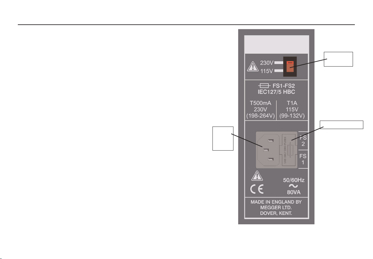
Voltage
Selector
Fuseholders
Mains
power
input
Mains Input Panel
4.
Page 5

Preparing the Oil Test Set
Operation
Ensure that the instrument is properly earthed. The test set must
be connected to a socket (receptacle) with a protective earth
(ground) conductor.
Before connecting the instrument to the mains power supply,
ensure the voltage selector located on the mains input panel is
set to the required voltage. The correct fuse value should be
fitted for the supply voltage (See
holders are located next to the supply inlet.
Power cord
If the power cord plug is not suitable for your type of socket
outlets, do not use an adaptor. You should use a suitable
alternative power cord, or if necessary change the plug by cutting
the cord and fitting a suitable plug.
The colour code of the cord is:
Earth (Ground) Yellow / Green
Neutral Blue
Phase (Line) Brown
If using a fused plug, a 3 Amp fuse to BS 1362 should be fitted.
Note: A plug severed from the power cord should be destroyed,
as a plug with bare conductors is hazardous in a live socket
outlet.
Specification). The fuse
Oil Sampling
The relevant test specification will give advice on the best
methods to use when sampling oil. Contamination of the oil may
lead to misleading results. Always run off a small amount of oil
before sampling and ensure that the flow of oil is steady.
Preparing the Oil Test Vessel
Optional vessels are available for testing to national
specifications (See table and Accessories). Some
specifications require stirring of the oil sample as well as different
test electrode shapes. Once the correct vessel has been chosen
for the required test the electrode gap should be set. This is
achieved by adjusting the threaded nut on the side of the vessel.
Small adjustment of the gap can be made by hand tightening the
nuts and rotating the spindle. A slot is provided on the end of the
spindle for this purpose.
A set of individual 0,5mm feeler gauges is provided for accurate
measurement of the gap. Gauges can be combined to measure
from 1mm to 4mm. (see page 12)
Clean the vessel in accordance with the instructions given in the
relevant test specification. Allowing space for the lid to be fitted,
fill the vessel with the oil sample. The amount of oil required will
depend upon the type of lid used. Load the vessel in the test
chamber, connecting the motor power cable, if fitted, and
carefully shut the door so that the safety interlock switch
operates.
5
Page 6

Main
controls
HV on
indicator
Control Panel
LED
Display
Ramp rate
selection
Mains
on/off
switch
Control Panel
The control panel contains the supply on/off switch, the high
voltage display, voltage ramp rate selection and the three control
keys. The operation of the instrument is very simple. When the
instrument is turned on, the on/off switch is illuminated, and the
software edition code will be flashed up on the display.
Breakdown Testing
The suitable ramp rate for the test to be performed should be
selected using the ‘s' key. The START key ‘ ‘ will then turn on
the high voltage. The red H.V. indicator will light to show the
output voltage is on. The voltage will then increase at the
selected ramp rate and the corresponding value will be shown on
the display. If oil breakdown occurs the instrument will detect this
and immediately shut off the high voltage. The breakdown
voltage value will be left on the display until the next test is
started. If no breakdown occurs, the high voltage will rise to
60 kV. At this point the test voltage is cut off and this maximum
value left on the display.
A test can be stopped at any time by pressing the
button. This will remove the high voltage from the oil sample and
leave the display at
Withstand Testing
A Withstand (proof) test can be carried out by pressing the
PAUSE ‘ ‘ key. This will maintain the high voltage at the current
value for one minute. After this time the high voltage will continue
to rise until one of the following:-
1) Oil breakdown occurs
2) The STOP ‘
0,0 kV.
key is pressed
n'
s
STOP ‘
n’
6.
Page 7
3) The output voltage reaches the maximum value of the test set.
During withstand testing the ramp rate can be changed while the
pause is in progress. This can allow the withstand test value to be
accurately set by adjusting the ramp rate to the lowest value.
Warning Messages
Door Open
If the instrument overheats, the words ‘ ‘ and
‘ ‘ will be alternately displayed and the
operation disabled. This will reset automatically,
when cooled, after a few minutes.
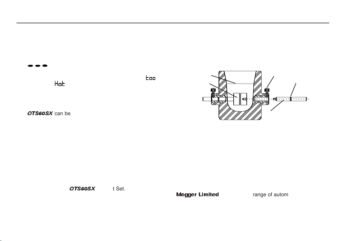
Dismantling the vessel
1. Loosen both white locking screws.
2. Hold each electrode in turn, and unscrew, and remove the
sliding arm from each electrode.
3. Remove both electrodes from the vessel.
4. Wash hands, and clean and dry the vessel as specified in
ASTM D.877.
Fill level
Electrode
Locking
screw
Viton
(Oil resistant)
‘O’ Ring
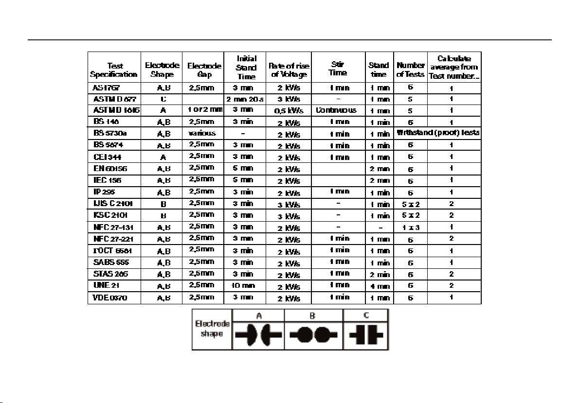
Testing to National Standards
The
OTS60SX
can be used to test to any international standard.
A table of the standards is given on page 10. To perform these
tests it is necessary to select the correct vessel so that the
specified electrodes and suitable stirring are used. Most standards
require repetitive breakdown tests to be carried out and the
average taken. Note that sometimes the first breakdown result is
omitted from the average calculation. If continuous stirring is not
required the stirrer motor supply can be disconnected when
appropriate by opening the chamber door.
100 ml Oil Test Vessel
The D877 Low Volume Test Vessel is an optional accessory for
use with the Megger®
OTS60SX
Oil Test Set.
The test vessel must be kept scrupulously clean. Before each
use, dismantle the test vessel, clean and dry, re-assemble, and
set the electrode gap to 2,54 mm (0.100 inch).
Sliding arm
Re-assembling the vessel
1. With clean, uncontaminated hands, place the cleaned
electrodes in the vessel.
2. Position each electrode in turn with the fingers, and screw
in a sliding arm through the vessel into the each electrode
in turn.
3. Centre the electrodes, and set the gap, using the
appropriate gauge.
4. Ensuring that the Viton ‘O’ rings are not fouled, hand tighten
both locking screws.
Megger Limited
also supply a range of automatic oil test sets.
These have the parameters of a wide range of specifications
programmed into the instrument for unattended operation.
7
Page 8

Sampling and Testing Oil for Dielectric Strength
The following notes should be read in conjunction with the relevant
oil testing specifications.
Causes of Bad Oil
Transformers and switchgear oil may be rendered unsuitable for
further use due to four main reasons:-
1. Low dielectric strength.
2. High acidity.
3. High sludge content.
4. Excessive free water content.
Low dielectric strength may result from many causes, the most
common of which is foreign particles or fibres and water in
combination. Individually their effect may be relatively small, but
together a contamination of only a few parts in a million can cause
considerable lowering of the breakdown voltage of the oil. High
acidity, sludge and free water should not be tolerated, but will not
necessarily reduce the dielectric strength below acceptable or
specified levels.
Appearance of the Sample
Only an experienced person can judge the condition of an
insulating oil from its appearance, but a general guide may be
obtained from the following observations:-
1. A cloudy appearance may indicate that sludge has
been formed.
2. A dark yellow colour could be a sign of overheating.
3. A blackish colour often results from an arc having taken
place with either carbonisation of the oil or of the
insulation within the equipment.
4. A green colour may be due to copper salts dissolving
in the oil.
Cleanliness of the Apparatus
The necessity for scrupulous cleanliness in the apparatus and
during the process of sampling, cannot be over emphasised. The
measurement of the dielectric strength of the sample is as
dependent on the cleanliness of the test cell and the sampling
apparatus as the condition of the oil itself.
After cleaning the apparatus, it should under no circumstances be
wiped, dried or even handled with a dusty or fibrous cloth as loose
dust or fibres are liable to cause contamination.
Precautions Necessary During Sampling
Since the oil taken from a drain cock will inevitably contain an
excess of settled out solid impurities, and will not necessarily be
representative of the bulk of the oil, it should be run to waste until
clear.
Always run off a quantity of oil into a glass bottle or a test tube for
an initial check on the appearance of the oil. Attention to this point
may prevent contamination of a clean test vessel.
If necessary, thoroughly clean and dry the sample point using a
suitable solvent. Any cloth used should be lint free. Open the
sample cock and drain to waste enough oil to ensure that the
sample cock is fully flushed and the sample is representative of
the bulk of oil to be tested. This quantity will depend upon the size
of the transformer or main container. About 2 litres is usually
suitable.
When sampling from a drum or supply container, the oil should
flow at a steady rate into the test vessel and after being swilled
around the sides it should be discarded. Without altering the rate
of flow of the oil the quantity required for the test should then be
8
Page 9

run off while taking extreme care to prevent the ingress of
atmospheric dust, cloth fibres or moisture.
Do not use a syphon. In the absence of a useable sample point,
use a ‘thief’.
Shield the sample from direct light until ready to be tested.
Turbulence and air bubbles should be avoided when pouring the
oil. Relevant national specifications should be observed.
Particular care to prevent contamination is necessary when a
test is to be made on a bulk delivery tanker, and on all occasions
when a high value of dielectric strength is anticipated. The
procedure suggested above should be rigorously applied.
9
Page 10
Oil Testing Specifications
2.54mm
Continuous/None
Continuous/None
10
Page 11

Specification
Output voltage 0 - 60 kV rms
Test Frequency 61,8 Hz
Transformer rating 500 VA
Output disconnection Within 1 ms of detection of breakdown
Power supply 115 V (99 - 132 V), 230 V (198 - 264 V) (switch selectable) 50/60 Hz, 80 VA
Fuses 500 mA (T) HBC to IEC127/5 for 220/240 V supply
1 A (T) HRC to IEC127/5 for 110/120 V supply
Mains power cord fused plug (when applicable): 3 Amp to BS1362
Operation Semi automatic with 0,5, 2 or 3 kV/s selectable rate of voltage rise
Pause function with automatic 1 minute timer for Withstand testing
Display 0,0 - 60,0 kV LED digital display
HV on LED
Ramp rate LED
Measurement Accuracy 2% ± 3 digits
Controls Start, Pause, Stop, Ramp Rate select and Power On/Off switch
Safety The instrument meets the requirements of IEC 61010-1
EMC In accordance with IEC 61326-1
Operational uncertainties Refer to www.megger.com
Temperature Range Operating: 0 to 40 ºC
Humidity Range Operating: 80% RH at 40 ºC
Dimensions 336 mm (13,2 in) (H) x 400 mm (5,7 in) (L) x 235 mm (9,3 in) (D)
Weight 17,5 kg (38,5 lb)
Cleaning Wipe disconnected test set with a clean cloth dampened with soapy water or Isopropyl Alcohol (IPA)
Storage: -40 to +70 ºC
Storage: 93% RH at 40 ºC, 95% RH at 25 ºC
11
Page 12
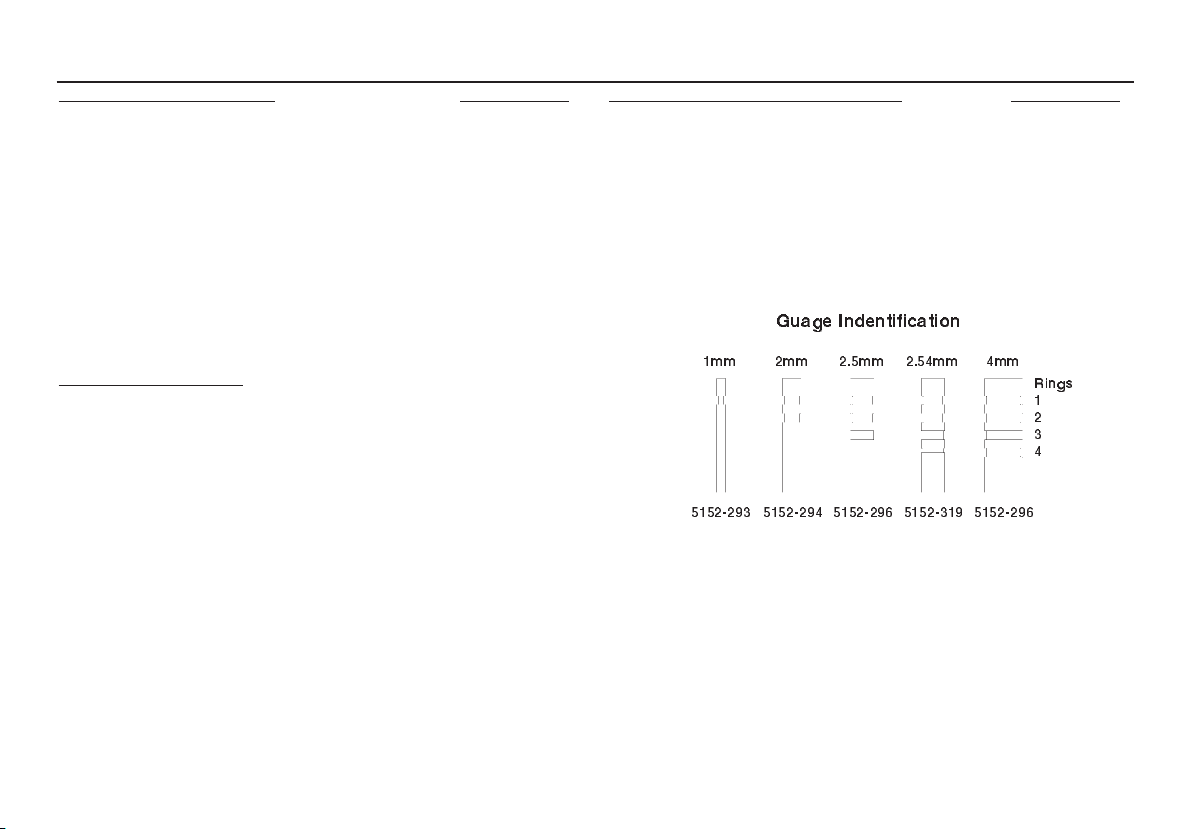
Accessories
Supplied with Instrument Part Number
User Guide 6172-120
Spacing Gauge (0,5, 1,0, 1,5, 2,0, 2,5, 2,54 & 4mm) 6132-009
Accessory Pouch 6320-232
Fuses:
2 x 500 mA (T) for 230 V supply
(fitted to the instrument) 25950-014
2 x 1 A (T) for 115 V supply 25950-004
Mains lead (fit your own plug) 25424-860
Mains lead with US plug 25970-002
Optional Accessories
Carrying Case 6420-106
Test Vessels
0,5 l for IEC156 (spherical electrodes) 6320-233
0,5 l for IEC156 with stirrer (spherical electrodes) 6320-236
0,5 l for VDE0370 (mushroom electrodes) 6320-234
0,5 l for ASTM D1816 with stirrer
(mushroom electrodes) 6320-237
0.15 litre vessel with cylindrical electrodes
for ASTMD 877 6111-356
Spare electrodes for 0.5 L vessels Part Number
Spherical (12,7 mm, 0,5 in. dia.) 6220-484
Mushroom (36 mm dia.) 6220-580
Cylindrical (25,4 mm, 1 in. dia.) 6220-483
Cylindrical with 0,5 mm edge radius 6220-538
Guage Indentification
1mm 2mm 2.5mm 2.54mm 4mm
Rings
1
2
3
4
5152-293 5152-294 5152-296 5152-319 5152-296
12
Page 13

Repair and Warranty
The instrument circuit contains static sensitive devices, and care
must be taken in handling the printed circuit board. If the
protection of an instrument has been impaired it should not be
used, and be sent for repair by suitably trained and qualified
personnel. The protection is likely to be impaired if, for example,
the instrument shows visible damage, fails to perform the
intended measurements, has been subjected to prolonged
storage under unfavourable conditions, or has been exposed to
severe transport stresses.
New Instruments are Guaranteed for 1 Year from the Date of
Purchase by the User.
Any unauthorized prior repair or adjustment will
Note:
automatically invalidate the Warranty.
Instrument Repair and Spare Parts
For service requirements for Megger Instruments contact:
Megger LImited or Megger
Archcliffe Road Valley Forge Corporate Center
Dover 2621 Van Buren Avenue
Kent, CT17 9EN. Norristown, PA 19403
England. U.S.A.
Tel: +44 (0) 1304 502243 Tel: +1 (610) 676-8579
Fax: +44 (0) 1304 207342 Fax: +1 (610) 676-8625
Approved Repair Companies
A number of independent instrument repair companies have been
approved for repair work on most Megger
instruments, using genuine Megger spare parts. Consult the
Appointed Distributor / Agent regarding spare parts, repair
facilities and advice on the best course of action to take.
Returning an Instrument for Repair
If returning an instrument to the manufacturer for repair, it should
be sent freight pre -paid to the appropriate address. Acopy of the
Invoice and of the packing note should be sent
simultaneously by airmail to expedite clearance through
Customs. A repair estimate showing freight return and other
charges will be submitted to the sender, if required, before work
on the instrument commences.
or an approved repair company.
13
Page 14

Contenu User Guide - p2 Gebrauchsanleitung - s24 Guía del usuario - p34
Avertissments relatifs a la securité 15
Description générale
Préparation du boîtier d'essai d'huile 17
Fonctionnement 17
Echantillonnage d'huile 17
Préparation du récipient d'huile 17
Panneau de commande 18
Essai de claquage 18
Essai de résistance (Epreuve) 18
Témoins d’affichage 19
Essais selon les normes nationales 19
Echantillonnage et essai de résistance
diélectrique des huiles 20
Spécifications essai des huiles 22
Réparation et Garantie 23
16
14
Page 15

GAVERTISSEMENTS RELATIFS A LA SECURITE
• Les avertissements et précautions concernant la sécurité doivent être lus et compris avant de commencer
à utiliser l'instrument. Ils doivent être observés pendant l'emploi.
• Le boîtier d'essai d'huile doit être correctement mis à la masse.
• La chambre d'essai doit être conservée scrupuleusement propre.
• Le boîtier d'essai ne doit pas être utilisé si le couvercle de la chambre d'essai est fissuré ou endommagé
d'une manière quelconque, auquel cas il doit être renvoyé à un agent autorisé pour réparation.
• Les charnières de la porte de la chambre sont équipées de ressorts de mise à la masse. Ces ressorts ne
doivent pas être endommagés ou rouillés.
• Le type correct de récipient d'essai d'huile doit être utilisé, et positionné correctement sur les guignols de
support
• Les fusibles de remplacement doivent être du type et de la puissance corrects.
avant d'effectuer un essai quelconque.
REMARQUE
CONFIEZ L’UTILISATION DE CET INSTRUMENT A UN PERSONNEL QUALIFIE ET COMPETENT.
Symboles utilisés sur cet instrument:
G Attention: Consultez les notes jointes.
F Risque de choc électrique
c Cet équipement respecte les directives en viguer de l’UE
15
Page 16

Description générale
Le modèle OTS60SX est un boîtier d'essai de résistance
diélectrique des huiles, léger et semi-automatique. L'instrument
convient à un usage en service protégé et peut être alimenté à partir
de toute une gamme de tensions secteur. La puissance de sortie
maximale de 60 kV permet d'effectuer des mesures sur des huiles de
diverses installations électriques, y compris les transformateurs, les
disjoncteurs et autres équipements. L'exploitation du boîtier d'essai
est extrêmement simple, et les résultats sont affichés sur un
affichage clair à LED. Une sélection de récipients permet de
configurer l'instrument pour une variété d'essais.
Le fonctionnement semi-automatique permet la réalisation de tous
les types d'essais. Une minuterie automatique d'une minute se
déclenche lorsque la haute tension est mise en pause pour les essais
d'épreuve (résistance). Des échantillons d'huile peuvent aussi être
testés selon des spécifications de claquage en employant une
séquence appropriée d'essais.
L'instrument est monté dans un boîtier robuste en tôle d'acier, muni
de poignées pour faciliter le transport. Une pochette est prévue sur le
côté de l'instrument pour le rangement des accessoires tels que le
cordon d'alimentation, des électrodes supplémentaires et la jauge
d'espacement. Une valise de transport avec bandoulière est
disponible en option.
Des récipients convenant aux essais d'une gamme étendue de
spécifications nationales sont disponibles. Trois types d'électrodes
sont disponibles: sphérique (type IEC), à champignon (VDE/ASTM
D1816) et cylindrique (ASTM D877). Dans certains récipients,
l'échantillon d'huile peut être agité par une turbine motorisée. Le
récipient est situé en haut de l'instrument et est couvert par une porte
en polycarbonate transparent munie d'un grillage de manière à ce
que le claquage de l'huile puisse être constaté. Une sécurité assure
la coupure de la haute tension lorsque la porte de la chambre est
ouverte.
16
Selecteur
de tension
Fusibles
Connecteur
de ligne
CEI
Panneau de alimentation secteur
Page 17

Préparation du boîtier d'essai d'huile
Vérifier que l'instrument est correctement mis à la masse. Le
boîtier d'essai doit être branché dans une prise femelle ayant un
conducteur de mise à la masse (terre).
Avant de brancher l'instrument sur le secteur, vérifier que le
sélecteur de tension, situé sur le panneau d'entrée
d'alimentation, est bien réglé à la tension requise. En outre, un
fusible de valeur adaptée à la tension d'alimentation (voir
spécifications) doit être installé. Les porte-fusibles sont situés à
côté de l'entrée de l'alimentation.
Cordon électrique de recharge de batterie
Si la prise de ce cordon ne peut pas s'enficher dans l'une de
vos prises murales, vous ne devez pas utiliser d'adaptateur.
Vous devez employer un cordon électrique de type approprié
ou, le cas échéant, retirer la prise du cordon en tranchant ce
dernier avant d'y fixer une prise de type approprié.
Ce cordon respecte le code de couleurs suivant:
Terre (masse) jaune/vert
Neutre bleu
Sous tension marron
Si vous utilisez une prise protégée par un fusible, vérifiez qu'il
s'agit d'un fusible de 3 A conforme à la norme BS 1362.
Remarque: après avoir retiré du cordon la prise électrique en
la tranchant, mettez cette dernière au rebut car une prise
comportant des conducteurs dénudés présente un danger en
cas de branchement sur une prise murale sous tension.
Fonctionnement
Echantillonnage d'huile
La spécification d'essai appropriée fournira des conseils quant
aux meilleures méthodes à employer pour le prélèvement d'un
échantillon d'huile. La contamination de l'huile peut conduire à
des résultats erronés. Laisser toujours couler une petite quantité
d'huile avant de prélever l'échantillon et veiller à ce que
l'écoulement d'huile soit constant.
Préparation du récipient d'huile
Divers récipients optionnels sont disponibles pour les essais
selon les spécifications nationales (voir tableau et ‘Accessoires‘).
Certaines spécifications exigent l'agitation de l'huile ainsi que
différentes formes d'électrodes. Lorsque le récipient correct est
choisi pour l'essai requis, l'écartement des électrodes doit être
ajusté. Ce réglage est effectué à l'aide de l'écrou fileté sur le côté
du récipient. Un jeu de jauges d’espacement, de 0,5 mm
chacune, est fourni pour la verification de l’ecartement des
electrodes. Les jauges permettent de mesurer un ecartement
entre 1 mm et 4mm.
Nettoyer le récipient conformément aux instructions fournies
dans les spécifications d'essai concernées. Tout en prévoyant un
espace pour l'installation du couvercle, verser l'échantillon
d'huile dans le récipient. La quantité d'huile requise sera fonction
du type de couvercle utilisé. Placer le récipient dans la chambre
d'essai, en branchant, le cas échéant, le câble du moteur, et
fermer soigneusement la porte de manière à actionner
l'interrupteur de sécurité.
17
Page 18

Fonctionnement (suite)
Commandes
principales
Voyant HT
en service
Panneau de commande
Affichage
LED
Sélection
de taux
d’augmentation
de tension
Interrupteur
Sous/Hors
tension
Panneau de commande
Le panneau de commande comporte l'interrupteur de mise
sous/hors tension, l'affichage haute tension, un sélecteur de taux
d'augmentation de tension et trois touches de commande.
L'exploitation de l'instrument est extrêmement simple. Lorsque
l'instrument est sous tension, l'interrupteur marche/arrêt s'allume
et le code de version du logiciel clignote sur l'affichage.
Essai de claquage
Le taux d'augmentation de tension approprié à l'essai à exécuter
doit être sélectionné en utilisant la touche 's'. La touche marche
s
' ' appliquera la haute tension. Le voyant rouge HT s'allumera
pour indiquer que la haute tension est appliquée. La tension
augmentera alors au taux sélectionné, et la valeur
correspondante sera affichée. L'instrument détecte le claquage
de l'huile et coupe immédiatement la haute tension. La valeur de
la tension de claquage reste affichée sur l'instrument jusqu'au
début de l'essai suivant. Si le claquage ne se produit pas, la
haute tension monte jusqu'à
est coupée et cette valeur maximum reste affichée.
Un essai peut être interrompu à tout moment en appuyant sur la
touche STOP ‘
tension à l'échantillon d'huile, et l'affichage revient à 0,0 kV.
Essai de résistance (Epreuve)
Un essai de résistance (Epreuve) peut être effectué en appuyant
sur la touche de
tension à la valeur courante pendant une minute, après quoi la
haute tension continuera à augmenter jusqu'à ce que :
1) l'huile claque
. Cette touche coupe l'application de la haute
n'
PAUSE ‘ ‘. Cette action maintient la haute
60 kV. En ce point, la haute tension
18
Page 19

2) le bouton STOP ‘n‘ (Arrêt) est pressé
3) la tension de sortie atteint la valeur maximum du boîtier
d'essai.
Pendant l'essai de résistance, le taux d'augmentation peut être
modifié pendant la pause. Ceci permet de régler avec précision
la valeur d'essai de résistance en ajustant le taux
d'augmentation à sa valeur la plus basse.
Témoins d’affichage
Porte ouverte
Essais selon les normes nationales
L'appareil
selon n'importe quelle norme internationale. Les normes sont
indiquées au tableau de la page 22. L'exécution de ces essais
exige la sélection du récipient correct de manière à ce que les
électrodes spécifiées et l'agitation appropriée puissent être
utilisées. La majorité des normes spécifient des essais de
claquage répétitifs, puis le calcul de la moyenne. Il convient de
noter que parfois le premier résultat de claquage est omis du
calcul. Si une agitation continue est requise, l'alimentation du
moteur de l'agitateur peut être déconnectée en ouvrant la porte
de la chambre.
OTS60SX
peut être utilisé pour effectuer des essais
En cas de surchauffe de l'instrument, les mots
' ' (trop) et ' ' (chaud) sont affichés alter-
nativement et l'opération est abandonnée.
L'instrument se remet à zéro automatiquement
une fois qu'il s'est refroidi après quelques minutes.
Megger Limited
boîtiers d'essai automatiques. Les paramètres d'une gamme
étendue de spécifications sont programmés dans l'appareil pour
assurer le fonctionnement automatique.
fournit également toute une gamme de
19
Page 20

Echantillonnage et essai de résistance diélectrique des huiles
Ces notes doivent être lues conjointement aux spécifications
d’essai d’huile appropriées.
Causes des mauvaises huiles
L’huile de transformateur et d’appareillage de commutation peut
être devenir inutilisable à cause de quatre raisons :
1. Faible résistance diélectrique
2. Forte acidité
3. Haute teneur en boues
4. Teneur excessive en eau libre
La faible résistance diélectrique a de nombreuses causes, la plus
courante étant la présence de particules étrangères ou d’une
combinaison de fibres et d’eau. Individuellement, leurs effets
peuvent être relativement faibles, mais ensemble une
contamination de quelques parties par million peut causer une
réduction considérable de la tension de claquage de l’huile. Une
forte acidité, les boues et l’eau libre ne doivent pas être tolérées,
mais ne réduiront pas la résistance diélectrique en dessous des
niveaux acceptables ou spécifiés.
Aspect de l’échantillon
Seule une personne compétente peut juger l’état d’une huile
d’isolement à partir de son aspect, mais une indication générale
peut être déduite des observations suivantes :
1. Un aspect nuageux peut indiquer la formation de boues.
2. Une couleur jaune sombre peut indiquer un échauffement
excessif.
3. Une couleur noirâtre est souvent le résultat d’un arc avec soit
carbonisation de l’huile ou de l’isolement à l’intérieur du
matériel.
4. Une teinte verdâtre peut être causée par la dissolution
desels de cuivre dans l’huile.
Propreté des appareils
La nécessité d’une propreté scrupuleuse des appareils et pendant
l’échantillonnage ne peut pas être suffisamment soulignée. La
mesure de la résistance diélectrique de l’échantillon dépend tout
aussi bien de la propreté de la cellule d’essai que de l’état même
de l’huile.
Une fois nettoyé, l’appareil ne doit jamais être essuyé, séché ou
même manipulé avec un chiffon poussiéreux ou fibreux étant
donné que les poussières ou les fibres libres peuvent causer une
contamination.
Précautions à prendre pendant l’échantillonnage
Etant donné que l’huile prélevée à partir d’un robinet de
prélèvement contiendra inévitablement une forte teneur
d’impuretés solides décantées, et ne sera pas nécessairement
représentative de la masse de l’huile, il convient de laisser couler
l’huile dans un bac de déchet jusqu’à ce qu’elle soit claire.
Laisser toujours couler une certaine quantité d’huile dans une
bouteille en verre ou dans une éprouvette pour effectuer une
inspection initiale de l’aspect de l’huile. Cette observation peut
éviter la contamination d’un récipient d’essai propre.
Si nécessaire, nettoyer et sécher le point d’échantillonnage en
utilisant un solvant approprié. Tout chiffon utilisé doit être du type
non pelucheux. Ouvrir le robinet de prélèvement et laisser couler
l’huile pour s’assurer que le robinet est totalement rincé et que
l’échantillon est représentatif de la masse d’huile à tester. Cette
quantité est fonction de la taille du transformateur ou du récipient
principal. En règle générale, 2 litres suffisent.
20
Page 21

Pour le prélèvement dans un fût ou dans un réservoir
d’alimentation, l’huile doit couler à un débit uniforme dans le
récipient d’essai, puis répandue sur les parois du récipient et jetée.
Sans modifier le débit, prélever ensuite la quantité d’huile requise
pour l’essai tout en prenant soin de pas laisser entrer de poussière
atmosphérique, de fibres de chiffon ou d’humidité. Ne pas utiliser
de siphon. En l’absence d’un point de prélèvement adéquat,
utiliser une louche.
Protéger l’échantillon de la lumière directe jusqu’à ce qu’il soit
testé.
Eviter toute turbulence ou bulles d’air lors du versement de l’huile.
Observer les spécifications nationales appropriées.
21
Page 22

Spécifications essai des huiles
2.54mm
continue/aucun
continue/aucun
22
Page 23

Réparation et Garantie
Les circuits de boîtier d'essai contiennent des éléments sensibles
à l’electricite statique et il y a lieu de prendre des précautions en
manipulant la carte de circuits imprimes. Si la protection d’un
instrument s’est trouvee affectée de quelque maniére il ne doit
pas être utilisé et doit être expeedié pour réparation par du
personnel convenablement formé et qualifié. La protection de
l’appareil peut s’être trouvée endommagée si par exemple
l’instrument apparaît visiblement abîmee, ne donne pas les
performances attendues, s’est trouvé entreposé de façon
prolongée dans des conditions défavorables ou a été exposé a
des contraintes extrêmes durant son transport.
Les nouveaux instruments sont garantis pendant une
période d’un an à partir de la date de leur achat par
l’utilisateur.
Note:
Toute réparation ou tout réglage préalable non autorisé
invalidera automatiquement la garantie.
Réparation d’instruments et pièces de rechange
Pour le service des instruments Megger®prendre contact soit:
avec ou
Megger Limited Megger
Archcliffe Road Z.A. Du Buisson de la Couldre
Dover 23 rue Eugène Henaff
Kent CT17 9EN 78190 TRAPPES
Angleterre France
Tél: +44 (0) 1304 502234 Tél: +33 (1) 30.16.08.90
Télécopie: +44 (0) 1304 207342 Télécopie: +33 (1) 34.61.23.77
ou avec une societe d’entretien agréée.
Societés d’entretien agréées
Un certain nombre de sociétés indépendantes de reparation
d’instruments ont êté agréées pour faire des opérations de
réparation sur la plupart des produits Megger utilisant des pièces
d’origine Megger
.
Consultez le distributeur désigné / agent officiel
concernant la fourniture de pièces de rechange, les installations
de réparation et pour être conseillé concernant les meilleures
mesures à prendre.
Renvoi D’un Instrument Pour le faire Réparer
Si un boîtier d'essai est réexpédiê au fabricant pour être reparé il
doit être envoyé port payé a l’adresse appropriée. Un exemplaire
de la facture et la note d’envoi doivent être envoyé par avion au
même moment afin de hâter les formalités de douane. Un devis
estimé des réparations indiquant les frais de réexpedition et
autres frais sera si nécessaire adressé a l’expéditeur avant que
les opérations de réparation ne soient enterprises.
23
Page 24

Inhalt User Guide - p2 Guide de l’utilisateur - 14 Guía del usuario - p34
Sicherheitshinweise 25
Allgemeine Beschreibung 26
Ölprüfgerät vorbereiten 27
Betrieb 27
Entnahme von Ölproben 27
Vorbereitung des Ölprüfbehälters 27
Steuertafel 28
Prüfung der Durchschlagsspannung 28
Überlastprüfung 28
Meldungen auf der Anzeige 29
Prüfungen nach nationalen Standards 29
Entnahme von Ölproben und Prüfung der
Durchschlagsfestigkeit des Öls 30
Öltest-Normen 32
Reparaturen und Garantie 33
Auf dem Gerät verwendete Symbole
In Bedienungsanleitung nachsehen
Elektroschockgefahr
Gerät entspricht den gegenwärtigen
Richtlinien der EU
24
Page 25

SICHERHEITSHINWEISE
• Die Sicherheitshinweise und Warnungen müssen vor Gebrauch des Instruments gelesen und
verstanden und beim Gebrauch beachtet werden.
• Das Ölprüfgerät muß ordnungsgemäß geerdet werden.
• Die Prüfkammer muß absolut sauber gehalten werden.
• Wenn die Abdeckung der Prüfkammer in irgendeiner Weise gerissen oder beschädigt ist, darf das
Prüfgerät nicht verwendet, sondern
muß zur Reparatur an eine autorisierte Vertretung gesendet
werden.
• Die Angeln der Kammertür sind mit Erdkontaktfedern ausgestattet, die nicht beschädigt oder
korrodiert sein dürfen.
• Es muß die richtige Art von Prüfbehälter verwendet und richtig auf den Trägerhörnern aufgestellt
werden, bevor eine Prüfung durchgeführt wird.
• Beim Austausch von Sicherungen muß die richtige Klasse und Sorte verwendet werden.
DAS INSTRUMENT DARF NUR VON ENTSPRECHEND AUSGEBILDETEN UND KOMPETETEN PERSONEN VERVENDET WERDEN.
HINWEIS
25
Page 26

Allgemeine Beschreibung
Das OTS60SX ist ein leichtes halbautomatisches Gerät zum
Prüfen der Durchschlagfestigkeit von Öl. Das Instrument ist für
geschützte praxisnahe Versuche geeignet und läßt sich an
verschiedene Stromquellen anschließen. Der Ausgang von
maximal 60 kV ermöglicht Ölprüfungen für eine große Anzahl
elektrischer Anlagen wie Transformatoren, Schutzschalter und
anderer Ausrüstung. Das Prüfgerät ist extrem einfach zu
bedienen. Die Prüfergebnisse werden auf einer hellen LEDAnzeige dargestellt. Mit Hilfe verschiedener Behälter läßt sich
das Gerät für eine Vielzahl von Prüfungen konfigurieren.
Durch den halbautomatischen Betrieb können alle Arten von
Tests durchgeführt werden. Wenn die Hochspannung für eine
Stehstoß- oder Überlastprüfung unterbrochen wird, aktiviert sich
nach einer Minute ein automatischer Zeitschalter. Durch eine
geeignete Prüfsequenz lassen sich Ölproben außerdem auf die
jeweils vorgegebene Durchschlagspannung prüfen.
Das Instrument ist in einem Gehäuse aus solidem Stahlblech
untergebracht. Zum leichteren Transport sind Griffe angebracht.
Zubehör wie das Netzkabel, zusätzliche Elektroden und der
Abstandsmesser können in einem Beutel an der Seite des
Gerätes verstaut werden. Auf Wunsch ist außerdem ein
Tragekoffer mit Schulterriemen erhältlich.
Um eine große Zahl verschiedener Prüfungen nach den
jeweiligen Vorgaben eines Landes zu ermöglichen, ist eine
Vielzahl geeigneter Behälter erhältlich. Es können drei Arten von
Elektroden geliefert werden: kugelförmig (nach IEC), halbrund
(VDE/ASTM D1816) und zylinderförmig (ASTM D877). Die
Ölprobe kann von einem motorgetriebenen Propeller umgerührt
werden, der für bestimmte Behälter erhältlich ist. Das Gefäß
selber befindet sich in der Oberseite des Instruments und wird
von einer durchsichtigen Tür aus Polycarbonat mit Drahtschirm
abgedeckt, durch die der Durchschlag beobachtet werden kann.
Beim Öffnen der Tür wird die Hochspannung durch einen
Sicherheitsschalter unterbrochen.
Netzspannungs-
eingang
Spannungs-
regler
Sicherungshalter
Haupteingangstafel
26
Page 27

Ölprüfgerät vorbereiten
Betrieb
Auf ordnungsgemäße Erdung des Gerätes achten. Das
Prüfgerät muß an eine Steckdose (Buchse) mit Schutzerdung
(Masse) angeschlossen werden.
Vor dem Anschluß des Instruments an den Netzstrom
Spannungsregler der Haupteingangstafel auf die gewünschte
Stromspannung stellen. Sicherstellen, daß die richtige Sicherung
für die jeweilige Netzspannung verwendet wird (siehe
Technische Daten). Die Sicherungshalterungen befinden sich
neben dem Netzeingang.
Netzanschlußkabel für Batterieladung
Bitte benutzen Sie keinen Adapter, wenn der Stecker des
Netzanschlußkabels nicht für ihre Steckdose geeignet ist.
Der Farbcode des Kabels ist:
Erde (Masse) Gelb/Grün
Nulleiter Blau
Außenleiter Braun
Bitte verwenden Sie eine 3-Ampere-Sicherung für Stecker mit
Sicherung.
Bitte beachten Sie: Ein Stecker sollte zerstört werden, wenn
er vom Stromkabel abgetrennt ist, da ein Stecker mit blanken
Leitern in einer stromführenden Steckdose gefährlich ist.
Entnahme von Ölproben
In den Spezifikationen zu den jeweiligen Prüfungen sind
Hinweise über die besten Methoden zur Ölprobenentnahme
enthalten. Durch verunreinigtes Öl können die Ergebnisse
verfälscht werden. Vor der Probenentnahme muß das Öl daher
stets einen Moment lang laufen gelassen werden. Außerdem ist
auf einen gleichmäßigen Ölfluß zu achten.
Vorbereitung des Ölprüfbehälters
Für Prüfungen nach den jeweiligen nationalen Vorgaben sind als
Zubehör geeignete Behälter erhältlich (siehe Tabelle und
Zubehör). Bei einigen Vorgaben ist ein Umrühren des Öls oder
ein Einsatz von Prüfelektroden in verschiedenen Formen
erforderlich. Nach der Auswahl des richtigen Behälters für die
Prüfung muß der Elektrodenabstand eingestellt werden, indem
die Gewindemutter an der Seite des Behälters gedreht wird.
Zur genauen Messung des Abstands wird ein Satz
verschiedener Fühllehren von 0,5 mm mitgeliefert, die zur
Messung von Abständen zwischen 1 und 2,5 mm miteinander
kombiniert werden können.
Der Behälter muß unter Beachtung der Anleitung zur jeweiligen
Prüfung gereinigt werden. Öl in Behälter einfüllen und darauf
achten, daß genug Platz für den Deckel verbleibt. Wieviel Öl
benötigt wird, hängt von der Art des verwendeten Deckels ab.
Behälter in Prüfkammer setzen, Stromkabel des Motors (wenn
vorhanden) anschließen und Tür vorsichtig schließen, bis sich
der Sicherheitsschalter einschaltet.
27
Page 28

Hauptregler
Hochspannungs-
anzeige
LED Anzeige
Wähler der linearen
Spannungssteilheit
Netzschalter
Steuertafel
Auf der Steuertafel befinden sich der Netzschalter, die
Hochspannungsanzeige, der Wähler der linearen
Spannungssteilheit und die drei Kontrolltasten. Das Instrument
ist äußerst einfach zu bedienen. Bei eingeschaltetem Gerät ist
der Netzschalter erleuchtet. Beim Einschalten des
OTS60SX
blinkt auf der Anzeige die Nummer der Softwareversion.
Prüfung der Durchschlagsspannung
Die für den Test geeignete lineare Spannungssteilheit wird über
die Taste ‘▲‘ gewählt. Über die Starttaste ‘ ‘ wird die
▲
Hochspannung anschließend eingeschaltet. Durch die
aufleuchtende rote Hochspannungsanzeige wird signalisiert,
daß die Ausgangsspannung eingeschaltet ist. Die Spannung
steigt dann mit der gewählten Steilheit, während der jeweilige
Wert auf der Anzeige dargestellt wird. Wenn der Durchschlag
des Öls auftritt, wird er vom Instrument registriert, das daraufhin
die Hochspannung sofort abschaltet. Die ermittelte
Durchschlagspannung wird auf dem Bildschirm angezeigt, bis
mit dem nächsten Test begonnen wird. Wenn kein Durchschlag
auftritt, steigt die Hochspannung bis auf
60 kV, woraufhin die
Prüfspannung abgeschaltet und dieser Maximalwert auf der
Anzeige dargestellt wird.
Durch Drücken der Taste ’
’ kannn die Überprüfung jederzeit
■
abgebrochen werden. In einem solchen Fall wird die
Hochspannung aus der Ölprobe entfernt, und die Anzeige zeigt
0,0 kV.
28
Steuertafel
Überlastprüfung
Eine Stehstoß- oder Überlastprüfung wird durch Drücken der
Page 29

Pausetaste ‘ ‘in Gang gesetzt. Die zu diesem Zeitpunkt
erreichte Spannung bleibt eine Minute lang bestehen.
Anschließend steigt die Hochspannung an, bis einer der
folgenden Fälle eintritt:-
1) Durchschlagspannung des Öls wird erreicht
2) Stoptaste wird gedrückt
3) Die Ausgangsspannung erreicht den Maximalwert des
Gerätes.
Bei der Überlastprüfung läßt sich die lineare Spannungssteilheit
verändern, solange die Pause andauert. Auf diese Weise läßt
sich der Wert der Überlastprüfung durch Wählen der niedrigsten
linearen Spannungssteilheit genau ermitteln.
Meldungen auf der Anzeige
Tür offen
Bei überhitztem Instrument erscheinen auf der
Anzeige abwechselnd die Wörter ‘ ‘ und ‘ ‘
und der Betrieb wird unterbrochen. Wenn das
Gerät nach einigen Minuten abgekühlt ist, endet
dieser Zustand automatisch.
Prüfungen nach nationalen Standards
Mit dem OTS60SX kann nach allen internationalen Standards
geprüft werden. Eine Tabelle der Standards befindet sich auf
Seite 32. Für diese Prüfungen müssen die richtigen Behälter
ausgewählt werden, um einen Einsatz der passenden
Elektroden und Rührvorrichtungen zu ermöglichen. Bei den
meisten Standards werden wiederholte Durchschlagsprüfungen
verlangt, aus denen anschließend der Mittelwert errechnet wird.
Der erste ermittelte Durchschlagswert wird allerdings zuweilen
nicht zur Berechnung herangezogen. Wenn kein kontinuierliches Rühren erforderlich ist, läßt sich die Stromversorgung
des Rührmotors auf Wunsch durch Öffnen der Kammertür
unterbrechen.
Megger Limited bietet außerdem eine Auswahl automatischer
Ölprüfsätze an, die mit den Parametern zahlreicher
Spezifikationen programmiert sind und einen unbeaufsichtigten
Betrieb erlauben.
29
Page 30

EEnnttnnaahhmmee vvoonn ÖÖllpprroobbeenn uunndd PPrrüüffuunngg ddeerr DDuurrcchhsscchhllaaggssffeessttiiggkkeeiitt ddeess ÖÖlls
s
Die folgenden Hinweise richten sich in erster Linie an Bediener,
die mit der Materie noch nicht vollkommen vertraut sind, und
sollten zusammen mit den entsprechenden technischen Daten
zur Ölprüfung gelesen werden.
Unbrauchbares Öl und seine Ursachen
Es gibt vier hauptsächliche Ursachen, aus denen das Öl von
Transformatoren und Schaltvorrichtungen unbrauchbar werden
kann
1. Geringe Durchschlagsfestigkeit
2. Hoher Säuregehalt
3. Hoher Schlammgehalt
4. Zuviel nichtgebundenes Wasser
Eine geringe Durchschlagsfestigkeit kann auf verschiedene
Ursachen zurückzuführen sein, von denen Fremdkörper oder
Fasern in Verbindung mit Wasser am häufigsten auftreten. Für
sich alleine genommen wirken sie sich nur geringfügig aus;
zusammengenommen jedoch können sie bereits bei einer
Verunreinigung von wenigen Teilchen pro Millionen zu einer
beachtlichen Verringerung der Durchschlagsspannung des Öls
führen. Ein hoher Säure- oder Schlammgehalt des Öls sollte
ebensowenig toleriert werden wie nichtgebundenes Wasser;
diese Merkmale verringern jedoch die Durchschlagsfestigkeit
nicht zwangsläufig unter einen akzeptablen oder
vorgeschriebenen Stand.
Aussehen der Probe
Nur erfahrene Bediener können vom Aussehen eines Isolieröls
auf dessen Zustand schließen. Als generelle Anhaltspunkte
können jedoch die folgenden Richtlinien dienen:
1. Ein trübes Aussehen läßt auf Schlammbildung schließen.
2. Eine dunkelgelbe Färbung kann auf Überhitzungzurückzuführen sein.
3. Eine schwärzliche Färbung wird oft dadurch verursacht,
daß sich ein Lichtbogen gebildet hat und entweder das Öl
oder die Isolierung des Gerätes karbonisiert ist.
4. Eine grüne Färbung weist auf im Öl gelöste Kupfersalze
hin.
Sauberkeit des Instruments
Es kann nicht genug betont werden, wie wichtig es ist, beim
Betrieb des Geräts und während der Probenentnahme auf
peinlichste Sauberkeit zu achten. Welche Durchschlagsfestigkeit
bei der Probe gemessen wird, hängt genauso von der Sauberkeit
der Prüfzelle und des Probengeräts wie vom Zustand des Öls
selber ab.
Das Gerät darf nach der Reinigung auf keinen Fall mit einem
staubigen oder fusseligen Tuch abgewischt, getrocknet oder
auch nur angefaßt werden, da loser Staub oder Fusseln leicht zu
Verunreinigungen führen.
Vorsichtsmaßnahmen bei der Probenentnahme
Wenn das Öl über einen Ablaßhahn gewonnen wird, enthält es
30
Page 31

unweigerlich zu viele abgelagerte Verunreinigungen und ist u. U.
für das übrige Öl nicht repräsentativ. Das Öl sollte daher so
lange abfließen, bis es klar wird.
Beim Ausgießen des Öls sind Erschütterungen oder Luftblasen
zu vermeiden und die jeweiligen nationalen Bestimmungen
einzuhalten.
Für eine erste Überprüfung des Aussehens sollte ein Teil des Öls
stets in einer Glasflasche oder einem Reagenzglas aufgefangen
werden. Auf diese Weise wird eine unnötige Verunreinigung
sauberer Prüfgefäße vermieden.
Wenn nötig, muß die Prüfspitze mit einem geeigneten
Bei einer Probenentnahme aus Lieferungen von Tankfahrzeugen
und bei allen anderen Gelegenheiten, bei denen eine hohe
Durchschlagsfestigkeit zu erwarten ist, muß mit besonderer
Sorgfalt vorgegangen und das oben beschriebene Verfahren
genau eingehalten werden.
Lösungsmittel gereinigt und anschließend mit einem fusselfreien
Tuch getrocknet werden. Ablaßhahn öffnen und soviel Öl
ablaufen lassen, daß der Hahn vollständig gespült wird und die
Probe für das übrige Öl repräsentativ ist. Wieviel Öl abgelassen
werden muß, hängt von der Größe des Transformators oder
Hauptbehälters ab. In der Regel sind etwa 2 Liter ausreichend.
Bei der Entnahme von Proben von einem Faß oder
Versorgungsbehälter sollte das Öl mit gleichmäßiger
Geschwindigkeit in das Prüfgefäß fließen. Anschließend wird das
Öl um die Seiten des Gefäßes geschwenkt und fortgeschüttet.
Ohne Veränderung der Fließgeschwindgkeit wird dann die für die
Prüfung erforderliche Menge entnommen, wobei das Eindringen
von Staub, Tuchfasern oder Feuchtigkeit unbedingt zu vermeiden
sind. Siebe dürfen nicht verwendet werden. Wenn kein
geeignetes Probenstück vorhanden ist, kann ein Pegelstab
benutzt werden.
Die Probe muß bis zur Prüfung lichtgeschützt aufbewahrt
werden.
31
Page 32

Öltest-Normen
Test
Spezifikation
AS1767 A,B 2,5 mm 3 min 2 kV/s 1 min 1 min 6 1
ASTM D877 C 2,54 mm 2 min 20 s 3 kV/s - 1 min 5 1
ASTM D 1816 A 1 or 2 mm 3 min 0,5 kV/s Kontinuität 1 min 5 1
BS 148 A,B 2,5 mm 3 min 2 kV/s 1 min 1 min 6 1
BS 5730a A,B Verschiedene - 2 kV/s 1 min 1 min
BS 5874 A,B 2,5 mm 3 min 2 kV/s 1 min 1 min 6 1
CEI 344 A 2,5 mm 3 min 2 kV/s 1 min 1 min 6 1
EN 60156 A,B 2,5 mm 3 min 2 kV/s
IEC 156 A,B 2,5 mm 3 min 2 kV/s
IP 295 A,B 2,5 mm 3 min 2 kV/s 1 min 1 min 6 1
IJIS C 2101 B 2,5 mm 3 min 3 kV/s - 1 min 5 x 2 2
KSC 2101 B 2,5 mm 3 min 3 kV/s - - 5 x 2 2
NFC 27-131 A,B 2,5 mm 3 min 2 kV/s - - 1 x 3 1
NFC 27-221 A,B 2,5 mm 3 min 2 kV/s 1 min 1 min 6 2
„OCT
SABS 555 A,B 2,5 mm 3 min 2 kV/s 1 min 1 min 6 1
STAS 286 A,B 2,5 mm 3 min 2 kV/s 1 min 2 min 6 2
UNE 21 A,B 2,5 mm 10 min 2 kV/s 1 min 4 min 6 2
VDE 0370 A,B 2,5 mm 3 min 2 kV/s 1 min 1 min 6 1
Elektroden
form
A,B 2,5 mm 3 min 2 kV/s 1 min 1 min 6 1
Elektroden-
abstand
Anfangsstandzeit
Ansteigsrate
der
Prüfspannung
Rührzeit Standzeit
Kontinuität/Keine
Kontinuität/Keine
Anzahl
der Tests
2 min 6 1
2 min 6 1
Errechne Mittelwert
aus Test Nummer.....
Durchschlagsprüfung
32
Page 33

Reparaturen und Garantie
Das Instrument enthält statisch empfindliche Bauteile, weshalb
die gedruckte Schaltung sorgfältig behandelt werden muß. Falls
die Schutzvorrichtungen eines Instruments beschädigt worden
sind, sollte es nicht verwendet, sondern an eine geeignete
Reparaturwerkstatt geschickt werden. Die Schutzvorrichtungen
sind wahrscheinlich beschädigt, wenn folgende Bedingungen
vorliegen: sichtbare Beschädigung, fehlende Anzeige der
erwarteten Meßergebnisse; längere Lagerung unter widrigen
Bedingungen oder starke Transportbelastung.
NEUE INSTRUMENTE UNTERLIEGEN EINER
GARANTIE VON 1 JAHR AB DEM DATUM DES
KAUFS DURCH DEN BENUTZER.
Hinweis:
Einstellung führt automatisch zum Erlöschen der Garantie.
Reparaturarbeiten und Ersatzteile
Wenden Sie sich zwecks Wartungsarbeiten an Megger®-
lnstrumenten entweder an:
Megger Limited oder an Megger
Archcliffe Road Valley Forge Corporate Center
Dover 2621 Van Buren Avenue
Kent CT17 9EN Norristown, PA 19403
England USA
Tel: +44(0)1304 502100 Tel: +1 (610) 676-8579
Fax: +44(0)1304 207342 Fax: +1 (610) 676-8625
Jede nicht zuvor genehmigte Reparatur oder
Autorisierte Reparaturfirmen
Eine Reihe von Firmen sind für die Reparatur der meisten
Megger
Ersatzteilen autorisiert. Wenden Sie sich wegen Ersatzteilen,
Reparaturwerkstatten und Beratung über die jeweils
bestgeeigneten Maßnahmen an eine autorisierte Auslieferung
bzw. Vertretung.
Einsenden Eines Instruments Zur Reparatur
Wenn ein Instrument zwecks Reparatur zurück geschickt
werden muß, sollte es mit vorbezahiter Fracht an die
angebrachte Anschrift gesandt werden. Gleichzeitig sollte zur
Erledigung der britischen Zollformalitäten per Luftpost eine
Kopie der Rechnung zusammen mit dem Packzettel eingesandt
werden. Auf Wunsch wird dem Absender vor Ausführung
irgendwelcher Arbeiten am Instrument ein Kostenvoranschlag
unter Berücksichtigung der Frachtkosten und anderer
Gebühren zugesandt.
- lnstrumente unter Verwendung von Original Megger-
oder an eine autorisierte Reparaturfirma.
33
Page 34

Contenido User Guide - p2 Guide de l’utilisateur - p14 Gebrauchsanleitung - s24
Advertencias de Seguridad 35
Descripción general 36
Preparación del aparato de pruebade Aceite 37
Operación 37
Muestreo de aceite 37
Preparación del recipiente de prueba de aceite 37
Panel de control 38
Prueba de descomposición 38
Mensajes visualizados 39
Especificaciones por la Prueba de Aceites 42
Prueba de conformidad con las normas nacionales 39
Reparacione y Garantia 43
34
Page 35

GADVERTENCIAS DE SEGURIDAD
• Las precauciones y advertencias de seguridad deben leerse y comprenderse antes de utilizar el instrumento.
• El aparato de prueba debe estar conectado a tierra correctamente.
• La cámara de prueba debe mantenerse escrupulosamente limpia.
• Si la tapa de la cámara está agrietada o dañada de cualquier manera no debe usarse el aparato de prueba sino
que deben enviarse para su reparación a un agente autorizado.
• Las bisagras de la puerta de la cámara incorporan muelles de contacto a tierra. Estos muelles no deben dañarse
ni oxidarse.
• Debe usarse el tipo correcto de recipiente de prueba de aceite, el cual debe colocarse en los salientes de soporte
antes de llevar a cabo cualquier prueba.
• Los fusibles de repuesto deben ser del tipo y régimen correctos.
NOTA
EL INSTRUMENTO SOLO SERA UTILIZADO POR PERSONAS CAPACITADAS Y COMPETENTES.
Símbolos usados en el instrumento
G Referirse a la Guía del usuario
F Riesgo de sacudida eléctrica
c El equipo está conforme con las directrices actuales de la UE
35
Page 36

Descripción general
El OTS60SX es un instrumento para la prueba de resistencia
dieléctrica, semiautomático y de peso liviano. El instrumento es
apropiado para uso en campo protegido y puede ser impulsado a
través de una gama de suministros de la red. La salida máxima de
60 kV permite realizar pruebas en aceite procedente de una
amplia variedad de instalaciones eléctricas, incluidos transformadores, disyuntores y equipos parecidos. El funcionamiento del
aparato es sumamente sencillo y los resultados son presentados
en un brillante display por LED. Una selección de recipientes
permite configurar el instrumento para una variedad de pruebas.
El funcionamiento semiautomático del instrumento permite
realizar todos los tipos de pruebas. Un temporizador de un minuto
automático funciona cuando se interrumpe el voltaje alto para la
prueba de resistencia. Las muestras de aceite también pueden
probarse de acuerdo con la especificación de descomposición
utilizando una secuencia de pruebas adecuada. El instrumento
está construido dentro de una recia caja de chapa de acero. El
aparato incorpora asas para facilitar su transporte. Se incluye una
bolsa en el lateral del instrumento para alojar accesorios tales
como el cable eléctrico, electrodos adicionales y el calibre
espaciador. Una caja de transporte opcional incluye un tirante
para colgar sobre el hombro. Hay disponible cierto de recipientes
para realizar pruebas de acuerdo con una amplia variedad de
especificaciones nacionales. Se incluyen tres tipos de electrodos:
esférico (tipo IEC), en forma de seta (VDE/ASTM D1816) y
cilíndrico (ASTM D877). La muestra de aceite puede agitarse con
una hélice impulsada por motor disponible en recipientes
seleccionados. El recipiente se coloca en la parte superior del
instrumento y se cubre mediante una puerta de policarbonato
transparente con pantalla de malla, de modo que puede
observarse la descomposición del aceite. Un dispositivo de
enclavamiento asegura que el alto voltaje sea desconectado
cuando se abre la puerta de la cámara.
Conector de
Alimentation
Selector
de
Voltage
Porto
fusibles
Panel de entrada de la red
36
Page 37

Preparación del aparato de pruebade Aceite
Asegure que el instrumento esté correctamente conectado a
tierra. El aparato de prueba debe conectarse a una toma
(receptáculo) con un conductor de protección a tierra (masa).
Antes de conectar el instrumento al suministro de la red, asegure
que el selector de voltaje situado en el panel de entrada de la red
esté situado en el voltaje requerido. También deberá instalarse
el fusible del régimen correcto para el voltaje de suministro (vea
especificaciones). Los portafusibles están situados
las
adyacentes a la entrada del suministro.
Cable de alimentación
Si el cable de alimentación no es compatible con la toma
eléctrica, no use ningún adaptador. Emplee un cable de
alimentación adecuado, o si es necesario, cambie el enchufe
cortando el cable e instalando uno idóneo.
El código de los colores del cable es el siguiente:
Tierra Amarillo/Verde
Neutro Azul
Fase Marrón
Si el enchufe tiene un fusible integrado, utilice uno que sea de 3
Amp y que cumpla con la norma BS 1362.
Nota: deseche el enchufe cortado del cable ya que su uso puede
ser peligroso.
Operación
Muestreo de aceite
Las especificaciones de prueba pertinentes aportarán consejos
sobre los mejores métodos que deben utilizarse para el
muestreo de aceite. La contaminación del aceite puede conducir
a resultados engañosos. Deje escapar siempre una pequeña
cantidad de aceite antes de muestrear y asegure que el aceite
fluye de manera uniforme.
Preparación del recipiente de prueba de aceite
Hay recipientes opcionales para probar de acuerdo con las
especificaciones nacionales (vea la tabla y accesorios). Ciertas
especificaciones requieren el agitado de la muestra de aceite así
como diferentes formas de electrodos de prueba. Una ves
seleccionado el recipiente correcto para la prueba requerida
deberá establecerse el entrehierro del electrodo, lo cual se logra
ajustando la tuerca roscada situada en el costado del recipiente.
Se incluye un juego de galgas palpadoras individuales de 0,5mm
para la medición precisa del entrehierro. Las galgas pueden
combinarse para medir de 1 a 2,5mm.
Limpie el recipiente de acuerdo con las instrucciones incluidas
en las especificaciones pertinentes. Dejando espacio para
colocar la tapa, llene el recipiente con la muestra de aceite. La
cantidad de aceite requerida dependerá del tipo de tapa
utilizada. Ponga el recipiente en la cámara de prueba,
conectando el cable eléctrico del motor, si se incluye, y cierre
con cuidado la puerta, de modo que funcione el interruptor de
enclavamiento de seguridad.
37
Page 38

Controles
principales
Indicador
de alto
voltaje
Panel de control
Display
LED
Selector de
promedio de
rampa
Interruptor de
conexión/
desconexión de la
red
Panel de control
El panel de control contiene el interruptor de conexión /
desconexión de suministro, display de alto voltaje, selector de
promedio de rampa de voltaje y las tres teclas de control. El
funcionamiento del instrumento es muy sencillo. Cuando se
conmuta el instrumento el código de la edición del software
parpadeará en el display et se enciende el interruptor de
conexión/desconexión.
Prueba de descomposición
El promedio de rampa apropiado para la prueba a realizar
deberá seleccionarse usando la tecla ‘
▲
inicio ` ' conmutará entonces el alto voltaje. El indicador de alto
▲' START. La tecla de
voltaje rojo se encenderá para indicar que está conmutado el
voltaje de salida. El voltaje incrementará entonces al promedio
de rampa seleccionado y el valor correspondiente será
mostrado en el display. Si se produce descomposición del
aceite el instrumento detectará esto e inmediatamente cortará
el alto voltaje. El valor del voltaje de descomposición
permanecerá en el display hasta que se pone en marcha la
prueba siguiente. Si no se produce descomposición alguna, el
alto voltaje ascenderá a
60 kV. En este momento se corta el
voltaje de prueba y su valor máximo permanece en el display.
La prueba se podrá detener en cualquier momento pulsando el
botón
STOP ‘
■
. Con esto se retirará el alto voltaje de la
’
muestra de aceite y el display mostrará 0,0 kV.
Prueba de resistencia
Podrá efectuarse una prueba de resistencia pulsando la tecla
de pausa ` '. Con esto se mantendrá el valor corriente durante
un minuto. Después de transcurrir este tiempo, el alto voltaje
continuará ascendiendo hasta que ocurre uno de los eventos
siguientes:
38
Page 39

1) Se descompone el aceite.
2) Se pulsa el botón de parada.
3) El voltaje de salida alcanza el máximo valor del aparato
de pruebas.
Durante la prueba de resistencia el promedio de rampa puede
cambiarse mientras está en curso la pausa. Esto puede permitir
establecer precisamente el valor de prueba de resistencia
ajustando el promedio de rampa al valor más bajo.
Mensajes visualizados
Puerta abierta
Si el instrumento se calienta excesivamente,
las palabras ‘ ‘(demasiado) y ` '
(caliente) serán visualizadas de manera alterna
alternativamente y la operación será desactivada.
Una vez frío, el instrumento se reposicionará
automáticamente, después de unos minutos.
Prueba de conformidad con las normas nacionales
El OTS60SX puede utilizarse para hacer pruebas de
conformidad con cualquier norma nacional. En la página 42 se
incluye una tabla de las normas. Para realizar estas pruebas es
necesario seleccionar el recipiente correcto de modo que
puedan usarse los electrodos especificados y un agitado
adecuado. La mayoría de las normas requieren que sean
llevadas a cabo pruebas de descomposición repetidas y que
sean tomados los promedios. Nótese que algunas veces el
primer resultado de descomposición es omitido del cálculo
medio. Si no se requiere agitado continuo, el suministro al motor
agitador podrá desconectarse cuando sea apropiado abriendo la
puerta de la cámara.
Recipiente de prueba de aceite Megger D877 de 100 ml
El recipiente de prueba de bajo volumen D877 es un accesorio
opcional para ser usado con el conjunto de prueba de aceite
®
semiautomático Megger
OTS60SX. El recipiente de prueba
debe ser limpiado concienzudamente. Antes de cada uso,
desmonte, limpie, seque y rearme el recipiente, ajustando la
separación del electrodo a 2,5 mm (0.100 pulgada).
Desarmado del recipiente
1. Afloje ambos tornillos de bloqueo blancos.
2. Sujete cada electrodo por turno, y desenrosque y retire el
brazo deslizante de cada electrodo.
3. Retire ambos electrodos del recipiente.
4. Lave las manos y luego limpie y seque el recipiente como
se especifica en ASTM D.877.
Rearmado del recipiente
1. Con las manos limpias y desprovistas de contaminación,
coloque los electrodos limpios en el recipiente.
2. Coloque cada electrodo por turno con los dedos, y rosque
un brazo deslizante a través del recipiente en cada
electrodo por turno.
3. Centre los electrodos y ajuste la separación, usando una
galga apropiada.
4. Asegurando que los aros tóricos de vitón no estén sucios,
apriete ambos tornillos de bloqueo.
Megger Limited ambién suministra una gama de aparatos de
prueba de aceite automáticos. Estos instrumentos tienen
programados los parámetros de una amplia gama de especificaciones para funcionamiento sin personal.
39
Page 40

Muestreo del aceite y prueba de su resistencia dieléctrica
Las notas deberán leerse en conjunción con las especificaciones de prueba de aceite pertinentes.
Causas de aceite defectuoso
El aceite usado en transformadores y equipos de
conmutación pueden acabar siendo inservibles a causa de
cuatro motivos principales:
1. Baja resistencia dieléctrica
2. Alto contenido de acidez
3. Alto contenido de fangos
4. Contenido excesivo de agua libre
La baja resistencia dieléctrica puede producirse por muchas
causas, siendo la más común partículas extrañas o fibras y agua
combinadas. Individualmente su efecto puede ser relativamente
pequeño, pero juntos una contaminación de solamente unas
pocas partes por millón puede causar una reducción considerable
del voltaje de ruptura del aceite. Alta acidez, fangos y agua libre
no deben ser tolerados, pero no reducirán necesariamente la
resistencia dieléctrica por debajo de unos niveles aceptables o
especificados.
Aspecto de la muestra
Solamente una persona con experiencia podrá juzgar por su
aspecto la condición de un aceite aislante, pero una guía general
podrá obtenerse a través de las siguientes observaciones:
1. Un aspecto nebuloso puede indicar que se ha formado
fango.
2. Un color amarillo apagado oscuro podría ser una señal de
calentamiento excesivo.
3. Un color negruzco con frecuencia es consecuencia de
haberse formado el arco concarbonización ya sea del
aceite o bien del aislamiento dentro del equipo.
4. Un color verde puede ser debido a la presencia de sales de
cobre disueltas en el aceite.
Limpieza del aparato
La necesidad de una limpieza escrupulosa del aparato y durante
el proceso de muestreo nunca podrá subrayarse demasiado. La
medición de la resistencia dieléctrica de la muestra depende de la
limpieza de la célula de prueba y del aparato de muestreo así
como de la condición del aceite propiamente dicho.
Después de limpiar el aparato, de ninguna manera deberá ser
frotado, secado ni incluso manejado con un trapofibroso o
polvoriento, ya que el polvo y las fibras sueltas pueden causar
contaminación.
Precauciones necesarias durante el muestreo
Como el aceite tomado de un grifo de vaciado inevitablemente
contiene un exceso de impurezas sólidas depositadas, y no será
representativo de la totalidad del aceite, éste deberá dejarse fluir
al desagüe hasta que sale transparente. Vaciar siempre cierta
cantidad de aceite en una probeta o botella de vidrio para verificar
inicialmente el aspecto del aceite. Si se observa este punto se
podrá prevenir la contaminación de un recipiente de prueba
limpio. Si es necesario, limpie y seque a fondo el punto de
muestra usando un disolvente adecuado. Todos los trapos
utilizados deberán estar carentes de hilazas. Abra el grifo de
muestreo y vacíe al desagüe suficiente aceite para asegurar que
40
Page 41

el grifo de muestreo quede completamente lavado y que la
muestra sea representativa de la totalidad del aceite que se desea
probar. Esta cantidad depende del tamaño del transformador o
recipiente principal. Normalmente se vacían unos 2 litros. Cuando
se muestrea el aceite contenido en un bidón o recipiente de
suministro, el aceite deberá fluir a un promedio uniforme dentro
del recipiente de prueba y una vez circulado alrededor de los
lados deberá ser desechado. Sin alterar el promedio de flujo del
aceite, la cantidad requerida para la prueba deberá recogerse
ahora teniendo cuidado extremado de prevenir el ingreso de polvo
atmosférico, fibras de trapo o humedad. No use un sifón. Si no hay
un punto de prueba utilizable, use un `ladrón'.
Proteja la muestra contra la luz directa hasta que vaya a probarse.
Cuando se vierte el aceite deberá impedirse la formación de
burbujas de aire y turbulencia. Deberán observarse las especificaciones nacionales pertinentes al caso.Es preciso tener cuidado
especial para evitar contaminación si la prueba ha de hacerse en
un camión cisterna de suministro a granel y en todos los casos
donde se espera alto nivel de resistencia dieléctrica. El
procedimiento sugerido arriba deberá ser observado
estrictamente.
41
Page 42

Especificaciones por la Prueba de Aceites
Prueba
Especificado
AS1767 A,B 2,5 mm 3 min 2 kV/s 1 min 1 min 6 1
ASTM D877 C 2,54 mm 2 min 20 s 3 kV/s - 1 min 5 1
ASTM D 1816 A 1 or 2 mm 3 min 0,5 kV/s Continuo 1 min 5 1
BS 148 A,B 2,5 mm 3 min 2 kV/s 1 min 1 min 6 1
BS 5730a A,B varie - 2 kV/s 1 min
BS 5874 A,B 2,5 mm 3 min 2 kV/s 1 min 1 min 6 1
CEI 344 A 2,5 mm 3 min 2 kV/s 1 min 1 min 6 1
EN 60156 A,B 2,5 mm 3 min 2 kV/s
IEC 156 A,B 2,5 mm 3 min 2 kV/s
IP 295 A,B 2,5 mm 3 min 2 kV/s 1 min 1 min 6 1
IJIS C 2101 B 2,5 mm 3 min 3 kV/s - 1 min 5 x 2 2
KSC 2101 B 2,5 mm 3 min 3 kV/s - - 5 x 2 2
NFC 27-131 A,B 2,5 mm 3 min 2 kV/s - - 1 x 3 1
NFC 27-221 A,B 2,5 mm 3 min 2 kV/s 1 min 1 min 6 2
„OCT
SABS 555 A,B 2,5 mm 3 min 2 kV/s 1 min 1 min 6 1
STAS 286 A,B 2,5 mm 3 min 2 kV/s 1 min 2 min 6 2
UNE 21 A,B 2,5 mm 10 min 2 kV/s 1 min 4 min 6 2
VDE 0370 A,B 2,5 mm 3 min 2 kV/s 1 min 1 min 6 1
Forma de
Electrodo
Electro Interralo
A,B 2,5 mm 3 min 2 kV/s 1 min 1 min 6 1
Tiempo da la
Posicion Inicial
Velocidad de
subida del
voltaje
Tiempo de
movimiento
Continuo/no continco
Continuo/no continco
Teimpo de
parada
2 min 6 1
2 min 6 1
Numero
pruebas
Pruebas de resistancia
Calcuda la media de la
de
prueba numero....
42
Page 43

Reparacione y Garantia
El circuito del instrumento contiene dispositivos sensibles a la
electricidad estática y deberá tenerse cuidado cuando se maneje
el panel de circuito impreso. No deberá utilizarse ninguna
protección de un instrumento que haya sido dañada y deberá
enviarse para ser reparada por personal debidamente preparado
y capacitado. Se dañará la protección si, por ejemplo, el
instrumento muestra desperfectos visibles, no realiza las
mediciones esperadas, se ha visto sujeto a un almacenamiento
prolongado bajo condiciones desfavorables o ha estado
expuesto a presiones rigurosas de transporte.
Los instrumentos nuevos tienen una garantia de 1 año a
partir de la fecha de adquisicion del usuario.
Nota:
Cualquier ajuste o reparación no autorizada previamente
anulará automáticamente la garantía.
Reparación de Instrumentos y Piezas de Repuesto
Para un servicio de los instrumentos Megger®contacte por favor
con:
Megger Limited o Megger
Archcliffe Road, Valley Forge Corporate Center
Dover 2621 Van Buren Avenue
Kent CT17 9EN, Norristown, PA 19403
Inglaterra USA
o una compañia de reparaciones aprobada.
Companias de reparaciones aprobadas
Varias compañias independientes han sido aprobadas para
realizar trabajos de reparación de la mayoría de los instrumentos
Megger
Consulte con su Agente/Distribuidor con referencia a las pi ezas
de repuesto, facilidad es de reparación y asesoramiento sobre la
mejor línea de conducta a seguir.
Devolviendo un Instrumento Para Su Reparación
Si se devuelve un instrumento al fabricante para su reparación,
deberá enviarse a porte pagado a la dirección adecuada. Al
mismo tiempo, deberá adjuntarse una copia de la factura y de la
nota de envío, por correo aéreo, a fin de acelerar los trámites de
aduanas. Se enviará un presupuesto de reparación en el que
aparecerá la tarifa de flete de retorno y otros gastos, si procede,
antes de empezar el trabajo en el instrumento.
, utilizando auténticas piezas de repuesto Megger.
Tel.: +44 (0) 1304 502243 Tel.: +1 (610) 676-879
Fax: +44 (0) 1304 207342 Fax: +1 (610) 676-8625
43
Page 44

M
Megger Limited
Archcliffe Road Dover
Kent CT17 9EN ENGLAND
T +44 (0)1 304 502101
F +44 (0)1 304 207342
OTHER TECHNICAL SALES OFFICES
Toronto CANADA, Sydney AUSTRALIA, Madrid SPAIN, Mumbai INDIA, and the Kingdom of BAHRAIN.
Megger products are distributed in 146 countries worldwide.
This instrument is manufactured in the United Kingdom.
The company reserves the right to change the specification or design without prior notice.
Megger is a registered trademark
Part No. 6172-120 V15 Printed in England 1108
www.megger.com
Megger
4271 Bronze Way, Dallas,
TX 75237-1019 USA
T +1 800 723 2861
T +1 214 333 3201
F +1 214 331 7399
Megger
Z.A. Du Buisson de la Couldre
23 rue Eugène Henaff
78190 TRAPPES France
T +33 (1) 30.16.08.90
F +33 (1) 34.61.23.77
 Loading...