

Page 1

Baker Instruments
MTR105
Rotating Machine Tester
User Guide
Page 2

This document is copyright of:
Megger Limited, Archcliffe Road, Dover, Kent CT17 9EN. ENGLAND
T +44 (0)1304 502101 F +44 (0)1304 207342 www.megger.com
Megger Ltd reserves the right to alter the specification of its products from time to time without
notice. Although every effort is made to ensure the accuracy of the information contained within
this document it is not warranted or represented by Megger Ltd. to be a complete and up - to - date
description.
For Patent information about this instrument refer to the following web site:
http://uk.megger.com/patents
ii www.megger.com
Page 3

This manual supersedes all previous issues of this manual. Please ensure that you are using the most recent issue of this
document. Destroy any copies that are of an older issue.
Declaration of Conformity
Hereby, Megger Instruments Limited declares that radio equipment manufactured by Megger Instruments Limited
described in this user guide is in compliance with Directive 2014/53/EU. Other equipment manufactured by Megger
Instruments Limited described in this user guide is in compliance with Directives 2014/30/EU and 2014/35/EU where they
apply.
The full text of Megger Instruments EU declarations of conformity are available at the following internet address:
uk.megger.com/company/about-us/eu-dofc
www.megger.com iii
Page 4

Contents
1. Safety Warnings ........................................................................................................2
1.1 Warnings, Cautions and Notes ........................................................................................ 2
1.1.1 Warnings ........................................................................................................................ 2
1.1.2 Cautions ......................................................................................................................... 2
1.1.3 Notes .............................................................................................................................. 2
1.2 Safety warnings ................................................................................................................ 2
1.2.1 Test lead safety warnings ................................................................................................. 3
1.3 Product Safety Category - Measurement Connection .................................................... 3
1.3.1 Voltage ........................................................................................................................... 3
1.3.2 CAT IV ............................................................................................................................ 3
1.3.3 CAT III ............................................................................................................................. 3
1.3.4 CAT II .............................................................................................................................. 3
1.4 Safety, Hazard and Warning Symbols on the Instrument .............................................. 4
1.4.1 Warning Icons ................................................................................................................. 4
2. Introduction ...............................................................................................................5
2.1 Product Description .......................................................................................................... 5
2.2 Applications ...................................................................................................................... 6
2.3 Features ............................................................................................................................. 6
2.4 Company web site. ........................................................................................................... 6
2.5 Instrument Controls ......................................................................................................... 7
2.6 Instrument Display ........................................................................................................... 8
2.7 Instrument Controls.......................................................................................................... 9
2.8 Instrument Connections and Leads ................................................................................. 10
2.8.1 View on top of MTR105 .................................................................................................. 10
3. Instrument Set up ......................................................................................................11
3.1 Warnings and exception conditions ................................................................................ 11
3.2 Power ................................................................................................................................ 11
3.2.1 First use ......................................................................................................................... 11
3.2.2 Turn the instrument on and off ....................................................................................... 11
3.2.3 Power options ................................................................................................................. 12
3.3 Lockout Voltage ............................................................................................................... 12
4. Insulation Resistance Tests .......................................................................................13
4.1 Insulation test options...................................................................................................... 13
4.2 Two Terminal and Guard .................................................................................................. 13
4.3 Automatic discharge ........................................................................................................ 14
4.4 Insulation Resistance (IR) Test .......................................................................................... 14
4.4.1 Buzzer settings ................................................................................................................ 16
4.4.2 Temperature compensation ............................................................................................. 17
4.5 3 Phase (3P) ....................................................................................................................... 18
4.6 Polarization Index (PI) ...................................................................................................... 20
iv www.megger.com
Page 5

4.7 Timed (T(s))Test ................................................................................................................. 22
4.8 Dielectric Absorption Ratio (DAR) .................................................................................. 24
4.9 Variable voltage .............................................................................................................. 26
5. Voltmeter ...................................................................................................................28
5.1 TRMS (True RMS) .............................................................................................................. 28
5.2 AC or DC ........................................................................................................................... 29
5.3 Supply Phase Rotation...................................................................................................... 30
6. Continuity ..................................................................................................................32
6.1 Uni-direction ..................................................................................................................... 32
6.2 Bi-direction ....................................................................................................................... 34
6.3 Diode test .......................................................................................................................... 36
7. DLRO Digital Low Resistance Ohmmeter ................................................................38
7.1 Manual single direction test ............................................................................................ 38
7.2 Auto Single direction test ................................................................................................ 40
7.3 Manual bi-direction test................................................................................................... 41
7.4 Auto Bi direction test ....................................................................................................... 44
7.5 Test failure ...................................................................................................................... 46
7.5.1 Lost connection ............................................................................................................... 46
8. Direction of Motor Rotation .....................................................................................47
9. Inductance (L); Capacitance (C); Resistance (R) (LCR) ..............................................48
9.1 Auto .................................................................................................................................. 48
9.2 Capacitance or inductance ............................................................................................... 49
9.3 LCR Calibration ................................................................................................................. 51
10. Temperature measurement ....................................................................................54
10.1 Thermocouple temperature measurement................................................................... 54
10.2 Manual Temperature measurement .............................................................................. 56
11. Data management ...................................................................................................58
11.1 Creating a new asset ID ................................................................................................. 58
11.2 Using an existing asset ID............................................................................................... 59
11.3 Deleting an asset ............................................................................................................ 60
11.4 Deleting items from within an asset ............................................................................. 61
11.5 Deleting a single test ..................................................................................................... 63
11.6 Exporting entries to USB ................................................................................................ 65
12. Firmware update .....................................................................................................68
13. Error and Warning Conditions................................................................................70
13.1 Failed export ................................................................................................................... 70
13.2 Fuse Failure ..................................................................................................................... 70
13.3 Battery Low ..................................................................................................................... 70
14. Settings ....................................................................................................................71
14.1 IR Test Settings ................................................................................................................ 71
www.megger.com v
Page 6

14.1.1 DAR Settings ................................................................................................................. 71
14.1.2 Insulation threshold ....................................................................................................... 72
14.1.3 Lock .............................................................................................................................. 72
14.1.4 Temperature compensation ........................................................................................... 72
14.1.5 Terminal lock out ........................................................................................................... 72
14.1.6 Timed Insulation ............................................................................................................ 73
14.1.7 Variable Voltage ............................................................................................................ 73
14.2 General Settings ............................................................................................................. 73
14.2.1 Back-light timer ............................................................................................................. 73
14.2.2 Battery Technology ........................................................................................................ 73
14.2.3 Date .............................................................................................................................. 74
14.2.4 Instrument information ................................................................................................. 74
14.2.5 Key Press Notification ................................................................................................... 74
14.2.6 Sleep timer .................................................................................................................... 74
14.2.7 Time ............................................................................................................................. 75
14.2.8 Restore factory settings ................................................................................................. 75
14.3 Language settings .......................................................................................................... 75
15. Maintenance ............................................................................................................76
15.1 General Maintenance ..................................................................................................... 76
15.2 Cleaning .......................................................................................................................... 76
15.3 Battery ............................................................................................................................. 76
15.3.1 Battery status ................................................................................................................ 76
15.3.2 12 V supply ................................................................................................................... 77
15.3.3 Battery Charging ........................................................................................................... 77
15.3.4 Battery error screens .................................................................................................. 77
15.4 Battery and Fuse Replacement ...................................................................................... 78
15.4.1 Replace battery cells and remove isolation tab ............................................................... 79
15.4.2 To replace the fuses ....................................................................................................... 79
16. Specifications ...........................................................................................................80
17. Accessories and Equipment ....................................................................................83
17.1 Included Accessories ....................................................................................................... 83
17.2 Optional Accessories....................................................................................................... 83
18. Calibration, Repair and Warranty ..........................................................................84
18.1 Return procedure ........................................................................................................... 84
19. Decommissioning ....................................................................................................85
19.1 WEEE Directive ............................................................................................................... 85
19.2 Battery disposal .............................................................................................................. 85
vi www.megger.com
Page 7

www.megger.com vii
Page 8

Safety Warnings
1. Safety Warnings
The safety instructions given in this document are indicative of safe practice and are not be considered exhaustive.
Additionally, they are not intended to replace local safety procedures in the region where the instrument is used. If
the equipment is used in a manner not specified by the manufacturer, the protection provided by the equipment may
be impaired.
1.1 Warnings, Cautions and Notes
This user guide follows the internationally recognized definition of warnings, cautions and notes. These instructions
must be adhered to at all times.
1.1.1 Warnings
Warnings alert the reader to hazardous situations where injury to personnel can occur. They are set in red type
to make them stand out. They are placed before the item to which they relate and repeated at each applicable
occasion.
1.1.2 Cautions
Cautions alert the reader to situations where equipment damage may result if a process is not followed properly.
They are set in bold type. They are placed before the item to which they relate and repeated at each applicable
occasion.
1.1.3 Notes
Notes give additional important information that will help the reader. They are not used when a Warning or Caution
is applicable. They are not safety related and may be placed either before or after the associated text as required.
1.2 Safety warnings
These safety warnings must be read and understood before the instrument is used. Retain for future reference.
Warning: This instrument must be operated only by suitably trained and competent people.
Protection provided by the instrument may be impaired if it is not used in a manner specified by the
manufacturer.
Local Health and Safety Legislation requires users of this equipment and their employers to carry out valid risk
assessments of all electrical work to identify potential sources of electrical danger and risk of electrical injury such
as inadvertent short circuits. Where the assessments show that the risk is significant then the use of fused test
leads may be appropriate.
The voltage indicator and automatic discharge features must be regarded as additional safety features and not a
substitute for normal safe working practice which MUST be followed.
The circuit under test must be switched off, de-energized, securely isolated and proved dead before test
connections are made unless measuring voltage or phase rotation.
Circuit connections, exposed conductive parts and other metalwork of an installation or equipment under test
must not be touched during testing.
When inductive loads are measured it is essential that the current carrying leads are securely clamped to the item
being tested and that they are not removed before any stored charge has been discharged at the end of the test.
Failure to comply with these instructions might result in an arc being produced, which might be dangerous for
the instrument and the operator.
The Voltmeter function will operate only if the instrument is switched on and working correctly.
After an insulation test, the instrument must be left connected until the circuit has been discharged to a safe
voltage.
The instrument must not be used if any part of it is damaged or if the terminal shutter is missing.
2 www.megger.com
Page 9

Safety Warnings
All test leads, probes and crocodile clips must be in good order, clean and with no broken or cracked insulation.
Verify the integrity of the test leads before use. Only “Megger” approved test leads must be used with this
product.
The safe maximum limit of a measurement connection is that of the lowest rated component in the
measurement circuit formed by the instrument, test leads and any accessories.
Ensure that hands remain behind finger guards of probes/clips.
Replacement fuses must be of the correct type and rating. Failure to fit the correctly rated fuse will result in fire
and burns hazards and cause damage to the instrument in the event of an overload.
All covers must be in place whilst conducting tests.
This product is not intrinsically safe. Do not use in an explosive atmosphere.
Ensure every cell in the battery compartment is of identical type. Never mix rechargeable and non-chargeable
cells.
1.2.1 Test lead safety warnings
The circuit under test must be switched off, de-energized, isolated and checked to be safe before insulation test
connections are made. Make sure the circuit is not re-energized while the instrument is connected.
Test leads, including crocodile clips, must be in good condition, clean, dry and free of broken or cracked
insulation. The lead set or its components must not be used if any part of it is damaged.
The safe maximum limit of a measurement connection is that of the lowest rated component in the
measurement circuit formed by the instrument, test leads and any accessories.
The CAT III 600 V rated thermocouple probe tip and protective ring are conductive. Care must be taken when
using the probe on live systems not to short-circuit to adjacent conductors.
1.3 Product Safety Category - Measurement Connection
Only Megger supplied test leads designed for this instrument provide the full safety rating.
1.3.1 Voltage
The rated measurement connection voltage is the maximum line to earth voltage at which it is safe to connect.
1.3.2 CAT IV
Measurement category IV: Equipment connected between the origin of the low-voltage Mains Power supply and the
distribution panel.
1.3.3 CAT III
Measurement category III: Equipment connected between the distribution panel and the electrical outlets.
1.3.4 CAT II
Measurement category II: Equipment connected between the electrical outlets and the User’s equipment.
Measurement equipment may be safely connected to circuits at the marked rating or lower. The connection rating is
that of the lowest rated component in the measurement circuit.
www.megger.com 3
Page 10
i
Safety Warnings
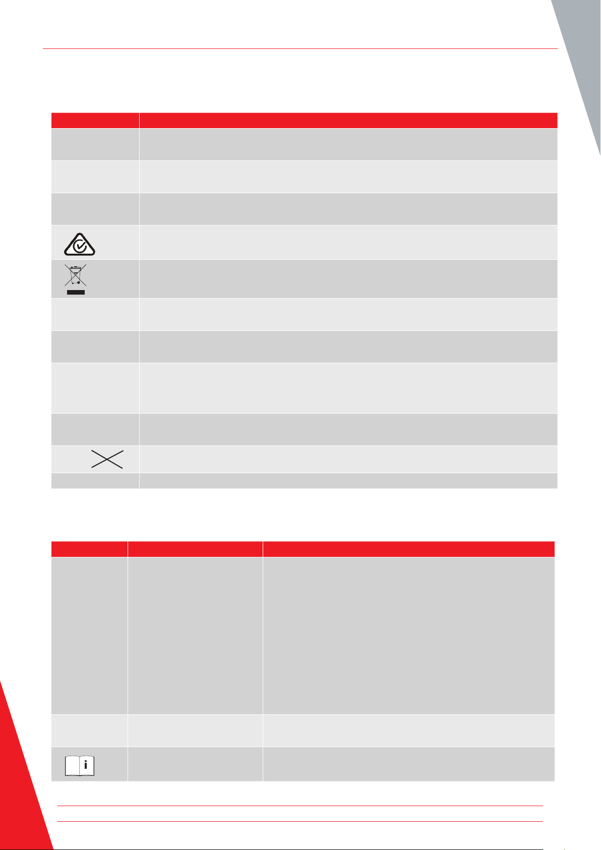
1.4 Safety, Hazard and Warning Symbols on the Instrument
This section details the various safety and hazard icons on the instruments outer case.
Icon Description
Warning: High Voltage, risk of electric shock
F
Caution: Refer to User Guide.
G
Equipment complies with current EU directives.
c
Equipment complies with current ‘C tick’ requirements.
Do not dispose of in the normal waste stream.
Equipment protected throughout by double insulation.
t
Fuse
f
CAT III
600 V
CAT rating
600 V ac RMS maximum between terminals and between terminal and earth
g
dc
d
G >1100 V
IP54 IP rating
1.4.1 Warning Icons
This section details the warning icons that can show on the display.
Icon Warning Description
F
G
Do not use in distribution systems with voltages higher than 1100 V
External Voltage Warning If an external voltage is applied between the terminals and the
instrument is set to On, the High Voltage warning will flash
on the display. This is a warning that the item under test is
live and might be dangerous and testing is disabled. The High
Voltage warning message will flash if more than 50 V potential
difference is applied between the Voltage terminals and the
Current terminals. This warning will not show if all terminals are
at the same high voltage.
NOTE: The warning will not operate if the instrument is set to
Off.
Internal Error Warning Internal Error Warning switch off and back on. Contact Megger
if not cleared.
Read the User Guide Refer to the user guide if this message shows.
4 www.megger.com
Page 11

Introduction
2. Introduction
2.1 Product Description
This user guide details the operational and functional details of the Megger MTR105 Rotating Machine Tester. Please
read this user guide fully before attempting to use the MTR105. The MTR105 instrument is designed to perform a
number tests that are typical for rotating machines.
These tests include
Insulation resistance,
Voltage measurement,
Continuity,
DLRO, digital low resistance ohmmeter - 4 wire kelvin mΩ,
Motor direction of rotation test,
Capacitance,
Inductance
Temperature.
The MTR105 is powered by six AA alkaline primary cells. As an optional accessory, rechargeable NiMH AA cells can
be used with an external power supply and adaptor to charge the batteries whilst in the instrument. Lithium primary
(not Lithium Ion) cells can also be used.
For personal safety and to get the maximum benefit from this instrument, make sure that the safety warnings and
instructions are read and understood before the instrument is used, see Refer to 1. Safety Warnings on page 2.
This user guide must be thoroughly read before attempting to operate the MTR105.
NOTE: This manual includes instructions for all MTR105 variants. Some facilities may not be available on your model
of this equipment.
The MTR105 takes the test abilities of Megger’s proven MIT400 test instruments adding; DLRO four wire tests,
inductance and capacitance to provide a versatile motor tester, all packaged in a robust hand held instrument, which
up to now has simply not been available.
In addition the MTR105 also incorporates temperature measurement and compensation (for IR tests), direction of
rotation plus supply phase rotation tests.
All these new test abilities go together to make the MTR105 a real world, versatile, hand held test instrument for
rotating machinery.
The MTR105 also comes in an over-moulded case, providing increased protection, robustness and achieving an IP54
rating against moisture and dust ingress.
Refer to the image at Refer to 2.5 Instrument Controls on page 7 for detail of the MTR105 layout.
For the safety of all personnel and to get the maximum benefit from this instrument, ensure the safety instructions of
Refer to 1. Safety Warnings on page 2 are read and thoroughly understood before the MTR105 is used.
Tests and connections detailed in this user guide are not exhaustive. Refer to the booklet Guide to Motor Testing
(published by Megger) for further information about motor testing.
www.megger.com 5
Page 12

Introduction
2.2 Applications
The MTR105 is an OFF LINE motor tester that can be used on small to medium sized rotating machines, typically up
to 500 hp.
Typical applications include but are not limited to:
New manufactured motor – test in production process.
Refurbished/Repaired motor – test in repair workshop.
Monitoring and maintenance of in service motors (off line) – workshop or in the field.
Where there is doubt about a particular application, refer to the booklet Guide to Motor Testing.
2.3 Features
Guard Terminal - to eliminate any surface leakage current.
Detachable insulation resistance test leads with interchangeable clips and probes for different applications.
Stores test results for up to 256 motors, which can be downloaded to a USB drive.
Rotary dial control and full graphic display - simple and easy to use.
Sealed to IP54, providing protection against moisture and dust ingress, including the battery and fuse
compartments.
Tough housing: A ‘rubber over moulding’ combines a tough shock absorbing outer protection with excellent
grip, on a strong modified ABS housing, providing an almost indestructible case.
Rechargeable batteries with mains charger kit option.
2.4 Company web site.
Occasionally an information bulletin may be issued via the Megger web site. This may be new accessories, new usage
instructions or a software update. Please occasionally check on the Megger web site for anything applicable to your
Megger instruments.
www.megger.com
6 www.megger.com
Page 13

2.5 Instrument Controls
2
Introduction
1
3
6
4
5
7
8
9
Item Description Item Description
1 External electrical connections 6 Save
2 Display 7 Test
3 Soft keys (multifunction) 8 Information / Lock / OK
4 Buzzer control 9 Rotary selection switch
5 Back-light control
www.megger.com 7
Page 14
Introduction
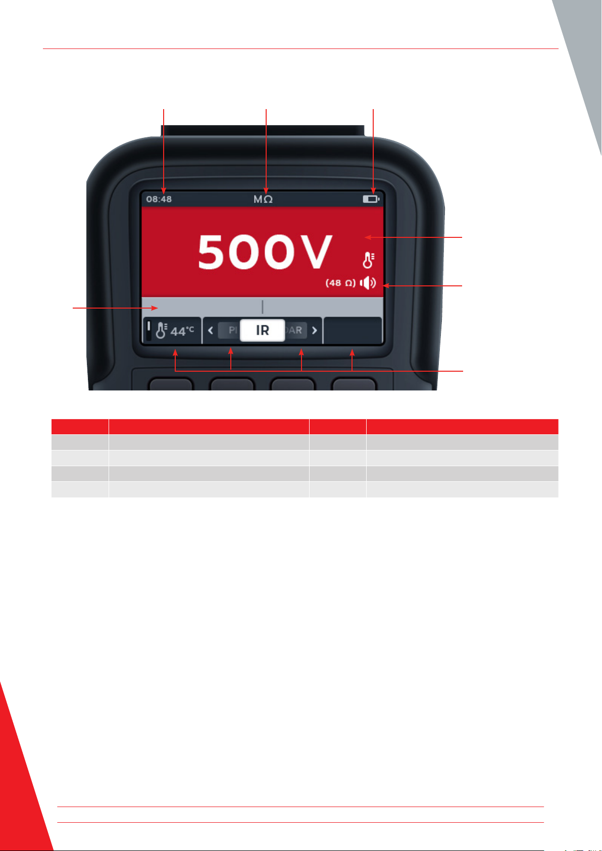
2.6 Instrument Display
7
1 2
3
4
6
5
Item Description Item Description
1 Status / Mode 5 Soft key functions
2 Battery indicator 6 Secondary field
3 Primary field 7 Time
4 Status symbols
8 www.megger.com
Page 15

2.7 Instrument Controls
Introduction
10
11
13 1412
9
8
17
6
5
4
3
2
Item Description Item Description
Rotary switch positions
1 Settings (Grey) 8 Off (Grey)
2 Data management (Blue) 9 Voltmeter, 3 phase supply, direction of
rotation and frequency (Black)
3 Temperature (White) 10 Insulation Resistance Test, 50 V (Red)
4 Inductance capacitance and resistance
11 Insulation Resistance Test, 250 V (Red)
(Green)
5 Motor direction of rotation (Light grey) 12 Insulation Resistance Test, 500 V (Red)
6 Digital Low Resistance Ohmmeter (Yellow) 13 Insulation Resistance Test, 1 kV (Red)
7 Continuity and diode test (Orange) 14 Insulation Resistance Test, user
selectable voltage (Red)
www.megger.com 9
Page 16

Introduction
2.8 Instrument Connections and Leads
2.8.1 View on top of MTR105
Slider to front Slider to back
1
2
4
1
3
6
6
Item Description Item Description
1 Rear attachment point for strap 4 Slider in rear position
2 Battery charger connection / switch probe 5 USB port
3 Slider in front position 6 Front
The external connections are all situated on top of the MTR105. A sliding cover is installed to prevent any other
connection being made at the same time as the USB port. Connection to the USB port can only be made when the
sliding cover is pushed completely to the back of the instrument.
5
For charging or connection to any test leads the sliding cover must be in the forward position.
The charger connection is designed so that no other lead can be connected while the battery is being charged in the
instrument.
10 www.megger.com
Page 17
Instrument Set up
3. Instrument Set up
Before each use of the instrument, visually inspect the instrument case, test leads and connectors to confirm their
condition is good, with no damaged or broken insulation
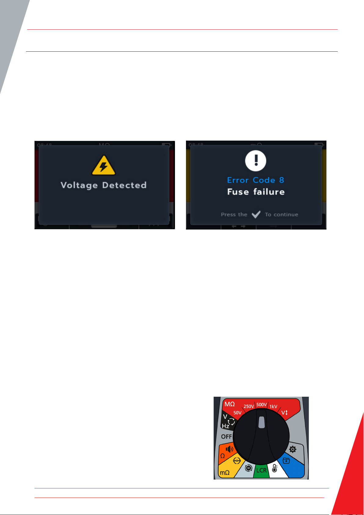
3.1 Warnings and exception conditions
There are two types of alerts that interrupt the standard process, they are the warnings for an external condition alert
and the exception condition for an internal fault alert. The alert message is overlaid on the display screen with the
fault message. The images below are examples illustrating the two types of alerts:
Alert for dangerous external fault. Alert for internal fault.
c
3.2 Power
3.2.1 First use
NOTE: Before the MTR105 can be turned on the battery isolation tab must be removed.
1. Remove the battery cover.
2. Pull the battery isolation tab clear of the battery cells.
3. Replace cover.
For further details on accessing the battery panel, Refer to 15.4 Battery and Fuse Replacement on page 78.
For initial date and time set up, Refer to 14.2.3 Date on page 74 and Refer to 14.2.7 Time on page 75.
NOTE: If the MTR should lose the date and time setting, (for example if the batteries have been replaced and the
instrument has been without them for more than 3 minutes) the instrument will display a prompt screen when
turned on to enter the date and time details - this can appear anytime after first set up.
3.2.2 Turn the instrument on and off
1. Turn the instrument ON by turning the rotary switch away
from the OFF position to activate the instrument.
www.megger.com 11
Page 18
Instrument Set up
2. Turn the instrument OFF by turning the rotary switch to the
OFF position to deactivate the instrument.
NOTE: The MTR105 switches off after a period of inactivity,
which is user adjustable, Refer to 14. Settings on page 71.
To start the instrument again rotate the mode switch to Off
and then select a mode or press the TEST button to wake the
instrument up.
3.2.3 Power options
Caution: Do not attempt to recharge alkaline or Lithium cells, this action is a high potential fire hazard.
The MTR105 is powered by Internal batteries,
These cells may be used:
6 x LR6 1.5 V Alkaline (AA)
6 x IEC HR6 1.2V NiMH
6 x IEC FR6 1.5 V Lithium (LiFeS2).
The instrument charges using the dc adapter (NiMH cells only), which will work at voltages between 100 and 240 V
ac. Charging will only occur if the battery type is set to NiMh.
Warning: Charge NiMH cells only between 0 ºC and +40 ºC ambient.
The battery cell type is selected from the settings menu, Refer to 14. Settings on page 71. It will not charge
Alkaline or LiFeS2 cells.
To charge the cells in the instrument, it has to have the mains charger kit plugged into the terminal connections.
Testing or access the USB is not possible while the instrument is being charged.
See also Refer to 16. Specifications on page 80
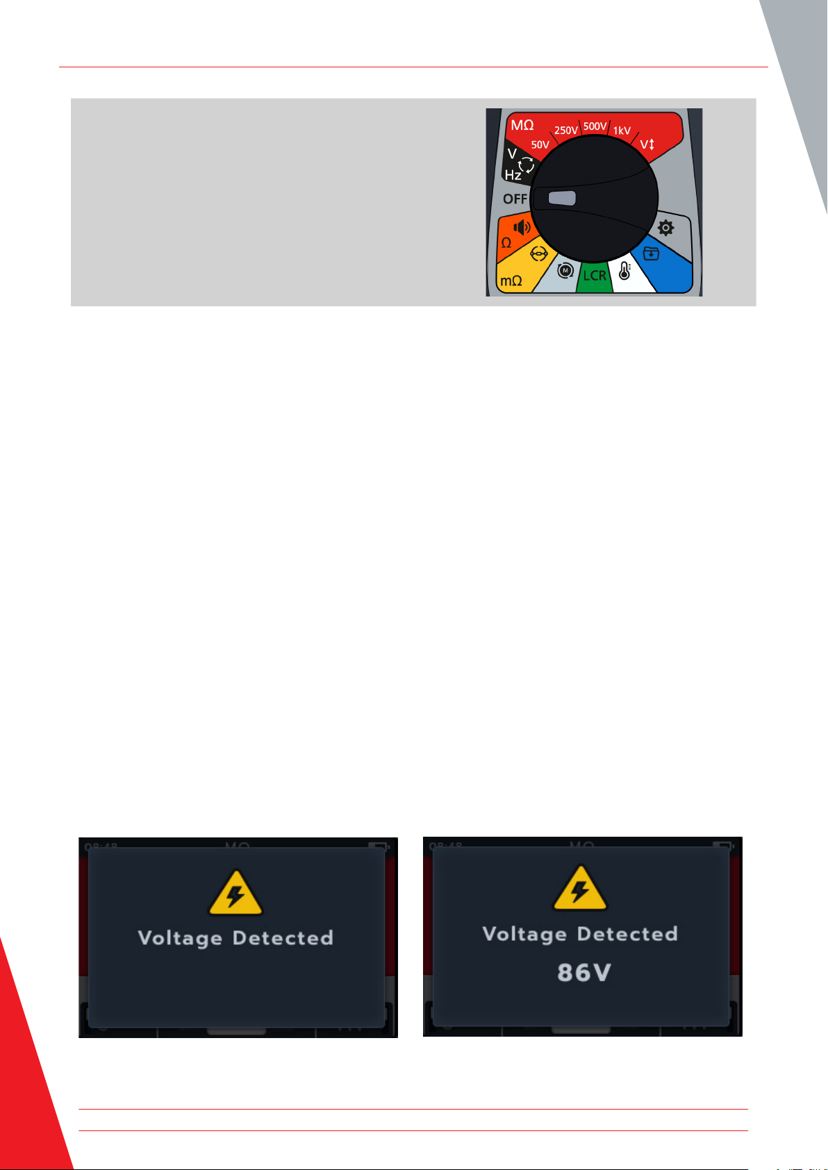
3.3 Lockout Voltage
Before testing, the measurement board will carry out a short a pre-test voltage check. If the lockout voltage is
exceeded, the user will see an overlay menu showing the current voltage measured. The overlay will disappear if the
voltage is lowered below the lockout voltage threshold.
The lockout voltage is active on all test modes. It is hard-coded to activate at 20 V. The only exception is the
insulation resistance tests, where the lockout voltage can be set in the settings (as 20 V, 30 V, 50 V or 75 V).
12 www.megger.com
Page 19
Insulation Resistance Tests
4. Insulation Resistance Tests
Warning: Hazardous voltages are emitted throughout the insulation resistance tests. Do not touch the
test leads while testing is in progress (after test button has been pressed). The warning triangle will flash
on the display during these tests.
Insulation resistance tests can be carried out at the following settings 50 V, 250 V, 500 V, 1 kV and variable voltage
(variable symbol). These are all coloured red and are positioned across the top of the rotary switch.
The test method for each voltage setting is identical.
Variable voltage is user selectable, Refer to 14. Settings on page 71. The variable voltage setting is configurable
between 10 V to 999 V.
4.1 Insulation test options
Icon Description
IR: Insulation resistance.
PI: Polarization Index is the ratio between insulation resistance values recorded at 1 minute
(assigned t1) and 10 minutes (assigned t2).
DAR: Dielectric Absorption Ratio, it is the ratio between the insulation resistance values at 15 or
30 seconds (assigned t1) and at 60 second interval (assigned t2). i.e. after 30 seconds and 60
seconds. DAR = 15 or 30 (default) second value / 60 second value
T(s): Time IR = Selectable from 1 minute to 10 minutes, in 1 minute increments.
3P 3 Phase. To test insulation resistance phase to phase.
F This warning triangle flashes when any voltage is being output in the insulation resistance test
process.
4.2 Two Terminal and Guard
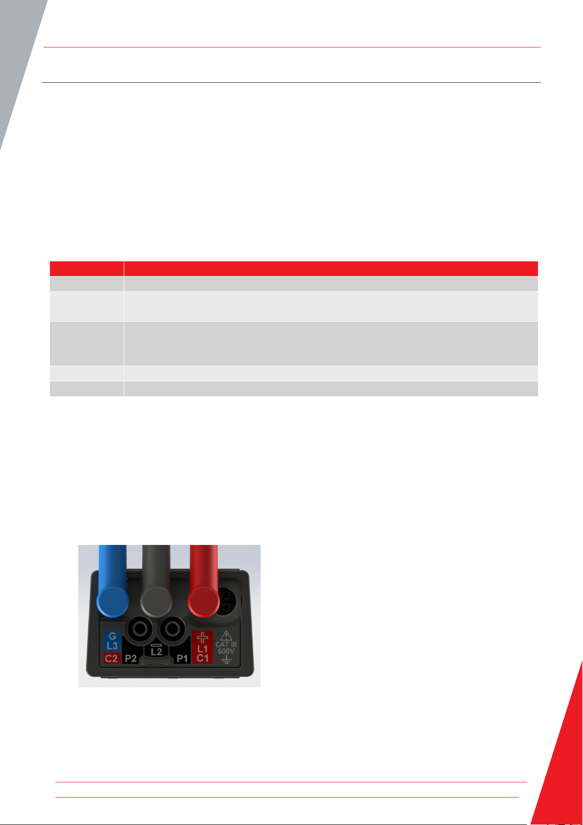
The MTR105 is fitted with a guard terminal. The guard terminal is used to conduct leakage currents away from the
measured circuit to reduce errors.
The guard terminal is only used for insulation testing and as and additional connection in 3-phase testing. The lead is
coloured blue.
The guard lead (G) is optional. When used, it should be connected to the guard conductor, screen, steel wire
armoured conductor, or “user added” conductive wire or wrapper, such as foil.
For further information refer to Guide to Motor Testing published by Megger.
www.megger.com 13
Page 20

Insulation Resistance Tests
4.3 Automatic discharge
Following any insulation test, when the TEST button is released, the discharge loop begins to discharge the test piece.
The automatic discharge loop will discharge the unit under test, removing any hazardous voltage introduced by the
insulation test.
During the automatic discharge loop, the lightening symbol will flash and the falling voltage displayed on the left of
the secondary field.
After the automatic discharge loop has finished, the secondary result is displayed in the secondary field again and the
buzzer sounds for a second.
4.4 Insulation Resistance (IR) Test
1. Connect the test leads to the MTR105.
1.1. Press the Information ( ) button to view the lead set
up diagram.
NOTE: when the diagram is displayed a test cannot be
performed. Press Information ( ) button to return to the test
screen
This test can also be performed with just the red and the black
lead.
2. Connect the test leads to the unit under test.
NOTE: The connection is for illustrative purposes only
When performing phase to phase measurements, the star or
delta configuration has to be disconnected.
3. Select the required insulation test voltage.
4. The display will show the selected voltage, in this case 500 V.
14 www.megger.com
Page 21
5. Press soft keys 2 and 3 to move the carousel left or right
through sub-modes. IR is default, scroll through to 3P, PI,
T(s) DAR.
NOTE: The full title text of the sub-mode will appear in the
secondary field for a few seconds.
6. If required, press soft key 1 to toggle between temperature
compensation on and off.
NOTE: this is only available in IR test mode.
To adjust the temperature compensation, Refer to 4.4.2
Temperature compensation on page 17
Insulation Resistance Tests
7. If required, Turn the buzzer on, off or visual as required by
pressing buzzer button. Refer to 4.4.1 Buzzer settings on
page 16
NOTE: This is only available in IR test mode.
To adjust the insulation threshold, Refer to 14. Settings on page
71
8. Start the test by pressing and holding down the TEST button.
The buzzer will sound on test initiation.
8.1. To hold the test voltage, press the LOCK button while
the TEST button is held. Once the lock symbol is
displayed and the buzzer has sounded, the TEST button
can be released. This test will continue until the TEST
button or the LOCK button is pressed to stop the test.
To enable this Refer to 14.1.3 Lock on page 72
NOTE: As the test starts the Soft Key Function field disappears,
secondary and function fields drop to the bottom of the screen.
Sub-mode initials separate the secondary fields.
www.megger.com 15
Page 22

Insulation Resistance Tests
9. During the tests,
Test results in the primary field show the IR value.
Status symbols will appear in the bottom right-hand
corner of the primary field.
The secondary field shows the actual voltage and current.
10. The test may be stopped at any time by pressing or releasing
the TEST button again
11. When the test has completed
The primary field displays the test results.
The secondary field displays actual voltage output and the
current measured.
12. To save the test result press the SAVE button. A message
will inform you the data was saved and which asset ID it was
saved to.
13. To restart the test press the TEST button again.
NOTE: To set up an asset ID Refer to 14. Settings on page 71
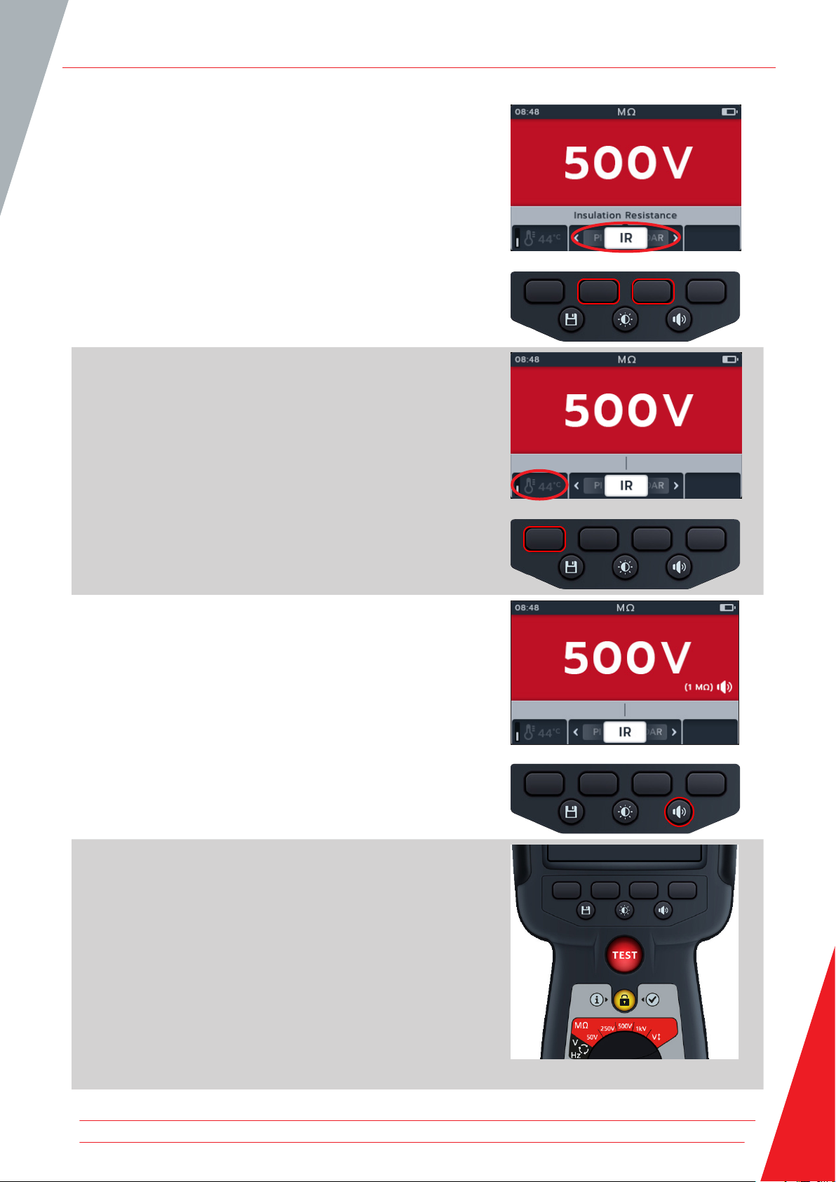
4.4.1 Buzzer settings
Set the buzzer to the preferred option before starting a test.
Buzzer status is indicated at the bottom right hand corner of
the primary field. The buzzer threshold is shown just above the
status indicator.
The buzzer has 3 options and is set by pressing the fixed key.
The options are off (default), on and optical. Press and release the buzzer key until the desired function is reached.
16 www.megger.com
Page 23
Insulation Resistance Tests
Visual indicator Description
Buzzer off.
No indication given.
Buzzer on
Buzzer will give both audio and visual on screen
indication.
Buzzer optical
Buzzer will only give a visual, on screen indication.
When running an IR test, if the threshold is exceeded the buzzer will activate and the background will flash. A pass
band is shown in the analogue scale and is highlighted in green.
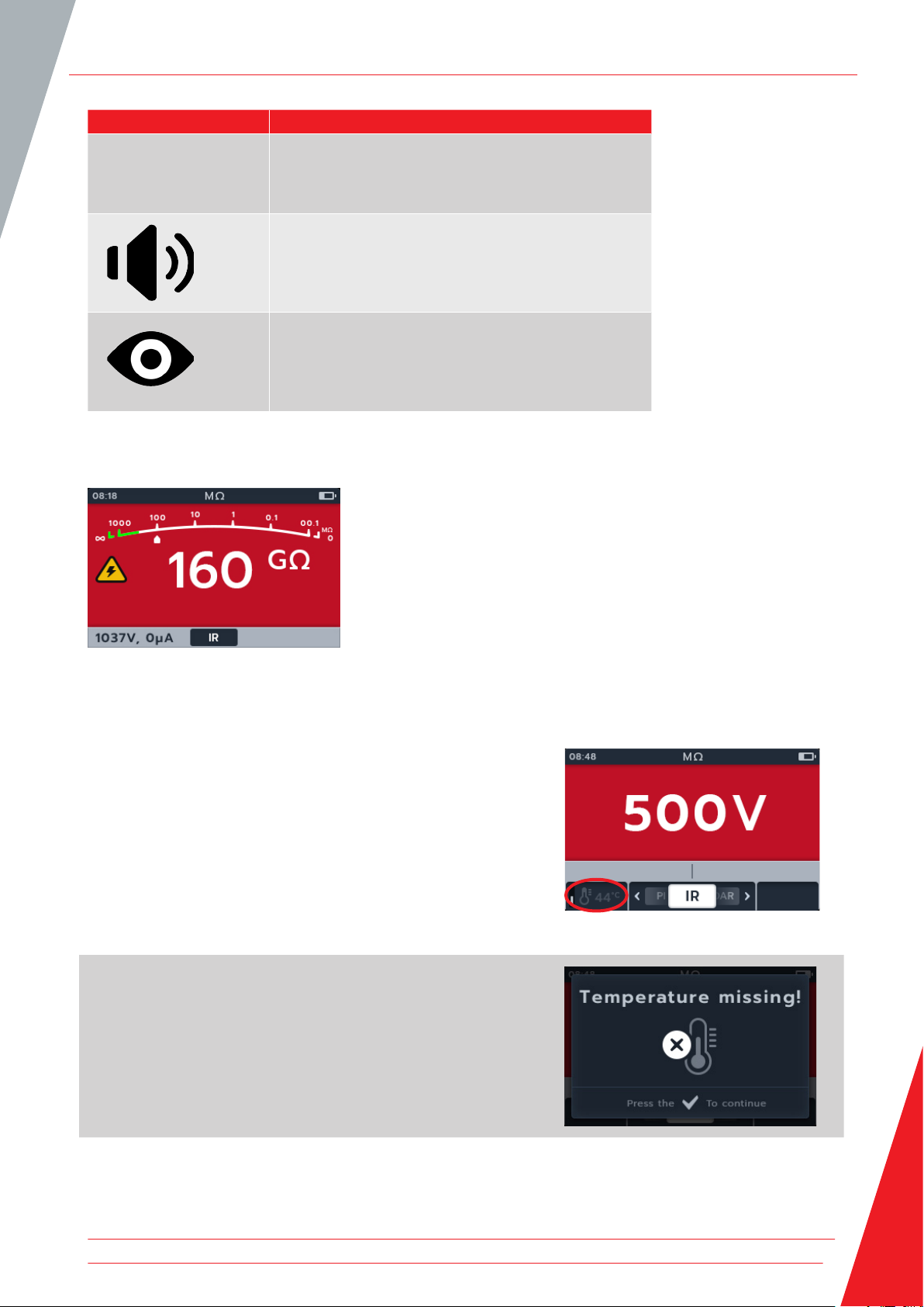
4.4.2 Temperature compensation
NOTE: Temperature compensation is only available in IR sub-mode. Temperature compensation is off by default.
Before an insulation resistance test can be carried out with
temperature compensation enabled, the temperature of the unit
under test must be established.
For this procedure Refer to 14.1.4 Temperature compensation on
page 72
If a temperature measurement hasn’t been made, the left of the
secondary field will show -- °C.
If a test is attempted the unit will display Temperature missing.
www.megger.com 17
Page 24

Insulation Resistance Tests
If the temperature reading is more than 30 minutes old, a red
time stamp will be displayed in the secondary field above the
temperature reading.
4.5 3 Phase (3P)
1. Connect the test leads to the MTR105.
1.1. Press the Information ( ) button to view the lead set
up diagram.
NOTE: when the diagram is displayed a test cannot be
performed. Press Information ( ) button to return to the test
screen.
2. Connect the test leads to the unit under test.
NOTE: The connection is for illustrative purposes only
When performing phase to phase measurements, the star or
delta configuration has to be disconnected.
3. Select the required insulation test voltage.
4. The display will show the selected voltage, in this case 500 V.
18 www.megger.com
Page 25
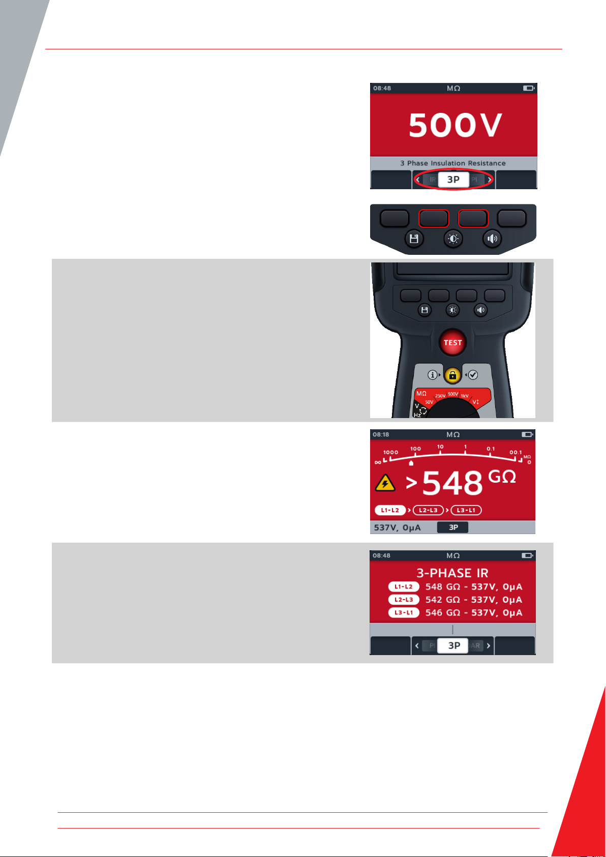
5. Press soft keys 2 and 3 to move the carousel left or right
through sub-modes to 3P (3 phase).
NOTE: The full title text of the sub-mode will appear in the
secondary field for a few seconds.
6. To start the test press the TEST button.
A warning triangle will flash on screen.
NOTE: The test can be stopped at any time by pressing the TEST
button.
Insulation Resistance Tests
7. During the tests:
The primary field displays the test results and the active
and completed phase to phase tests in the three phase
sequence.
The secondary field displays actual voltage output and the
current measured.
8. When the test has completed:
The primary field displays the test results and also the
actual voltage output and the current measured.
www.megger.com 19
Page 26

Insulation Resistance Tests
9. The result can be saved by pressing the SAVE button. A
message will inform you the data was saved and which asset
ID it was saved to.
NOTE If the test was stopped before completion, it cannot be
saved.
10. To restart the test press the TEST button again.
4.6 Polarization Index (PI)
1. Connect the test leads to the MTR105.
1.1. Press the Information ( ) button to view the lead set
up diagram.
NOTE: when the diagram is displayed a test cannot be
performed. Press Information ( ) button to return to the test
screen.
This test can also be performed with just the red and the black
lead.
2. Connect the test leads to the unit under test.
NOTE: The connection is for illustrative purposes only.
When performing phase to phase measurements, the star or
delta configuration has to be disconnected.
3. Select the required insulation test voltage.
20 www.megger.com
Page 27

4. The display will show the selected voltage, in this case 500 V.
5. Press soft keys 2 and 3 to move the carousel left or right
through sub-modes to PI (Polarization Index).
NOTE: The full title text of the sub-mode will appear in the
secondary field for a few seconds.
Insulation Resistance Tests
6. To start the test press the TEST button.
The test will start and the clock will appear in the bottom left of
the primary screen. The test will continue for 10 minutes. The
clock will countdown the test. An interval result will appear after
1 minute.
A warning triangle will flash on screen.
NOTE: The test can be stopped at any time by pressing the TEST
button.
7. During the tests,
The primary field displays the test results.
The secondary field displays actual voltage output and the
current measured.
8. When the test has completed,
The primary field displays the test results.
www.megger.com 21
Page 28

Insulation Resistance Tests
9. The result can be saved by pressing the SAVE button. A
message will inform you the data was saved and which asset
ID it was saved to.
NOTE If the test was stopped before completion, it cannot be
saved.
10. To restart the test pressing the TEST button again.
4.7 Timed (T(s)) Test
1. Connect the test leads to the MTR105.
1.1. Press the Information ( ) button to view the lead set
up diagram.
NOTE: When the diagram is displayed a test cannot be
performed. Press Information ( ) button to return to the test
screen.
This test can also be performed with just the red and the black
lead.
2. Connect the test leads to the unit under test.
NOTE: The connection is for illustrative purposes only
When performing phase to phase measurements, the star or
delta configuration has to be disconnected.
3. Select the required insulation test voltage.
22 www.megger.com
Page 29

4. The display will show the selected voltage, in this case 500 V.
5. Press soft keys 2 and 3 to move the carousel left or right
through sub-modes to T(s) (Timed Test).
NOTE: The full title text of the sub-mode will appear in the
secondary field for a few seconds.
Insulation Resistance Tests
6. To start the test press the TEST button.
The clock will appear in the bottom left corner of the primary
field. The Timed test is user configurable and can run for
1,2,3,4,5,6,7,8,9, or 10 minutes Refer to 14.1.6 Timed Insulation
on page 73
A warning triangle will flash on screen.
NOTE: The test can be stopped at any time by pressing the TEST
button.
7. During the tests,
The primary field displays the test results.
The secondary field displays actual voltage output and the
current measured.
8. When the test has completed,
The primary field displays the test results.
The secondary field displays actual voltage output and the
current measured.
www.megger.com 23
Page 30

Insulation Resistance Tests
9. The result can be saved by pressing the SAVE button.
A message will inform you the data was saved and which
asset ID it was saved to.
10. To restart the test pressing the TEST button again.
4.8 Dielectric Absorption Ratio (DAR)
1. Connect the test leads to the MTR105.
1.1. Press the Information ( ) button to view the lead set
up diagram.
NOTE: when the diagram is displayed a test cannot be
performed. Press Information ( ) button to return to the test
screen.
This test can also be performed with just the red and the black
lead.
2. Connect the test leads to the unit under test.
NOTE: The connection is for illustrative purposes only.
When performing phase to phase measurements, the star or
delta configuration has to be disconnected.
3. Select the required insulation test voltage.
24 www.megger.com
Page 31

4. The display will show the selected voltage, in this case 500 V.
5. Press soft keys 2 and 3 to move the carousel left or right
through sub-modes to DAR (Dielectric Absorption Ratio).
NOTE: The full title text of the sub-mode will appear in the
secondary field for a few seconds.
Insulation Resistance Tests
6. To start the test press the TEST button.
The clock will appear in the bottom left corner of the primary
field as the DAR test runs for one minute.
A warning triangle will flash on screen.
NOTE: The test can be stopped at any time by pressing the TEST
button.
7. During the tests,
The primary field displays the test results.
The secondary field displays actual voltage output and the
current measured.
8. When the test has completed,
The primary field displays the test results.
The secondary field displays actual voltage output and the
current measured.
www.megger.com 25
Page 32

Insulation Resistance Tests
9. The result can be saved by pressing the SAVE button. A
message will inform you the data was saved and which asset
ID it was saved to.
NOTE If the test was stopped before completion, it cannot be
saved.
10. To restart the test pressing the TEST button again.
4.9 Variable voltage
1. Set the voltage required under the variable voltage test
setting. Refer to 14.1.7 Variable Voltage on page 73
2. Connect the test leads to the MTR105.
2.1. Press the Information ( ) button to view the lead set
up diagram.
NOTE: when the diagram is displayed a test cannot be
performed. Press Information ( ) button to return to the test
screen.
This test can also be performed with just the red and the black
lead.
3. Connect the test leads to the unit under test.
NOTE: The connection is for illustrative purposes only
When performing phase to phase measurements, the star or
delta configuration has to be disconnected.
4. Turn rotary switch to select variable voltage position.
26 www.megger.com
Page 33

5. The display will show the selected voltage, in this case 10 V.
6. Press soft keys 2 and 3 to move the carousel left or right
through sub-modes. IR is default, scroll through to 3P, PI,
T(s) DAR.
Insulation Resistance Tests
7. Run the chosen test as described in the previous sections.
www.megger.com 27
Page 34

Voltmeter
5. Voltmeter
5.1 TRMS (True RMS)
Default is TRMS mode shows true RMS voltage. In TRMS mode the MTR105 will measure both ac and dc components
of the supply voltage (ac+dc).
1. Connect the test leads to the MTR105.
1.1. Press the Information ( ) button to view the lead set
up diagram.
NOTE: When the diagram is displayed a test cannot be
performed. Press Information ( ) button to return to the test
screen.
2. Turn rotary switch to select Voltmeter (V) position.
3. The TRMS test starts automatically.
4. During the tests,
The primary field displays the measured voltage.
The secondary field displays frequency.
5. The result can be saved by pressing the SAVE button. A
message will inform you the data was saved and which asset
ID it was saved to.
28 www.megger.com
Page 35

5.2 AC or DC
1. Connect the test leads to the MTR105.
1.1. Press the Information ( ) button to view the lead set
up diagram.
NOTE: When the diagram is displayed a test cannot be
performed. Press Information ( ) button to return to the test
screen.
2. Turn rotary switch to select Voltmeter (V) position.
Voltmeter
3. Press soft keys 2 and 3 to move the carousel left or right
through sub-modes to ac or dc as required.
NOTE: The full title text of the sub-mode will appear in the
secondary field for a few seconds.
4. The ac and dc tests start automatically.
5. During the ac tests,
The primary field displays the measured voltage.
The secondary field displays frequency.
6. During the dc tests,
The primary field displays the measured voltage.
www.megger.com 29
Page 36

Voltmeter
7. The result can be saved by pressing the SAVE button. A
message will inform you the data was saved and which asset
ID it was saved to.
5.3 Supply Phase Rotation
1. Connect the test leads to the MTR105.
1.1. Press the Information ( ) button to view the lead set
up diagram.
NOTE: when the diagram is displayed a test cannot be
performed. Press Information ( ) button to return to the test
screen
2. Turn rotary switch to select Voltmeter (V) position.
3. Press soft keys 2 and 3 to move the carousel left or right
through sub-modes to Supply Phase Rotation.
NOTE: The full title text of the sub-mode will appear in the
secondary field for a few seconds.
30 www.megger.com
Page 37

4. This test starts automatically.
NOTE: Phase rotation result requires all phases connected
before a result can be given.
5. During the tests,
The primary field displays the phase rotation sequence of
the supply and constantly updating results for each phase
sequence of the supply.
The secondary field displays frequency.
6. The result can be saved by pressing the SAVE button. A
message will inform you the data was saved and which asset
ID it was saved to.
Voltmeter
www.megger.com 31
Page 38

Continuity
6. Continuity
NOTE: Results of measurements can be adversely affected by impedances of additional operating circuits connected
in parallel or by transient current.
6.1 Uni-direction
1. Connect the test leads to the MTR105.
1.1. Press the Information ( ) button to view the lead set
up diagram.
NOTE: When the diagram is displayed a test cannot be
performed. Press Information ( ) button to return to the test
screen.
2. Turn rotary switch to select Continuity position.
3. If required, Turn the buzzer on, off or visual as required by
pressing buzzer button.
NOTE: This is only available in uni-direction mode.
4. To adjust the threshold press soft key 4.
NOTE: The buzzer mode bypasses the continuity detection and
voltage pretesting.
32 www.megger.com
Page 39

5. A new screen will open where the threshold can be adjusted
pressing soft keys 2 and 3.
6. Press soft key 4 to save and return to the original screen.
OR
Press soft key 1 to cancel and return to the original screen.
7. Press soft keys 2 and 3 to move the carousel left or right
through sub-modes to uni-direction
NOTE: The full title text of the sub-mode will appear in the
secondary field for a few seconds.
Continuity
8. The test current can be toggled between 200 mA and
20 mA pressing soft key 1.
9. NULL the test leads by touching the two test probe ends.
Press the TEST button until the NULL (symbol) appears on the
screen. The ohmic value on the primary screen will read 0 Ω.
10. Connect the test leads to the unit under test.
NOTE: The connection is for illustrative purposes only showing
winding resistance across phase 1.
www.megger.com 33
Page 40

Continuity
11. This test starts automatically when the test leads are
connected to the unit under test.
12. During the tests,
The primary field displays the result of the true resistance
of the unit under test.
The secondary field displays test current and the previous
resistance value in Uni direction.
6.2 Bi-direction
1. Connect the test leads to the MTR105.
1.1. Press the Information ( ) button to view the lead set
up diagram.
NOTE: When the diagram is displayed a test cannot be
performed. Press Information ( ) button to return to the test
screen.
2. Turn rotary switch to select Continuity position.
3. Press soft keys 2 and 3 to move the carousel left or right
through sub-modes to bi-direction
NOTE: The full title text of the sub-mode will appear in the
secondary field for a few seconds.
34 www.megger.com
Page 41

4. The test current can be toggled between 200 mA and
20 mA pressing soft key 1.
5. NULL the test leads by touching the two test probe ends.
Press the TEST button until the NULL (symbol) appears on the
screen. The ohmic value on the primary screen will read 0 Ω.
Continuity
6. Connect the test leads to the unit under test.
NOTE: The connection is for illustrative purposes only showing
winding resistance across phase 1.
7. This test starts automatically.
8. During the tests,
The primary field displays the result of the true resistance
of the unit under test
The secondary field displays the test current and the
resistance values in both directions - highest value shown
in Primary.
The test in bi-direction mode runs continually
www.megger.com 35
Page 42

Continuity
6.3 Diode test
1. Connect the test leads to the MTR105.
1.1. Press the Information ( ) button to view the lead set
up diagram.
NOTE: When the diagram is displayed a test cannot be
performed. Press Information ( ) button to return to the test
screen.
2. Turn rotary switch to select Continuity position.
3. Press soft keys 2 and 3 to move the carousel left or right
through sub-modes to Diode test.
NOTE: The full title text of the sub-mode will appear in the
secondary field for a few seconds.
4. This test starts automatically.
5. During the tests, the primary field displays the voltage drop
as it is measured.
A good forward-biased diode displays a voltage drop ranging from 0.5 to 0.8 V for the most commonly used
silicon diodes. Some germanium diodes have a voltage drop ranging from 0.2 to 0.3 V. The voltage drop is also
dependent on the test current.
The meter displays O/C when a good diode is reverse-biased. The O/C reading indicates the diode is functioning
as an open switch.
A bad (open circuit) diode does not allow current to flow in either direction. The meter will display O/C in both
directions when the diode is opened.
A short circuited diode has zero voltage drop reading in both directions.
36 www.megger.com
Page 43

Continuity
If a voltage between 0 V and 3 V is detected, the buzzer will sound and background flash /or background flash
depending on what buzzer mode is activated.
If a voltage above 3 V is detected, the buzzer will NOT sound and the background will not flash, the display will
show “OL”.
NOTE: The user is responsible for connecting test probes across the diode under test. There is no information
displayed in the secondary field at this point. The only information to display is the diode drop voltage if the
instrument senses a voltage across the device. If no current flows the main display will show “O/C”.
www.megger.com 37
Page 44

DLRO Digital Low Resistance Ohmmeter
7. DLRO Digital Low Resistance Ohmmeter
7.1 Manual single direction test
1. Connect the test leads to the MTR105.
1.1. Press the Information ( ) button to view the lead set
up diagram.
NOTE: When the diagram is displayed a test cannot be
performed. Press Information ( ) button to return to the test
screen.
2. Connect the test leads to the unit under test.
NOTE: The connection is for illustrative purposes only showing
winding resistance across phase 1.
3. Turn rotary switch to select the DLRO (mΩ) position.
4. Press soft keys 3 to choose the sub-mode uni-directional.
NOTE: The full title text of the sub-mode will appear in the
secondary field for a few seconds.
38 www.megger.com
Page 45

5. If there is a continuity reading detected for C and P
connections the secondary fields will display with a tick and
background will be green.
6. To start the test press the TEST button.
7. The test runs for a few seconds, then automatically stops.
DLRO Digital Low Resistance Ohmmeter
8. During the tests,
The primary field displays the result with the actual
current being delivered. As the resistance gets higher the
current will get lower.
The secondary field displays the continuity on the Current
(C1-C2) and potential (P1-P2) circuits.
9. The result can be saved by pressing the SAVE button. A
message will inform you the data was saved and which asset
ID it was saved to.
10. To restart the test, press the TEST button again.
www.megger.com 39
Page 46

DLRO Digital Low Resistance Ohmmeter
7.2 Auto Single direction test
1. Connect the test leads to the MTR105.
1.1. Press the Information ( ) button to view the lead set
up diagram.
NOTE: When the diagram is displayed a test cannot be
performed. Press Information ( ) button to return to the test
screen.
2. Connect the test leads to the unit under test.
NOTE: The connection is for illustrative purposes only showing
winding resistance across phase 1.
3. Turn rotary switch to select the DLRO (mΩ) position.
4. Press soft keys 3 to choose the sub-mode uni-directional
NOTE: The full title text of the sub-mode will appear in the
secondary field for a few seconds.
40 www.megger.com
Page 47

5. Press soft key 1 to enable auto mode.
6. If there is a continuity reading detected for C and P
connections the secondary fields will display with a tick and
background will be green.
If all the leads are connected correctly, test will start immediately.
7. The test runs for a few seconds then automatically stop
8. During the tests,
The primary field displays the result with the actual
current being delivered. As the resistance gets higher the
current will get lower.
The secondary field displays the continuity on the Current
(C1-C2) and potential (P1-P2) circuits.
DLRO Digital Low Resistance Ohmmeter
9. The result can be saved by pressing the SAVE button. A
message will inform you the data was saved and which asset
ID it was saved to.
10. To restart the test, re-connect to a new test piece and the
test will start automatically.
7.3 Manual bi-direction test
1. Connect the test leads to the MTR105.
1.1. Press the Information ( ) button to view the lead set
up diagram.
NOTE: When the diagram is displayed a test cannot be
performed. Press Information ( ) button to return to the test
screen.
www.megger.com 41
Page 48

DLRO Digital Low Resistance Ohmmeter
2. Connect the test leads to the unit under test.
NOTE: The connection is for illustrative purposes only showing
winding resistance across phase 1.
3. Turn rotary switch to select the DLRO (mΩ) position.
4. Press soft keys 2 to choose the sub-mode bi-directional.
NOTE: The full title text of the sub-mode will appear in the
secondary field for a few seconds.
5. If there is a continuity reading detected for C and P
connections the secondary fields will display with a tick and
background will be green.
42 www.megger.com
Page 49

6. To start the test press the TEST button.
7. The test runs for a few seconds, then automatically stop.
8. During the tests,
The primary field displays a rotating circle to show a test
is underway.
The secondary field displays the continuity on the Current
(C1-C2) and potential (P1-P2) circuits.
DLRO Digital Low Resistance Ohmmeter
9. When the test has completed,
The primary field displays the result for current and
resistance in each direction and an average of the two.
The secondary field displays the continuity on the Current
(C1-C2) and potential (P1-P2) circuits.
10. The result can be saved by pressing the SAVE button. A
message will inform you the data was saved and which asset
ID it was saved to.
11. To restart the test, press the TEST button again.
www.megger.com 43
Page 50

DLRO Digital Low Resistance Ohmmeter
7.4 Auto Bi direction test
1. Connect the test leads to the MTR105.
1.1. Press the Information ( ) button to view the lead set
up diagram.
NOTE: When the diagram is displayed a test cannot be
performed. Press Information ( ) button to return to the test
screen.
2. Connect the test leads to the unit under test.
NOTE: The connection is for illustrative purposes only showing
winding resistance across phase 1.
3. Turn rotary switch to select the DLRO ( mΩ ) position.
4. Press soft keys 2 to choose the sub-mode bi-directional.
NOTE: The full title text of the sub-mode will appear in the
secondary field for a few seconds.
44 www.megger.com
Page 51

5. Press soft key 1 to enable auto mode.
6. If there is a continuity reading detected for C and P
connections the secondary fields will display with a tick and
background will be green.
7. If all the leads are connected correctly, test will start
immediately, runs for a few seconds and then automatically
stop.
8. During the tests,
The primary field displays a rotating circle to show a test
is underway
The secondary field displays the continuity on the Current
(C1-C2) and potential (P1-P2) circuits
DLRO Digital Low Resistance Ohmmeter
9. When the test has completed,
The primary field displays the result for current and
resistance in each direction and an average of the two.
The secondary field displays the continuity on the Current
(C1-C2) and potential (P1-P2) circuits.
10. The result can be saved by pressing the SAVE button. A
message will inform you the data was saved and which asset
ID it was saved to.
11. To restart the test, re-connect to a new test piece and the
test will start automatically.
www.megger.com 45
Page 52

DLRO Digital Low Resistance Ohmmeter
7.5 Test failure
7.5.1 Lost connection
Should the connection be lost during the test the MTR105 will
notify the user. The user can re-make the connection then
restart the test after a few seconds by pressing the test button or
by reconnecting to a test piece.
46 www.megger.com
Page 53

8. Direction of Motor Rotation
1. Connect the test leads to the MTR105.
1.1. Press the Information ( ) button to view the lead set
up diagram.
Connect L1 to phase 1
Connect L2 to phase 2
Connect L3 to phase 3
Please ensure the motor is configured for star (Y) or delta
configuration before performing the test.
NOTE: when the diagram is displayed a test cannot be
performed. Press Information ( ) button to return to the test
screen.
2. Connect the test leads to the unit under test.
NOTE: The connection is for illustrative purposes only.
Direction of Motor Rotation
3. Turn rotary switch to select direction of motor rotation
position.
4. Rotate the motor in one direction. Check if display matches
L1 L2 L3 correct phases of rotation.
5. Rotate the motor in opposite direction. Check if display
matches L3 L2 L1 correct phases of rotation
www.megger.com 47
Page 54

Inductance (L); Capacitance (C); Resistance (R) (LCR)
9. Inductance (L); Capacitance (C); Resistance (R) (LCR)
NOTE: Results of measurements can be adversely affected by impedances of additional operating circuits connected
in parallel or by transient current.
9.1 Auto
1. Connect the test leads to the MTR105.
1.1. Press the Information ( ) button to view the lead set
up diagram.
NOTE: When the diagram is displayed a test cannot be
performed. Press Information ( ) button to return to the test
screen.
2. Connect the test leads to the unit under test.
NOTE: The connection is for illustrative purposes only showing
connection across phase 1.
3. Turn rotary switch to select the LCR position.
4. Press soft keys 2 and 3 to move the carousel left or right
through sub-modes to auto capacitance / inductance test.
NOTE: The full title text of the sub-mode will appear in the
secondary field for a few seconds.
48 www.megger.com
Page 55

Inductance (L); Capacitance (C); Resistance (R) (LCR)
5. Press soft keys 1 to toggle between 120 Hz and 1000 Hz.
6. To start the test press the TEST button.
The MTR105 determines if the load is inductive, capacitive or
resistive automatically.
7. During the tests,
The primary field displays the result for the reactive
component. (This could be capacitance, inductance or
resistance).
The secondary field displays the frequency.
9.2 Capacitance or inductance
1. Connect the test leads to the MTR105.
1.1. Press the Information ( ) button to view the lead set
up diagram.
NOTE: When the diagram is displayed a test cannot be
performed. Press Information ( ) button to return to the test
screen.
www.megger.com 49
Page 56

Inductance (L); Capacitance (C); Resistance (R) (LCR)
2. Connect the test leads to the unit under test.
NOTE: The connection is for illustrative purposes only showing
connections across phase 1.
3. Turn rotary switch to select the LCR position.
4. Press soft keys 2 and 3 to move the carousel left or right
through sub-modes to capacitance or inductance test.
NOTE: The full title text of the sub-mode will appear in the
secondary field for a few seconds.
( ) capacitance
( ) inductance
5. Press soft keys 1 to toggle between 120 Hz and 1000 Hz.
50 www.megger.com
Page 57

Inductance (L); Capacitance (C); Resistance (R) (LCR)
6. To start the test press the TEST button.
The MTR105 determines if the load is inductive, capacitive or
resistive automatically.
7. During the tests,
The primary field displays a rotating circle to show a test
is underway.
The secondary field displays the frequency.
8. During the tests,
The primary field displays the result for the reactive
component. (This could be capacitance, inductance or
resistance).
The secondary field displays the frequency.
9.3 LCR Calibration
NOTE For full MTR105 re-calibration procedure refer to Refer to 18. Calibration, Repair and Warranty on page 84.
1. Inductance calibration can be accessed from any sub-mode
within the LCR family by pressing soft key 4.
www.megger.com 51
Page 58

Inductance (L); Capacitance (C); Resistance (R) (LCR)
2. The open circuit calibration screen appears.
3. With the leads connected to the instrument but the circuit
kept open (separated).
4. Press soft key 4 to begin calibration.
5. Calibration will run for about 14 seconds (progress animation
will show).
6. After calibration the confirmation screen will appear.
7. Continue by pressing the tick button ( ) or Soft key 4.
8. The closed circuit calibration screen appears.
9. With the leads connected to the instrument, close the circuit
(short circuit)
10. Press soft key 4 to begin calibration.
11. Calibration will run for about 14 seconds (progress animation
will show).
12. After calibration the confirmation screen will appear.
13. Press the tick button ( ) or soft key 4 to return to the last
LCR test mode.
The MTR105 has been successfully recalibrated and is ready for
use. The new calibration will be stored.
52 www.megger.com
Page 59

14. If calibration fails, 2 options appear:
Press soft key 1 to go back
or
Press the tick button ( ) or soft key 4 to try again
Inductance (L); Capacitance (C); Resistance (R) (LCR)
www.megger.com 53
Page 60

Temperature measurement
10. Temperature measurement
Thermocouple connected, type “T” is set as default, the MTR105 can also be configured for “J” and “K” type
thermocouples.
Before an insulation resistance test can be carried out with temperature compensation enabled a temperature
measurement must be carried out to establish the temperature of the unit under test.
1. Temperature measurement screen will display O/C when the
thermocouple is not detected and there is not a previous
temperature measurement reordered.
2. Two options are displayed:
2.1. Connect the thermocouple for an accurate temperature
measurement.
2.2. Press soft key 4 for a manual temperature
measurement.
10.1 Thermocouple temperature measurement
1. Connect the thermocouple test leads to the MTR105.
1.1. Press the Information ( ) button to view the lead set
up diagram.
NOTE: When the diagram is displayed a test cannot be
performed. Press Information ( ) button to return to the test
screen.
NOTE: The thermocouples are sensitive to polarity.
2. Turn rotary switch to select the Thermometer position.
54 www.megger.com
Page 61

3. Press soft keys 2 and 3 to move the carousel left or right to
choose thermocouple type T, K or J.
A thermocouple symbol appears in the bottom left of the
primary screen, alongside the type of thermocouple selected.
4. Press soft key 1 to toggle between ºC (Centigrade) or ºF
(Fahrenheit).
Temperature measurement
5. Place the thermocouple against the test piece and allow the
thermocouple to rise to a stable temperature.
6. The unit starts measuring the temperature as soon as it
detects the probe is connected.
7. During the test the primary field displays the measured
temperature.
NOTE : If the thermocouple is not connected or is damaged the
primary field will display “O/C”
www.megger.com 55
Page 62

Temperature measurement
8. The result can be saved by pressing the SAVE button. A
message will inform you the data was saved and which asset
ID it was saved to.
10.2 Manual Temperature measurement
1. Turn rotary switch to select the Thermometer position.
2. Press soft key 4.
56 www.megger.com
Page 63

3. Press soft keys 2 and 3 to select a positive or negative
temperature.
4. Press soft key 4 to confirm.
or
Soft key 1 to cancel.
5. Press soft key 2 and 3 to scroll through the digits.
6. Press soft key 4 to accept the first digit and move to the
next.
7. Press soft key 2 and 3 to scroll through the digits.
8. Press soft key 4 to accept the second digit and move to the
next.
Temperature measurement
9. Press soft key 2 and 3 to scroll through the digits.
10. Press soft key 4 to accept the third digit and move to the
next.
11. Press soft key 2 and 3 to scroll through the digits.
12. Press soft key 4 to accept the temperature value.
13. Press soft key 1 to cancel and return to the previous menu at
any point.
14. The new temperature will be displayed.
The result can be saved by pressing the SAVE button. A
message will inform you the data was saved and which asset
ID it was saved to.
www.megger.com 57
Page 64

Data management
11. Data management
Use data management mode to view saved test results and transfer saved test results to USB drive or PC.
11.1 Creating a new asset ID
1. Turn rotary switch to select the data management position.
The primary field shows list of Assets stored on the MTR.
The secondary field shows the amount of entries, the total
storage available are shown in the left hand field and the
number of entries under the selected asset are shown in the
right hand field.
2. Press soft keys 2 and 3 to scroll up and down through the
asset list.
3. Press soft key 1 to type in a new asset. The relevant
language keyboard screen will appear.
58 www.megger.com
Page 65

4. Press soft keys 1, 2, 3 and 4 to navigate the keyboard
5. Press the tick button ( ) to type the selected character into
the title space in secondary field.
Upper case can be selected via the shift key.
Select the 123 key for numbers and other symbols.
6. Press the save button to create the asset.
or
To cancel the entry select key and press the tick button ( ).
11.2 Using an existing asset ID
1. Turn rotary switch to select the data management position.
The primary field shows list of assets stored on the MTR.
Data management
The secondary field shows the amount of entries, the total
storage available are shown in the left hand field and the
number of entries under the selected asset are shown in the
right hand field.
2. Press soft keys 2 and 3 to scroll up and down through the
asset list
www.megger.com 59
Page 66

Data management
3. Press the SAVE button to assign the next measurements to
this asset.
11.3 Deleting an asset
1. Turn rotary switch to select the data management position.
The primary field shows list of Assets stored on the MTR.
The secondary field shows the amount of entries, the total
storage available are shown in the left hand field and the
number of entries under the selected asset are shown in the
right hand field.
2. Press soft keys 2 and 3 to scroll up and down through the
asset list.
60 www.megger.com
Page 67

3. Press soft key 4 to delete chosen asset and all its entries.
4. Press soft key 4 to confirm
or
Soft key 1 to cancel.
Data management
11.4 Deleting items from within an asset
1. Turn rotary switch to select the data management position.
The primary field shows list of Assets stored on the MTR
The secondary field shows the amount of entries, the total
storage available are shown in the left hand field and the
number of entries under the selected asset are shown in the
right hand field.
www.megger.com 61
Page 68

Data management
2. Press soft keys 2 and 3 to scroll up and down through the
asset list.
3. Press the tick button ( ) to open the chosen asset and all
its entries.
4. Press soft keys 2 and 3 to scroll up and down through the
list.
5. Press soft key 4 to delete chosen date and all its entries.
6. Press soft key 4 to confirm
or
Soft key 1 to cancel.
62 www.megger.com
Page 69

11.5 Deleting a single test
1. Turn rotary switch to select the data management position.
The primary field shows list of assets stored on the MTR
The secondary field shows the amount of entries, the total
storage available are shown in the left hand field and the
number of entries under the selected asset are shown in the
right hand field.
2. Press soft keys 2 and 3 to scroll up and down through the
asset list.
Data management
3. Press the tick button ( ) to open the chosen asset and all
its entries.
www.megger.com 63
Page 70

Data management
4. Press soft keys 2 and 3 to scroll up and down through the
list.
5. Press the tick button ( ) to open the chosen date and all its
entries.
The date opens out into colour - coded text (these are the same
colours in use on the MTR105 rotary switch).
A number, in parenthesis, to the right hand side of the text line
shows the number of results of that type of test saved to that
asset, on that date. If no number is present, there are no results
saved against this test type.
6. Press soft keys 2 and 3 to scroll up and down through the
list.
7. Press the tick button ( ) to open to select the test type
required.
64 www.megger.com
Page 71

8. Press soft keys 2 and 3 to scroll up and down through the
list.
9. Press soft key 4 to delete the entry.
10. Press soft key 4 to confirm
or
Soft key 1 to cancel.
Data management
11.6 Exporting entries to USB
1. Turn rotary switch to select the data management position.
The primary field shows list of assets stored on the MTR.
The secondary field shows the amount of entries and the total
storage available are shown in the left hand field and the
number of entries under the selected asset are shown in the
right hand field.
2. Connect a USB Memory stick to the MTR.
A USB type A socket is provided on the top of the MTR105 for
transferring test results. The position is clearly marked with a USB
symbol, the slider must be in the backward position.
NOTE: When a USB memory stick is inserted, the icon for soft
key 1 will change from a plus ( ) to the
download symbol ( ).
www.megger.com 65
Page 72

Data management
3. Use soft keys 2 and 3 to scroll up and down through the
asset list.
4. Press soft key 1 to begin upload.
5. Press soft key 2 to upload the single selected measurement
or
Press soft key 3 to upload all saved measurements
or
Press soft key 1 to cancel.
6. If matching names already exist in the storage device the
user is asked if the MTR105 should overwrite them.
66 www.megger.com
Page 73

7. As the data is uploading, a message appears and blocks
navigation in the secondary field. No other work can be
carried out while uploading is in progress.
8. When the export is successful the MTR105 will notify the
user.
Data management
www.megger.com 67
Page 74

Firmware update
12. Firmware update
Connect a USB flash drive to the MTR105 with the firmware
update file in the root directory. The MTR105 will automatically
update when the instrument is turned on if a firmware update is
available.
1. Plug the USB pen drive in to the USB slot at the top of the
instrument.
2. The boot loader screen will be displayed when the
instrument starts up.
3. Press [OK] to upgrade firmware or [TEST] to cancel.
4. The will progress through various stages.
5. When complete, remove the USB.
6. Restart the MTR (turn off and on).
68 www.megger.com
Page 75

7. The firmware update screen will display while the update in
progress.
8. The instrument will reboot after the update is complete.
Firmware update
www.megger.com 69
Page 76

Error and Warning Conditions
13. Error and Warning Conditions
If an error code appears on the display follow the on screen instructions.
13.1 Failed export
1. If the export fails, the MTR105 will notify the user. This
may be because the receiving USB device is faulty, is
disconnected, full or in some other way fails.
2. The MTR will return to its previous screen.
13.2 Fuse Failure
If a fuse fails, no measurements can be carried out. A message
will appear each time the user tries to run a test. Close the
message by pressing tick button ( ). Refer to 15.4 Battery and
Fuse Replacement on page 78
13.3 Battery Low
The battery is too low to perform a test.
If the error code number is 1000 or higher the instruction on screen will suggest rebooting the instrument and if the
problem persists, contact Megger.
For Megger contact details Refer to 18. Calibration, Repair and Warranty on page 84.
70 www.megger.com
Page 77

14. Settings
Various user settings can be adjusted, serial and software version numbers can be accessed in this section.
IR Test Settings General Settings Language settings
DAR Back-light timer English
Insulation threshold Battery Technology French
Lock Date Dutch
Temperature Compensation Instrument information Spanish
Terminal Lock out Voltage Key Press Notification
Time Insulation Sleep timer
Variable Voltage Time
Restore Factory settings
Rotate the switch to the settings position. The set up procedures are all similar to one-another. The following
paragraphs give details of some of the set up procedures, the information given will cover all of the settings
procedures.
14.1 IR Test Settings
Settings
IR settings are available as listed in the chart above.
1. Scroll through the individual settings using soft keys 2 and 3.
2. Use the tick button ( ) to select a setting.
2.1. This will toggle between the two options where a
toggle key is displayed to the right hand side.
or
2.1. This will enter a sub menu if more than two options are
available.
14.1.1 DAR Settings
There are two options available for DAR. Press the tick button ( ) to toggle between 15 seconds and 30 seconds.
www.megger.com 71
Page 78

Settings
14.1.2 Insulation threshold
There are a number options available for Insulation threshold.
1. Select Insulation Threshold, press the tick button ( ).
2. Press soft key 2 and 3 to scroll through the options.
3. Press soft key 4 to accept the selected setting.
4. Press soft key 1 to cancel and return to the previous menu.
14.1.3 Lock
The lock setting enables the lock button for IR tests.
There are two options available for Lock. Press the tick button ( ) to toggle between on and off.
14.1.4 Temperature compensation
1. Select temperature compensation press the tick button ( ).
2. Press soft key 2 and 3 to scroll through the options.
3. Press soft key 4 to accept the selected temperature setting
and move to the motor class setting.
4. Press soft key 2 and 3 to scroll through the options.
5. Press soft key 4 to accept the motor class setting.
6. Press soft key 1 to cancel and return to the previous menu.
14.1.5 Terminal lock out
1. Select Terminal lockout press the tick button ( ).
2. Press soft key 2 and 3 to scroll through the options.
3. Press soft key 4 to accept the selected setting.
4. Press soft key 1 to cancel and return to the previous menu.
72 www.megger.com
Page 79

14.1.6 Timed Insulation
1. Select Timed insulation press the tick button ( ).
2. Press soft key 2 and 3 to scroll through the options.
3. Press soft key 4 to accept the selected setting.
4. Press soft key 1 to cancel and return to the previous menu.
14.1.7 Variable Voltage
1. Select Variable voltage press the tick button ( ).
2. Press soft key 2 and 3 to scroll through the digits.
3. Press soft key 4 to accept the first digit and move to the
next.
4. Press soft key 2 and 3 to scroll through the digits.
Settings
5. Press soft key 4 to accept the second digit and move to the
next.
6. Press soft key 2 and 3 to scroll through the digits.
7. Press soft key 4 to accept the third digit and save the setting.
8. Press soft key 1 to cancel and return to the previous menu at
any point.
14.2 General Settings
14.2.1 Back-light timer
1. Select Back-light timer press the tick button ( ).
2. Press soft key 2 and 3 to scroll through the options.
3. Press soft key 4 to accept the selected setting.
4. Press soft key 1 to cancel and return to the previous menu.
14.2.2 Battery Technology
1. Select Battery technology press the tick button ( ).
2. Press soft key 2 and 3 to scroll through the options.
3. Press soft key 4 to accept the selected setting.
4. Press soft key 1 to cancel and return to the previous menu.
www.megger.com 73
Page 80

Settings
14.2.3 Date
1. Select Date press the tick button ( ).
2. Press soft key 2 and 3 to scroll through the date format.
3. Press soft key 4 to accept the format and move to the day.
4. Press soft key 2 and 3 to scroll through the day.
5. Press soft key 4 to accept the day and move to the month.
6. Press soft key 2 and 3 to scroll through the months.
7. Press soft key 4 to accept the month and move to the year.
8. Press soft key 2 and 3 to scroll through the year.
9. Press soft key 4 to accept and save the date.
10. Press soft key 1 to cancel and return to the previous menu at
any point.
14.2.4 Instrument information
1. Select instrument information press the tick button ( ).
2. The instrument information will display.
3. Press soft key 1 to return to the previous menu.
14.2.5 Key Press Notification
There are two options available for Key Press Notification. Press the tick button ( ) to toggle between ON and OFF.
14.2.6 Sleep timer
1. Select Sleep timer press the tick button ( ).
2. Press soft key 2 and 3 to scroll through the options.
3. Press soft key 4 to accept the selected setting.
4. Press soft key 1 to cancel and return to the previous menu.
74 www.megger.com
Page 81

14.2.7 Time
1. Select Time press the tick button ( ).
2. Press soft key 2 and 3 to scroll through the date format.
3. Press soft key 4 to accept the format and move to the hour.
4. Press soft key 2 and 3 to scroll through the hour.
5. Press soft key 4 to accept the hour and move to the minute.
6. Press soft key 2 and 3 to scroll through the minute.
7. Press soft key 4 to accept and save the time.
8. Press soft key 1 to cancel and return to the previous menu at
any point.
14.2.8 Restore factory settings
When the restore factory settings option is selected a pop screen
will appear.
1. Press and hold the tick button ( ) to store the factory
settings.
Settings
2. Press soft key 1 to cancel and return to the previous menu.
14.3 Language settings
The languages set in the MTR105 are English, French, German and Spanish.
From the settings menu screen select the Language sub-menu using soft keys 2 and 3.
Select the required language using soft keys 2 and 3, the language changes immediately.
www.megger.com 75
Page 82

Maintenance
15. Maintenance
15.1 General Maintenance
Test leads should be checked before use for damage and continuity.
Ensure the unit is kept clean and dry after use.
Close all covers when not in use.
15.2 Cleaning
1. Disconnect from mains power.
2. Wipe the instrument with a clean cloth dampened with either water or isopropyl alcohol (IPA).
15.3 Battery
Warning: Always set the instrument to Off and remove test leads before battery cells are removed or
installed.
Caution: Old batteries must be disposed of in accordance with local regulations.
Caution: Only use approved batteries as defined below.
Replacement battery types are: 6 x LR6 1.5 V Alkaline (AA), IEC HR6 1.2V NiMH or IEC FR6 1.5 V Lithium (LiFeS2),
Refer to 16. Specifications on page 80.
Battery technology (battery type) can be selected between alkaline, NiMH or Lithium. When changing between
battery types always ensure the correct type is selected in the settings menu, if this isn’t done the battery reading will
be incorrect.
To help maintain the health, reliability and longevity of the installed battery:
Ensure if using rechargeable batteries they are fully charged before use.
Store batteries in a cool, dry place. Battery cells can be damaged when exposed to heat.
15.3.1 Battery status
Warning: Do not recharge Alkaline or Lithium battery cells.
The battery condition icon is positioned at the top right hand corner of display. This icon is displayed at all times
when the MTR105 is switched on. When running on battery, the icon will indicate state of charge, the icon will be
filled in proportion to the state of charge.
When the battery is in a good state of charge the battery icon will be white and in a low state of charge the battery
icon will flash.
When the battery is very low a large red battery icon will appear in the primary field with the message “Battery
low please charge or replace to continue”. No tests will be able to be performed but changes to settings and
data handling can be carried out. The battery must be replaced (Alkaline/Lithium) or recharged (NiMH) before the
MTR105 can be used.
When the battery is charging, it will show an animation of the battery from empty to full, then repeats. Once the
battery is full, the animation stops.
The maximum charging time for NiMH batteries is 6 hours, normal charging time is approximately 4 hours.
76 www.megger.com
Page 83

Maintenance
15.3.2 12 V supply
When charging NiMH rechargeable battery cells, only use the power supply provided by Megger as an optional extra.
Other power supplies will not function with the MTR105. The Megger power supply is designed to preserve the
functions and accuracy of the MTR105.
15.3.3 Battery Charging
Warning: ONLY NiHM battery cells are rechargeable.
When charging the MTR while the instrument is OFF, an animated battery will display across the screen to show
charging is taking place. Once the battery is fully charged the screen will display a solid green battery.
Battery charging Battery fully charged
When charging the MTR while the instrument is OFF, an animated battery will display in the top right hand corner
of the screen. While the MTR is charging a test can not be performed. If the test button in pressed the buzzer will
sound. However the Data Management and Settings are fully accessible while the instrument is charging.
15.3.4 Battery error screens
Battery Low
The battery is too low to perform a test.
Charging Fault
A generic charging fault warning screen.
Turn off and disconnect the charger. Then reconnect and try
again.
www.megger.com 77
Page 84

Maintenance
Battery not chargeable
The battery settings are not correct to allow battery charging.
1. Check the correct battery type is in the instrument, Refer to
15.4 Battery and Fuse Replacement on page 78
2. Check the battery settings are NiHM, Refer to 14.2.2 Battery
Technology on page 73
15.4 Battery and Fuse Replacement
Warning: Remove all test leads before removing either the fuse or battery covers.
Caution: Battery cells should not be left in the instrument if remaining unused for an extended period.
5
6
1
2
4
3
No. Description Quantity
1 Screw, Captive 1
2 Cover, Battery 1
3 Battery isolation tab 1
4 Battery 6
5 Screw, Captive 1
6 Cover, Fuses 1
7 Fuses 2
7
78 www.megger.com
Page 85

Maintenance
15.4.1 Replace battery cells and remove isolation tab
The battery cells are housed in the lower section of the MTR105, behind the rotary switch. Looking at the back of
the instrument, the lower (battery) cover incorporates a stand and has the replacement cell types written on it.
NOTE: When replacing the battery cells, there is an approximate 3 minute window in which the MTR105 will retain
the settings for date and time. If left longer these settings will have to be re-made. If using the MTR105 for the first
time remove and discard the battery isolation tab (3).
1. Remove the test leads and ensure the MTR105 is switched off.
2. Slacken one captive cross-point screw (1) which is centred at the top of the cover.
3. Battery cover (2) will now lift away from the top.
4. Ease out of lugs at the bottom of the cover.
5. The six battery cells (4) can now be lifted out of the compartment.
Caution: Ensure the new cells are replaced in the correct polarity as indicated on the cells and battery
compartment.
Caution: Ensure all battery cells are of the same type, do not mix Alkaline, NiMH and Lithium.
6. Replace all six battery cells (4).
7. Replace the battery cover (2) in reverse order to above.
8. Re-secure with screw (1).
15.4.2 To replace the fuses
Caution: Glass fuses must not be used.
The fuses are housed in the upper section of the MTR105, behind the display. Looking at the back of the instrument,
the upper cover has a fuse symbol on it.
1. Remove the test leads and ensure the MTR105 is switched off.
2. Slacken one captive cross-point screw (5) from the left hand side of the top cover (marked fuses).
3. Fuse cover (6) will now lift away from the left hand side.
4. Ease out of lugs at right hand of the fuse cover.
5. The two fuses (7) can now be accessed and removed.
Caution: Ensure correct replacement fuses are used, 500 mA (FF) H. B. C. 30 kA minutes 1000 V (32 mm x 6
mm) refer to Refer to 16. Specifications on page 80.
6. Replace fuses (7) as required.
7. Replace the fuse cover (6) in reverse order to above.
8. Re-secure with captive screw (5).
NOTE: Fuses on the P terminals are not user replaceable. If these fail the instrument must be returned to Megger
for repair.
www.megger.com 79
Page 86

Specifications
16. Specifications
Specification Detail
Insulation resistance
Accuracy Volts Accuracy
50 V 10 GΩ ±2% ±2 digits ±4.0% per GΩ
100 V 20 GΩ ±2% ±2 digits ±2.0% per GΩ
250 V 50 GΩ ±2% ±2 digits ±0.8% per GΩ
500 V 100 GΩ ±2% ±2 digits ±0.4% per GΩ
1000 V 200 GΩ ±2% ±2 digits ±0.2% per GΩ
Operational Uncertainty: IEC61557-2
Polarisation index (PI): 10 minute / 1 minute ratio
Dielectric absorption ratio (DAR): User configurable 15 s or 30 s t1 start time with t2 fixed at 60 s
Guard terminal performance <5% error at 500 kΩ parallel circuit resistance with 100 MΩ load
Resolution 0.1 kΩ
Short circuit / charge current 2 mA +0% -50% (IEC61557-2)
Terminal voltage accuracy -0% +2% ±2 V
Test current 1 mA at min. pass value of insulation to a max. of 2 mA max
Operation range 0.10 MΩ to 1.0 GΩ (IEC61557-2)
Leakage current display 0.1 µA resolution 10% (±3 digits)
Voltage display ±3% ±2 digits ±0.5% of rated voltage
NOTE: Above specifications only apply when high quality silicone leads are being used - as supplied with the
instrument.
Continuity
Measurement 0.01 Ω to 1 MΩ (0 to 1000 kΩ analogue scale)
Accuracy ±3 % ±2 digits (0 to 99.9 Ω ) ±5% ± 2 digits (100 Ω - 500 kΩ)
Service Error: IEC61557-4
Test current 200 mA (–0 mA +20 mA) (0.01 Ω - 4 Ω)
Polarity Single polarity (Default) Dual polarity (configurable on setup)
Lead resistance Null up to 9 Ω
Capacitance
Range 0.1 nF - 1 mF accuracy ±5.0% ±2 digits (1 nF - 10 μF)
Accuracy (1 nF - 10 μF): ±5.0% ±2 digits
Voltmeter
Range dc: 0 - 1000 Vac: 10 mV - 1000 V TRMS sinusoidal (15 Hz - 400 Hz)
Accuracy dc: ±2% ±2 digits (0 - 1000 V),
ac: ±2% ±2 digits (10 mV - 1000 V TRMS) ,
Operational Uncertainty: IEC61557-1
Frequency range 15 - 400 Hz (0 - 1000 V)
Frequency resolution 0.1 Hz
Frequency accuracy ±0.5% (±1 digit)
Diode test accuracy: ±2% ±2 digits 0.01 V to 3.00 V
Display range: 0.00 V to 3.00 V
80 www.megger.com
Page 87

Temperature measurement and compensation
Thermocouple Type T (Type K and Type J)
Thermocouple range -20 °C to 200 °C (-4 °F - 392 °F)
Instrument range -20 °C to 1000 °C (-4 °F - 1832 °F)
Instrument resolution 0.1 °C (0.18 °F)
Instrument accuracy ±1.0 °C ±20 digits (±1.8 °F)
Low resistance
Test current 200 mA dc
Range 1 mΩ to 10 Ω
Resolution 0.01 mΩ
Accuracy ±(0.25% rdg. ±10 digits)
Inductance
Instrument accuracy
Range Accuracy Test Frequency
1 H ±(0.7 % +(Lx/10000) % +5 digits) 1 kHz
200 mH ±(1.0 % +(Lx/10000) % +5 digits) 120 Hz
±(0.7 % +(Lx/10000) % +5 digits) 1 kHz
20 mH ±(2.0 % +(Lx/10000) % +5 digits) 120 Hz
±(1.2 % +(Lx/10000) % +5 digits) 1 kHz
2 mH ±(2.0 % +(Lx/10000) % +5 digits) 1 kHz only
Specifications
Results storage
Storage capacity 256 motor results (date / time stamped)
Data download USB Type A (USB Mass Storage Device)
Power
Battery 6 x AA cells
LR6 1.5 V Alkaline,
FR6 1.5 V Lithium (LiFeS2),
HR6 1.2V NiMH (rechargeable option)
Battery life 10 motors per day (complete suite of tests at 100 V into 100 MΩ)
IEC61557-2 - test cycle, 1200 insulation tests with duty cycle of 5 sec
testing on 25 sec standby @ 500 V into 0.5 MΩ
IEC61557-4 test cycle, 1200 continuity tests with duty cycle of 5 sec testing
on 25 sec standby on 1 Ω resistance
Battery charging Mains battery charger kit or 12 - 15 V dc vehicle charger
Safety protection IEC61010 CAT III 600 V
EMC Industrial IEC61326
Temperature coefficient <0.1% per °C up to 1 GΩ
Environment
Operating temperature range -10 °C to 50 °C (14 °F to 122 °F)
Storage temperature range -25 °C to 50 °C (-13 °F to 122 °F)
www.megger.com 81
Page 88

Specifications
Humidity 90% RH at 40 °C (104 °F) max.
Calibration temperature 20 °C (68 °F)
Maximum altitude 3000 m (9843 ft.)
IP rating IP 54
Physical
Display Full LCD colour screen with user configurable back-light
Dimensions 228 x 105 x 77 mm (8.98 x 4.13 x 3.35 in)
Weight 0.93 kg (2.02 lbs)
Fuse x2 500 mA (FF) 1000 V 32 x 6 mm ceramic fuse, high break capacity HBC,
30 kA minimum Glass fuses must not be installed.
Operational Uncertainty, IEC61557
Insulation
Fiducial Value A E1E2E
3
Operational Uncertainty
0.1 MΩ to 0.99 MΩ 0.1 MΩ 22 % 0 0 0 22 %
1 MΩ to 9.99 MΩ 1 MΩ 4 % 0 0 0 4 %
10 MΩ to 99.9 MΩ 10 MΩ 4 % 0 0 0 4 %
100 MΩ to 999 MΩ 950 MΩ 2.2 % 0 0 5.4 % 8.5 %
Continuity
Fiducial Value A E1E2E
3
Operational Uncertainty
0.1 Ω to 2 Ω 0.1 Ω 23 % 0 0 0 23 %
Key to table: A: Intrinsic uncertainty
E1: Reference position ±90º
E2: Supply Voltage
E3: Temperature 0 ºC to 30 ºC
IEC61557 -1, 61557-2 and 61557-4
82 www.megger.com
Page 89

Accessories and Equipment
17. Accessories and Equipment
17.1 Included Accessories
Item Order No.
Hook strap assembly
Soft pouch
Temperature probe, T type CAT III 600 V
IR lead set (comprising of):
3 x Grabber Clips (Red, Black and Blue)
CAT III 1000 V, CAT IV 600 V
3 x 4 mm Test leads, 2 m, 1 end Right Angle
1 end straight (red, black and blue)
CAT III 1000 V, CAT IV 600 V
3 x Test probes (red, black and blue), long reach (100 mm),
CAT III 1000 V, CAT IV 600 V
Kelvin clip lead set CAT III 600 V (comprising of):
2 x Kelvin Clip leads, 2 meters, 4 mm Right Angled Connectors (4), Single (2-core) cable.
MTR105 calibration certificate
USB memory stick
17.2 Optional Accessories
Item Order No.
Mains charger kit 1007-464
Hook strap assembly 1012-068
Soft pouch 1012-063
Kelvin probe lead set CAT III 600 V 1011-929
Kelvin probe pins (pack of 4) 1012-064
Kelvin clip lead set CAT III 600 V 1011-928
Grabber clip lead set CAT III 1000 V, CAT IV 600 V 1012-069
Test probe set, long reach CAT IV 600 V 1012-066
Test probe set, long reach, CAT II 1000 V 1012-065
Temperature probe, T type CAT III 600 V 1012-067
MTR105 calibration certificate 1012-173
MTR105 UKAS calibration certificate 1012-172
SP5 remote probe accessory 1007-157
www.megger.com 83
Page 90

Calibration, Repair and Warranty
18. Calibration, Repair and Warranty
NOTE: For calibration of LCR functions Refer to 9.3 LCR Calibration on page 51.
Megger operate fully traceable calibration and repair facilities to make sure your instrument continues to provide the
high standard of performance and workmanship that is expected. These facilities are complemented by a worldwide
network of approved repair and calibration companies, which offer excellent in-service care for your Megger
products.
For service requirements for Megger instruments contact:
Megger Limited OR Megger
Archcliffe Road Valley Forge Corporate Centre
Dover 2621 Van Buren Avenue
Kent Norristown
CT17 9EN PA 19403
U. K. U. S. A.
Tel: +44 (0) 1304 502 243 Tel: +1 610 676 8579
Fax: +44 (0) 1304 207 342 Fax: +1 610 676 8625
18.1 Return procedure
Warning: Remove the battery cells before shipping this instrument.
UK and USA Service Centres
1. When an instrument requires recalibration, or in the event of a repair being necessary, a Returns Authorisation
(RA) number must first be obtained from one of the addresses shown above. The following information is to be
provided to enable the Service Department to prepare in advance for receipt of your instrument and to provide
the best possible service to you:
Model (for example, MTR105).
Serial number (found on the display under settings, device information, or on the rear cover and by the
batteries or on the calibration certificate).
Reason for return (for example, calibration required, or repair).
Details of the fault if the instrument is to be repaired.
2. Make a note of the RA number. A returns label can be emailed or faxed to you if required.
3. Pack the instrument carefully to prevent damage in transit.
4. Before the instrument is sent to Megger, freight paid, make sure that the returns label is attached or that the
RA number is clearly marked on the outside of the package and on any correspondence. Copies of the original
purchase invoice and packing note should be sent simultaneously by airmail to expedite clearance through
customs. In the case of instruments which require repair outside the warranty period, an immediate quotation
can be provided when obtaining the RA number.
5. Track the progress on line at www.megger.com.
84 www.megger.com
Page 91

Decommissioning
19. Decommissioning
19.1 WEEE Directive
The crossed out wheeled bin symbol placed on Megger products is a reminder not to dispose of the product at the
end of its life with general waste.
Megger is registered in the UK as a Producer of Electrical and Electronic Equipment. The Registration No is
WEE/ HE0146QT.
For further information about disposal of the product consult your local Megger company or distributor or visit your
local Megger website.
19.2 Battery disposal
The crossed out wheeled bin symbol placed on a battery is a reminder not to dispose of batteries with general waste
when they reach the end of their usable life.
The battery, is located under the battery cover on the back of the instrument. To remove the battery follow the
instructions in Refer to 15.4 Battery and Fuse Replacement on page 78.
For disposal of batteries in other parts of the EU contact your local Megger branch or distributor.
Megger is registered in the UK as a producer of batteries (registration No.: BPRN00142).
For further information see www.megger.com
www.megger.com 85
Page 92

Baker Instruments
Local Sales office
Megger Limited
Archcliffe Road
Dover
Kent
CT17 9EN
ENGLAND
T. +44 (0)1 304 502101
F. +44 (0)1 304 207342
Manufacturing sites
Megger Limited
Archcliffe Road
Dover
Kent
CT17 9EN
ENGLAND
T. +44 (0)1 304 502101
F. +44 (0)1 304 207342
Megger USA - Dallas
4271 Bronze Way
Dallas TX 75237-1019
USA
T 800 723 2861 (USA only)
T. +1 214 333 3201
F. +1 214 331 7399
USsales@megger.com
Megger GmbH
Obere Zeil 2 61440
Oberursel,
GERMANY
T. 06171-92987-0
F. 06171-92987-19
Megger AB
Rinkebyvägen 19, Box 724,
SE-182 17
DANDERYD
T. 08 510 195 00
E. seinfo@megger.com
Megger USA - Valley Forge
Valley Forge Corporate Center
2621 Van Buren Avenue
Norristown
Pennsylvania, 19403
USA
T. 1-610 676 8500
F. 1-610-676-8610
This instrument is manufactured in the United Kingdom.
The company reserves the right to change the specification or design without prior notice.
Megger is a registered trademark
The Bluetooth® word mark and logos are registered trademarks owned by Bluetooth SIG,
Inc and is used under licence.
MTR105_UG_en_V04 08 2019
© Megger Limited 2019 www.megger.com
 Loading...