

Page 1
MTO106
Transformer ohmmeter
User’s Manual
Art No. ZP-BN01E Doc. BN034794AE V01a 2018
WWW.MEGGER.COM
Page 2

Page 3

MTO106
Transformer ohmmeter
User’s Manual
NOTICE OF COPYRIGHT & PROPRIETARY RIGHTS
© 2018, Megger Sweden AB. All rights reserved.
The contents of this manual are the property of Megger Sweden AB. No part of this work may be reproduced or transmitted in any form or
by any means, except as permitted in written license agreement with Megger Sweden AB. Megger Sweden AB has made every reasonable
attempt to ensure the completeness and accuracy of this document. However, the information contained in this manual is subject to change
without notice, and does not represent a commitment on the part of Megger Sweden AB. Any attached hardware schematics and technical
descriptions, or software listings that disclose source code, are for informational purposes only. Reproduction in whole or in part to create
working hardware or software for other than Megger Sweden AB products is strictly prohibited, except as permitted by written license
agreement with Megger Sweden AB.
TRADEMARK NOTICES
Megger® and Programma® are trademarks registered in the U.S. and other countries. All other brand and product names mentioned in this
document are trademarks or registered trademarks of their respective companies.
Megger Sweden AB is certified according to ISO 9001 and 14001.
Postal address:
Megger Sweden AB
Box 724
SE-182 17 DANDERYD
SWEDEN
T +46 8 510 195 00
F +46 8 510 195 95
BN034794AE ZP-BN01E MTO106
Visiting address:
Megger Sweden AB
Rinkebyvägen 19
SE-182 36 DANDERYD
SWEDEN
seinfo@megger.com
www.megger.com
3
Page 4

Contents
1 Introduction
............................................................. 6
1.1 Product description ......................................6
Features and benefits .................................................. 6
Applications ................................................................ 6
1.2 Winding resistance testing ..........................6
1.3 Receiving instructions ...................................7
1.4 Warranty .....................................................7
Warranty repair ........................................................... 7
2 Safety
............................................................. 8
2.1 General ........................................................8
Symbols on the instrument .......................................... 8
2.2 Safety instructions ........................................8
Maintenance ............................................................... 9
3 Instrument description and
Accessories ....................................... 10
3.1 Panel .........................................................10
3.2 The display .................................................11
3.3 Accessories ................................................11
Included .................................................................... 11
Optional .................................................................... 11
4 Setup and operation
........................................................... 12
4.1 Preparations ...............................................12
4.2 Testing Single and Dual windings ...............12
4.3 Testing Delta winding resistance .................13
5 Application examples
........................................................... 14
5.1 Testing transformers with tap changers ......14
5.2 Temperature correction ..............................14
5.3 Manual demagnetization of a transformer .15
6 Troubleshooting and Calibration ....... 16
6.1 Troubleshooting .........................................16
7 Specifications
........................................................... 18
Specifications ...................................................18
4 MTO106 ZP-BN01E BN034794AE
Page 5

BN034794AE ZP-BN01E MTO106
5
Page 6

1 INTRODUCTION
1
Introduction
1.1 Product description
The MTO106 transformer ohmmeter is an easy-to-use,
line-operated instrument specifically designed for safe
and accurate field measurement of winding resistance
in smaller transmission and distribution transformers.
It has dual channels with a wide measurement range
and can accurately provide information about the
vast majority of power transformers, reactors and
instrument transformers. The test current can be
manually set in five different ranges to fit transformers
of various sizes.
The unit has built-in safety protection for testing
transformers and other components with high
inductance. To ensure operator safety, MTO 106
automatically discharges the stored energy in the
transformer at the end of each test. If a current lead
is disconnected while current is flowing through
the transformer, the current will flow through the
alternate path of the potential lead without damage
to the instrument or risk to the operator
Features and benefits
▪ Test current up to 6 A and stable current generation
▪ Up to 48 V output voltage for fast charging of
transformer windings
▪ Light weight and portable
▪ Very short start-up time
▪ Ease of use
▪ Resistance range, 10 µOhm to 30 kOhm, for testing a
wide variety of transformers.
1.2 Winding resistance
testing
Transformer winding resistances are measured in
the field in order to check for abnormalities due to
loose connections, broken strands, and high-contact
resistance in tap changers. Interpretation of results is
usually based on a comparison of measurements
made separately on each phase in the case of a
wye-connected winding or between pairs of terminals
on a delta-connected winding. Comparison may also
be made with original data measured in the factory.
Winding resistance measurements in transformers
are of fundamental importance for the following
purposes:
▪
Calculations of the I2R component of conductor losses.
▪ Calculation of winding temperature at the end of a
temperature test cycle.
▪ As a diagnostic tool for assessing possible damage in the
field.
Problems or faults occur due to poor design, assembly,
handing, poor environments, overloading or poor
maintenance. Measuring the resistance of the
windings assures that the connections are correct and
the resistance measurements indicate that there are
no severe mismatches or opens. Many transformers
have taps built into them. These taps allow ratio to be
increased or decreased by. Any of the ratio changes
involve a mechanical movement of a contact from one
position to another. To tetect contact wear, winding
resistance measurements are usually performed at
each tap in a load tap changer.
Applications
The MTO106 is mainly intended for field
measurements of smaller transmission and distribution
transformers:
▪
To verify factory test readings
▪ As part of a regular maintenance program.
▪ To help locate the presence of defects in transformers
such as increased contact resistance in terminal
connections and tap changers.
The instrument can also be used for general resistance
measurements of for instance control wiring, voltage
regulators, motors, generators and all types of
connections.
6 MTO106 ZP-BN01E BN034794AE
Page 7

1 INTRODUCTION
1.3 Receiving instructions
▪ Check the equipment received against the packing list to
ensure that all materials are present. Notify Megger of any
shortage.
▪ Examine the instrument for damage received in transit. If
damage is discovered, file a claim with the carrier at once
and notify Megger, giving a detailed description of the
damage.
▪ This instrument has been thoroughly tested and inspected
to meet rigid specifications before being shipped. It
is ready for use when set up as indicated in this user
manual.
1.4 Warranty
Products supplied by Megger are warranted against
defects in material and workmanship for a period of
one year following shipment.
Our liability is specifically limited to replacing or
repairing, at our option, defective equipment.
This warranty does not include batteries, lamps
or other expendable items, where the original
manufacturer’s warranty shall apply.
We make no other warranty. The warranty is void
in the event of negligence abuse (failure to follow
recommended operating procedures) or failure by
the customer to perform specific maintenance as
indicated in this manual.
Warranty repair
▪ Equipment returned to the factory for repair must be
shipped prepaid and insured.
▪ Contact your Megger representative for instructions and a
return authorization (RA) number.
▪ Indicate all pertinent information, including problem
symptoms.
▪ Specify the serial number and the catalog number of the
unit.
▪ If you need to return the instrument, please use either the
original crate or one of equivalent strength.
BN034794AE ZP-BN01E MTO106
7
Page 8

2 SAFETY
Safety
2
2.1 General
For your own safety and to get the maximum benefit
from your instrument, please ensure that you read
and understand the following safety instructions and
warnings before using the instruments.
Read and comply with the following instructions.
Always comply with local safety regulations.
Symbols on the instrument
Caution, refer to accompanying
documents.
Protective conductor terminal.
WEEE, Waste Electrical and Electronic
Equipment. Please utilize your
local WEEE collection facilities in
the disposition of this product and
otherwise observe all applicable
requirements.
The unit can also be returned to
Megger at any time at no charge for
the disposal.
2.2 Safety instructions
1.
Single ground system - This equipment can
be used only in electrical systems with single
ground. Before connecting this unit to power
you must verify that High Voltage Ground
and Low Voltage Protective Ground create a
single protective ground with no measurable
voltage potential existing between these ground
systems. If a voltage potential is found between
the ground systems please consult local safety
regulations.
2.
Mains cord protective conductor - The
instrument is equipped with a power cord with
integral safety ground pin. Do not defeat the
safety ground in any manner. The equipment
must be connected to a grounded mains outlet.
3.
Ground lead - The first connection made, and
last removed is the connection of instrument
Protective conductor terminal to station ground
using the separate ground lead.
Make sure ground lead is checked for continuity
and securely fastened.
4.
Use an easily accessible power outlet - This
will ensure that you can disconnect the power
quickly in case of a problem. The instrument
should be operated only from the type of power
source indicated on its nameplate.
5.
Connecting - It is very important not to
connect any leads on top of or too close to
one another. Take the necessary precautions
to as-sure one lead falling off will not take a
second lead with it. Never connect the test
equipment to energized equipment. Never make
any connection or disconnections while the test
equipment is generating or discharging.
6.
Testing - When applying current to a
transformer with very high inductance,
additional care should be taken not to remove
current leads while current is still flowing.
Removal of terminals while current flowing
may generate an arc that may result in lethal
injury: electrical, thermal or by fall. Ensure that
the transformer to be tested is completely deenergized. Check every winding. Ensure that all
terminals of the transformer are disconnected
from line or load at the transformer.
Connections to ground may be left in place.
8 MTO106 ZP-BN01E BN034794AE
Page 9

7.
Water and moisture - Do not use the
instrument near water. To prevent fire or shock
hazard, do not expose the instrument to rain or
moisture. Do not touch the plug with wet hands
8.
Ventilation - Slots and openings in the
instrument are provided for ventilation. They
ensure reliable operations of the instrument,
keeping it from overheating. These openings
must not be blocked nor covered during
operation.
9.
Accessories - Do not use any accessories that
are not intended for use together with the
instrument.
Maintenance
1.
DISCONNECT the MAINS plug before any
cleaning or maintenance.
2.
Refer all servicing to Megger authorized
personnel.
Do not attempt to service the instrument
yourself. If you attempt to service the instrument
the warranty is no longer valid.
3.
Read and understand Safety in the User
Manual before performing any service.
4.
Routine maintenance is all that is required
for these test sets. The cables and connector
panel should be inspected frequently to be
sure all connections are tight and all ground
connections intact.
5.
Cleaning - Use a damp cloth for cleaning. Do
not use liquid cleaners or aerosol cleaners.
2 SAFETY
BN034794AE ZP-BN01E MTO106
9
Page 10

3 INSTRUMENT DESCRIPTION AND ACCESSORIES
Instrument description and
3
3.1 Panel
Accessories
2 3 41
65
7
1. R1 SENSE
R2 SENSE
Voltage input
2. CURRENT OUTPUT
1 mA - 6 A , 48 VD C
Current output
3. R2 SENSE
Switch for selection of single/dual channel measurement. Dual channel measurement is active
when the switch is in the “ON”position.
4. Touchscreen
4 inch, backlit, monochrome display
5. DISCHARGE
Built-in discharge circuit safely discharges the test
object when test is completed. LED and audio signal indicate the charging status.
6. 100 -240 V ~ 5 A
50 / 60 Hz
Mains input and fuse box: Always use the power
cord supplied with the unit. The unit is powered
when the switch for power input is in the “on”
position.
8
7. RANGE
8. ON/OFF
9.
9
Selector for test currents.
Toggle switch ON / OFF for generation of test currents. Red Indicator lamp lit during generation.
Protective conductor terminal: To be connected to
station earth (ground) using separate ground lead,
see "2.2 Safety instructions" on page 8.
10 MTO106 ZP-BN01E BN034794AE
Page 11

3 INSTRUMENT DESCRIPTION AND ACCESSORIES
3.2 The display
1 2
43
1. Injected current. The current value displayed may
differ slightly from the selected current.
2. Measured resistance value. The value is typically
displayed with four significant digits. If fewer digits are displayed, it is recommended to lower the
test current.
3. Voltage measured over the “R1 SENSE” connectors.
This voltage is divided by the injected current to
calculate the resistance reading.
4. Stability reading. Reaches 100% when the measurement is stable.
Note: In large transformers the MTO106 may be
unable to fully saturate the core and the reading
may approach 100% only very slowly.
Note If dual channel measurement is selected, the
above values are duplicated.
3.3 Accessories
Included
Test lead black with banana connector and Kelvin
clamp, 10 m (33 ft)
Test lead red with banana connector and Kelvin
clamp, 10 m (33 ft)
Ground lead, 5 m (16 ft) 2.5 mm² 1 GA-00200
Mains cable 1 AA-00010
User’s manual 1 ZP-BN 01E
MTO106 Report pad 1 XP -BN 01E
MTO106 Reporting template file 1 SB- 0022E
Carry bag 1 2000-091
GC- 3 2 3 1 0
GA-00200
Optional
Transport case for instrument and leads 1009-74 4
MTO106 dual channel measurement lead set
Parts included in the MTO106 dual channel measurement lead set (GA-19000).
Sensing lead, black, 10 m (33 ft) 1 KG - 0 0530
Sensing lead, red, 10 m (33 ft) 1 KG - 0 0532
Timing clamp 2 KD-03040
Test cable, black, 2 m (6.5 ft) 1 0 4-35030
1 G C- 3 2 3 1 0
1 G C- 3 2 3 1 2
GC- 3 2 3 1 2
2000-091
GA-19000
1009-74 4
KG- 0 0530
BN034794AE ZP-BN01E MTO106
KG- 0 0532
KD- 03040
11
Page 12

4 SETUP AND OPERATION
4
Setup and operation
4.1 Preparations
Important
Always follow the safety instructions in
Chapter 2 of this manual. Always comply
with local safety regulations.
Use the Megger supplied safety ground lead to connect
▪
the MTO106 protective conductor terminal directly to
local station earth (Ground).
Note If using separate voltage and current leads
instead of the standard Kelvin-type leads,
do not clip potential leads on to the current
leads, since this will add contact resistance
to the measurement. Potential leads should
always be placed inside (between) current
leads
4.2 Testing Single and Dual
windings
1] Make sure that the test current switch is set
to “OFF”.
2] Connect the Kelvin-type test leads to the
MTO106, see figures below.
The leads marked "Generator" to the "CURRENT OUTPUT" terminals of corresponding
colour and the leads marked "P/Meas" to
"R1 SENSE" terminals of corresponding colour.
If using separate voltage (sense) and current
leads, connect them to the corresponding
"CURRENT OUTPUT" and "R1 SENSE" terminals.
For Dual windings:
Connect the second channel sense leads to
the terminals "R2 SENSE" of corresponding
colour.
Use a jumper cable to connect two phases
(according to table 1 on next page) for simultaneous winding measurement.
3] Connect the test lead Kelvin clamp to the
test object (e.g. transformer) according to
the required configuration.
4] Once all the precautions and steps of sections
"2 Safety" on page 8 and "4.1 Prepara-
Connection diagram for single winding test. Connection diagram for dual winding test.
12 MTO106 ZP-BN01E BN034794AE
Page 13

4 SETUP AND OPERATION
tions" on page 12 are complete, the mains
power cord is connected to the power outlet.
5] Set the "RANGE"selector to the required
test current, as high as possible but not more
than 10% of rated current (power transformers, reactors, rotating machines). For a CT,
preferably use 1 A.
6] For Single winding
Set switch "R2 SENSE" to "OFF" position.
For Dual windings:
Set switch "R2 SENSE" to "ON" position.
7] Set switch "TEST CURRENT" to "ON", to initi-
ate current.
8] The current and resistance values must be
observed on the display. Wait for the stability reading to reach 100% and then note the
displayed resistance value in the supplied
reporting sheet or other location.
9] When the measurement is finished set the
"TEST CURRENT" switch to "OFF".
The "DISCHARGE" lamp and sound will indicate that the discharging is in progress.
10] Discharge is complete when both discharge
indicator and "TEST CURRENT" lamp are off.
Warning
Do not disconnect any test leads until
the "DISCHARGE" light goes out and the
sound stops.
Note The discharge of a transformer after testing is
critical to prevent excessive voltage build-up
across the transformer bushings upon removal
the test leads. The MTO106 discharge circuitry
is built-in and will automatically initiate when
the current source is disconnected from the
transformer. It will also provide visual and
audible indication of discharging.
4.3 Testing Delta winding
resistance
Testing Delta winding resistance may be a very time
consuming procedure, in particular LV winding
deltas. The correct balance time can take up to 30-60
minutes for a large transformer, which far exceeds the
time restriction of many tests.
The method for quickly testing delta configurations
requires that both the high side and low side be
connected in series with the Transformer Ohmmeter’s
current source (see connection table 1). By using
both HV and LV windings to magnetize the core, the
effective test current increases with the turn ratio.
Table 1. Transformer connection schemes for
injecting test current and measuring two
windings
Measurement setup
Vector
Group
Dd0
Dyn7
Dy n1
YNyn0
Ynd1
Dy1
YNd7
Dyn5
Dy11
Dy n11
Current Connections
+ Current Jumper - Current + - + -
H1 H3-X1 X3 H1 H3 X1 X3
H2 H1-X2 X1 H2 H1 X2 X1
H3 H2-X3 X2 H3 H2 X3 X2
H1 H3-X0 X1 H1 H3 X0 X1
H2 H1-X0 X2 H2 H1 X0 X2
H3 H2-X0 X3 H3 H2 X0 X3
H1 H3-X1 X0 H1 H3 X1 X0
H2 H1-X2 X0 H2 H1 X2 X0
H3 H2-X3 X0 H3 H2 X3 X0
H1 H0-X1 X0 H1 H0 X1 X0
H2 H0-X2 X0 H2 H0 X2 X0
H3 H0-X3 X0 H3 H0 X3 X0
H1 H0-X1 X2 H1 H0 X1 X2
H2 H0-X2 X3 H2 H0 X2 X3
H3 H0-X3 X1 H3 H0 X3 X1
H1 H3-X1 X2 H1 H3 X3 X2
H2 H1-X2 X3 H2 H1 X1 X3
H3 H2-X3 X1 H3 H2 X2 X1
H1 H0-X2 X1 H1 H0 X2 X1
H2 H0-X3 X2 H2 H0 X3 X2
H3 H0 -X1 X3 H3 H0 X1 X3
H1 H2-X0 X1 H1 H2 X0 X1
H2 H3-X0 X2 H2 H3 X0 X2
H3 H1-X0 X3 H3 H1 X0 X3
H1 H3-X1 X3 H1 H3 X1 X3
H2 H1-X2 X1 H2 H1 X2 X1
H3 H2-X3 X2 H3 H2 X3 X2
H1 H2-X1 X0 H1 H2 X1 X0
H2 H3-X2 X0 H2 H3 X2 X0
H3 H1-X3 X0 H3 H1 X3 X0
Meas
ch 1
Meas
ch 2
BN034794AE ZP-BN01E MTO106
13
Page 14
5 APPLICATION EXAMPLES
5
Application examples
5.1 Testing transformers
with tap changers
The tap changer allow ratio to be increased or
decreased. Any of the ratio changes involve a
mechanical movement of a contact from one position
to another. It is this contact that needs to be checked
by way of its resistance. The contact may go bad for a
number of reasons.
▪
Misaligned when manufactured causing insufficient
surface contact. Full load current overheats contact
surface causing it to burn.
▪ Current passing through contact exceeds full load rating.
▪ Load tap changing operation not "Make before break"
creating internal arcing of contact surface.
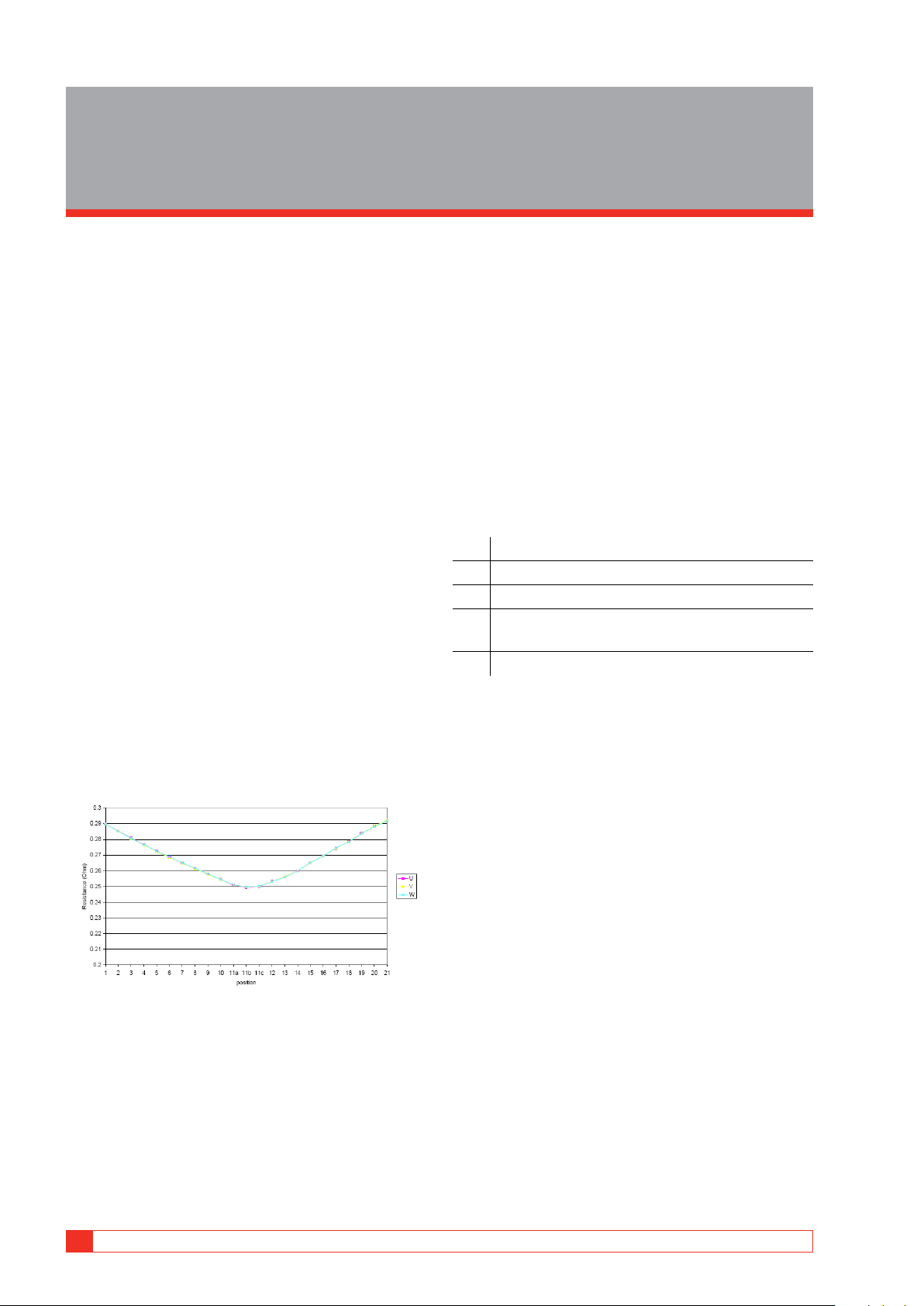
Winding resistance measurements (WRM) are
normally performed for every tap the same way as
WRM for individual windings. The test instrument is
continuously injecting test current and the resistances
for each tap are measured sequentially as the tap
changer is stepped through its positions. Results are
typically presented as a graph or table with resistance
values for each tap. Resistance changes between
taps should be consistent with only small deviations
between different tap position changes. Fig 1 shows
a typical behavior for a transformer/tap-changer in
as-new condition.
5.2 Temperature correction
Cold winding resistance measurements are normally
converted to a standard reference temperature equal
to the rated average winding temperature rise plus
20ºC. In addition, it may be necessary to convert
the resistance measurements to the temperature
at which the impedance loss measurements were
made. If winding resistances are to be compared to
factory values, resistance measurements will have
to be converted to the reference temperature used
at the factory (usually 75°C). The conversions are
accomplished by the following formula:
Rs = Rm ( Ts + Tk ) / ( Tm + Tk )
where:
Rs resistance at desired temperature Ts
Rm measured resistance
Ts desired reference temperature, in °C.
Tm temperature at which resistance was
measured, in °C.
Tk 235 (copper) 225 (aluminum)
Fig 5.1. Winding resistance vs tap position for a new transformer
Measuring the winding resistance for each individual
tap is quite straightforward. The most common
issue is probably that the tester has not waited for a
sufficient time for taking measurements after a tap
change. Monitor the resistance value closely before
storing the value to make sure the resistance value has
stabilized!
14 MTO106 ZP-BN01E BN034794AE
Page 15

5.3 Manual
demagnetization of a
transformer
The MTO106 does not include and automated
demagnetization feature and demagnetization, if
deemed necessary, must be performed manually
according to the method below.
1] Run a normal winding resistance test accord-
ing to the instructions in section "4.2 Testing
Single and Dual windings" on page 12.
2] Swap the terminals, preferably by swapping
the Kelvin clamps, select the next lower test
current and inject current until the current
reading has reached at least 50% of the set
value.
3] Repeat step 2 for each test current range
down to the lowest selectable test current
value.
5 APPLICATION EXAMPLES
BN034794AE ZP-BN01E MTO106
15
Page 16

6 TROUBLESHOOTING AND CALIBRATION
Troubleshooting and
6
Calibration
6.1 Troubleshooting
Resistance
value
“----“ is
displayed
“< 0.010 mΩ”
is displayed
“< 0.10 mΩ”
“< 1.0 mΩ”
“< 0.010 Ω”
or
“< 0.10 Ω”
Voltage
value
U < 0.06
mV
U < 0.06
mV
U > 20 V
Current value Probable cause Action
Close to set value
0.0 A
Typical less than 50%
of set current value
1. Increase test
1. Too low test current
2. Sense leads switched
3. Sense leads not connected
4. Current leads shorted
No current loop, current leads
not properly connected
Too high test current Lower test current
Resistance below measurement
range
Too low test current Increase test current
current
2. Check sense leads
3. Check sense leads
4. Check current
leads
Check current leads
16 MTO106 ZP-BN01E BN034794AE
Page 17

7 SPECIFICATIONS
BN034794AE ZP-BN01E MTO106
17
Page 18

7 SPECIFICATIONS
Specifications
7
Specifications
Specifications are valid at nominal input voltage. Specifications are
subject to change without notice.
Environment
Application field The instrument is intended for use in
Temperature
Operating -20°C to +50°C (-4°F to +122°F)
Storage & transport -50°C to +70°C (-58°F to +158°F)
Humidity (operating) 0% – 90% RH, non-condensing
CE-marking
LVD 2014/35/EU
EMC 2014/30/EU
RoHS 2011/ 6 5 / E U
General
Mains voltage 100 - 240 V AC, 50 / 60 Hz
Input power 400 VA (max)
Case Ruggedized plastic case with removable lid
Dimensions (W x D x H) 360 x 304 x 194 mm (14.2 x12 x 7.6”)
Weight 7.3 kg (16 lbs) excl. cables
Display 4-inch, backlit, monochrome
Test l eads 2 x 10 m (33 ft), with banana connectors
Ground lead 1 x 5 m (16 ft), 2.5 mm²
Measurement section
Measurment range 10 µOhm to 30 kOhm
Resolution Up to 4 digits
Open circuit test voltage up to 48 V DC
Measurement voltage up to 20 V DC
Current
range
6 A 10.00 mΩ to 5.00 0 Ω ±(0.25%rdg + 1 digit) 4 digits
1 A 100.0 mΩ to 30.00 Ω ±(0.25%rdg + 1 digit) 4 digits
100 mA 1.000 Ω to 300.0 Ω ±(0.25%rdg + 1 digit) 4 digits
10 m A 10.00 Ω to 3000 Ω ±(0. 25%rdg + 1 digit) 4 digits
1 mA 100.0 Ω to 30.0 0 kΩ ±(0.25%rdg + 1 digit) 4 digits
Resistance range Inaccuracy Resolution
0.010 mΩ to 9.999 mΩ
0.10 mΩ to 99.99 mΩ ±(0.25%rdg + 2 digits) 0.01 m Ω
1.0 mΩ to 999.9 mΩ ±(0. 25%rdg + 2 digit s) 0 .1 m Ω
0.010 Ω to 9.999 Ω ±(0.25%rdg + 2 digits) 0.0 01 Ω
0.10 Ω to 99.99 Ω ±(0.25%rdg + 2 digits) 0.01 Ω
high-voltage substations and industrial
environments.
and carrying handle, IP 67 when closed
alphanumerical display
and Kelvin clamps
±(0.25%rdg + 2 digits) 0.001 mΩ
18 MTO106 ZP-BN01E BN034794AE
Page 19

Page 20

Your “One Stop” Source for all your electrical test equipment needs
▪ Battery Test Equipment
▪ Cable Fault Locating Equipment
▪ Circuit Breaker Test Equipment
▪ Data Communications Test Equipment
▪ Fiber Optic Test Equipment
▪ Ground Resistance Test Equipment
▪ Insulation Power Factor (C&DF) Test Equipment
▪ Insulation Resistance Test Equipment
▪ Line Testing Equipment
▪ Low Resistance Ohmmeters
▪ Motor & Phase Rotation Test Equipment
▪ Multimeters
▪ Oil Test Equipment
▪ Portable Appliance & Tool Testers
▪ Power Quality Instruments
▪ Recloser Test Equipment
▪ Relay Test Equipment
▪ T1 Network Test Equipment
▪ Tachometers & Speed Measuring Instruments
▪ TDR Test Equipment
▪ Transformer Test Equipment
▪ Transmission Impairment Test Equipment
▪ Watthour Meter Test Equipment
▪ STATES® Terminal Blocks & Test Switches
▪ Professional Hands-On Technical and
Safety Training Programs
Megger is a leading global manufacturer and supplier
of test and measurement instruments used within the
electric power, building wiring and telecommunication
industries.
With research, engineering and manufacturing facilities
in the USA, UK, Germany and Sweden, combined with
sales and technical support in most countries, Megger
is uniquely placed to meet the needs of its customers
worldwide.
Megger is certified according to ISO 9001 and 14001.
Megger is a registered trademark.
Megger Group Limited
UNITED KINGDOM
Dover, Kent CT17 9EN
ENGLAND
▪ AUSTRALIA
▪ BULGARIA
▪ CANADA
▪ CZECH REPUBLIC
▪ CHINA
▪ FRANCE
▪ GERMANY
▪ HUNGARY
▪ INDIA
▪ INDONESIA
▪ KINGDOM OF BAHRAIN
▪ KOREA
▪ MALAYSIA
▪ PAKISTAN
▪ POLAND
▪ ROMANIA
▪ RUSSIA
▪ SINGAPORE
▪ SLOVAK REPUBLIC
▪ SOUTH AFRICA
▪ SPAIN
▪ SWEDEN
▪ SWITZERLAND
▪ TAIWAN
▪ THAILAND
▪ UNITED ARAB EMIRATES
▪ USA
▪ VIETNAM
▪ PHILIPPINES
WWW.MEGGER.COM
Postal address:
Megger Sweden AB
Box 724
SE-182 17 DANDERYD
SWEDEN
T +46 8 510 195 00
F +46 8 510 195 95
Subject to change without notice. Printed matter No. ZP-BN01E Doc. BN034794AE V01a 2018
Visiting address:
Megger Sweden AB
Rinkebyvägen 19
SE-182 36 DANDERYD
SWEDEN
seinfo@megger.com
www.megger.com
 Loading...