

Page 1

M
MTB7671/2
Test box
User Guide
Page 2

G Safety warnings
Safety Warnings and Precautions must be read and
understood before the instrument is used. They must be
observed during use.
Only use the MTB7671/2 when both polarity indicator
LEDs are lit.
The MTB7671/2 is protected by an integral RCD plug which
MUST NOT be removed from the tester.
The interlock protected 13 A socket should only be used with
double insulated RCD and Loop testers.
The instrument should not be used if any part of it is damaged.
Replacement fuses must be of the correct type and rating. Failure
to fit the correctly rated fuse may result in a safety hazard.
Only shrouded test leads should be used when measuring the
230 V a.c. mains supply
Users of this equipment and/or their employers are reminded that Health and
Safety Legislation requires them to carry out valid risk assessments of all electrical
work so as to identify potential sources of electrical danger and risk of electrical
injury such as inadvertent short circuits
CAT II - Measurement category II: Equipment connected between the
electrical outlets and the user’s equipment.
CAT III - Measurement category III: Equipment connected between the
distribution panel and the electrical outlets.
CAT IV - Measurement category IV: Equipment connected between the origin
of the low-voltage mains supply and the distribution panel.
NOTE
THE INSTRUMENT MUST ONLY BE USED BY SUITABLY
TRAINED AND COMPETENT PERSONS.
Symbols used on the instrument:
F Caution: risk of electric shock
G Caution: refer to accompanying notes
t Equipment protected throughout by Double Insulation (Class II)
c Equipment complies with relevant EU Directives
Equipment complies with ‘C tick’ requirements
Do not dispose of in the normal waste stream
Page 3
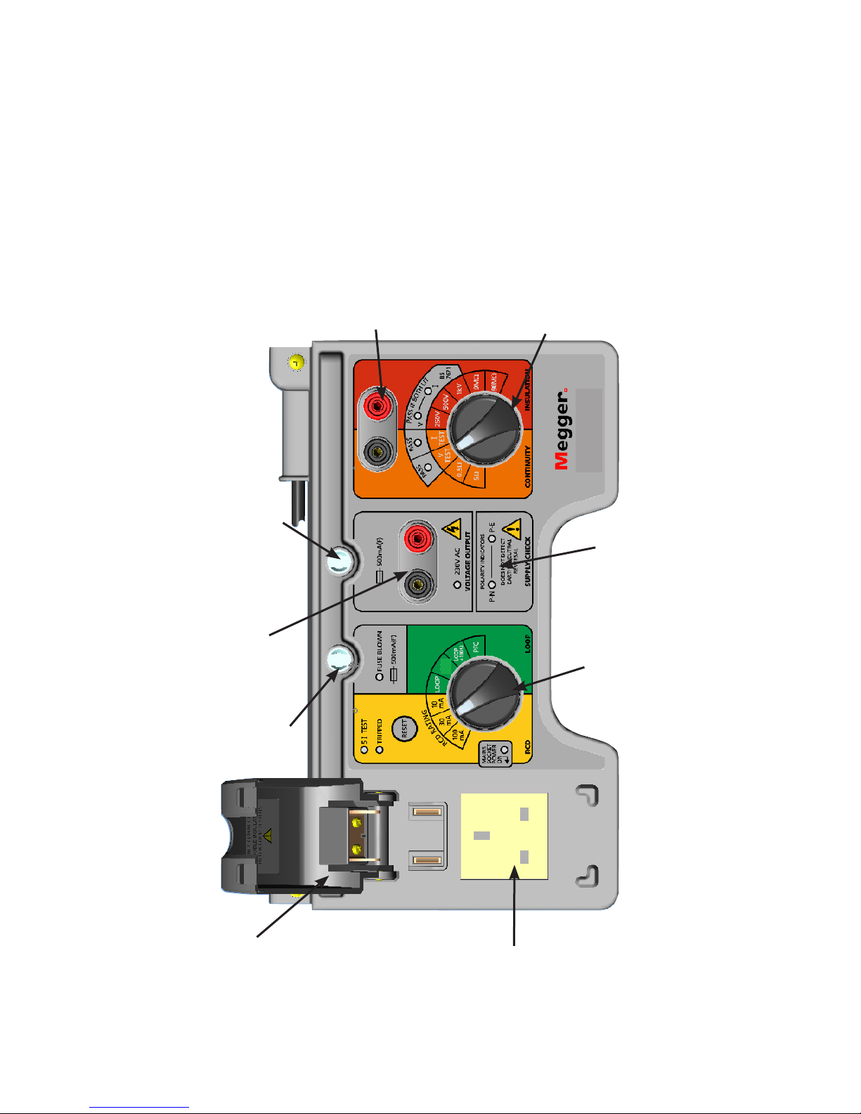
Interlock cover
AC out supply
Fuse
Fuse
RCD and loop
test supply
socket
Continuity and
insulation test
select switch
Continuity
and insulation
connection
sockets
Supply
check
indicators
RCD and loop
test select switch
MTB7671/2
LOOP
+10Ω
Page 4

OPERATION
The MTB7671/2 is intended for use with double insulated test
instruments only.
The MTB7671/2 has a combined earth and neutral which stops
it from tripping RCD protected circuits. To prevent the danger of
electric shock the MTB7671/2 is protected by a RCD plug and uses
a safety interlock for all live circuit tests.
1. SWITCHING ON
To switch on the MTB7671/2, plug the unit into the 230 V 50 Hz
mains supply using the integral RCD plug and depress the button
on the top of this plug and release, this will switch the plug on.
The bars on the plug should show red to indicate the unit is powered and the supply LEDs on the MTB7671/2 will be on.
To test the RCD plug, lightly press the button on the top (‘Test’
button). The red indicator bars should disappear and the supply
LEDs on the MTB7671/2 go out.
2. SUPPLY POLARITY CHECK
2.1 Supply Pass
The supply polarity check section on the MTB7671/2 should be on,
showing 2 green LEDs.
Do not use the test box unless both of these LEDs are lit.
NOTE: The polarity check will not detect if neutral and earth are
reversed.
3. AC Voltage output
The unit provides connection to the input mains supply to provide
a voltmeter check. The status of this supply is indicated by the
[230 V AC] LED. If this is not lit then the protection fuse has blown
and will need to be replaced.
Connect the tester to the voltage output terminals.
✍- Record the reading on the record card.
Page 5

4. TESTING A CONTINUITY TESTER
Connect the tester to the continuity and insulation connection sockets in the orange and red section of the test box.
Warning: Do not apply more than 250 mA.
4.1 Current Test
Set the continuity and insulation test select switch to [I TEST] and
perform a continuity test. If the test instrument delivers more than
200 mA the [I TEST] pass LED will light.
✍- Record the reading on the record card.
4.2 Voltage Test
Set the continuity and insulation test select switch to [V TEST] and
perform a continuity test.
If the open circuit voltage from the tester is between 4 V and 24 V dc
the [V TEST] pass LED will light.
NOTE: The MFT1700 will require the buzzer to be turned on during
this test.
✍- Record the reading on the record card.
NOTE: If in either of the tests listed above the LEDs fail to light, the
test instrument under test should be returned for a full calibration.
4.3 0.5 Ω Test
Set the continuity and insulation test select switch to [0.5 Ω] and
perform a continuity check. This connects a resistor between the test
sockets of 0.5 Ω +/-3%. The tester should indicate a measured value
of 0.5 Ω (+/- operational errors including the tester’s accuracy).
✍ - Record the reading on the record card.
4.4 5.0 Ω Test
Set the continuity and insulation test select switch to [5 Ω] and
perform a continuity check. This connects a resistor between the test
sockets of 5 Ω +/-3%. The tester should indicate a measured value of
5 Ω (+/- operational errors including the test instrument’s accuracy).
✍ - Record the reading on the record card.
4.5 If an instrument fails the above tests, refer to note 5.6 for reverse
polarity instruments.
Page 6

5. TESTING AN INSULATION TESTER
Connect the test instrument to the continuity and insulation connection sockets in the orange and red section of the test box.
Warning: Do not apply more than 1250 V d.c.
5.1 Voltage load test @ 250 V
Set the continuity and insulation test select switch to [250 V] and perform an insulation test with the test instrument set to 250 V output.
If the test voltage is 250 V d.c. the [V] LED will be on. If the current
delivered from the unit is greater than 1 mA the [I] LED will also be
on, showing that the test criteria have been met. A fixed resistor of
0.25 MΩ +/-3% is used to provide the test reference. The test instrument should indicate a measured value of 0.25 MΩ (+/- operational
errors including the test instrument’s accuracy).
If either of the LEDs fail to light the test instrument should be returned for a full calibration.
✍ Record the reading on the record card.
5.2 Voltage load test @ 500 V
Set the continuity and insulation test select switch to [500 V] and perform an insulation test with the test instrument set to 500 V output.
If the test voltage is 500 V d.c. the [V] LED will be on. If the current
delivered from the unit is greater than 1 mA the [I] LED will also be
on, showing that the test criteria have been met. A fixed resistor
of 0.5 MΩ +/-3% is used to provide the test reference. The tester
should indicate a measured value of 0.5 MΩ (+/- operational errors
including the test instrument’s accuracy).
If either of the LEDs fail to light the tester should be returned for a
full calibration.
✍ Record the reading on the record card.
5.3 Voltage load test @ 1 kV
Set the continuity and insulation test select switch to [1 kV] and perform an insulation test with the test instrument set to 1 kV output.
If the test voltage is 1 kV dc the [V] LED will be on. If the current delivered from the unit is greater than 1 mA the [I] LED will also be on,
showing that the test criteria have been met. A fixed resistor of
Page 7

1 MΩ +/-3% is used to provide the test reference. The tester should
indicate a measured value of 1 MΩ (+/- operational errors including
the tester’s accuracy).
If either of the LEDs fail to light the tester should be returned for a
full calibration.
✍ Record the reading on the record card.
5.4 9 MΩ Test
Set the continuity and insulation test select switch to [9 MΩ] and
perform an insulation check using the tester. This connects a
9.0 MΩ +/-3% resistor between the test sockets. This test can be
performed at any voltage up to 1 kV. The tester should indicate
a measured value of 9.0 MΩ (+/- operational errors including the
tester’s accuracy).
✍ Record the reading on the record card.
5.5 90 MΩ Test
Set the continuity and insulation test select switch to [90 MΩ] and
perform an insulation check using the tester. This connects a 90 MΩ
+/-3% resistor between the test sockets. This test can be performed
at any voltage up to 1 kV. The tester should indicate a measured value of 90 MΩ (+/- operational errors including the tester’s accuracy).
✍ Record the reading on the record card.
5.6 In some instances contintuity and insulation testers have reversed
outputs. If the voltage and current LEDs are not lit when checking
the testers outputs it is recommended that you reverse the polrity
connections i.e. connect the RED test lead to the black continuity/
insulation socket and the BLACK test lead to the RED continuity/insulation socket and repeat the tests.
Page 8

6. TESTING A LOOP TESTER
Connect the tester to the RCD and loop test supply socket. When
the interlock cover is closed, the earth pin of this socket is connected
to the supply neutral.
Note: The MTB7671/2 can be used to perform either ‘No Trip’ or
‘High Current’ loop tests.
6.1 Conducting a Loop Test
Set the RCD and loop test select switch to [Loop] and perform a loop
test using the tester. This returns a value for the initial test conditions.
✍ Record the reading on the record card
6.2 Conducting a +10 Ω Loop Test
Set the RCD and loop select switch to [Loop + 10 Ω] and perform a
loop test using the tester. Check that the loop impedance reading
has increased from the reading in 6.1 by a nominal 10 Ω.
NOTE: allow at least 10 seconds between tests if conducting a high
current loop test.
✍- Record the reading on the record card.
6.3 Conducting a +180 Ω loop test
Set the RCD and loop select switch to [Loop + 180 Ω] and perform
a loop test using the tester. Check that the loop impedance reading
has increased from the reading in 6.1 by a nominal 180 Ω.
✍- Record the reading on the record card.
NOTE: Some 3 wire loop testers give a >50 V touch voltage on this
range. A 2 wire test can be used for calibration checks.
6.4 Performing a PFC test
Set the RCD and loop select switch to [PFC] and perform a loop test
using the tester. The tester will perform a PFC test using
[Loop + 10 Ω] circuit.
NOTE: allow at least 10 seconds between tests if conducting a high
current PFC test.
✍ Record the result on the record card
NOTE: The MTB7671/2 performs a real loop test, the test results for
which can vary from test to test, particularly with ‘No Trip’ tests. It
is recommended that several (No Trip) tests are performed and the
average result recorded.
Page 9

7. TESTING AN RCD TESTER
Connect the tester to the RCD and loop test supply socket. When the
interlock cover is closed, the earth pin of this socket is connected to
the supply neutral.
7.1 Pre-Test Setup
Set the RCD test current on the tester and move the RCD and loop
test select switch to the appropriate position (e.g.10 mA, 30 mA or
100 mA). Check that the “mains socket power on” LED is lit. If not
then press the [reset] button.
7.2 Conducting 1/2 I Test
To perform a 1/2 I test set the tester to 1/2 I mode and perform the
test. The tester should not indicate a tripped RCD (if it does then it
should be returned for a full calibration). This can be repeated for
180° 1/2 I if provided on tester.
- Record the results on the record card
7.3 Conducting an I @ 0° Test
To perform a 0° I test set the tester to 0° I mode and perform the
test. The test box will trip and disconnect power. The [Tripped] LED
will light. The trip time should be a nominal 40 ms.
If the tester fails to indicate a tripped RCD then the tester should be
returned for a full calibration.
✍- Record the reading on the record card.
To reset the test box press the [reset] button in the yellow panel.
7.4 Conducting an I @ 180° Test
To perform a 180° I test set the tester to 180° I mode and perform
the test. The test box will trip and disconnect power. The [Tripped]
LED will light. The trip time should be a nominal 50 ms.
If the tester fails to indicate a tripped RCD then the tester should be
returned for a full calibration.
✍- Record the reading on the record card.
To reset the test box press the [reset] button in the yellow panel.
7.5 Conducting a 5I @ 0° Test
To perform a 0° 5I test set the tester to 0° 5I mode and perform the
test. The test box will trip and disconnect power. The [Tripped] and [5
I TEST] LEDs will light. The trip time should be a nominal 10 ms.
Page 10

If the tester fails to indicate a tripped RCD then the tester should be
returned for a full calibration.
✍- Record the reading on the record card.
To reset the test box press the [reset] button in the yellow panel.
7.6 Conducting a 5I @ 180° Test
To do a 180° 5I test set the tester to 180° 5I mode and perform the
test. The unit will trip and disconnect power. The [Tripped] and
[5 I TEST] LEDs will light. The trip time should be a nominal 20 ms.
If the tester fails to indicate a tripped RCD then the tester should be
returned for a full calibration.
✍- Record the reading on the record card.
To reset the test box press the [reset] button in the yellow panel.
7.7 Conducting 10 mA, 30 mA and 100 mA tests
The test sequence can be repeated for the 10 mA, 30 mA and
100 mA tests by selecting the appropriate current setting on the RCD
and loop test select switch and repeating the tests as described in
sections 7.2 to 7.6.
NOTE: RCD Protection
In order to protect the current sense circuit the RCD simulator is
protected by a 500 mA fuse. If the fuse blows then the earth pin of
the RCD and loop supply socket will float. If an RCD test is attempted
the fuse blown LED will light. Note that this will only illuminate if the
test instrument does not inhibit testing if the correct voltages are not
present, or the test instrument provides sufficient leakage to light the
LED when connected.
8. Fuse replacement
The MTB77671/2 is protected by two x 500 mA (F) fuses and a 7 A
fuse in the RCD plug. Fuse failure is indicated by either the 230 V
AC LED failing to light or the [Fuse Blown] LED lighting. In the event
of a fuse failing, fuses must be replaced with the same fuse type.
Disconnect the test box from the mains supply. Disconnect any test
instruments from the test box. Remove the failed fuse from the fuse
holder and replace with an identical fuse:
Fuse Type: 500 mA (F) 20 mm
7 A BS1362
Page 11

BS7671
&
BS EN61557
MTB7671
tester
requirements
Megger test
parameters
Calibration
points
Continuity short
Circuit test
Current
>200 mA >200 mA
Pass/Fail indication
(Threshold limits ±2%)
>200 mA
Continuity test
Voltage range
4 V - 24 V 4 V - 24 V
Pass/Fail indication
(Threshold limits ±2%)
Continuity
resisitance
0.5 Ω ±3% 0.5 Ω
Continuity
resisitance
5.0 Ω ±3% 5.0 Ω
Insulation test
current
1 mA 1 mA
Pass/Fail
indication
(Threshold limits ±2%)
Insulation test
voltages
250 V +25%
max
500 V +25%
max 1 kV
+25% max
250 V +25%
500 V +25%
1 kV +25%
Pass/Fail indication
(Threshold limits ±2%)
Insulation test
resistances
0.25 MΩ min
0.5 MΩ min
1 MΩ min
0.25 MΩ ±3%
0.5 MΩ ±3%
1 MΩ ±3%
0.25 MΩ
0.5 MΩ
1.0 MΩ
Insulation test
resistances
9 MΩ ±3%
90 MΩ ±3%
9 MΩ
90 MΩ
Loop Local mains impedance
Loop + 10 Ω Loop + 10 Ω (±5%)10
Ω
Loop + 180 Ω
(IEE On-site
guide 10.3.5
Earth electrode
resistance)
Loop + 180º (±5%) 180 Ω
RCD currents (I) 10 mA, 30 mA & 100
mA
RCD No trip
(1/2 I)
No trip >1999 ms
RCD (I) <200 ms 40 ms @ 0º
50 ms @ 180º
RCD (5 x I) <40 ms 10 ms @ 0º
20 ms @ 180
Page 12

Mains Supply
230 V 50 Hz 10 VA. This will increase when performing a loop test.
Fuses RCD plug 7 A (BS1362)
MTB7671/2 500 mA F 250 V IEC60127
Size 320 x 280 x 100 mm
Weight 2.2 kg
EMC In accordance with IEC 61326-1
Operation
Safety Meets the requirements of IEC61010-1. Refer to
safety warnings supplied.
Environment Conditions
The MTB7671/2 is intended for indoor use only.
Cleaning
Wipe disconnected instrument with a clean cloth moistened with
soapy water or Isopropyl Alcohol (IPA).
Accessories
Description Order Code
Test Record Cards 2002-524
Page 13

REPAIR AND WARRANTY
The instrument contains static sensitive devices, and care must be taken in
handling the printed circuit board. If an instrument’s protection has been
impaired it should not be used, but sent for repair by suitably trained and
qualified personnel. The protection is likely to be impaired if for example; it
shows visible damage; fails to perform the intended measurements; has been
subjected to prolonged storage under unfavourable conditions, or has been
subjected to severe transport stresses.
NEW INSTRUMENTS ARE GUARANTEED FOR 1 YEAR FROM THE
DATE OF PURCHASE BY THE USER.
Note: Any unauthorized prior repair or adjustment will automatically
invalidate the Warranty.
INSTRUMENT REPAIR AND SPARE PARTS
For service requirements for Megger Instruments contact:
Megger Limited or Megger
Archcliffe Road Valley Forge Corporate Centre
Dover 2621 Van Buren Avenue
Kent CT17 9EN Norristown PA 19403
England. U.S.A.
Tel: +44 (0) 1304 502 243 Tel: +1 610 676 8579
Fax: +44 (0) 1304 207 342 Fax: +1 610 676 8625
or an approved repair company.
UKrepairs@megger.com
Returning and Instrument for Repair
If it is necessary to retun an instrument for repair, a Returns Authorisation
number must first be obtained by contacting one of the addresses shown.
You will be asked to provide key information, such as the instrument serial
number and fault reported when the number is issued. This will enable the
Service Department to prepare in advance for the receipt of your instrument,
and to provide the best possible service to you.
The Returns Authorisation number should be clearly marked on the outside of
the product packaging, and on any related correspondence. The instrument
should be sent, freight paid to the appropriate address. If appropriate a copies
of the original purchase invoice and of the packing note, should be sent
simultaneously by airmail to expedite clearance through customs.
For instruments requiring repair outside the warranty period a repair estimate will be
submitted to the sender, if required, before work on the instrument commences.
Approved Repair Companies
Megger operates fully traceable repair and calibration facilities complemented
by a network of approved repair and calibration companies, to offer excellent
in-service care for your Megger products. Megger’s streamlined Returns
Authorization system ensures your product is expected and enables you to
track its progress on-line.
Page 14

M
Megger Limited
Archcliffe Road, Dover
Kent CT17 9EN England
T +44 (0)1 304 502101
F +44 (0)1 304 207342
E uksales@megger.com
Megger
Z.A. Du Buisson de la Couldre
23 rue Eugène Henaff
78190 TRAPPES France
T +33 (0)1 30.16.08.90
F +33 (0)1 34.61.23.77
E infos@megger.com
Megger Pty Limited
Unit 26 9 Hudson Avenue
Castle Hill
Sydney NSW 2125 Australia
T +61 (0)2 9659 2005
F +61 (0)2 9659 2201
E ausales@megger.com
Megger Limited
110 Milner Avenue Unit 1
Scarborough Ontario M1S 3R2
Canada
T +1 416 298 9688 (Canada only)
T +1 416 298 6770
F +1 416 298 0848
E casales@megger.com
Megger products are distributed in 146 countries worldwide.
This instrument is manufactured in the United Kingdom.
The company reserves the right to change the specification or
design without prior notice.
Megger is a registered trademark
Part No. MTB7671_2_2002-525_V04 11/13
www.megger.com
 Loading...