

Page 1
www . ElectricalPartManuals . com
User
Manual
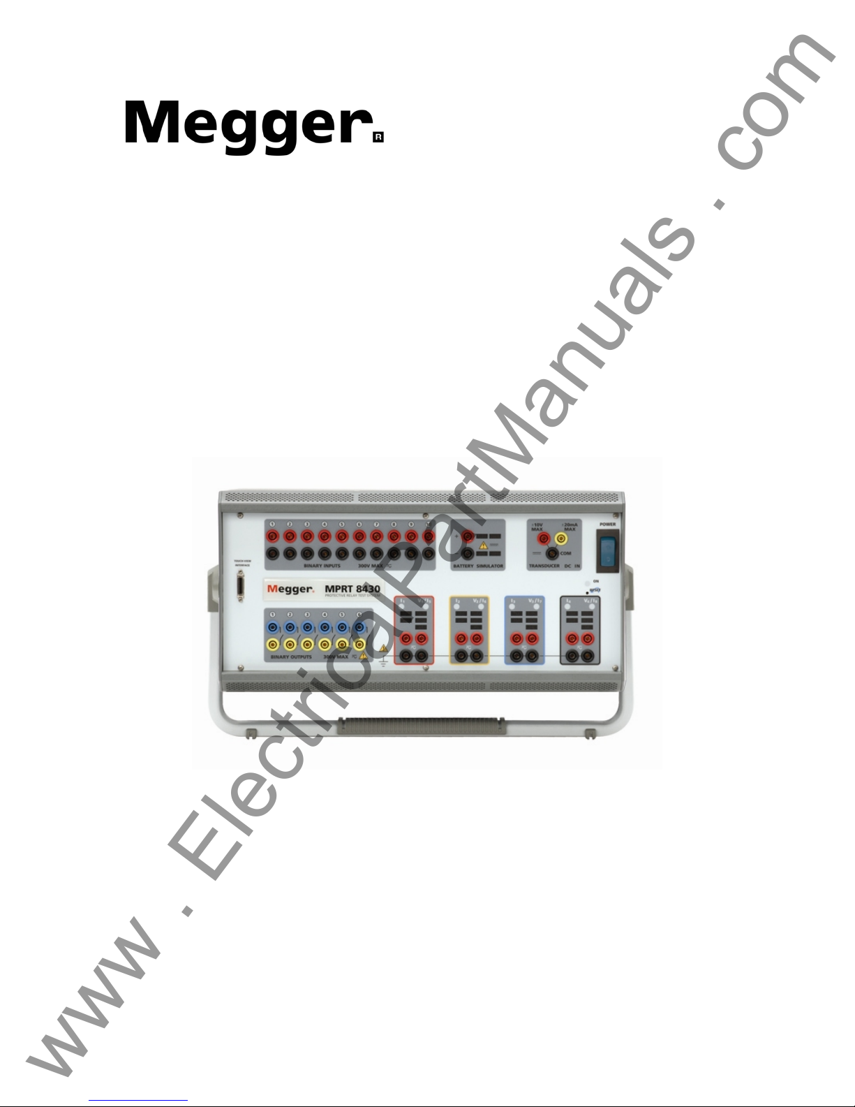
Model MPRT
Megger Protective Relay Tester
Part 710000
Rev 3 Date 11/15/2005
* MPRT shown with optional large carry handle
Page 2

Revision History
www . ElectricalPartManuals . com
Revision
1 Initial Release 12/17/2003
2 30043 3/07/2005
3 30207 11/16/2005
This manual, as well as the hardware and software described in it, is furnished under license and
may be used or copied only in accordance with the terms of such license. The content of this
manual is furnished for informational use only, is subject to change without notice. Megger
assumes no responsibility or liability for any errors or inaccuracies that may appear in this
manual.
The information and data in this User Manual are proprietary. The equipment described herein
may be protected by U.S. patents. Megger specifically reserves all rights to such proprietary
information as well as rights under any patent, none of which is waived by the submission of this
user manual.
ECN # Date
IMPORTANT
2
Page 3

www . ElectricalPartManuals . com
Except as permitted by such license, no part of this publication may be reproduced, stored in a
retrieval system, or transmitted, in any form or by any means, electronic, mechanical, recording,
or otherwise, without the prior written permission of Megger.
Megger, the Megger logo are trademarks of Megger. VXWorks, Zinc, and Tornado are either
registered trademarks or trademarks of the WindRiver Corporation in the US and other countries.
Adobe, the Adobe logo, and Adobe Reader are trademarks of Adobe Systems Incorporated. All
other trademarks are the property of their respective owners.
Notice to U.S. government end users. The hardware, software and documentation are
“commercial items”, as that term is defined at 48 C.F.R. §2.101, consisting of “commercial
computer software” and “commercial computer software documentation,” as such terms a re u sed
in 48 C.F.R. §12.212 or 48 C.F.R. §227.7202, as applicable. Consistent with 48 C.F.R. §12.212
or 48 C.F.R. §§227.7202-1 through 227.7202-4, as applicable, the commercial computer software
and commercial computer software documentation are being licensed to U.S. government end
users (1) only as commercial items and (2) with only those rights as are granted to all other end
users pursuant to the terms and conditions set forth in the Megger standard commercial
agreement for this software and hardware. Unpublished rights reserved under the copyright laws
of the United States. The recipient, if a Government agency, acknowledges that this manual and
the equipment described were procured with "Limited Rights" to technical data as described in
ASPR 9-203 (b).
The MPRT test set includes an RTOS-resident computer program. This program belongs to
Megger and contains trade secret ideas and information of Megger.
Written and designed at Megger, 4271 Bronze Way, Dallas, Texas 75237.
__________________________
Printed in the USA.
© 2003, 2005 Megger. All rights reserved.
3
Page 4
SAFETY PRECAUTIONS
www . ElectricalPartManuals . com
WARNING:
VOLTAGES GENERATED BY THIS INSTRUMENT CAN BE HAZARDOUS
This instrument has been designed for operator safety; however, no design can
completely protect against incorrect use. Electrical circuits are dangerous and can be
lethal when lack of caution and poor safety practices are used. There are several
standard safety precautions that should be taken by the operator. Where applicable, IEC
safety markings have been placed on the instrument to notify the operator to refer to the
user manual for instructions on correct use or safety related topics. Refer to the following
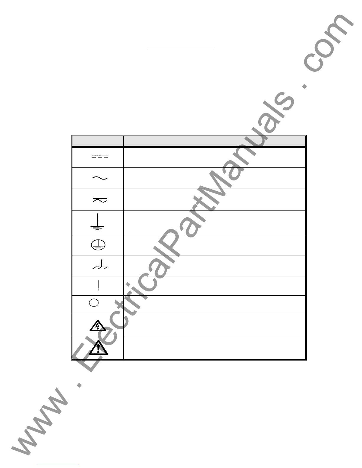
table of symbols and definitions.
Symbol Description
Direct Current
Alternating Current
Both direct and alternating current
Earth (ground) Terminal. There is a common chassis ground
terminal located on the back panel (see Back Panel under
Description of Controls.
Protective Conductor Terminal
Frame or Chassis Terminal
On (Supply)
Off (Supply)
Caution, risk of electric shock
Caution (refer to accompanying documents)
WARNING: Under no circumstances should the operator or technician attempt to open or
service this instrument while connected to a power source. Lethal voltages are present
and may cause serious injury or death!
4
Page 5

SAFETY PRECAUTIONS (Continued)
www . ElectricalPartManuals . com
The following are some specific safety related items associated with the
MPRT test system.
Always start with the power OFF, before connecting the power cord.
Make sure outputs are off before attempting to make test
connections.
Always use properly insulated test leads. The test leads supplied
with the unit are rated for the continuous output ratings of the test
system, and should be properly used and cared for. DO NOT use
cracked or broken test leads.
Always turn the test system off before disconnecting the power cord
or removing / inserting output modules. Turn the power off when
removing or inserting the Voltage / Current module(s).
DO NOT power up without the modules secured in their respective
slot.
DO NOT attempt to use the unit without a safety ground connected.
DO NOT attempt to use the unit if the power cord ground prong is
broken or missing.
Under no circumstances should the operator put their hand or
tools inside the test system chassis area with the test system
connected to a power source. Lethal voltages are present and
may cause serious injury or death!
5
Page 6

Table of Contents
www . ElectricalPartManuals . com
Section Page
Revision History ............................................................................................................................ 2
Safety Precautions........................................................................................................................ 4
1.0 Operation........................................................................................................................... 11
1.1 Control Description.......................................................................................................... 11
1.1.1 Front Panel...................................................................................................................... 11
1.1.2 Rear Panel...................................................................................................................... 12
1.1.3 Touch View Interface ...................................................................................................... 14
1.2 Terminology ...................................................................................................................... 15
1.2.1 Acronyms ........................................................................................................................ 15
1.2.2 Glossary of Terms........................................................................................................... 15
1.2.2.1 Tap............................................................................................................................... 15
1.2.2.2 Time Dial ..................................................................................................................... 16
1.2.2.3 Instantaneous (Inst.) Tap............................................................................................. 16
1.2.2.4 Reset Time.................................................................................................................. 16
1.2.2.5 Target Tap...................................................................................................................16
1.2.2.6 Test Multiple................................................................................................................ 16
1.2.2.7 Reach.......................................................................................................................... 16
1.2.2.8 Torque......................................................................................................................... 16
1.2.2.9 Operation (Op) Time.................................................................................................... 16
1.2.2.10 Winding Number............................................................................................................. 17
1.2.2.11 Percent (%) Slope .......................................................................................................... 17
1.2.2.12 Percent (%) Harmonic....................................................................................................17
1.3 Touch View Interface (TVI)............................................................................................... 17
1.4 Input Power and Control..................................................................................................... 17
1.4.1 Input Power.....................................................................................................................17
1.4.2 Control Section................................................................................................................ 17
1.4.2.1 V/I Generator Module.................................................................................................. 17
1.4.2.1.1 Voltage and Current Ranges................................................................................... 18
1.4.2.1.1.1 Model 8415 (each output module)........................................................................... 18
1.4.2.1.1.2 Model 8430 (each output module)........................................................................... 18
1.4.2.1.2 Frequency Ranges................................................................................................... 18
1.4.2.1.3 Phase Angle............................................................................................................. 18
1.5 Timer Control .................................................................................................................... 18
1.5.1 Binary Inputs – Timer...................................................................................................... 19
1.5.1.1 Start, Stop, and Monitor Gates.................................................................................... 19
1.5.1.1.1 Dry Contacts Open.................................................................................................. 19
1.5.1.1.2 Dry Contacts Close.................................................................................................. 19
1.5.1.1.3 Application or Removal of AC or DC voltage........................................................... 19
1.5.2 Binary Outputs – Timer.................................................................................................... 20
1.6 Battery Simulator.............................................................................................................. 20
1.7 Transducer DC IN Measuring Circuit.............................................................................. 20
1.8 Operation of Optional High Current Interface................................................................ 20
2.0 SETUP................................................................................................................................20
2.1 System...............................................................................................................................20
2.2 Touch View Interface Operation...................................................................................... 21
2.2.1 Touch Panel Display....................................................................................................... 22
2.2.1.1 Keypad Entry...............................................................................................................22
2.2.1.2 Alphanumeric Keypad ................................................................................................. 22
2.2.2 Control Knob................................................................................................................... 22
2.2.3 Factory Defaults..............................................................................................................23
2.2.3.1 Language..................................................................................................................... 23
6
Page 7

2.2.3.2 Color Palette................................................................................................................ 23
www . ElectricalPartManuals . com
2.2.3.3 Brightness.................................................................................................................... 23
2.2.3.4 About - Information Screen ......................................................................................... 24
2.2.3.5 Date and Time............................................................................................................. 24
2.2.3.6 Battery Simulator Setting............................................................................................. 24
2.2.3.7 IP Address...................................................................................................................24
2.2.3.8 Serial Port.................................................................................................................... 24
2.2.3.9 GPIB Address.............................................................................................................. 25
2.2.3.10 Convertible V/I Control ................................................................................................ 25
2.2.3.11 Phase Angle Setting.................................................................................................... 25
2.2.3.12 System Frequency....................................................................................................... 26
2.2.3.13 Default Current Output ................................................................................................ 26
2.2.3.14 Default Voltage Output................................................................................................26
2.2.4 File Management ............................................................................................................ 27
2.2.4.1 Test Files.....................................................................................................................27
2.2.4.2 Test Results................................................................................................................. 27
2.3 Communication Ports ...................................................................................................... 27
2.3.1 RS-232C Serial Port........................................................................................................ 28
2.3.2 IEEE-488 GPIB............................................................................................................... 28
2.3.3 Ethernet 10 BaseT.......................................................................................................... 28
2.3.4 USB Port ......................................................................................................................... 28
2.3.5 Printer Port......................................................................................................................28
2.4 Error Reporting.................................................................................................................28
2.5 Advanced Visual Test Software (AVTS)......................................................................... 28
3.0 OPERATING PROCEDURES............................................................................................ 28
3.1 Touch View Interface........................................................................................................ 28
3.2 Setting Phase Angle Relationships................................................................................ 29
3.3 Current Sources................................................................................................................ 31
3.3.1 Parallel Operation ........................................................................................................... 31
3.3.2 Currents in Series Operation .......................................................................................... 32
3.3.3 Harmonic Restraint Test................................................................................................. 33
3.3.3.1 Basic Harmonic Restraint Test Proced ure..................................................................34
3.4 Voltage Sources................................................................................................................ 35
3.4.1 Outputs Summed Together............................................................................................. 35
3.4.2 Dynamic Voltage Relay Test........................................................................................... 35
3.4.3 3Ø, 3-Wire, Open-Delta and T-Connection..................................................................... 35
3.4.3.1 Open Delta .................................................................................................................. 35
3.4.3.1.1 Voltage Output Connections.................................................................................... 36
3.4.3.2 T-Connection............................................................................................................... 37
3.4.4 3Ø, 4-Wire, Y-Connection............................................................................................... 39
3.5 Internal Software Test Profiles........................................................................................ 40
3.5.1 Pulse Ramping................................................................................................................ 40
3.5.2 Ramping.......................................................................................................................... 40
3.5.3 Angle of Torque............................................................................................................... 41
3.5.4 Step................................................................................................................................. 41
3.5.5 Dynamic Frequency Hz/S ............................................................................................... 42
3.5.6 Auto Synchronizing......................................................................................................... 43
3.5.7 Pickup.............................................................................................................................. 43
3.5.8 Seal-In (Target)............................................................................................................... 44
3.5.9 Timing.............................................................................................................................. 44
3.5.10 Harmonic Restraint......................................................................................................... 44
3.5.11 Slope............................................................................................................................... 44
3.5.12 Through Fault.................................................................................................................. 44
3.5.13 Polarizing........................................................................................................................ 44
3.6 Timer..................................................................................................................................45
Basic Timer Setup Menu............................................................................................................ 45
7
Page 8

Description............................................................................................................................... ..45
www . ElectricalPartManuals . com
Controls...................................................................................................................................... 45
Complex Timer Setup Menu...................................................................................................... 47
Description............................................................................................................................... ..47
3.7 Battery Simulator.............................................................................................................. 47
3.8 Relay Testing .................................................................................................................... 47
3.8.1 Touch View Interface Graphical User Interface..............................................................48
3.8.1.1 Main Menu Screen ...................................................................................................... 48
3.8.1.2 Pre-set Test Menu....................................................................................................... 49
3.8.2 Impedance Relay Testing Menu .................................................................................. 50
3.8.2.1 Impedance Relay Setting Screen................................................................................ 51
3.8.2.2 The Reach Test Setting Screen.................................................................................. 52
3.8.2.3 Impedance Relay Pre-fault Setting Screen.................................................................53
3.8.2.4 Impedance Relay Reach Test Result Screen............................................................. 54
3.8.2.5 Impedance Relay Test Timing Settings....................................................................... 55
3.8.2.6 Impedance Relay Timing Test Result Screen............................................................. 56
3.8.2.7 Impedance Relay Angle of Torque Test Settings Screen...........................................58
3.8.2.8 Impedance Relay Angle of Torque Test Results Screen............................................59
3.8.2.9 Impedance Relay Target & Seal-In Test and Results................................................. 61
3.8.3 Overcurrent Relay Test Menu...................................................................................... 62
3.8.3.1 Over-Current Relay Setting Screen............................................................................. 63
3.8.3.2 Overcurrent Relay Test Configuration Screen............................................................ 64
3.8.3.3 Overcurrent Relay Pickup Test Results ...................................................................... 66
3.8.3.4 Overcurrent Relay Target & Seal-In Test Results....................................................... 67
3.8.3.5 Overcurrent Relay Instantaneous Test Results .......................................................... 68
3.8.3.6 Overcurrent Relay Timing Test Results ...................................................................... 69
3.8.4 Differential Relay Test Menu........................................................................................ 70
3.8.4.1 Differential Relay Setting Screen ................................................................................ 71
3.8.4.2 Differential Relay Test Configuration Screen..............................................................73
3.8.4.2 Differential Relay Winding 1, 2 or 3 Pick-Up Test Results.......................................... 75
3.8.4.3 Differential Relay Harmonic Restraint Test Results.................................................... 76
3.8.4.4 Differential Relay Slope Test Results.......................................................................... 77
3.8.4.5 Differential Relay Seal-In Test Results........................................................................ 78
3.8.4.6 Differential Relay Instantaneous Test Results............................................................ 79
3.8.4.7 Differential Relay Through Fault Test Results............................................................. 80
3.8.4.8 Differential Relay Polarizing Test Results................................................................... 81
3.8.5 Voltage Relay Test Menu.............................................................................................. 82
3.8.5.1 Voltage Relay Setting Screen ..................................................................................... 83
3.8.5.2 Voltage Relay Pickup Test Results............................................................................. 84
3.8.5.3 Voltage Relay Target & Seal-In Test Results.............................................................. 86
3.8.5.3 Voltage Relay Timing Test Results............................................................................. 87
3.8.6 Synchronous Relay Test Menu.................................................................................... 89
3.8.6.1 Synchronous Relay Setting Screen............................................................................. 90
3.8.6.2 Synchronous Relay Pickup Test Results .................................................................... 91
3.8.6.2.1 Testing Sync-Check, Synchronizing and Auto-Synchronizing Relays.................... 92
3.8.6.3 Synchronous Relay Timing.......................................................................................... 93
3.8.7 Power Relay Test Menu................................................................................................ 94
3.8.7.1 Power Relay Setting Screen ....................................................................................... 95
3.8.7.1.1 Test Configuration Screen.......................................................................................98
3.8.7.2 Power Relay Pickup Test Results............................................................................. 100
3.8.7.3 Power Relay Target & Seal-In Test and Results....................................................... 101
3.8.7.4 Power Relay Timing Test Results.............................................................................102
3.8.8 Reclose Relay Test Menu........................................................................................... 103
3.8.8.1 Reclose Relay Setting Screen................................................................................... 104
3.8.8.2 Reclose Relay Pickup Test Setting Screen............................................................... 105
3.8.8.3 Reclose Relay Timing Test Results .......................................................................... 106
8
Page 9

3.8.8.3.1 Testing Reclosing Relays - Theory of Operation................................................... 107
www . ElectricalPartManuals . com
3.8.8.3.2 Testing Reclosing Relays (Reclose Only), Timing and Sequence to Lockout ...... 110
3.8.8.3.3 Testing Distribution Relays with Trip, Reclosing and Sequence to Lockout......... 114
3.8.9 Frequency Relay Test Menu ...................................................................................... 118
3.8.9.1 Frequency Relay Setting Screen............................................................................... 119
3.8.9.2 Frequency Relay Pickup Test Results ...................................................................... 120
3.8.9.3 Frequency Relay Target & Seal-In Test Screen ....................................................... 120
3.8.9.4 Frequency Relay Timing Test Screen....................................................................... 122
3.8.9.4.1 Dynamic Frequency Timing Test........................................................................... 122
3.8.10 Manual Test Menu Screen.......................................................................................... 124
3.8.10.1 Manual Voltage/Current Test Screen..................................................................... 125
Description...............................................................................................................................125
Operation ................................................................................................................................. 125
Controls.................................................................................................................................... 125
3.8.10.2 Manual Frequency Test Settings Screen..............................................................128
Description...............................................................................................................................128
Operation ................................................................................................................................. 128
Controls.................................................................................................................................... 128
Dynamic Frequency Operation................................................................................................131
3.8.10.3 Manual Auto Synchronizing Test Screen..............................................................132
Description...............................................................................................................................132
Operation ................................................................................................................................. 132
Controls.................................................................................................................................... 132
Testing Synchronizing and Auto-Synchronizing Relays.......................................................... 133
3.8.10.4 Manual Transducer Test Settings Screen............................................................. 135
3.8.10.4.1 Select Transducer Type..................................................................................... 135
3.8.10.4.2 Transducer Description......................................................................................135
3.8.10.4.3 System Default Settings..................................................................................... 136
3.8.10.4.4 Transducer Output............................................................................................. 137
3.8.10.5 Manual Transducer Test Screen............................................................................ 139
3.8.10.5.1 MPRT Output Section........................................................................................139
3.8.10.5.2 Transducer Output Section................................................................................ 140
3.8.10.6 Testing Transducers...............................................................................................140
3.8.10.6.1 Saving Results.................................................................................................. 141
3.8.10.7 Watt / Var / Va / Power Factor Applications.......................................................... 141
3.8.10.7.1 Watt/VAR 1 Element..........................................................................................141
3.8.10.7.2 Power Factor 1 Element..................................................................................... 142
3.8.10.7.3 Watt/VAR1 1/2 Element.....................................................................................144
3.8.10.7.4 Watt/VAR 2 Element..........................................................................................145
3.8.10.7.5 Watt/VAR 2 1/2 Element....................................................................................147
3.8.10.7.6 Watt/VAR 3 Element..........................................................................................149
3.8.10.7.7 Power Factor 3 Element..................................................................................... 151
3.8.10.8 Single Phase Applications ..................................................................................... 152
3.8.10.8.1 AC and DC V oltage Transducers....................................................................... 152
3.8.10.8.2 AC and DC Current Transd ucers....................................................................... 153
3.8.10.8.3 Frequency Transducers..................................................................................... 154
4.0 External High Current Amplifier.................................................................................... 156
5.0 Warranty Statement........................................................................................................ 156
6.0 Service Data.................................................................................................................... 157
6.1 Preventive Maintenance................................................................................................. 157
6.1.1 Examine the Unit........................................................................................................... 157
6.2 MPRT Ethernet Port and IP Networks........................................................................... 157
6.2.1 Setting MPRT IP Address Dialog Box........................................................................... 158
6.2.2 Updating MPRT Software / Firmware........................................................................... 158
6.3 Service and Repair Instructions.................................................................................... 159
6.3.1 Basic Troubleshooting................................................................................................... 159
9
Page 10

6.3.1.2 Power Input............................................................................................................ 160
www . ElectricalPartManuals . com
6.3.1.3 Input Power and Control........................................................................................160
6.3.1.4 Binary Inputs and Battery Simulator...................................................................... 161
6.3.1.5 Voltage/Current Amplifier Module.......................................................................... 162
6.2.1.3 Input Power and Control........................................................................................162
6.4 Calibration Check........................................................................................................... 163
6.4.1 Checking Transducer DC IN.........................................................................................164
6.4.2 Checking Battery Simulator........................................................................................... 164
6.4.3 Checking AC Volts / DC Volts....................................................................................... 164
6.4.4 Checking AC Amperes / DC Amperes.......................................................................... 165
6.4.5 Checking AC Current – Convertible Channel............................................................... 166
6.4.6 Checking Phase Angle.................................................................................................. 167
6.4.7 Checking Frequency.....................................................................................................168
6.5 Preparation for Reshipment .......................................................................................... 168
10
Page 11
1.0 Operation
www . ElectricalPartManuals . com
The unit’s design is a "modular" concept. All controls and outputs are clearly marked and
logically grouped so continual reference to the instruction manual should not be necessary once
the test operator is acquainted with the operation of the test system. The unit’s rear panel will
appear different among units since each unit may have up to four V/I Generator Modules and
may have an optional EPOCH II / EPOCH 20 interface, or other type. However, there must be at
least one V/I Generator Module installed for this unit to operate properly.
1.1 Control Description
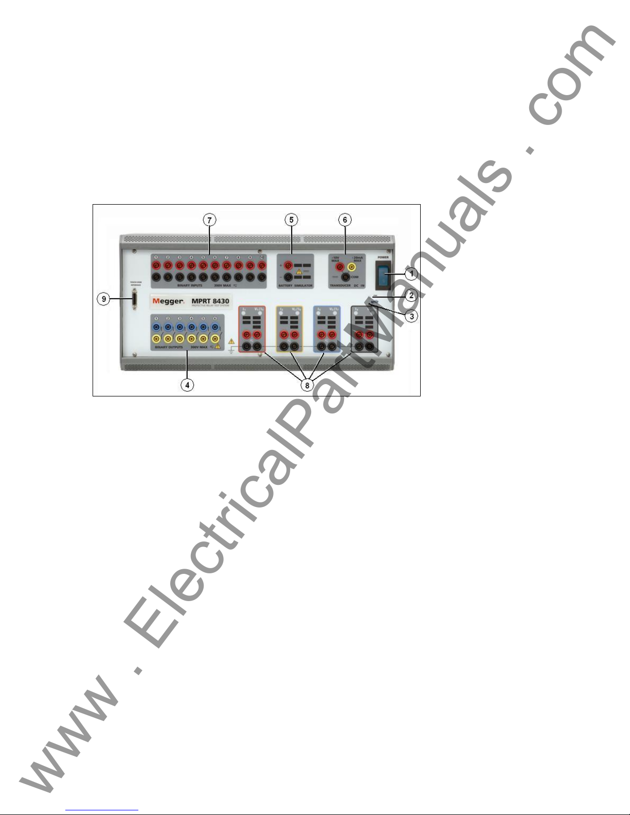
Figure 1 MPRT Front Panel
1.1.1 Front Panel
1. POWER ON/OFF Switch – used to switch unit on and off.
2. ON Light – indicates power is on when illuminated.
3. Reset Button – the reset button provides a soft reboot for the unit and restores the unit
to its normal Power-On state. The reset will clear all values entered into various screens.
The data should be saved before performing a reset, if possible.
4. Binary Outputs – there are 6 internal to the MPRT Unit. Each output can be configured
as Normally Open or Normally Closed contacts providing logic to the device under test.
The output can switch up to 300 VAC or 250 VDC with 1 Amp continuous. The
programmable wait duration is from 1 millisecond to 10,000 milliseconds.
5. Battery Simulator – the output voltages are 24, 48, 125 and 250 Volts DC with current
limiting output power protection. If a voltage is powered ON, that respective voltage will
have a lighted value.
6. Measurement (DC IN) – the DC IN will allow measurements up to ± 10 Volts DC or ± 20
milliamps of current.
7. Binary Inputs – there are 10 internal to the MPRT unit. The input will accept a voltage
range of 5 to 300 VAC or 5 to 250 VDC or dry Normally Open / Normally Closed contacts.
8. Three Phase Power Indication – the three phases are noted by the red, yellow, and
blue color boxes surrounding each output. Phase A (V1 & I1) is denoted by the red color;
11
Page 12
Phase B (V2 & I2) is denoted by the yellow color; and Phase C (V3 & I3) is denoted by
www . ElectricalPartManuals . com
the blue color. An optional fourth output module is denoted by the black color box. With a
fourth output module installed, there may be up to four phases of voltage and current, or
two three phase open delta voltages, with four currents, or up to eight phases of current.
The first four phases are indicated by V1/I1, V2/I2, V3/I3 and V4/I4. Once the voltage
generators are converted to current generators, they will change as indicated below:
V1 ⇒ I5
V2 ⇒ I6
V3 ⇒ I7
V4 ⇒ I8
9. TVI Connector – connects the Touch View Interface to the unit. Used for manual
operation, and display outputs when under computer control.
1.1.2 Rear Panel:
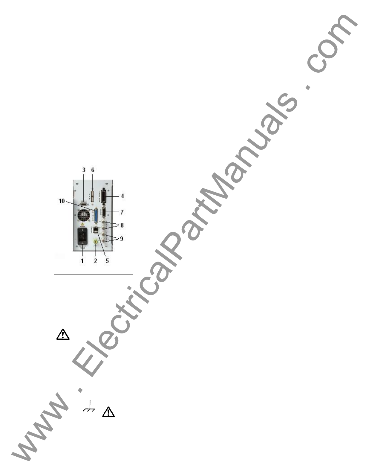
Figure 2 MPRT Rear Panel
1. Incoming Power / Line Cord – the input line cord, ground terminal, are mounted on the
back panel of the test set.
Input Line Cord
The test set is equipped with a line cord; see the accessory kit, which
connects to the male plug on the back panel. Verify the input voltage
before connecting the line cord to the power source.
NOTE: The unit can be powered from an input source with a rating of
100 VAC to 240 VAC. The unit automatically adjusts to the available
power if it is within the specified range.
2. Earth Ground Jack – use this terminal to connect chassis ground to earth ground.
A chassis ground (earth) point on the back panel is provided as an
additional safety ground.
12
Page 13

www . ElectricalPartManuals . com
3. RS-232C Serial Port - The serial port can operate at a maximum baud rate of 115,200
and will send / receive data in a serial fashion. See section 2.2.3.8 for more description.
4. IEEE-488 GPIB –The IEEE-488 GPIB port enables the unit to function as a talker-listener
as well as operate at speeds much faster than the serial bus, which will send / receive
data in a parallel fashion. This will allow DFR and EMTP files to be downloaded at a
faster rate. See section 2.2.3.9 for more description.
5. Ethernet 10BaseT – The Ethernet 10BaseT port will typically operate very efficiently and
effectively in real time. This port is the fastest communication method within this unit.
The setup will be similar to Microsoft
addition, this port provides the optimal method for downloading EMTP files, DFR
streaming, and updating the unit’s firmware as required. See sections 2.2.3.7 and 6.2 for
more descriptions.
6. USB Interface – Provides a communication port for connecting external devices, such as
the optional external binary input/output box to the unit (when more than 10 binary inputs
and/or more than 6 binary outputs are required).
7. EPOCH High Current Interface Port –The High Current Interface port is provided on the
rear panel of the unit. It is designed to interface with the Multi-Amp Models EPOCH-II or
EPOCH-20 High-Current Output Units (reference the EPOCH-20 or EPOCH-II Bulletins
for output specifications). This port interfaces with the optional interface module box to
provide control of up to three EPOCH-20 or EPOCH-II current amplitude, phase angle
and frequency outputs. Status of the EPOCH-20/II output can be seen on the TVI display.
8. External Clock –The external clock has separate input and output connections. The
Clock In is used in conjunction with a Clock Out from another unit or other clock source
for multiple unit operations or other special test applications. The Clock Out provides a
24 KHz clock signal to another unit that phase locks these units together.
9. External Trigger –The External Trigger has separate input and output connections. They
enable the unit to sync with another unit, or TTL (+ 5Vdc) signal source such as a GPS
satellite receiver. The Trigger In is used in conjunction with another unit to establish a
trigger for a special operation or programmed event. Typically the Trigger In
synchronizes to the Trigger Out unit and acts as a slave to it. The Trigger Out provides a
TTL digital signal to another unit in order to synchronize a multiple unit operation when it
needs to establish a trigger for a special operation or programmed event. The TTL signal
and pulse width for the GPS receiver is:
Voltage Input Signal: 3V peak minimum Pulse Width: 50µS nominal
10. PRINTER Interface Port– For future use (not used at this time).
®
Windows where one may set the protocol. In
Voltage/Current Modules (or V/I Gen). –There are four available slots for the Voltage/Current
Amplifier Modules. The slots are numbered from right to left with the back of the unit facing you.
Looking at the back of the unit, the rightmost slot equates to Phase A; the second slot from the
right equates to Phase B; the third slot from the right equates to Phase C; and left most slot may
be used to provide a fourth phase, polarizing voltage and/or current, residual voltage and/or
current, or other required sources.
13
Page 14
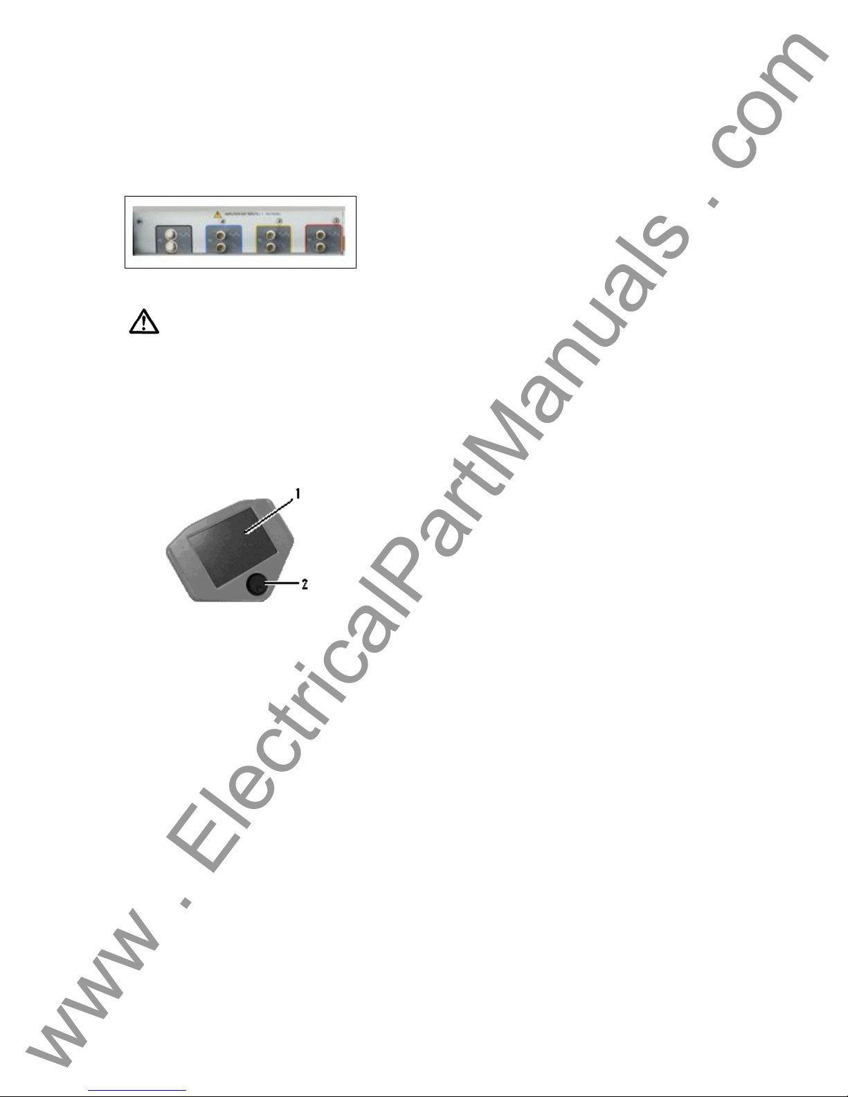
Amplifier EXT Inputs – There can be up to four sets of BNC connectors labeled V1/I5, I1; V2/I6,
www . ElectricalPartManuals . com
I2; V3/I7, I3 and V4/I8, I4 on the back panel depending on the number of amplifier modules
installed. These connectors are used to amplify an external analog signal using the MPRT
amplifiers. Application of ± 10 Volts Peak will provide Full Scale output from the selected output.
Figure 3 MPRT Rear Panel, Analog Input Terminals
CAUTION: DO NOT APPLY MORE THAN ± 10 VOLTS PEAK TO THE EXT INPUT
TERMINALS. APPLICATIION OF MORE THAN 10 VOLTS PEAK MAY DAMAGE THE
AMPLIFIER.
1.1.3 Touch View Interface
The Touch View Interface is used in manual operation of the unit. The color LCD touch-panel
display and control knob are the operator interface for the unit.
Figure 4 Touch-View Interface
1. LCD Color Display – this is an 8.5 inch touch panel display.
2. Control Knob – this knob will adjust values once the cursor is in the box location of the
value to be changed.
14
Page 15

www . ElectricalPartManuals . com
1.2 Terminology
The acronyms, terms, and definitions used throughout this manual are described below:
1.2.1 Acronyms
AC Alternating Current
AVTS Advanced Visual Test Software
CW Clockwise (rotation)
CCW Counter Clockwise (rotation)
DC Direct Current
GPIB General Purpose Interface Bus (IEEE-488)
GPS Global Position System
GUI Graphical User Interface
Hz Hertz
ID Identification
I/O Input/Output
kHz Kilo Hertz
LCD Liquid Crystal Display
LED Light Emitting Diode
MAG Magnitude
MHz Megahertz
MTA Maximum Torque Angle
NVRAM Non-volatile Random Access Memory
PC Personal Computer
ROM Read-Only Memory
RS-232 Serial Communication Interface
RTS Relay Test System
SRAM Static Random Access Memory
SSD Solid State Disk
TCM Timer Control Module
TVI Touch View Interface
USB Universal Serial Bus
VAC Volts Alternating Current
VDC Volts Direct Current
V/I Gen Voltage / Current Generator Module
VRMS Volts Root Mean Square
UUT Unit Under Test
1.2.2 Glossary of Terms
The MPRT TVI display screens prompt the user to select, or set, various values. The values vary
depending on the relay under test, and the relay setting screen. Many of the terms used are
similar in nature and mean virtually the same thing regardless of the type of relay. For example,
the term Time Dial is the used to define the time dial setting on the relay under test. The Time
Dial could be on an overcurrent relay, or just as easily be on a under voltage relay.
Unfortunately, some of the terms described here may apply to different types of relays in different
ways, and thus may not cover every possible relay made. However, it is hoped that this glossary
will help the user to understand every setting value on every relay setting screen.
1.2.2.1 Tap
A numerical value associated with a tap setting on the relay. Tap is normally associated with a
value of current, voltage, frequency or watts. Tap is used to define a setting value, pick up value,
or minimum operating point, of the relay under test.
15
Page 16

www . ElectricalPartManuals . com
1.2.2.2 Time Dial
A numerical value normally associated with a TIME CURVE, or defines the use of a specific time
curve from a family of curves. Used when conducting a timing test. The TIME DIAL number also
may be used in a Time-Curve algorithm in calculating the theoretical operating time of the relay
under test.
1.2.2.3 Instantaneous (Inst.) Tap
A numerical value associated with a tap setting on the instantaneous element of the relay.
Normally associated with a value of current or voltage. Used to define a pick up value, or
minimum operating point, of the instantaneous element of the relay under test.
1.2.2.4 Reset Time
Is a numerical value of time in seconds. Normally associated with electromechanical relays, this
is the amount of time required for the operating disk to reset. If multiple timing tests are
conducted on a relay, the test system will wait the Reset Time value prior to applying the next
timing test.
Note, if the Reset Time is too short, and the disk does not completely reset, then timing error
will be introduced to the test. Note that numerical relays also can have reset times to coordinate
with electromechanical relays.
1.2.2.5 Target Tap
Is a numerical value of dc current. This value is used when conducting the Target and Seal-in
tests on electromechanical relays.
1.2.2.6 Test Multiple
A numerical value normally associated with conducting timing tests. Multiples are normally
expressed in terms of 2, 3, 4, etc., times the Relay Tap, or Pickup, value of the relay under test.
If only one Test Multiple is entered, then only one timing test point will be conducted. If two or
three multiples are entered, then the test system will wait the Reset Time before applying the next
Test Multiple.
1.2.2.7 Reach
A numerical value expressed in Ohms. This value is used to determine the “distance”, in Ohms,
that the relay under test “sees” either into the transmission line or a generator.
1.2.2.8 Torque
A numerical value expressed in degrees. A value used in impedance relays to define the
“maximum torque angle” or “line angle” setting of the relay under test.
1.2.2.9 Operate, (Op) or Trip Time
A numerical value which expresses the operating time of the relay under test. Normally used to
specify a definite operating time for a given fault value.
16
Page 17

1.2.2.10 Winding (1,2,3,4) Tap
www . ElectricalPartManuals . com
A numerical value associated with the Winding Number i.e. 1, 2, 3, 4, etc., of a transformer
differential relay. Used to define the tap setting value and test for each winding.
1.2.2.11 % Slope
A numerical value which establishes the operating characteristic of a differential relay. The
operating characteristic of the differential relay is a line, with a slope defined by the ratio of the
operating and restraint values.
1.2.2.12 % Harmonic
A numerical value which establishes the percent of harmonic restraint for a harmonic restrained
transformer differential relay. This value will be used to determine Pass/Fail during the Harmonic
Restraint test.
1.3 Touch View Interface (TVI)
The Touch View Interface is the operator’s interface for the manual operation of this unit.
Variable or value changes are performed by the touch panel keypad or by rotating the control
knob after touching the display with your finger where the change is required. See section 2.2 for
operational details.
1.4 Input Power and Control
1.4.1 Input Power
The input voltage may be from 100 to 240 VAC, 50/60 hertz. Input current required varies with
the number of output modules in use and load. The maximum input power is 2100VA. The input
is protected by an ON/OFF switch / circuit breaker.
American power cord (part number 801046).
Model 84XX-XXXXEX comes with a Continental Europe power cord (part number 15021).
The 84XX-XXXXIX comes with a standard International Color code power co rd as shown below.
The cord, part number 14525, is ready for wiring to the appropriate plug (depending on country).
The following colors apply, Brown = Line, Blue = Neutral and Green/Yellow = Ground.
Model 84XX-XXXXAX comes with a North
Figure 5 International Color Coded Power Cord
1.4.2 Control Section
1.4.2.1 V/I Generator Module
The voltage and current ranges may be set to zero for automatic range adjustments or manually
set to the number desired in volts or amps as indicated below. The unit will choose the lowest
range which contains the desired value.
17
Page 18

www . ElectricalPartManuals . com
1.4.2.1.1 Voltage and Current Ranges
1.4.2.1.1.1 Model 8415 (each output module)
Voltage Range Power / Current (Max)
30.00V 150VA @ 5A
150.00V 150VA @ 1A
Current Range (RMS) Power / Voltage (Max)
4.0A 200VA @ 50.0 V
7.5A 200VA @ 26.7 V
15.0A 200VA @ 13.4 V
1.4.2.1.1.2 Model 8430 (each output module)
Voltage Range Power / Current (Max)
30.00V 150VA @ 5.0A
150.00V 150VA @ 1.0A
300.0V 150VA @ 0.5A
Current Range (RMS) Power / Voltage (Max)
4.0A 200VA@ 50.0 V
7.5A 200VA @ 26.6 V
15.0A 200VA @ 13.4 V
30.0A 200VA @ 6.67 V
1.4.2.1.2 Frequency Ranges
The output module is able to provide a variable frequency output with the following ranges:
DC
00.001 to 99.999
100.01 to 999.99
1.4.2.1.3 Phase Angle
The phase angle may be set from 0° to 359.9° in either lead or lag configuration, clockwise or
counterclockwise rotation. In addition, the user may select the angle display configuration of
±180°. See section 2.2.3.11, Phase Angle Setting, for information regarding Factory Default
settings.
1.5 Timer Control
The Timer can indicate the elapsed time either in seconds or in cycles. The Timer is prearranged
in the setup screens of the respective relay types that are to be evaluated. There are factory
default settings for the timer inputs.
RMS
RMS
RMS
RMS
RMS
RMS
RMS
18
Page 19

1.5.1 Binary Inputs – Timer
www . ElectricalPartManuals . com
The Timer is specifically designed to measure high speed operation of electro-mechanical, solidstate and microprocessor-based protection relays. In addition, it will perform timing tests on EHV
to low voltage breakers, trip circuits, and contactors. The factory default settings are:
Input 1: Timer start, normally open position, and latched ON
Input 2: Timer stop, normally open position, and latched ON
Input 3: Dry Contact monitor, normally open position, and latched OFF
And Inputs 4 through 16 as dry contact monitor, normally open position, and
latched OFF.
It incorporates the banana plug receptacles that may be programmed to be: Start Gates, Stop
Gates, and Monitor Gates, all Stop Gates, all Contact Continuity Monitors, or all Voltage
Applied/Removed Monitors.
1.5.1.1 Start, Stop, and Monitor Gates
In the TVI there are up to sixteen identical, independent, programmable gate circuits (Start, Stop,
and Monitor) that permit simple selection of the desired mode for timing or contact monitoring
operation. There are 10 internal inputs and 6 optional external inputs for the unit.
To monitor operation of the contacts or trip SCR in the device under test, an "ACTIVE" light is
provided for each gate. The gate circuit is isolated for voltage-sensing and can monitor solidstate logic signals. Each “Active” light will illuminate once contacts close or voltage is applied to
the gate. If desired, a tone generator (horn) may provide an audible indication when the contacts
close or voltage is applied.
1.5.1.1.1 Dry Contacts Open
Timer starts, stops or a continuity indicator goes out at the opening of normally closed contacts,
or when conduction through a semiconductor device, such as a triac or a transistor, is interrupted.
1.5.1.1.2 Dry Contacts Close
Timer starts, stops or a continuity indicator glows at the closing of the normally open contacts, or
upon conduction through a semiconductor device such as a triac or a transistor.
1.5.1.1.3 Application or Removal of AC or DC voltage
This will either start the Timer or stop the Timer. The continuity indicator will glow (application) or
darkens (removal) upon the application or removal of either an AC or DC voltage. A higher
threshold voltage helps to eliminate false triggers due to a noisy source. Lower thresholds allow
starting and stopping of timer from TTL voltage signals. The allowable voltage applied is 5 to 300
Volts AC or 5 to 300 Volts DC, current limiting resistors provide protection.
1.5.1.1.4 The Timer can be started when turning on any selected generator s.
1.5.1.1.5 The Timer can be started simultaneously with a change in Frequency, Phase
Angle, or Amplitude. Also, it can be started simultaneously with a Voltage or Current waveform
step.
1.5.1.1.6 The Timer can be stopped upon Phase Synchronization between two voltage
channels (normally used to time auto synchronizing relays).
19
Page 20

www . ElectricalPartManuals . com
1.5.2 Binary Outputs – Timer
There are 6 internal outputs and 10 optional external outputs for the unit. The contacts can
switch up to 300 VAC, 1 Amp or 250 VDC, 1 Amp continuous. The contacts may be to open or
closed, thus simulating circuit breaker operation. The programmable wait duration is from 1
millisecond to 10,000 milliseconds.
1.6 Battery Simulator
The receptacles provide 24, 48, 125, or 250 VDC with current limiting protection. The primary
application is to provide DC logic voltage to solid-state and microprocessor relays.
CAUTION:
NOTE: DC voltage is ON and available when the output is turned on using
the LCD touch panel or via software command. Do not plug or insert any
test lead into the BATTERY SIMULATOR binding posts without first
connecting the test leads to the load!
1.7 Transducer DC IN Measuring Circuit
The DC measuring circuit’s voltage is from 0 ±10VDC and current from either 0±1mADC or 1 to
±20mADC. This circuit is used for testing transducers. See Section 3.8.10.4 for more description.
1.8 Operation of Optional High Current Interface
The High Current Interface may be initiated in the Main Menu Screen. The High Current Interface
button is located at the bottom of the TVI. When initiated, the “High I” will change to “Unit I”.
When a relay test is completed and the HIGH CURRENT INTERFACE is no longer required, turn
OFF the EPOCH-20/II test unit.
2.0 SETUP
2.1 System
Unpack the unit and check for evidence of any shipping damage. If there is any visual damage,
notify the freight carrier to make a damage claim and notify Megger of the damage.
Potentially lethal voltages may be present on the output terminals. It is
highly recommended the operator read the user manual thoroughly and have an
understanding of the test set operation prior to turning power on.
1. Plug the Touch View Interface into the front of the unit. The TVI will be active once the
CAUTION
power is turned ON. A personal computer (PC) will take control of the unit if it is
connected. The unit power must be OFF before the PC is connected to the unit.
20
Page 21
2. Before connecting power to the unit, make sure the POWER ON/OFF Switch is in the
www . ElectricalPartManuals . com
OFF position (0). Plug the unit line cord into a power source and turn the POWER
ON/OFF Switch to ON (I).
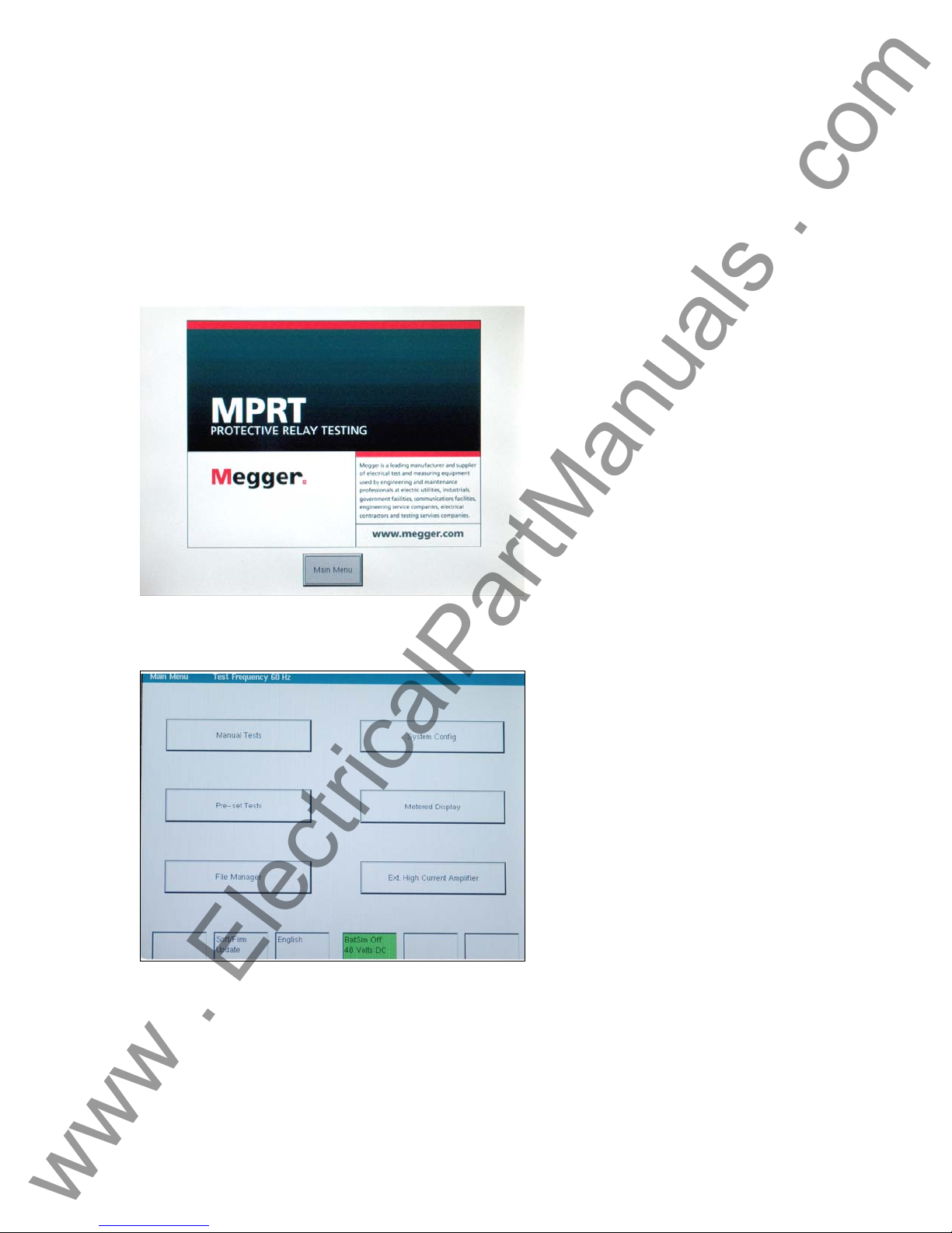
2.2 Touch View Interface Operation
The TVI is the manual control and user interface for the unit. All manual entries will be made
through the TVI unless the unit is connected to a personal computer. During the power up
sequence the test system automatically does self-test to insure everything is operating properly.
Once the system has completed its self checks the Introduction screen will appear.
Figure 6 Introduction Screen
Pressing the Main Menu button will produce the following screen.
Figure 7 Main Menu Screen
If a PC is connected, the TVI will display the monitored outputs when the PC is in control of the
unit. The Timer button will be available to select time ONLY. In addition, the vector graph will be
displayed on the TVI.
21
Page 22
2.2.1 Touch Panel Display
www . ElectricalPartManuals . com
The TVI Touch Panel Display is the means by which data is entered into the unit, while the unit is
in manual control. The TVI will display all active (ON) generators in red and all selected, but
inactive (OFF), generators in green. If a generator is not selected it will be grey. If an entered
value is out-of-range, an error screen will appear to notify the setting is out-of-range.
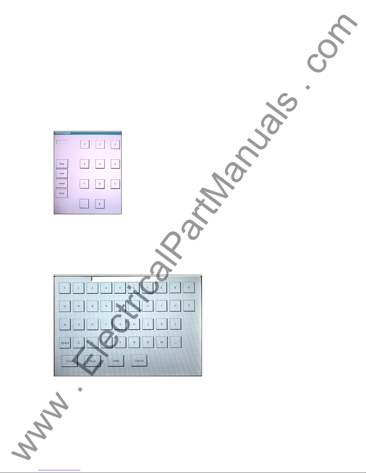
2.2.1.1 Keypad Entry
The keypad entry provides an interface to the user when entering a value in the various screens.
Touching a data entry window on the TVI will activate the Numeric Keypad. Pressing Enter or
Cancel will return the user to the previous screen that is in use. Pressing Ramp will select that
value to ramp when using the control knob. Pressing Clear will clear the value you just entered.
Figure 8 TVI Numeric Keypad
2.2.1.2 Alphanumeric Keypad
The alphanumeric keypad allows the entry of ASCII text into the TVI. This keypad is used to enter
file names in length for the primary name, and a 3 character extension in the file management
screen. This screen is also used when using the Transducer Test Setting Screen.
Figure 9 TVI Alphanumeric Keyboard
2.2.2 Control Knob
The control knob will change the values after touching the display to highlight the value that
requires ramping. Clockwise rotation increases and counterclockwise decreases. The control
22
Page 23
knob uses a speed control algorithm to provide fine adjustment, with a slow rotation, and a larger
www . ElectricalPartManuals . com
step adjustment with a faster rotation.
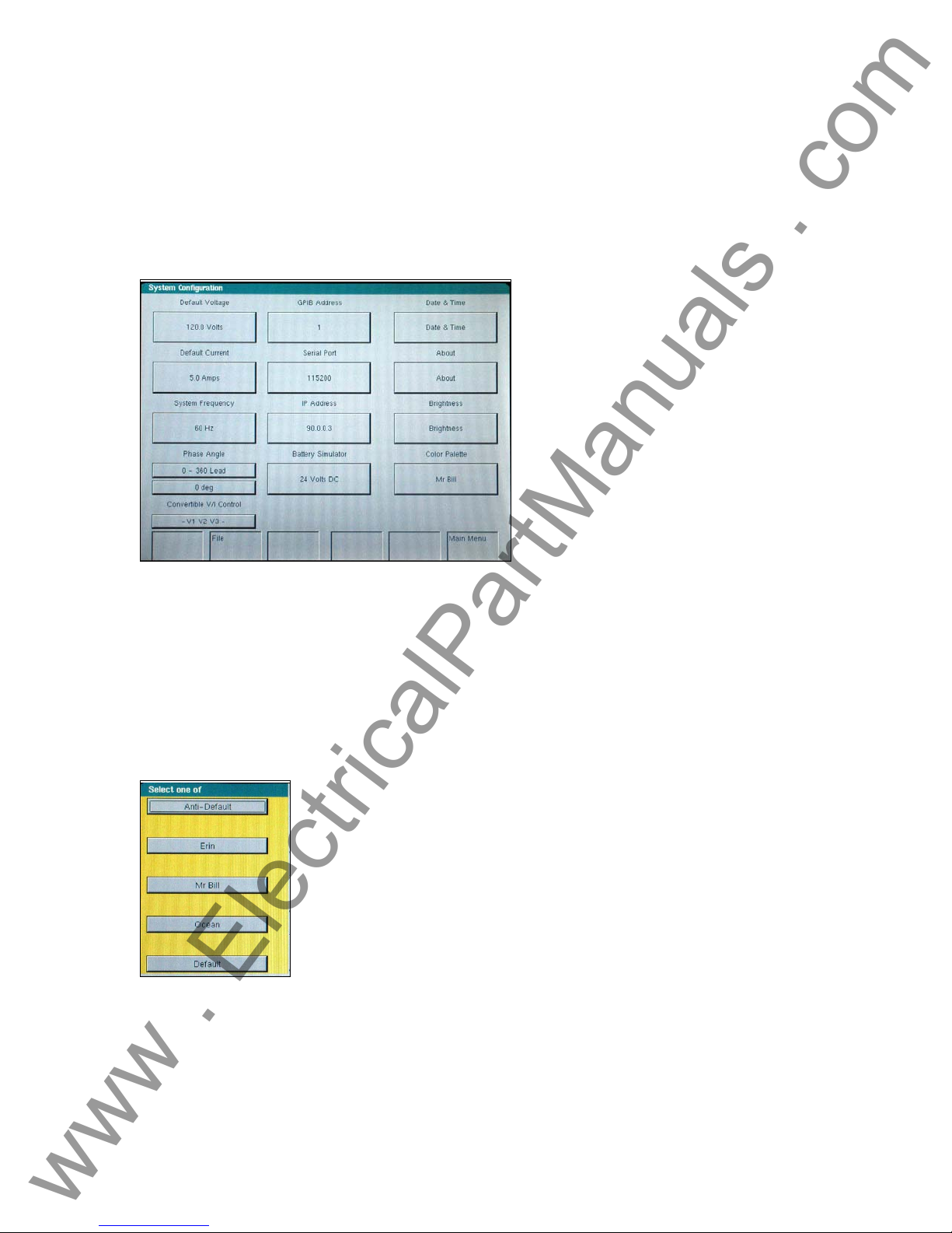
2.2.3 Factory Defaults
There are several factory default settings including language, system frequency, phase angle
rotation, battery simulator, GPIB address, IP address, brightness and contrast, unit and V/I Gen
serial numbers, and the color palette. Pressing the System Config. button on the Main Menu will
result in the following,
Figure 10 Default System Configuration Screen
2.2.3.1 Language
The factory default is English, but may be changed to French, Spanish, German, Italian, or
Portuguese. Other languages will be added to the list at a later date. To change language, press
the language select button on the Main Menu Screen, see Figure 7.
2.2.3.2 Color Palette
The background and color scheme is adjustable. Press the button to select from a variety of other
color schemes.
Figure 11 Color Palette Selection Screen
2.2.3.3 Brightness
The brightness is adjustable. The display will always be visible since hardware limits the
brightness from becoming too bright or too dark to be seen. Press the brightness + or - buttons to
make adjustments.
23
Page 24
2.2.3.4 About - Information Screen
www . ElectricalPartManuals . com
The V/I Generators, Timer and Unit Serial Numbers, software/firmware versions and unit
configuration will be displayed once the About button is pressed. This information is useful when
calling Dallas for service or technical support related issues.
2.2.3.5 Date and Time
Press this button to reset the Date and Time. This information is critical for saving tests and test
results in the unit internal file manager.
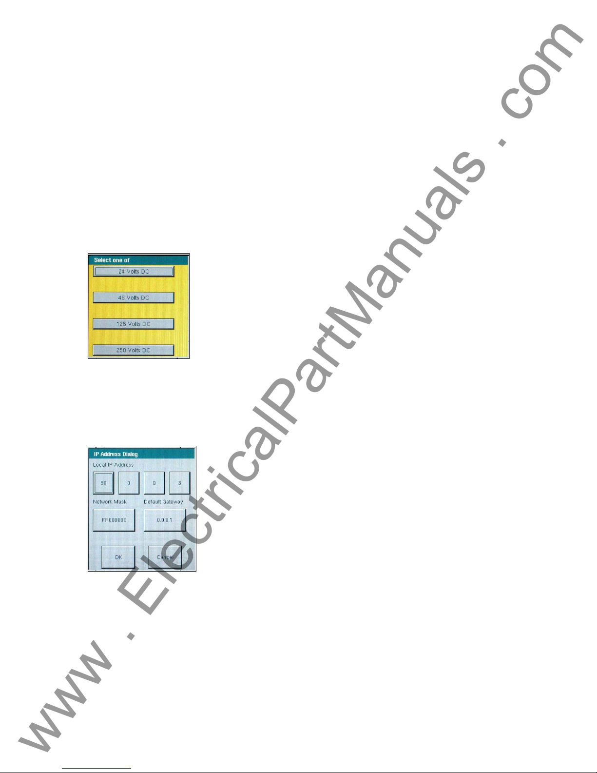
2.2.3.6 Battery Simulator Setting
The Battery Simulator output voltage can be set to 24, 48, 125, or 250 Volts DC. The Volts DC
selection only establishes the voltage values, but does not turn power ON for the Battery
Simulator. The various test setup screens will allow the Battery Simulator to be powered ON/OFF
as applicable. Pressing the DC Battery Simulator setting button the following selection screen will
appear.
Figure 12 Battery Simulator Voltage Selection Screen
2.2.3.7 IP Address
The IP address allows the unit to be connected and controlled on a local area network. Pressing
the IP Address button will produce the IP Address Dialog box. See Section 6.2 MPRT Ethernet
Port and IP Networks for details associated with use of the Ethernet port and IP address settings.
Figure 13 Ethernet IP Address Dialog Box
2.2.3.8 Serial Port
The Serial port will operate at various baud rates. Pressing the Baud Rate button will provide a
list of baud rates to choose from. Popular rates are 9600, 19200, 38400, 57600 and 115200. The
higher bauds rates provide faster downloads and response to commands.
24
Page 25
www . ElectricalPartManuals . com
2.2.3.9 GPIB Address
The GPIB address is selectable from 01 to 15. The factory default is 01. This will permit
communication between a personal computer and the unit once the IEEE-488 GPIB driver is set
to communicate with the respective address.
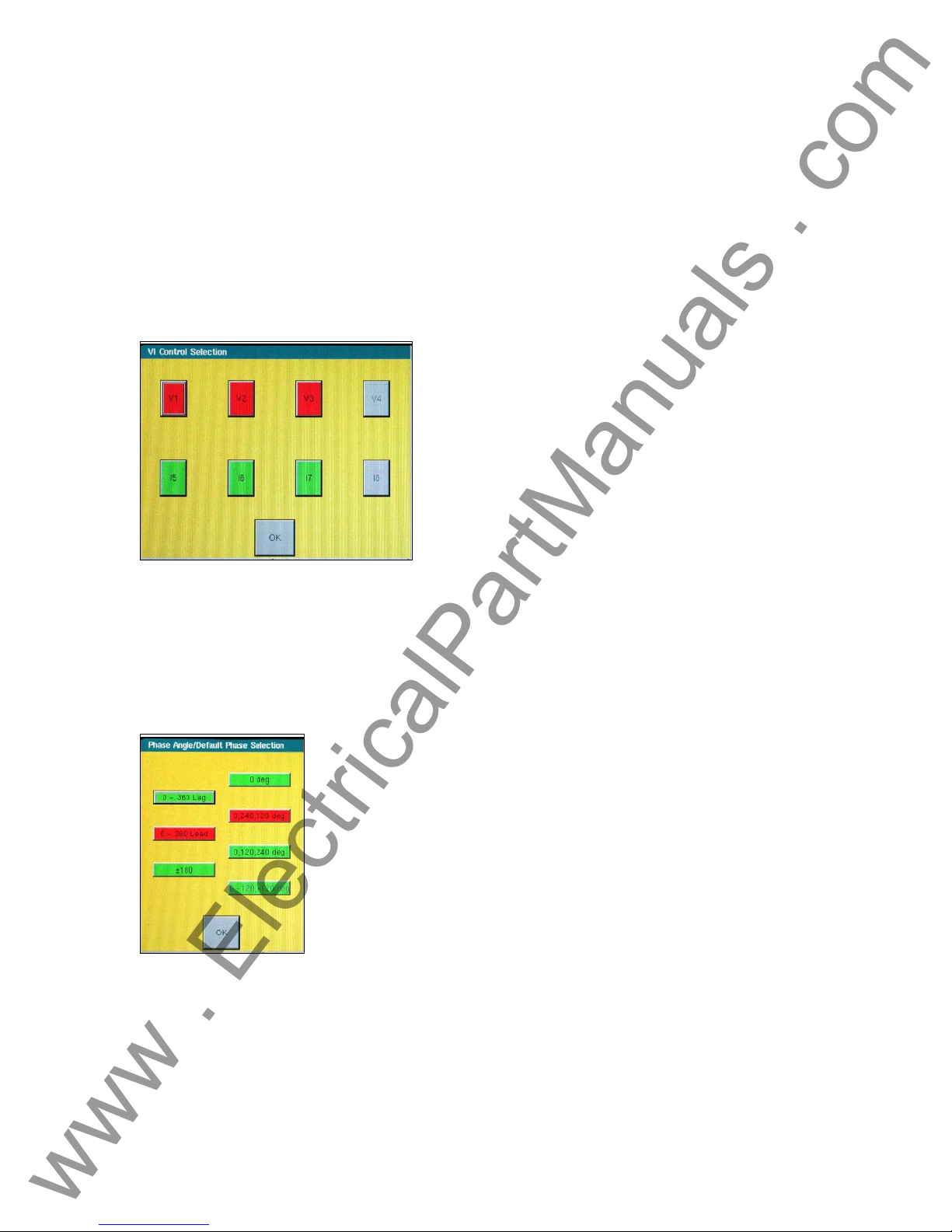
2.2.3.10 Convertible V/I Control
Used to change voltage channel to a current channel. Current configuration will be highlighted in
red, while the unselected channels will be in green. If the channel is not present, it will be in grey
and not available for selection.
Figure 14 Convertible V/I Selection Screen
Note: If channel is not installed, the channels will be grey (see Figure 15 above).
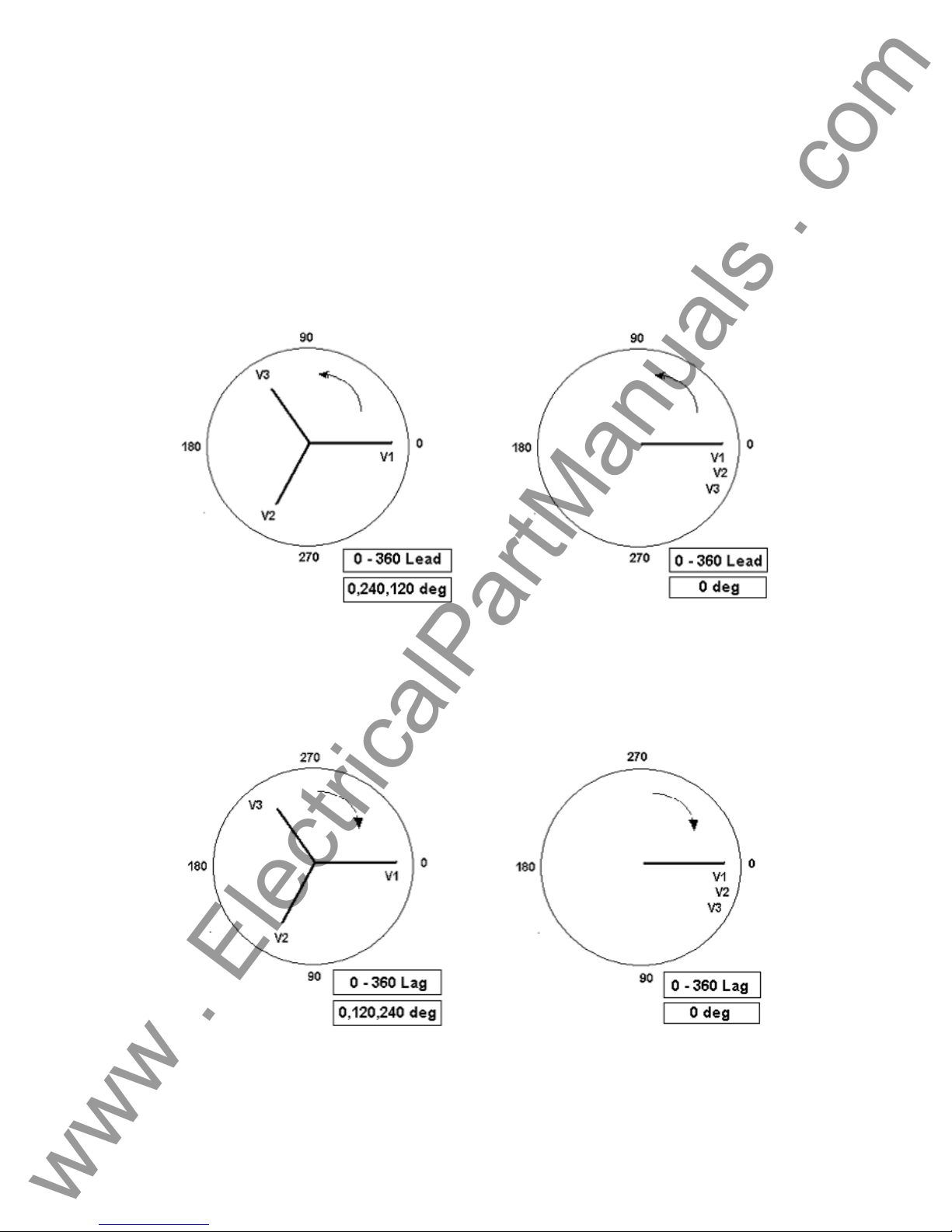
2.2.3.11 Phase Angle Setting
The Phase Angle Setting has three selections: 0-360° Lead, Lag or ±180°. In addition, the user
can set the display for clockwise and counterclockwise rotations. The factory default is 0-360°
lagging. Press the Phase Angle select button, and the following screen will appear.
Figure 15 Phase Angle Display Selection Screen
Select either Leading or Lagging and the phase indicators 0 deg., or 0, 240, 120 deg. or 0, 120,
240 deg. or 0, - 120, +120 deg. Selecting 0 -360 Lead and 0, 240, 120 deg. will result with V1
referenced at 0˚, V2 at 240˚ Leading V1 and V3 at 120˚ Leading V1, Counterclockwise rotation.
Currents when entered will Lead their respective voltages by the angle entered. Selecting 0 – 360
Lag, and 0, 120, 240 will result with the voltage V2 and V3 lagging V1 by 120 and 240 degrees
respectively. Any current values entered will lag their respective voltages by the angle indicated.
See section 3.2 for more details on setting phase angle relationships.
25
Page 26
www . ElectricalPartManuals . com
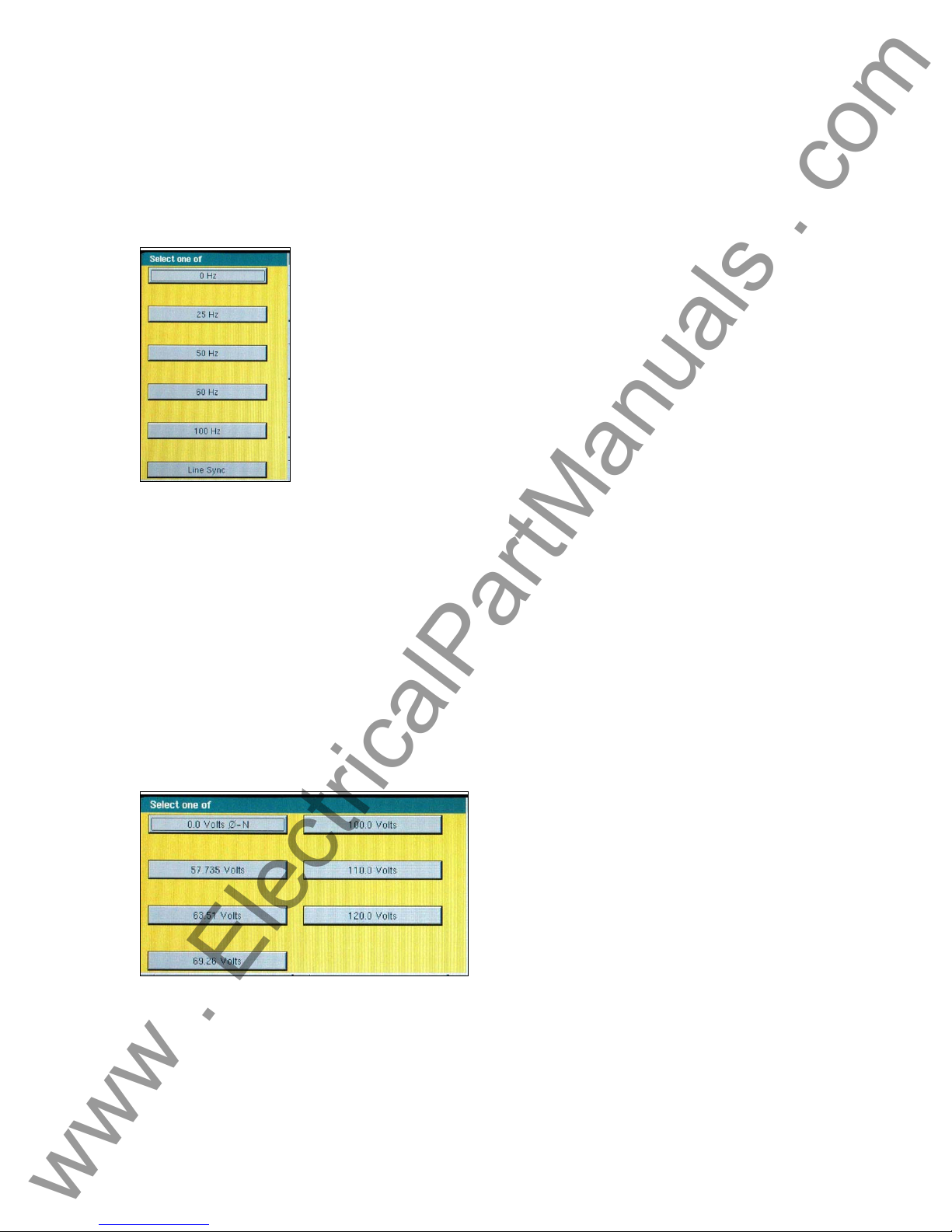
2.2.3.12 System Frequency
The system frequency will be set to the typical value of the country, either 50 or 60 hertz. Other
fixed frequencies are available. The unit can provide a fixed output frequency of 0 (DC), 25, 50,
60, 100 hertz, or Line Sync 50/60 Hz. To change the default frequency press the System
Frequency button and the following selection screen will appear.
Figure 16 System Default Frequency Select
2.2.3.13 Default Current Output
The Default Current provides a default value (set for 0 Amps) and provides the selectable setup
values for the current. The selectable currents are 0, 1, and 5 amps phase-to-neutral. This will
also be the value used in the prefault settings screen as well some other preset test screens.
These settings will change once the values are changed by the user in the relay settings screen.
2.2.3.14 Default Voltage Output
The Default Voltage output provides a default value (set for 0 volts) and provides the selectable
setup values for the voltage. These settings can be changed by the user in the relay settings
screen. Press the Default Voltage button and a list of popular phase-to-neutral values will be
provided to choose from. This is a big time saver when testing three-phase relays, the user does
not have to enter each individual voltage value, they will already be preset ready to use.
Figure 17 Default Voltage Setting Screen
26
Page 27
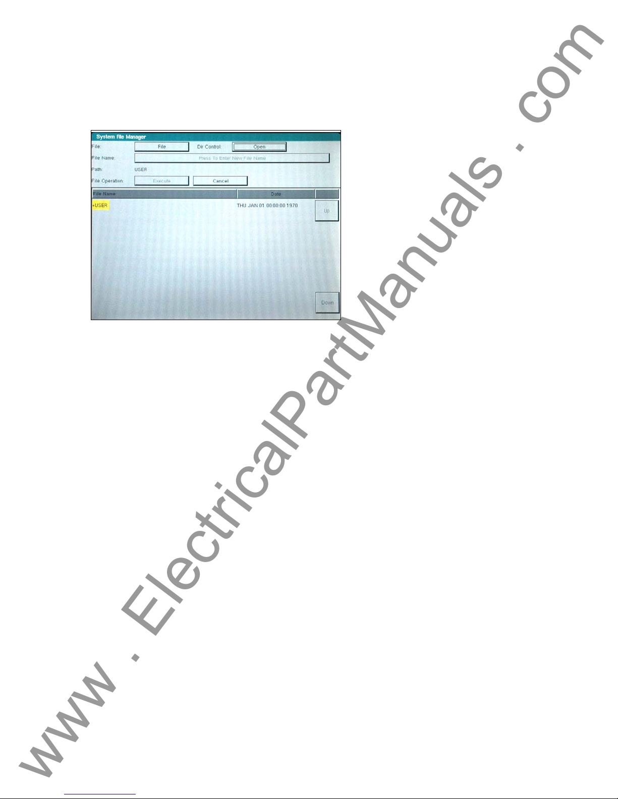
2.2.4 File Management
www . ElectricalPartManuals . com
The file management display is used by the TVI to access files stored on the unit’s internal
memory. This display will allow test files to be loaded, make or change directories, rename files
and directories, delete files and directories that were created by the customer.
Figure 18 File Manager Screen
The display is divided into two parts: the upper half is used to define the user action; and the
lower half displays the files and directories. File names are limited to 99 capital letter characters.
The alphanumeric keypad is used to enter file or directory names. In addition, the name of a file
or directory will appear in the name area as the cursor moves (using Up and Down buttons)
through the list of files or directories.
The following list of actions may be used in this display through pull down menus: Save Data,
Read Data, Make Directory, Rename, Delete, Save User Sys Defaults, Read User Sys Defaults,
Read Factory Defaults and Delete Factory Defaults. If files are to be deleted or written over, a
warning message will alert the operator this action is about to take place. This allows the
operator to cancel the action.
2.2.4.1 Test Files
The test files are used to verify the functionality of specific relays. These files typically verify the
functionality of the entire relay to ensure the operational readiness of this unit under test (UUT).
The test files may be provided by Megger or generated by the customer. Default files may be
added to or removed from the database. These files will reside in a specific directory in the
MPRT internal memory.
2.2.4.2 Test Results
The test results may be stored in the MPRT internal memory as a soft copy or downloaded into a
PC for soft and/or hard copy. The test results file must be saved using the file management
display. This is performed using a file naming convention that uniquely identifies the test results.
2.3 Communication Ports
There are several different communication ports. These ports are: Serial, USB, GPIB, Parallel,
and Ethernet. The function of these ports are similar, but are differentiated by their respective
speed at performing a set of operations.
27
Page 28

2.3.1 RS-232C Serial Port
www . ElectricalPartManuals . com
The Serial port will operate at various baud rates. The connection to it is limited by this speed.
Check baud rate using the System Configuration screen.
2.3.2 IEEE-488 GPIB
The IEEE-488 GPIB port will allow a faster baud rate and connectivity to the Unit. This port is
recommended for connection to the unit except when DFR streaming or EMTP files need to be
controlled in real-time.
2.3.3 Ethernet 10 BaseT
The Ethernet port will allow the fastest method for DFR playback streaming in real-time.
Firmware updates use this port for downloading purposes, since it is the most effective and
efficient communication. Simply connect the port to the networked PC and download accordingly.
2.3.4 USB Port
The USB ports are used for communication to external devices, such as an optional I/O interface
box.
2.3.5 Printer Port
The Printer port is for future use and is not available at this time.
2.4 Error Reporting
There are over 300 possible error messages that the operator may witness. Some have to do
with manual operation, some have to do with automated operation, and some have to do with unit
errors or overload situations. For example, errors will be reported when out-of-range values are
entered. The error screen will display the range for that value to ensure a value is entered that
resides within the tolerance of the range.
2.5 Advanced Visual Test Software (AVTS)
AVTS is external software specifically constructed to work with Megger relay test equipment
(MPRT and Pulsar). The software contains the necessary steps to perform specific relay tests. It
is designed to perform manual or automated relay testing for distance (impedance), over-current,
differential, frequency, voltage, synchronous, power and reclose relays. Also, AVTS is
specifically designed to perform DFR testing and playback including GPS synchronized end-toend tests. The MPRT comes with a Basic version of AVTS, while the Advanced and Professional
versions are optional.
3.0 OPERATING PROCEDURES
This section describes basic operating procedures for using the multiple output modules of the
unit for such applications as paralleling current outputs, conducting harmonic restraint tests,
series of potential sources to provide higher than rated potential, testing over/under voltage relays
and forming three phase voltage outputs.
3.1 Touch View Interface
The Touch View Interface (TVI) is used to operate the MPRT manually. It is controlled via a
touch screen and a control knob. The touch screen allows the operator to change a parameter by
simply touching the location for the value. Then, a keypad can be used to change the value or
the operator may use the knob to modify the value.
28
Page 29
3.2 Setting Phase Angle Relationships
www . ElectricalPartManuals . com
Think of each V/I Generator module as a vector generator. Each module has an internal zero
reference to which it references its phase angle settings as displayed on the TVI. This applies to
phase angle settings between the voltage and current outputs. When setting a phase angl e
between two outputs, it is recommended that one output be set at 0° and the other output be
referenced to the 0° . This is for operator convenience only. When setting an angle, the operator
has a multiple of choices, depending on the Default Phase Angle setting in the Default Setting
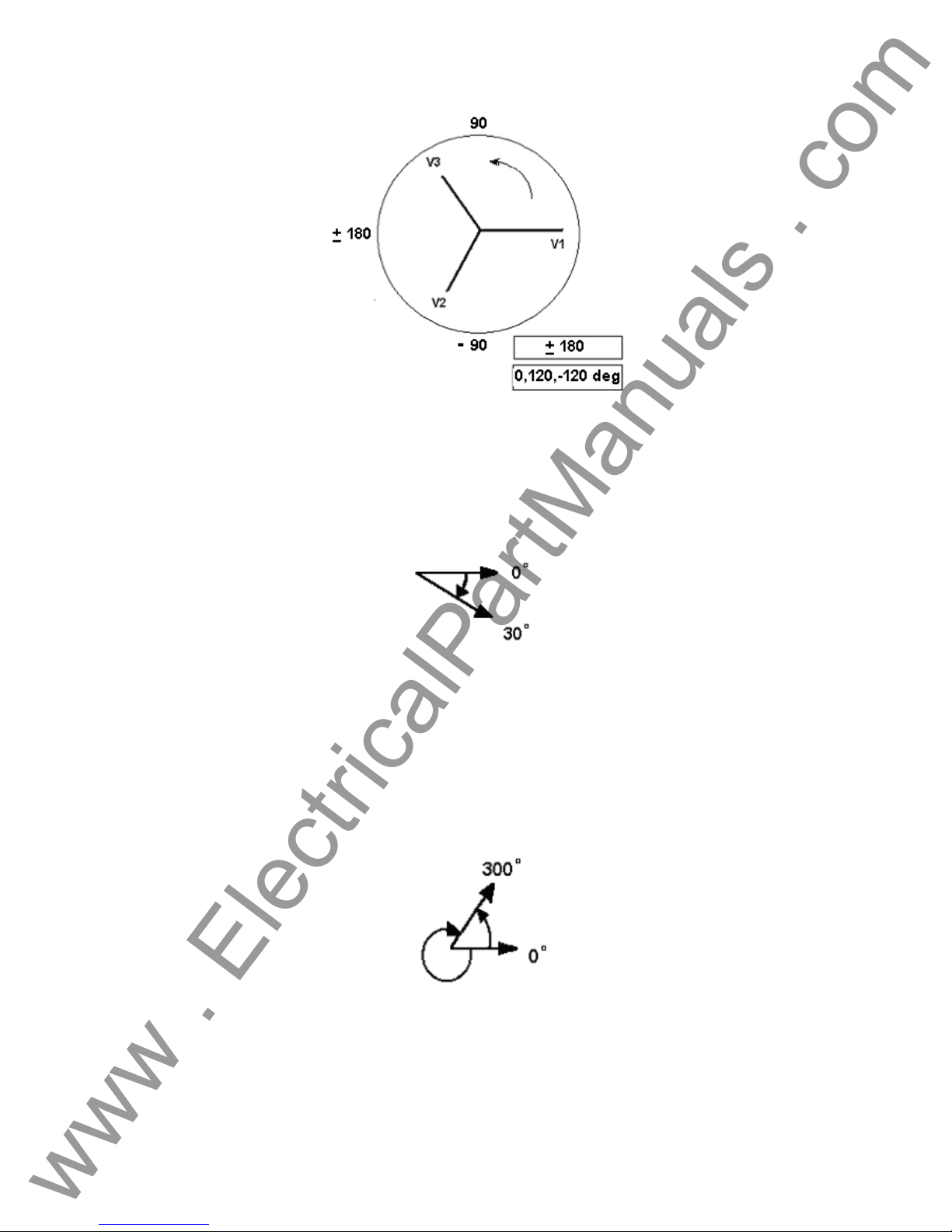
Screen, see 2.2.3.9. In the engineering world and in the following figures, the lagging diagram
displays negative rotation and will create negative sequence components, while the Lead and +/180 diagrams display positive rotation which is normal system activity.
Figure 19 Positive Phase Rotation Diagrams
Figure 20 Negative Sequence Phase Rotation Diagrams
29
Page 30
www . ElectricalPartManuals . com
Figure 21 Positive Phase Sequence Rotation Using ± 180˚
For example, using 0-360 Lag (0, 120, 240) setting an angle of 30° between the two outputs
would look like:
The reference output is 0° and the second output is rotated 30° clockwise. In other words, the
angle is lagging the referenced source by 30°.
Conversely, if the angle decreases in the counterclockwise direction from 359.9° toward 0.0°, for
a setting angle of 300.0°, the second output would look like:
The reference output is 0° and the second output is rotated to 60° in the counterclockwise
direction. In other words, the second output lags the reference output by 300° or leads it by 60°.
The user may default to phase angles to ±180° with the
- (negative) angles lagging and the +
30
Page 31

(positive) angles leading. Therefore, to set an angle of
www . ElectricalPartManuals . com
would be:
+ 10° leading, the vector relationship
3.3 Current Sources
3.3.1 Parallel Operation
Two, three or four current channels may be connected in parallel to provide additional current
capacity. This is necessary when higher test currents are needed for testing instantaneous trip
elements.
To parallel the current channels of the unit, perform the following:
1. Note that all units with a style number T in the 7
commons are grounded. Those units with a style number F the current commons are
floating. Using the current channel test leads, connect each
under test (both red and black terminals to the load). Obviously, for the floating common
units you have to connect the black common return to the relay or there would not be any
current flow from that channel. By connecting the commons together, all of the current
channels would then have a common reference point. For the grounded commo n return
units, there is an internal common ground between the current channels. By not
connecting a return lead to all of the current channels in use, part or all of the return
current will be forced through the internal ground. That means with a 4 channel unit up to
120 Amperes could be forced through the internal common ground. Because of size and
weight restrictions, the unit is protected internally against too high of a current through the
common ground using surface mounted fuse type elements. Blowing a ground fuse
element will require the unit be returned to the factory for repair! Therefore, it is important
that the parallel connections must be made at the relay, not at the source through the
common ground return. See the following figure.
th
digit (i.e. 8430L3T6A1) the current
current channel to the relay
Figure 22 Parallel of All Four Current Outputs
NOTE: All current channels should be set to the same phase angle.
31
Page 32

2. If two current channels that are to be used in parallel, set each to one-half of the output
www . ElectricalPartManuals . com
requirement. The settings between three current channels will be one-third the output
requirement, and four channels would be one-fourth. Initiate all current channels
simultaneously by pressing the Start button. All parallel current outputs must be ON to
prevent internal shunting of current. Note: If only two currents are to be used, only
connect two currents in parallel, etc. for three or four channels. In other words do not
parallel a current channel if you do not intend to use it.
3. All current channels have amplitude control now operates simultaneously to provide the
desired test current. Selecting Ramp of the current Magnitudes will allow the user to ramp
all currents at the same time using the Control Knob. Total output is the sum of the
current shown on the individual current channel amplitude displays.
3.3.2 Currents in Series Operation
Two current channels may be connected in series in order to double the available compliance
voltage. High impedance electromechanical ground overcurrent relays have always been difficult
to test at high multiples of tap due to the winding impedance and saturation characteristics. The
peak voltage required can exceed the maximum output voltage of one MPRT current output
channel, depending on the required test current. By connecting two current outputs in series, the
compliance voltage is doubled, providing higher test currents through the load. To series the
current channels of the unit, perform the following:
Using the current channel test leads, connect the Red output terminals of current channel to the
relay under test. For “floating” ground units connect the two black return terminals together as
shown in the following figure.
NOTE: One current channel should be set to 0 degrees and the other current channel
should be set to a phase angle of 180 degrees so that the two complian ce voltag es add across
the load. DO NOT attempt to series more than two currents together.
The two current channels that are to be used in series set each to the same test current
magnitude. Initiate the two current channels simultaneously by pressing the Start button.
All current channels have amplitude control now operates simultaneously to provide the de sired
test current. Selecting Ramp of the two current Magnitudes will allow the user to ramp the two
Figure 23 Series of Two Current Channels
32
Page 33

currents at the same time using the Control Knob. The test current is the current shown on either
π
π
www . ElectricalPartManuals . com
of the current channels amplitude displays.
3.3.3 Harmonic Restraint Test
One V/I Generator could be used to do differential or harmonic restraint tests when the voltage
channel is converted to a current source. This is useful when the unit only has one V/I Generator,
and if the required operating current doesn’t exceed 5 amperes and the restraint current doesn’t
exceed 15 amperes (Model MPRT 8415) or 30 amperes (Model MPRT 8430).
Two V/I Generator current channels may be used to obtain the desired current output to conduct
harmonic restraint tests on differential relays. One of the current channels provid es the second or
higher harmonic output and the other current channel provides the fundamental current.
There are two methods available to do harmonic restraint tests: the first method uses a pure
harmonic (2nd, 3rd, 5th, etc) of the fundamental from one current channel summed with the
fundamental current from a second current channel at the relay; The second method uses the
unit "HWAVE" feature. The HWAVE simulates the "diode method" recommended in some relay
manufacturers instruction literature. When the HWAVE is selected, the output module provides a
"half-wave" sinewave (similar to what you would see if using a diode in series with a current
source).
NOTE: Some recommended test procedures prefer using 4 DC amperes of half-wave. Since
the unit displays the full RMS sine-wave quantity, it will be necessary to set 8.89 amperes RMS
on the selected HWAVE current channel to achieve the desired equivalent of 4 DC amperes halfwave. Use the following formulas to calculate other values of DC half-wave:
)(
Ipeak
Irms
halfwaveIDC
Therefore,
halfwaveIdc =
Or
Irms =
414.1*
)(halfwaveIdc
414.1*Irms Ipeak and )( ==
45.0
Solving where:
4=Idc
4
89.8
== IrmsorIrms
45.0
33
Page 34

3.3.3.1 Basic Harmonic Restraint Test Procedure
www . ElectricalPartManuals . com
To set up the unit for harmonic restraint testing use the following procedure:
1. Select a current module to provide the desired harmonic. Set the current channel to the
desired harmonic. Use either second, third, or fifth harmonic in conjunction with the
selected frequency.
2. Connect the pair of current output leads from two of the unit’s current channels to the
relay under test so the current from each output is in parallel with one restraint and the
operating coil of the relay. Check to ensure both commons (grounds or earths) share the
same relay terminal.
3. Initiate the outputs. Increase the output to the appropriate harmonic current. It is
recommended that 1.0 ampere of harmonic current be set (it will make the math easier).
If using the HWAVE, set the displayed current to 8.89 amperes RMS (this equals 4
amperes DC half-wave).
4. Increase the fundamental current until the relay operates. To calculate the percent of
harmonic restraint use the appropriate equation below (if using pure harmonic current). If
using the HWAVE refer to the manufacturer’s instruction literature for the appropriate %
Harmonic Curve.
General Electric Type BDD
Harmonic+=
%
nd
(
Westinghouse / ABB Type HU
Harmonic+=
%
nd
(
NOTE: Restore the HWAVE channel to a sinewave upon test completion if the HWAVE
feature was used.
Current Harmonic 2
ndlfundamenta
Current Harmonic 2*2267.1
ndlfundamenta
100*
22
)Harmonic 2()
100*
22
)Harmonic 2()
34
Page 35

www . ElectricalPartManuals . com
3.4 Voltage Sources
3.4.1 Outputs Summed Together
Two voltage channels may be used to sum the voltage outputs to obtain higher than rated volt age
provided the load is ungrounded
Phase to 0° and set V
sum of the two voltage amplitudes, V
V2
Note that all units with a style number T in the 7th digit (i.e. 8430L3T6A1) the voltage
.
commons are grounded. For the grounded common return units, there is an internal common
ground between the voltage channels. Those units with a style number F the voltage commons
are floating. For the floating common units you have to connect the associated voltage channel s
black common returns together, when series operation is required. Remove external commons
when testing is completed. DO NOT attempt to series more than two voltage channels together.
3.4.2 Dynamic Voltage Relay Test
Over/Under Voltage Relays can be dynamically tested using one voltage channel along with the
timer. This procedure applies a "normal”" voltage to the relay under test, then automatically
adjusts the test voltage to a "fault" amplitude that is higher (over voltage) than the pickup voltage.
The same is true for testing under voltage relays except the test voltage is dropped below the
relay pickup voltage. Additionally, the timer is automatically started with "fault" voltage applied to
the relay under test.
First, set the "normal" voltage on the relay, then with the relay energized to normal condition, set
the desired "fault" voltage and Timer Start (relay trip circuit should be connected to the Timer
Stop terminals). If you want to de-energize the voltage to the relay when it trips, use the Auto-Off
feature. The Timer starts, the relay trips, and stops the Timer. It then removes power from the
outputs. See Voltage Relay in section 3.8.5.
3.4.3 3Ø, 3-Wire, Open-Delta and T-Connection
3.4.3.1 Open Delta
Two methods of obtaining a three-phase, three-wire voltage source are available. The Open-
Delta configuration, referenced in the following figure, is the easier to use when a balanced threephase source and it is required because the amplitude and phase relationship can be set directly.
No calculations are necessary.
When using the Open-Delta Configuration to set up a phase-to-phase fault, calculations’ using
the Law of Cosines is required to calculate amplitude and phase relationships. (See discussion
under T-Connection for simulating unbalanced, phase-to-pha se faults without need for
calculations.)
When using the Open-Delta configuration, it is suggested to use voltage channel #1, designated
, and voltage channel #2, designated V2, while the COMMON binding post is designated Vg.
V
1
With this arrangement, the magnitude and phase angle of the potentials can be easily calculated
and set. For the balanced three-phase condition V
Phase to 180°. The voltage outputs will add so the total voltage is the
2
. Connect the load between the voltage channel posts, set V1
and V2 as can be seen in the picture below.
1
•
V1
and V2g are equal in magnitude and
1g
35
Page 36

separated by an angle of 60
www . ElectricalPartManuals . com
magnitude, setting 0° on V
rotation is set to 360 Lag) on V
If V
3.4.3.1.1 Voltage Output Connections
When setting up an unbalanced Open-Delta configuration, the desired phase-to-phase fault
voltage, V
voltage V
Law of Cosines; where For any triangle the following formula applies:
is set using voltage channel #1 with its phase angle set to 0°. Phase-to-phase
1f
and its phase angle relationship for voltage channel #2, must be calculated using the
2f
o
. This is done by setting the V1 and Vg potentials equal in
and 300o (60 degrees leading assuming that the default phase
1
, (reference following figure).
2
Balanced 3θ - 3 Wire Fault Open Delta Connection
equals the desired test potential, then:
f
= Vf ∠ 0
Set V
Set V
1
= Vf ∠ 300
2
o
o
β
C B
The next figure shows the phase relationships between voltages and an example of the
necessary calculation. For convenience the amplitude and the phase angle settings for the
typical V
fault magnitudes are tabulated.
f
A
2
= AC2 + BC2 – 2 x AB x BC x cos ß.
AB
36
Page 37

www . ElectricalPartManuals . com
From the Law of Cosines
V
θ
arccos
12
)
(=
*
23
V2
V
2
V
23
V
V
V
At θ°
Lag
3.4.3.2 T Connection
The second method of obtaining a three-phase, three-wire voltage source is the so-called T-
Connection. The method, shown in the following figure, is easier to use when obtaining an
unbalanced, phase-to-phase fault simulation since it eliminates calculations. To reduce confusion
when using the T-Connection, the voltage output #1 is designated V
0°, voltage output #2 is designated V
designated V
or unbalanced phase-to-phase fault conditions can be easily simulated. The followin g figure
indicates these phase relationships.
NOTE: This method should not be used for very low fault voltages (i.e. 5 volts or less, or for
testing ABB or Westinghouse type SKD relays).
1 5 10 15 20 25 30 35 40 45 50 55 60 65 70
12
104 104 104 104 104 105 105 105 106 106 106 108 108 109 110
23
270 271 273 274 275 277 278 280 281 282 284 285 286 287 289
12
=(
)
2
= V
12
f
and its phase angle is set for 270 Any combination of balanced three phase faults
c
3
22
+(
*120
2
Settings For Typical Phase-to-Phase Fault Voltages
)
Figure 24 Open-Delta Unbalanced phase-to-phase Fault
Voltages
and its phase angle set for 180°, and voltage output #3 is
b
and its phase angle set at
a
37
Page 38

www . ElectricalPartManuals . com
Balanced or Unbalanced Fault T-Connection
= Desired Fault Voltage
V
f
1
=
V
af
1
=
V
V
2
=
cc
0∠°
V
2
V
fb
3
120 or V = 104V 270∠°
°∠180
2
38
Page 39

3.4.4 3Ø, 4-Wire, Y-Connection
www . ElectricalPartManuals . com
A three-phase, four-wire potential system can be provided using three output modules. The
vector relationships are referenced below. This Y-Connection has the advantage of being able to
supply a higher line-to-line voltage (1.73 x phase-to-neutral voltage). It is ideally suited for
simulating phase-to-ground faults. Voltage channel #1 is designated as V
relationship set for 0°. Voltage channel #2 is then designated as V
Finally, voltage channel #3 is designated V
clockwise rotation). V
respective test sets. If a neutral is required, it is connected to a ground post on any voltage
output module to ground the load.
, Vb and Vc are connected to the voltage potential binding posts on the
a
= Desired Fault Voltage
V
f
=
V
af
=
V
bf
=
V
cf
Balanced 3 θ, 4 Wire Y-Connection
and phase angle set for 240° (for a 1-2-3 counter
c
3
V 0∠°
3
3
V 120∠°
3
3
V 240∠°
3
and phase angle set for 120°.
b
with its phase
a
39
Page 40

www . ElectricalPartManuals . com
3.5 Internal Software Test Profiles
The test profiles are performed on the Relay Under Test to verify the relay is operating correctly.
The following describes the procedures to test a unit:
3.5.1 Pulse Ramping
The Pulse Ramping may be used to determine reach values for multi-zone relays, without
defeating the zone timer elements. The Pulse Time is set so that the test current is only on long
enough for the selected zone to operate. The following figure shows the current pulse generat ed
by the test unit.
Figure 25 Pulse Ramp
Select the fault type from the several available fault types: phase-to-ground; phase-to-phase; two
phases-to-ground; and three phase. Hold the voltage or the current constant. There are different
available pre-fault voltages to choose from. The user may enter a different value if desired. The
pre-fault current range is from 0 to 9.99 amps. The test starts with a pre-fault current (voltage) for
the Pre-fault Time Off delay to ensure the relay energizes (polarize) before starting the test. The
Pulse Time Off Delay Time is specified in milliseconds with the factory default value set at 1000
mSec (60 cycles at 60 Hz). The pulse ramping can begin once the relay is energized. The first
pulse has a selectable amplitude for the start value. This value is held for the defined Pulse Time
(in cycles). The generator output returns to the Pre-fault Value. The time the relay remains at this
level is determined by the Delay Time minus the Pulse Time. The next pulse is increased by the
increment value specified. The voltage magnitude and angle will be calculated for each of the
three phases when the test is complete. The current is calculated for the three phases. The
percent error is calculated for the Reach. The resistance is calculated for the final value. A fault
calculator, based on symmetrical components, is used to perform the fault calculations.
3.5.2 Ramping
The Ramping test maybe used to determine pickup values, verify single-zone impedance relays
or the outer most zone of a multi-zone impedance relays. For example, using the Ramping for
finding the reach of an impedance relay, select the fault type from a list. Determine whether the
voltage or the current is to be held constant. In the angle of torque calculation both the voltage
and current are held constant while the angle is ramping. Start with a pre-fault current (voltage)
for the Pre-fault Delay Time to ensure the relay is energized before the test begins. The Pre-fault
Delay Time has been specified in milliseconds and the factory default value is 1000 milliseconds
(60 cycles at 60 Hz). The ramping starts once the relay energizes. The generator output is set to
the start value specified. The generator holds the value for the specified Delay Time by the fault
40
Page 41

calculator or you may enter a specific value. Once the time has elapsed, the generator output
www . ElectricalPartManuals . com
increments by the Increment value specified in the fault calculator or by the entered value. The
ramping continues until pickup is detected or the Stop value is reached.
Overcurrent pickup ramp technique
When the test is complete, the voltage magnitude and angle, current, and Reach percent error
are calculated for the three phases. One of the inputs is setup to monitor the relay’s contacts.
When the first fault voltage is applied, the timer starts, and the relay stops when the relay trips.
3.5.3 Angle of Torque
The angle of torque test requires two phase ramps. The first ramp is performed by incrementing
the angle CW with the next ramp being incremented CCW. The test will use these two
measurements to calculate the angle of torque.
Measured CW
Torque
Z1
Calculated Angle
of Torque
Measured CCW
Torque
3.5.4 Step
The step test is similar to the pulse ramp except the Step test only uses a single pulse. The test
steps from a normal relay setup into the fault condition and waits for the relay to respond. The
test energizes the relay with the pre-fault values, sets the output of the generators to the fault
values, and then starts the timer. The timer input is used to monitor the relay’s trip. The timer
stops once the timer detects the relays contacts have operated. This function is normally used
when timing under/over voltage or frequency relays.
Angle of Torque
41
Page 42

3.5.5 Dynamic Frequency Hz/S
www . ElectricalPartManuals . com
Some frequency relays require a dual ramp to perform this test. Three sets of data need to be
established to perform the test. These sets of data are the pre-fault, fault, and post fault
conditions. The dynamic frequency test is executed from the Manual Frequency screen. This
test requires a single voltage generator. The change in frequency happens when the frequency
passes through the positive going zero-crossing. The rate of change is defined as the delta
(Hz/S). The frequency is changed every cycle at the positive going zero crossing. The test limits
the delta setting to a maximum value of 10Hz/sec with anything greater being treated as a Step
test. The frequency increment is calculated for each cycle prior to starting the dynamic ramp. If
we use a delta of 1 Hz/sec and want to ramp from 60 to 50 hertz, then the time would be ten
seconds to go from 60 hertz to 50 hertz in increments of 0.01667 hertz steps per cycle.
The first set defines the pre-fault values, which are necessary to energize the relay before the
fault condition. The following diagram shows the frequency decreasing. However, the frequency
ramp could be increasing as well. The pre-fault and fault values determines the direction of the
ramp. If the fault value is less than pre-fault value then the ramp is decreasing. If the fault value
is greater than the pre-fault value then the ramp is incremented up from the pre-fault value.
There isn’t any change to the generator outputs during pre-fault.
Hz
Prefault
60.00
Delta 1
Set point
Fault Freq
Post Fault
Delta 2
Prefault Time
Time
Duratio n
Dynamic Frequency
Duration is the time at the fault frequency. The dynamic fault requires the V/I Generators to ramp
to the actual fault value. Delta 1 is the fault ramp and the change in frequency divided by time
(Hz/S). The set point indicates the frequency when the relay first detects the fault. Once the set
point is reached the relay starts its timer. If the fault is not cleared within the timeout, the relay
will trip. The fault frequency is below the set point to ensure the relay trips for a decreasing ramp.
The fault value is greater than the set point for the increasing ramp. Once the ramp has reached
the set point, the timer is enabled. The fault condition is maintained for the time indicated in the
duration.
The post fault requires the V/I Generators to ramp with the generators in the fault condition. This
post fault ramp will ramp back to the pre-fault condition. The relay is also in a fault condition and
could trip. The post fault will be able to detect the relay trip and record the trip time. The post
fault timer will start at the beginning of the ramp and will not wait for the set point. Delta 2 is the
post fault ramp and is the change in frequency divided by time (Hz/S).
42
Page 43

3.5.6 Auto Synchronizing
www . ElectricalPartManuals . com
Two voltage output modules are required to perform tests on synchronizing type relays. To
perform Pick-Up or Closing Angle tests, voltage channel one, V
allow the second voltage channel, V
Remember the phase angle indicated on V
characteristic is 20° leading, set an angle of 340° on voltage channel 2.
, to provide the variable phase angle adjustment.
2
will be a lagging angle. If the relay’s closing
2
0
V1
, will be referenced at 0° and
1
Breaker Contacts Close
Increase P h a se of V2
Relay Contacts Close
+90
Auto Synchronizing Relay
3.5.7 Pickup
The pickup test performs a Ramp or Pulse Ramp (see 3.5.1 for description of Pulse Ramp).
Using the Ramp function, the relay is first energized using two times the Tap or Pickup value.
After the relay contacts close, the outputs are set to 90% of the Pickup value. The output is
increased until the relay trips. Once the relay trips the test stops and the output is recorded.
V2
-90
180
Pickup Test
43
Page 44

3.5.8 Seal-In (Target)
www . ElectricalPartManuals . com
The Seal-In test is performed using DC output current. An AC output current may be applied on
over-current relays to close the trip contacts. Some relays require the user to block the trip
contacts closed to perform this test. The test ramps the DC output at a pre-selected rate see
Test Configuration. The Seal-In test requires the user to press the Stop button, when the Seal-In
contact is closed, since these contacts cannot be monitored by the unit.
3.5.9 Timing
The Timing test is similar to the pulse ramp except is uses a single step. The test steps from a
normal operating condition into the fault condition and waits for the relay to respond. The test
may energize the relay with the normal operating values, then sets the output of the generators to
the fault values, and starts the timer. The timer input monitors the relay constants. The fault
value is a multiple of relay tap settings. This value could be 70%, 80%, 90%, 200%, 300% or
400% depending on the type of relay being tested (voltage or current). The test has three
multiple values and uses each of them until a trip occurs or the last value is used. In some tests,
the user may select IEEE / IEC time curves. Trip times are calculated using preprogrammed
timing formulas per IEEE or IEC standards. However, if IEEE / IEC times curve are not used, or
specific value/trip time tests are to be preformed, the user may manually enter a value(s) and
associated trip time(s) in the appropriate value windows.
3.5.10 Harmonic Restraint
This test uses two current generators. The generators are in phase while the current is being
ramped. The two currents are set to different frequencies. The starting current is determined by
the value entered. With the harmonic current preset (i.e. 1 ampere) the second current channel
(fundamental) will be increased at the preset ramp rate, until the relay trips or the max value is
reached.
3.5.11 Slope
This test uses two current generators. The starting current is determined by the value entered.
The current on one V/I Generator starts at the selected value and is labeled the operate
generator. It starts at (I2 x % Slope x 0.9). The restraint current is set as I2. The operate current
will be increased at the preset ramp rate, until the relay trips or the max value is reached
3.5.12 Through Fault
This test uses two current generators in parallel. The test is executed and the output current is
applied to the relay. The test monitors the relay contact to determine if it is open or closed.
3.5.13 Polarizing
This test uses all three current generators where the output current for each generator is
paralleled at the relay. The test is executed and the output current is applied to the relay. This
test does not monitor any contacts, but does step the generator outputs to the current value
selected. The duration is selected with a maximum time of four cycles to ensure no damage
occurs.
44
Page 45

3.6 Timer
www . ElectricalPartManuals . com
Due to the timer complexities on the MPRT there are two timer screens. There is a basic timer
control screen and the complex timer control screen. When the user presses the Timer Setup
button anywhere in the TVI the user will be first presented with the basic timer setup screen. This
screen will provide the user with the capability to setup the timer for nearly all relay testing
requirements. If the basic timer setup screen does not provide all the capability required the user
can press the Complex Timer Setup button. This screen will provide the user the capability of
adjusting all the timer input and output setting parameters.
Basic Timer Setup Menu
Figure 26 Basic Timer Setup Menu
Description
Controls
Contact: The Contact label identifies which input terminal the
associated controls are referring to.
Action The Action control determines the action of the timer.
The selections are as follows:
Mon(C) Monitor Contact will light the front panel
indicator conditions become true.
Mon(V) Monitor Voltage will light the front panel
indicator when the conditions become true.
Start Starts the timer and lights the front
panel indicator when the conditions become true.
Stop Stops the timer and lights the front panel
indicator when the conditions become true.
CA Starts the timer when current starts to
be generated.
45
Page 46

Condition Sets the parameters under which a true or false contact
www . ElectricalPartManuals . com
is determined. The selections of condition are as
follows:
NO Normally Open dry contact.
NC Normally Closed dry contact.
VA Voltage Applied wet contact.
VR Voltage Removed wet contact.
N/A Not Applicable.
Latch Mode: Sets the parameter under which the timer will either stay
on after a contact state becomes true or will return to
previous state after the contact changes state.
Latch On: Will latch the timer in that condition after the
timer has reached a true condition.
Latch Off: Will allow the timer to return to original
condition even after the contact has reached a true
condition.
Max Operate Time Determines the maximum timer the unit will operate
before the outputs are turned off. This function is only
applicable when the timer is operating.
Debounce Time Determines how long a contact must be in a true state
before the condition is determined to be true.
Turn Currents Off (Stop Contact Only) When selected will turn all output currents off when the
stop contact becomes true.
Turn Voltages Off (Stop Contact Only) When selected will turn all output voltages off when the
stop contact becomes true.
Horn On / Horn Off This selection will turn the horn on when any contact is
determined to be true
Seconds / Cycles This selection will toggle the timer between measuring in
seconds or cycles.
Complex Timer This selection will display the Complex Timer Setup
menu.
Timer Reset This selection will reset the timer to zero.
Back. This selection will return the user to the screen
previously displayed.
46
Page 47

Complex Timer Setup Menu
www . ElectricalPartManuals . com
Description
Figure 27 Complex Timer Setup and Binary Output Screen
Up to 16 different timers are available using the button labeled T1. This button will present a pull
down menu to select the required timers.
This screen will be used by the default screen to set system defaults. The time selection, when
used from the default screen, will set the time base for all screens. If seconds are selected, all
screens will set Duration, Op. Time, and Pulse Time to indicate seconds or milliseconds, as
applicable. If cycles are selected, the time base will be set to cycles. When this display is called
from a setup screen, the time base for the timer in that screen may be changed.
3.7 Battery Simulator
There are two distinct buttons for the Battery Simulator: the Volts DC and value settings. The
Battery Simulator output voltage can be set to 24, 48, 125, or 250 volts DC with the factory
default set at 125 VDC. This establishes the voltage values, but does not turn the Battery
Simulator power ON. The various test setup screens will allow the Battery Simulator to be
powered ON, as applicable.
3.8 Relay Testing
The Touch View Interface contains three user interfaces in one unit, a color LCD alphanumeric
display panel, a control knob, and a touch panel used to input data into the unit. The TVI will
display all active generator settings in red and all inactive, generator OFF, settings in green. If an
entered value is out of range, the display will be yellow and an Error Screen will appear. The
control knob will change the contents after the value is highlighted by touching the display with
your finger.
NOTE: The unit contains factory default values to run a quick test without entering data.
However, a one-time warning message will notify the user the test is being conducted with factory
default values if the defaults are used.
47
Page 48

www . ElectricalPartManuals . com
3.8.1 Touch View Interface Graphical User Interface
3.8.1.1 Main Menu Screen
The main screen is used to access the four normal operating modes and an optional external
high current amplifier connection, if this option is purchased.
Figure 28 Main Menu Screen
The Manual test screen performs all testing manually.
The Pre-set test screen option provides a variety of preset relay specific test routines.
The File Manager allows access to the stored data files.
The System Config. button allows changes to the system and screen defaults.
The Metered Display allows the viewing of the actual output and input values, as measured by
the unit’s hardware.
The optional External High Current Amplifier connects to an external source such as an EPOCH
II, EPOCH 20, or other system.
48
Page 49

3.8.1.2 Pre-Set Test Menu
www . ElectricalPartManuals . com
The Pre-set menu contains all the relay test options.
Figure 29 Pre-Set Test Menu
Select the relay type to undergo testing. Once selected, the display will move to that set of relay
setting and test screens.
The File button takes the user to the File Management Screen
The Main Menu button will return to the Main Screen.
49
Page 50

3.8.2 Impedance Relay Testing Menu
www . ElectricalPartManuals . com
The unit contains a set of default values so a test operator interested in running a quick test will
not have to enter this data.
Figure 30 Impedance Relay Menu Screen
This menu permits the setting and testing of an Impedance or Distance relay. These tests should
be conducted in accordance with the manufacturers relay specifications.
The bottom of the screen has common buttons.
File: This selection will take the user to the File
Manager.
Pre-set Tests Menu: This selection will return the controller to the
Pre-set Test Menu Screen.
Main Menu: This selection will return the controller to the
Main Menu:
50
Page 51

3.8.2.1 Impedance Relay Setting Screen
www . ElectricalPartManuals . com
Figure 31 Impedance Relay Setting Screen
The relay setting screen sets the relay values to test the impedance or distance relay. The
settings determine if the relay passed or failed when the test completes.
• The Reach setting value is in Ohms with a range of 0.000 to 99.99 ohms. The factory default
is 10 ohms.
• There are two parts to defining the torque setting: lag or lead. A lagging torque uses a range
of 0-360°, and the lead/lag torque has a range of –180° to +180°. The torque angle value
has a range of 0.0 to 999.9. The default value will be set at 75° with current lagging voltage.
The user will only be able to enter a value of ± 180° if the ± 180° range is selected.
• The Operating Time is the time in milliseconds with a range of 0 to 9999 milliseconds. The
factory default value is 100 milliseconds.
• The Zone button is used to select the test label. The unit tests a single zone at one time and
has the information for that zone. The factory default is Zone 1 (Z1). The zone is used
during the save operation to separate test data for each zone to save data for all zones in a
single file. The Zones are Z1, Z2, Z3, Z4, Z5, Z2R, Z3R, Z4R, and Z5R.
• The Target Tap has selectable values with a factory default of 0.2 DC amperes.
• Select either Single-Phase, Three-Phase Y or Three Phase Open Delta modes with the
factory default set to Three-Phase Y. However, selecting the single-phase mode limits the
user to one V/I Generator.
The bottom of the screen has common buttons.
Test Menu: This selection will return the controller to the
Test Menu Screen.
Main Menu: This selection will return the controller to the
Main Menu:
51
Page 52

www . ElectricalPartManuals . com
3.8.2.2 The Reach Test Setting Screen
The impedance test settings screen will establish and run a test using factory defaults or
manufacturer’s recommended values, if entered.
Figure 32 Reach Test Setting Screen
• The Pre-fault Settings button sets the necessary pre-fault conditions for relay testing.
• The Relay Settings button will allow the entry of relay setting values to test and evaluate the
relay.
• When the current lags the voltage using 0° to 359.9°, the message “lagging xxx.x
used. Otherwise, no message is required when using ±180°.
• The Fault Type determines the kind of fault tested. The accepted values are AG, BG, CG,
AB, BC, CA and ABC (Note: A, B, and C are the phases and G is ground).
• The test entry has two possible selections: Ramp and Pulse Ramp. The selection of the
Ramp test will not use all the entries for pulse time. The ramp test changes the V/I Generator
output without re-applying the pre-fault conditions. Pulse Ramp uses all screen values.
• The Pulse Time is the length of time the fault value will be applied. The range is from 1to
9999 cycles.
• The Delay Time is the cumulative of fault and fault recovery times with a range of 1 to 9999
cycles.
• The channel selection default condition enables all Voltage and Current Generators. This is
indicated by a check mark in each of the generators selection area.
• The voltage or current may be held. If Voltage is held the Start, Stop, and Increment values
will need to be expressed in Amps. If Current is held the Start, Stop and Increment values
will need to be expressed in Volts. The Increment value is used to increase the fault values
from the start to stop. The Start value is the beginning value for the output ramp. The limit for
the MPRT 8415 unit is 15 amps RMS. The limit for the MPRT 8430 unit is 30 amps RMS.
The Stop value is the upper limit of the ramp. The two values should be checked to ensure
the Stop value is greater than the Start value if ramping current up.
Note: The Pulse Time must be less than Delay Time.
Degree” is
52
Page 53

www . ElectricalPartManuals . com
The bottom of the screen has common buttons.
File: This selection will take the user to the File
Manager.
Batt Sim Off / Batt Sim On: This selection will turn the Battery Simulator On
and Off.
Test Menu: This selection will return the controller to the
Test Menu Screen.
Main Menu: This selection will return the controller to the
Main Menu:
Start / Stop: This selection will apply the set quantities
displayed and begin the test. After Start is
pressed this button will turn red and display
Stop. Pressing Stop at any time will stop the
test and turn the outputs off.
3.8.2.3 Impedance Relay Pre-fault Setting Screen
This screen sets the relay values before fault values are applied to ensure the relay is properly
energized.
Figure 33 Pre-Fault Setting Screen
• The voltage range is 0.00 to 150.0 volts. This value may be set to two decimal places (i.e.
69.28) with a pull down menu that provide values of 57.735, 63.51, 69.28, 110.0 and 120.0
volts.
• The voltage can be set phase-to-neutral (φ-N) or phase-to-phase (φ-φ) with a factory default
voltage of 69.28 φ-N.
• The current range is 0.00 to 9.99 amps with the factory default setting of 3.00 amps.
• There are two parts to defining the angle. The first part is set in the System Default Screen
where the angle entry is defined as leading or lagging. Lagging value range is 0° to 360°,
53
Page 54

and the lead/lag value range is –180° to +180°. The factory default is set to 75° lagging. The
www . ElectricalPartManuals . com
second part is the value with a range of 0.0 to 999.9. If the user selects ±180° range the user
will only be able to enter a value of ±180°.
• The time entry determines how long the relay will stay in the pre-fault state and the range is
0.0 to 999.9 milliseconds. The factory default is 100.0 milliseconds.
The bottom of the screen has common buttons.
Test Menu: This selection will return the controller to the
Test Menu Screen.
Main Menu: This selection will return the controller to the
Main Menu:
Apply: This button will set and apply the pre-fault
values.
3.8.2.4 Impedance Relay Reach Test Result Screen
This screen displays the test results. The Zone and Fault values are copied from the setting
screen while all other values are calculated from the test results. The results of the test will be
displayed as “Test Passed” or “Test Failed”. No data may be entered in this screen.
Figure 34 Reach Test Screen
The bottom of the screen has common buttons.
File: This selection will take the user to the File
Manager.
54
Page 55

Batt Sim Off / Batt Sim On: This selection will turn the Battery Simulator On
www . ElectricalPartManuals . com
and Off.
Test Menu: This selection will return the controller to the
Test Menu Screen.
Main Menu: This selection will return the controller to the
Main Menu:
Start / Stop: This selection will apply the set quantities
displayed and begin the test. After Start is
pressed this button will turn red and display
Stop. Pressing Stop at any time will stop the
test and turn the outputs off.
3.8.2.5 Impedance Relay Test Timing Settings
This screen sets the values to perform the relay timing test.
Figure 35 Impedance Timing Test Setting Screen
• The Pre-fault Settings button will move to its screen and will allow changes to the relay
specifications. If factory defaults are used, a one-time warning message should be displayed
to notify the factory default values are being used.
• The Relay Settings button will move to its screen and allows changes to the relay
specifications.
• The Timer Setup screen will define how the timer will be used.
• The Fault type button determines the fault the test will perform. The accepted values are AG,
BG, CG, AB, BC, CA and ABC (Note: A, B, and C are the phases and G is ground).
• The voltage and current generators may be enabled or disabled. The default condition ha s all
voltage and current generators enabled. This is indicated by a check mark in the cha nnels
selection boxes. If the Voltage is held the Stop value is expressed in Amps. If the Current is
held the Stop value is expressed in Volts. The V/I Generators used in the MPRT- 8415 unit
have 15 amps / 150 volts RMS limit and the MPRT - 8430 unit have 30 Amps / 300 volts
RMS limit. The Stop value is the fault value for the test.
55
Page 56

• The timing test jumps from the pre-fault value to the fault value and times how long the relay
www . ElectricalPartManuals . com
takes to trip.
• The Run Test button is used to execute the current test setup.
The bottom of the screen has common buttons.
File: This selection will take the user to the File
Manager.
Batt Sim Off / Batt Sim On: This selection will turn the Battery Simulator On
and Off.
Test Menu: This selection will return the controller to the
Test Menu Screen.
Main Menu: This selection will return the controller to the
Main Menu:
Start / Stop: This selection will apply the set quantities
displayed and begin the test. After Start is
pressed this button will turn red and display
Stop. Pressing Stop at any time will stop the
test and turn the outputs off.
3.8.2.6 Impedance Relay Timing Test Result Screen
Figure 36 Impedance Timing Test Setting Screen
This screen displays the results upon test completion. The Zone and Fault valu es are copied
from the setting screen while all other values are calculated from the test results.
56
Page 57

The bottom of the screen has common buttons.
www . ElectricalPartManuals . com
File: This selection will take the user to the File
Manager.
Batt Sim Off / Batt Sim On: This selection will turn the Battery Simulator On
and Off.
Test Menu: This selection will return the controller to the
Test Menu Screen.
Main Menu: This selection will return the controller to the
Main Menu:
Start / Stop: This selection will apply the set quantities
displayed and begin the test. After Start is
pressed this button will turn red and display
Stop. Pressing Stop at any time will stop the
test and turn the outputs off.
57
Page 58

3.8.2.7 Impedance Relay Angle of Torque Test Settings Screen
www . ElectricalPartManuals . com
The angle of torque settings screen allows the operator to input the values necessary to perform
the relay angle of torque test.
Figure 37 Angle of Torque Setting Screen
• The Pre-fault Settings button will change screens and will allow changes to meet the
manufacturer specifications. If the factory defaults are used, a one-time warning message
should be displayed to notify default values are being used.
• The Relay Settings button will change screens and will allow changes to meet the
manufacturer’s specifications.
• The Timer Setup screen allows the user to define how the time will be used.
• The Fault Type determines the fault the test will perform. The accepted values are AG, BG,
CG, AB, BC, CA and ABC (Note: A, B, and C are the phases and G is ground).
• The voltage and current generators may be enabled or disabled. The default condition ha s all
voltage and current generators enabled. This is indicated by a check mark in the cha nnels
selection boxes. If the Voltage is held constant, the Stop value is expressed in Amps. If the
Current is held constant, the Stop value is expressed in Volts. The V/I Generators used in
the MPRT-8415 unit have 15 amps / 150 volts RMS limit and the MPRT-8430 unit have 30
Amps / 300 volts RMS limit. The Stop value is the fault value for the test.
• The Start test button is used to execute the current test setup.
• The Start, Stop and Increment values will need to be expressed as an angle in degrees. The
Increment value is used to increase the angle values from the start to the stop value. The
test needs to be performed in two directions to calculate the torque. During one test the stop
value will function as the end point. When the test is performed in the other direction the stop
value will be the starting point.
The bottom of the screen has common buttons.
File: This selection will take the user to the File
Manager.
Batt Sim Off / Batt Sim On: This selection will turn the Battery Simulator On
and Off.
58
Page 59

Test Menu: This selection will return the controller to the
www . ElectricalPartManuals . com
Test Menu Screen.
Main Menu: This selection will return the controller to the
Main Menu:
Start / Stop: This selection will apply the set quantities
displayed and begin the test. After Start is
pressed this button will turn red and display
Stop. Pressing Stop at any time will stop the
test and turn the outputs off.
3.8.2.8 Impedance Relay Angle of Torque Test Results Screen
This screen displays the results upon test completion. The Zone and Fault valu es are copied
from the setting screen while all other values are calculated from the test results. The results of
the test will be displayed as “Test Passed” or “Test Failed”. No data may be entered in this
screen.
Figure 38 Angle of Torque Test Screen
The bottom of the screen has common buttons.
File: This selection will take the user to the File
Batt Sim Off / Batt Sim On: This selection will turn the Battery Simulator On
Test Menu: This selection will return the controller to the
Main Menu: This selection will return the controller to the
Manager.
and Off.
Test Menu Screen.
Main Menu:
59
Page 60

Start / Stop: This selection will apply the set quantities
www . ElectricalPartManuals . com
displayed and begin the test. After Start is
pressed this button will turn red and display
Stop. Pressing Stop at any time will stop the
test and turn the outputs off.
60
Page 61

3.8.2.9 Impedance Relay Target & Seal-In Test and Results
www . ElectricalPartManuals . com
This screen displays the results upon test completion. The results of the test will be displayed as
“Test Passed” or “Test Failed”. No data may be entered in this screen.
Figure 39 Impedance Target and Seal-in Test Screen
The bottom of the screen has common buttons.
File: This selection will take the user to the File
Manager.
Batt Sim Off / Batt Sim On: This selection will turn the Battery Simulator On
and Off.
Test Menu: This selection will return the controller to the
Test Menu Screen.
Main Menu: This selection will return the controller to the
Main Menu:
Start / Stop: This selection will apply the set quantities
displayed and begin the test. After Start is
pressed this button will turn red and display
Stop. Pressing Stop at any time will stop the
test and turn the outputs off.
61
Page 62

3.8.3 Overcurrent Relay Test Menu
www . ElectricalPartManuals . com
This menu permits the setting and testing of an Overcurrent relay. These tests should be
conducted in accordance with the manufacturers relay specifications. There are two different
curve types: IEEE/ANSI and IEC which are user selectable on the various screens.
Figure 40 Overcurrent Relay Test Menu Screen
These tests should be conducted in accordance with the manufacturers relay specifications.
The bottom of the screen has common buttons.
File: This selection will take the user to the File
Manager.
Pre-set Test Menu: This selection will return the controller to the
Pre-set Test Menu Screen.
Main Menu: This selection will return the controller to the
Main Menu:
62
Page 63

3.8.3.1 Over-Current Relay Setting Screen
www . ElectricalPartManuals . com
Figure 41 Overcurrent Relay Setting Screen
• The Timing button will change screens and will allow changes to meet the manufacturer
specifications.
• The Instantaneous button will change screens and will allow changes to meet t he
manufacturer’s specifications.
• The Target & Seal-In button will change screens and will allow changes to meet the
manufacturer’s specifications.
• The Pickup button will change screens and will allow changes to meet the manufacturer’s
specifications.
• Relay Tap, Time Dial, Instantaneous Tap, Reset Time, Target Tap, IEEE/IEC curve type, and
test multiple(s) need to be set unless factory defaults are used.
Figure 42 IEEE Time Curve Selection Menu
Once the multipliers are selected the expected (theoretical) trip times are displayed according to
the curve type ,curve shape and time dial selected previously.
User defined trip times can be typed into Theo Trip Time Multiples A,B,C fields if the relay does
not have an IEEE/ANSI or IEC standard curve.
63
Page 64

www . ElectricalPartManuals . com
3.8.3.2 Overcurrent Relay Test Configuration Screen
The test configuration menu is used to adjust the advanced relay testing parameters. The TVI
has default test parameters that should not need to be adjusted by the user. If the user has
determined these values do need to be adjusted, then following the directions in the TVI
Operations section.
Figure 43 Test Configuration Screen
Pickup Ramp Specifications
Increment % / 10 cycles This value is used to control the how fast the
MPRT will increase the current to determine the
pickup value. The value input into this field is in
% increase per 10 cycles. The default value for
this field is .02 % of pickup. Example: If the
pickup value requires 1.0 ampere the MPRT will
increase the current magnitude 0.0002 amperes
every 10 cycles until the relay operates. For
larger increments, use a larger percentage.
Instantaneous Pulse Ramp Specifications
Increment ( %) This value is used to control the how fast the
MPRT will increase the current to determine the
Instantaneous pickup value. The value input into
this field is in % increase per pulse. The default
value for this field is .02 % of pickup. Example:
If the pickup value requires 10 amperes the
MPRT will increase the current magnitude 0.002
amperes for the Pulse Time On value until the
64
Page 65

relay operates. For larger increments, use a
www . ElectricalPartManuals . com
larger percentage.
Pulse Time On (cyc) This value is used to control how long the output
pulse is on during an Instantaneous pickup test.
This value is in cycles. Note: Set Pulse Time On
slightly greater than the operating time of the
relay.
Pulse Time Off (cyc) This value is used to control how long the output
pulse is off during an Instantaneous pickup test.
This feature is required in order to protect the
relay under test against excessive heating due
to applying large currents continuously. This
value is in cycles. Note: Start with equal
amounts of Pulse Time On and Off.
Target & Seal-In Ramp Specifications
Increment % / 100msec This value is used to control the how fast the
MPRT will increase the current to determine the
pickup value for the target and seal-in. The
value input into this field is in % increase per
100msec. The default value for this field is .02
% of pickup. Example: If the pickup is set for 2.0
amperes the MPRT will increase the current
magnitude 0.0004 amperes every 100msec until
the relay seal-in contacts close.
Relay Settings The Relay Settings button will return the user to
the Relay Settings Menu.
The bottom of the screen has common buttons.
File: This selection will take the user to the File
Manager.
Test Menu: This selection will return the controller to the
Test Menu Screen.
Main Menu: This selection will return the controller to the
Main Menu:
65
Page 66

www . ElectricalPartManuals . com
3.8.3.3 Overcurrent Relay Pickup Test Results
This screen displays the results upon test completion. No data may be entered in this screen.
Figure 44 Overcurrent Relay Pickup Test Screen
The Timing, Instantaneous, and Target & Seal-In test screens may be entered to change test
settings.
The bottom of the screen has common buttons.
File: This selection will take the user to the File
Manager.
Batt Sim Off / Batt Sim On: This selection will turn the Battery Simulator On
and Off.
Test Menu: This selection will return the controller to the
Test Menu Screen.
Main Menu: This selection will return the controller to the
Main Menu:
Start / Stop: This selection will apply the set quantities
displayed and begin the test. After Start is
pressed this button will turn red and display
Stop. Pressing Stop at any time will stop the
test and turn the outputs off.
A timer setup link is available on this screen. Also the Timer Setup configuration is displayed for
convenience. The status of the relay contact will be displayed on the screen real time along with
the value of the current. The Stop current is the maximum current provided by the test set before
66
Page 67

test is stopped. This instance is applicable if the relay does not operate when ramping the current
www . ElectricalPartManuals . com
up between the Start and Stop values. After the test is completed, the current amplitude will be
read out from the screen or stored in the memory.
3.8.3.4 Overcurrent Relay Target & Seal-In Test Results
This screen displays the results upon test completion. No data may be entered in this screen.
Figure 45 Overcurrent Relay Seal-in Test Screen
The Timing, Instantaneous, and Pickup test screens may be entered to change test settings.
The bottom of the screen has common buttons.
File: This selection will take the user to the File
Manager.
Batt Sim Off / Batt Sim On: This selection will turn the Battery Simulator On
and Off.
Test Menu: This selection will return the controller to the
Test Menu Screen.
Main Menu: This selection will return the controller to the
Main Menu:
Start / Stop: This selection will apply the set quantities
displayed and begin the test. After Start is
pressed this button will turn red and display
Stop. Pressing Stop at any time will stop the
test and turn the outputs off.
When running this test, a current (I
main contact. Once the contact closes, the path for the DC target and Seal-in closes also. Current
is used to ramp a DC current up until the target drops. The user must press the Stop button and
I
5
record the results.
=2xTap) will be applied first to the relay in order to close the
1
67
Page 68

3.8.3.5 Overcurrent Relay Instantaneous Test Results
www . ElectricalPartManuals . com
This screen displays the results upon test completion. No data may be entered in this screen.
Figure 46 Overcurrent Relay Instantaneous Test Screen
The Timing, Target & Seal-In, and Pickup test screens may be entered to change test settings.
Each current channel must be selected by touching I1, I2, and I3. However, there must be a
corresponding V/I Generator.
The bottom of the screen has common buttons.
File: This selection will take the user to the File
Manager.
Batt Sim Off / Batt Sim On: This selection will turn the Battery Simulator On
and Off.
Test Menu: This selection will return the controller to the
Test Menu Screen.
Main Menu: This selection will return the controller to the
Main Menu
Start / Stop: This selection will apply the set quantities
displayed and begin the test. After Start is
pressed this button will turn red and display
Stop. Pressing Stop at any time will stop the
test and turn the outputs off.
A link to Timer Setup configuration is be available on this screen. Also the Timer Setup
configuration is displayed for convenience. The user selects the appropriate number of channels
required pressing I
selected current channels. The status of the relay contact will be displayed on the screen real
time along with the value of the current(s) and the percentage error.
and I3.The amount of current required will be split proportionally between
1,I2
68
Page 69

3.8.3.6 Overcurrent Relay Timing Test Results
www . ElectricalPartManuals . com
This screen displays the results upon test completion. No data may be entered in this screen.
Figure 47 Overcurrent Timing Test Screen
The Instantaneous, Target & Seal-In, and Pickup test screens may be entered to change test
settings.
The bottom of the screen has common buttons.
File: This selection will take the user to the File
Manager.
Batt Sim Off / Batt Sim On: This selection will turn the Battery Simulator On
and Off.
Test Menu: This selection will return the controller to the
Test Menu Screen.
Main Menu: This selection will return the controller to the
Main Menu:
Start / Stop: This selection will apply the set quantities
displayed and begin the test. After Start is
pressed this button will turn red and display
Stop. Pressing Stop at any time will stop the
test and turn the outputs off.
A link to Timer Setup configuration is be available on this screen. Also the Timer
69
Page 70

Setup configuration is displayed for convenience. The user selects the app ropriate number of
www . ElectricalPartManuals . com
channels required pressing I
between selected current channels. After the test is completed the trip time for all multipliers, the
percentage error and current(s) amplitude will be read out from the screen or stored in the
memory as can be seen in the figure below:
and I3.The amount of current required will be split proportionally
1,I2
Figure 48 Overcurrent Timing Test Result Screen
3.8.4 Differential Relay Test Menu
This menu permits the setting and testing of a differential relay. These tests should be conducted
in accordance with the manufacturers relay specifications.
Figure 49 Differential Relay Test Menu Screen
There are several options to further define the tests to be performed. Selecting one of these
options will present the test setup screen for that option.
Part 710000
Rev 3 Date 11/15/2005
Page 71

www . ElectricalPartManuals . com
The bottom of the screen has common buttons.
File: This selection will take the user to the File
Manager.
Pre-set Test Menu: This selection will return the controller to the
Pre-set Test Menu Screen.
Main Menu: This selection will return the controller to the
Main Menu:
3.8.4.1 Differential Relay Setting Screen
Figure 50 Differential Relay Setting Screen
The Differential setting screen requires some values to be entered or verified before performing
the test. The factory defaults may be used to test a relay generically.
The following is a description of the buttons of the Relay Settings screen:
Winding # Tap The user enters the tap value for each of the relay windings. Default
value is 5.0 Amperes.
Min. Pickup % Tap The user enters the relay minimum percentage of tap where the relay will
operate. Default 30 %. Therefore, with a tap value of 5 amperes, the
minimum pickup value for the relay on any tap would be 1.5 Amperes
(30% of tap).
% Harmonic The user enters the % of harmonic restraint the relay is set to. The
default value is 20 %.
71
Page 72

Order of Harmonic The user enters the order of harmonic restraint that the relay is set for.
www . ElectricalPartManuals . com
For example, a second harmonic restraint would be set to 2, third
harmonic 3 and fifth harmonic 5. The default value is 2.
% Slope Enter the % slope of the relay. For example, a 30 % slope , enter value
30. The default value is 25.
Restraint I Enter the desired restraint current that will be used in the slope test. The
default value is 10 Amperes.
Relay Type Selection is either electromechanical or solid state. If solid state is
entered , the user will be required to press the stop button when the relay
LED lights up upon pickup.
Polarizing I Some electromechanical relays require a polarizing current be applied
prior to conducting pickup tests. Enter the desired polarizing current. The
default value is 50 Amperes.
Through Fault I This will be the current applied in the through fault test. Consult relay
manufacturer literature for appropriate test current value. Default value is
20 Amperes.
Target Tap The Target Tap has selectable values with a factory default of 0.2 DC
amperes.
Relay Model Cal. The Westinghouse HU relay requires a different calculation for harmonic
restraint. If testing an HU select HU, the default is All Other.
Inst. Tap Enter the instantaneous trip current value. The default value is 40
Amperes.
Test Configuration This will take the user to a new screen. It was added to simplify the
Relay Settings screen. The Test Configuration Screen provides
additional input parameters for more complex tests, and for adjusting
ramping and pulse ramping values.
The bottom of the screen has common buttons.
File: This selection will take the user to the File
Test Menu: This selection will return the controller to the
Main Menu: This selection will return the controller to the
Test Configuration The Test Configuration button will take the user
Manager.
Test Menu Screen.
Main Menu:
to the Test Configuration Menu. This menu is
used to set additional test parameters such as
ramp increment and start and stop points.
These test parameters should not need to be
adjusted.
72
Page 73

www . ElectricalPartManuals . com
3.8.4.1 Differential Relay Test Configuration Screen
The test configuration menu is used to adjust the advanced relay testing parameters. The TVI
has default test parameters that should not need to be adjusted by the user. If the user has
determined these values do need to be adjusted, then following the directions in the TVI
Operations section.
Figure 51 Test Configuration Screen
Pickup Ramp Specifications
Increment % / 10 cycles This value is used to control the how fast the
MPRT will increase the current to determine the
pickup value. The value input into this field is in
% increase per 10 cycles. The default value for
this field is 1 % of pickup. Example: If the
pickup value requires 1.0 ampere the MPRT will
increase the current magnitude 0.01 amperes
every 10 cycles until the relay contacts close.
For smaller increments, use a smaller
percentage.
Instantaneous Pulse Ramp Specifications
Increment % This value is used to control the how fast the
MPRT will increase the current to determine the
Instantaneous pickup value. The value input into
this field is in % increase per pulse. The default
value for this field is 1 % of pickup. Example: If
the pickup value requires 10 amperes the MPRT
will increase the current magnitude 0.1 amperes
for the Pulse Time On value until the relay
contacts close. For smaller increments, use a
smaller percentage.
73
Page 74

www . ElectricalPartManuals . com
Pulse Time On (cyc) This value is used to control how long the output
pulse is on during an Instantaneous pickup test.
This value is in cycles.
Pulsar Time Off (cyc) This value is used to control how long the output
pulse is off during an Instantaneous pickup test.
This value is in cycles.
Target & Seal-In Ramp Specifications
Increment % / 100 msec This value is used to control the how fast the
MPRT will increase the current to determine the
pickup value for the target and seal-in. The
value input into this field is in % increase per
100 msec. The default value for this field is 1 %
of pickup. Example: If the pickup is set for 2.0
amperes the MPRT will increase the current
magnitude 0.02 amperes every 100 msec until
the relay seal-in contacts close.
Relay Settings The Relay Settings button will return the user to
the Relay Settings Menu.
74
Page 75

3.8.4.2 Differential Relay Winding 1, 2 or 3 Pick-Up Test Results
www . ElectricalPartManuals . com
This screen displays the results upon test completion. No data may be entered in this screen.
Figure 52 Differential Relay Winding 1 Pickup Test
The bottom of the screen has common buttons.
File: This selection will take the user to the File
Manager.
Batt Sim Off / Batt Sim On: This selection will turn the Battery Simulator On
and Off.
Test Menu: This selection will return the controller to the
Test Menu Screen.
Main Menu: This selection will return the controller to the
Main Menu:
Start / Stop: This selection will apply the set quantities
displayed and begin the test. After Start is
pressed this button will turn red and display
Stop. Pressing Stop at any time will stop the
test and turn the outputs off.
A timer setup link is available on this screen. Also the Timer Setup configuration is displayed for
convenience. The status of the relay contact will be displayed on the screen real time along with
the value of the current. The calculated Start and Stop current can also be seen on the test
screen. The Stop current is the maximum current provided by the test set before test is stopped.
This instance is applicable if the relay does not operate when ramping the current up between the
Start and Stop values. After the test is completed, the current amplitude will be read out from the
screen or stored in the memory.
75
Page 76

3.8.4.3 Differential Relay Harmonic Restraint Test Results
www . ElectricalPartManuals . com
This screen displays the results upon test completion. No data may be entered in this screen.
Figure 53 Differential Harmonic Restraint Test
The bottom of the screen has common buttons.
File: This selection will take the user to the File
Manager.
Batt Sim Off / Batt Sim On: This selection will turn the Battery Simulator On
and Off.
Test Menu: This selection will return the controller to the
Test Menu Screen.
Main Menu: This selection will return the controller to the
Main Menu:
Start / Stop: This selection will apply the set quantities
displayed and begin the test. After Start is
pressed this button will turn red and display
Stop. Pressing Stop at any time will stop the
test and turn the outputs off.
A timer setup link is available on this screen. Also the Timer Setup configuration is displayed for
convenience. The status of the relay contact will be displayed on the screen real time along with
the value of the current. The calculated Start and Stop current can also be seen on the test
screen. The Stop current is the maximum current provided by the test set before test is stopped.
This instance is applicable if the relay does not operate when ramping the current up between the
Start and Stop values. For this test, a fundamental frequency current is provided from the test set
along with a higher order harmonic signal (based on settings). Both channels selected (I
should be wired out in parallel at the relay side. After the test is completed, the currents amplitude
will be read out from the screen or stored in the memory.
and I5)
1
76
Page 77

www . ElectricalPartManuals . com
3.8.4.4 Differential Relay Slope Test Results
This screen displays the results upon test completion. No data may be entered in this screen.
Figure 54 Differential Relay Slope Test
The bottom of the screen has common buttons.
File: This selection will take the user to the File
Manager.
Batt Sim Off / Batt Sim On: This selection will turn the Battery Simulator On
and Off.
Test Menu: This selection will return the controller to the
Test Menu Screen.
Main Menu: This selection will return the controller to the
Main Menu:
Start / Stop: This selection will apply the set quantities
displayed and begin the test. After Start is
pressed this button will turn red and display
Stop. Pressing Stop at any time will stop the
test and turn the outputs off.
A timer setup link is available on this screen. Also the Timer Setup configuration is displayed for
convenience. The status of the relay contact will be displayed on the screen real time along with
the value of the current. The calculated Start and Stop current can also be seen on the test
screen. The Stop current is the maximum current provided by the test set before test is stopped.
This instance is applicable if the relay does not operate when ramping the current up between the
Start and Stop values. For this test two current channels will be used to energize the two restraint
coils of the relay. After the test is completed, the currents amplitude and the Actual Slope (%) will
be read out from the screen or stored in the memory.
77
Page 78

3.8.4.5 Differential Relay Seal-In Test Results
www . ElectricalPartManuals . com
This screen displays the results upon test completion. No data may be entered in this screen.
Figure 55 Differential Seal-in Test Screen
The Timing, Instantaneous, and Pickup test screens may be entered to change test settings.
The bottom of the screen has common buttons.
File: This selection will take the user to the File
Manager.
Batt Sim Off / Batt Sim On: This selection will turn the Battery Simulator On
and Off.
Test Menu: This selection will return the controller to the
Test Menu Screen.
Main Menu: This selection will return the controller to the
Main Menu.
Start / Stop: This selection will apply the set quantities
displayed and begin the test. After Start is
pressed this button will turn red and display
Stop. Pressing Stop at any time will stop the
test and turn the outputs off.
When running this test the user should close the main contact manually. Once the contact closes,
the path for the DC target and Seal-in is closed also. Current I
until the target drops. The user must press the Stop button and record the results.
is used to ramp a DC current up
1
78
Page 79

3.8.4.6 Differential Relay Instantaneous Test Results
www . ElectricalPartManuals . com
This screen displays the results upon test completion. No data may be entered in this screen.
Figure 56 Differential Instantaneous Test Screen
The Timing, Target & Seal-In, and Pickup test screens may be entered to change test settings.
Each current channel must be selected by touching I1, I2, and I3. However, there must be a
corresponding V/I Generator.
The bottom of the screen has common buttons.
File: This selection will take the user to the File
Manager.
Batt Sim Off / Batt Sim On: This selection will turn the Battery Simulator On
and Off.
Test Menu: This selection will return the controller to the
Test Menu Screen.
Main Menu: This selection will return the controller to the
Main Menu:
Start / Stop: This selection will apply the set quantities
displayed and begin the test. After Start is
pressed this button will turn red and display
Stop. Pressing Stop at any time will stop the
test and turn the outputs off.
A link to Timer Setup configuration is be available on this screen. Also the Timer
79
Page 80

Setup configuration is displayed for convenience. The user selects the app ropriate number of
www . ElectricalPartManuals . com
channels required pressing I
between selected current channels. The calculated Start and Stop current can also be seen on
the test screen. The Stop current is the maximum current provided by the test set before test is
stopped. The status of the relay contact will be displayed on the screen real time along with the
value of the current(s) and the percentage error.
3.8.4.7 Differential Relay Through Fault Test Results
This screen displays the results upon test completion. No data may be entered in this screen.
and I3.The amount of current required will be split proportionally
1,I2
Figure 57 Through Fault Test Screen
This test requires two current channels. A link to Timer Setup configuration is be available on this
screen. Also the Timer Setup configuration is displayed for convenience. For this test the currents
will be applied to the restraints for a short period of time and the relay should not operate. If it
does operate the message “ Test Failed” will appear on the screen.
The bottom of the screen has common buttons.
File: This selection will take the user to the File
Manager.
Batt Sim Off / Batt Sim On: This selection will turn the Battery Simulator On
and Off.
Test Menu: This selection will return the controller to the
Test Menu Screen.
Main Menu: This selection will return the controller to the
Main Menu:
Start / Stop: This selection will apply the set quantities
displayed and begin the test. After Start is
Part 710000
Rev 3 Date 11/15/2005
Page 81

pressed this button will turn red and display
www . ElectricalPartManuals . com
Stop. Pressing Stop at any time will stop the
test and turn the outputs off.
3.8.4.8 Differential Relay Polarizing Test Results
This screen displays the results upon test completion. No data may be entered in this screen.
Figure 58 Differential Polarizing Test Screen
This test is suggested by some relay manufacturers. Three currents channels in parallel will be
used and there is no need for detecting a change in state of the relay contact. Accordingly, the
test itself consists in applying a large amount of current for a very short time.
The bottom of the screen has common buttons.
File: This selection will take the user to the File
Manager.
Batt Sim Off / Batt Sim On: This selection will turn the Battery Simulator On
and Off.
Test Menu: This selection will return the controller to the
Test Menu Screen.
Main Menu: This selection will return the controller to the
Main Menu:
Start / Stop: This selection will apply the set quantities
displayed and begin the test. After Start is
pressed this button will turn red and display
Stop. Pressing Stop at any time will stop the
test and turn the outputs off.
-
81
Page 82

3.8.5 Voltage Relay Test Menu
www . ElectricalPartManuals . com
This menu permits the setting and testing of a voltage relay. These tests should be conducted in
accordance with the manufacturers relay specifications.
Figure 59 Voltage Relay Test Menu
There are several options to further define the tests to be performed. Selecting one of these
options will present the test setup screen for that option.
The bottom of the screen has common buttons.
File: This selection will take the user to the File
Manager.
Pre-set Test Menu: This selection will return the controller to the
Pre-set Test Menu Screen.
Main Menu: This selection will return the controller to the
Main Menu:
-
82
Page 83

3.8.5.1 Voltage Relay Setting Screen
www . ElectricalPartManuals . com
Figure 60 Voltage Relay Setting Screen
• The Timing Settings button will change screens and will allow changes to meet the
manufacturer specifications.
• The Target & Seal-In Settings button will change screens and will allow changes to meet the
manufacturer’s specifications.
• The Pickup Settings button will change screens and will allow changes to meet the
manufacturer’s specifications.
• Relay Tap, Time Dial, Normal Voltage, Reset Time, Target Tap, IEEE curve type, % Error,
test multiple(s), and Operation Time(s) need to be set unless factory defaults are used.
• The Timer Setup screen allows the user to define how the time will be used.
• The IEC curves are algorithms and must be selected by the operator usi ng the Time Curve
pull-down button.
• For inverse time curves, the IDMT characteristic available on each stage is defined by the
following formula:
K
=
t
()
1-M
Where: K = Time multiplier setting (e.g. Vo(rms), etc)
T = Operating time in seconds
M =
voltageResidual
voltageSetting
NOTE: The Residual and Setting voltages will need to be furnished if performing a definite time
test.
• For under voltage inverse time delay, the under voltage elements may be programmed to
have an inverse time delay characteristic. The under voltage delay set point defines a family
of curves as illustrated by the following equation:
T = D / (1 – V / V
)
pu
-
83
Page 84

www . ElectricalPartManuals . com
Where: T = Operating Time
D = Under voltage Delay Set point
V = Voltage as a fraction of the nominal VT Secondary Voltage
= Pickup Level
V
NOTE: The Under voltage Delay Set point, Voltage, and Pickup Level voltage will need to be
furnished if performing a definite time test.
The bottom of the screen has common buttons.
File: This selection will take the user to the File
Test Menu: This selection will return the controller to the
Main Menu: This selection will return the controller to the
3.8.5.2 Voltage Relay Pickup Test Results
This screen displays the results upon test completion. No data may be entered in this screen.
pu
Manager.
Test Menu Screen.
Main Menu:
Figure 61 Voltage Relay Pickup Test Screen
• The Timing Settings button will change screens and will allow changes to meet the
manufacturer specifications.
• The Target & Seal-In Settings button will change screens and will allow changes to meet the
manufacturer’s specifications.
• To calculate the percent error of the pickup values by comparing Pick Up Voltage with the
Relay Tag value:
-
84
Page 85

⎛
www . ElectricalPartManuals . com
error %
The bottom of the screen has common buttons.
File: This selection will take the user to the File
Batt Sim Off / Batt Sim On: This selection will turn the Battery Simulator On
Test Menu: This selection will return the controller to the
Main Menu: This selection will return the controller to the
Start / Stop: This selection will apply the set quantities
⎜
=
⎜
⎝
TapRelay
Manager.
and Off.
Test Menu Screen.
Main Menu:
displayed and begin the test. After Start is
pressed this button will turn red and display
Stop. Pressing Stop at any time will stop the
test and turn the outputs off.
⎞
TapRelay - Voltage Pick Up
⎟
100*
⎟
⎠
-
85
Page 86

3.8.5.3 Voltage Relay Target & Seal-In Test Results
www . ElectricalPartManuals . com
This screen displays the results upon test completion. No data may be entered in this screen.
Figure 62 Voltage Relay Target and Seal-In Screen
• The Timing Settings button will change screens and will allow changes to meet the
manufacturer specifications.
• The Pickup Settings button will change screens and will allow changes to meet the
manufacturer’s specifications.
The bottom of the screen has common buttons.
File: This selection will take the user to the File
Manager.
Batt Sim Off / Batt Sim On: This selection will turn the Battery Simulator On
and Off.
Test Menu: This selection will return the controller to the
Test Menu Screen.
Main Menu: This selection will return the controller to the
Main Menu:
Start / Stop: This selection will apply the set quantities
displayed and begin the test. After Start is
pressed this button will turn red and display
Stop. Pressing Stop at any time will stop the
test and turn the outputs off.
-
86
Page 87

3.8.5.3 Voltage Relay Timing Test Results
www . ElectricalPartManuals . com
This screen displays the results upon test completion. No data may be entered in this screen.
Figure 63 Voltage Relay Timing Test Screen
• The Timing Settings button will change screens and will allow changes to meet the
manufacturer specifications.
• The Pickup Settings button will change screens and will allow changes to meet the
manufacturer’s specifications.
• A timing error calculation must be performed based on the actual trip time versus the
theoretical time from the time curve algorithms or from the definite time window:
⎛
error %
=
⎜
⎝
The bottom of the screen has common buttons.
File: This selection will take the user to the File
Batt Sim Off / Batt Sim On: This selection will turn the Battery Simulator On
Test Menu: This selection will return the controller to the
Main Menu: This selection will return the controller to the
Time lTheoretica
Manager.
and Off.
Test Menu Screen.
Main Menu:
Time lTheoretica - Time Actual
⎞
100*
⎟
⎠
-
87
Page 88

www . ElectricalPartManuals . com
Start / Stop: This selection will apply the set quantities
displayed and begin the test. After Start is
pressed this button will turn red and display
Stop. Pressing Stop at any time will stop the
test and turn the outputs off.
-
88
Page 89

3.8.6 Synchronous Relay Test Menu
www . ElectricalPartManuals . com
This menu permits the setting and testing of a synchronous relay. These tests should be
conducted in accordance with the manufacturers relay specifications.
Figure 64 Synchronous Relay Test Menu
There are several options to further define the tests to be performed. Selecting one of these
options will present the test setup screen for that option.
The bottom of the screen has common buttons.
File: This selection will take the user to the File
Manager.
Test Menu: This selection will return the controller to the
Test Menu Screen.
Main Menu: This selection will return the controller to the
Main Menu:
-
89
Page 90

3.8.6.1 Synchronous Relay Setting Screen
www . ElectricalPartManuals . com
Figure 65 Synchronous Relay Setting Screen
• The Timing Settings button will change screens and will allow changes to meet the
manufacturer specifications.
• The Pickup Settings button will change screens and will allow changes to meet the
manufacturer’s specifications.
• Closing Angle with Tolerance, Slip Frequency, Target Tap, Time Setting with Tolerance, and
Normal Voltage need to be set unless factory defaults are used.
The bottom of the screen has common buttons.
File: This selection will take the user to the File
Manager.
Batt Sim Off / Batt Sim On: This selection will turn the Battery Simulator On
and Off.
Test Menu: This selection will return the controller to the
Test Menu Screen.
Main Menu: This selection will return the controller to the
Main Menu:
Start / Stop: This selection will apply the set quantities
displayed and begin the test. After Start is
pressed this button will turn red and display
Stop. Pressing Stop at any time will stop the
test and turn the outputs off.
-
90
Page 91

3.8.6.2 Synchronous Relay Pickup Test Results
www . ElectricalPartManuals . com
This screen displays the results upon test completion. No data may be entered in this screen.
Figure 66 Sync Relay Pickup Test Screen
• The Relay Settings button will change screens and will allow changes to meet the
manufacturer specifications.
The bottom of the screen has common buttons.
File: This selection will take the user to the File
Manager.
Batt Sim Off / Batt Sim On: This selection will turn the Battery Simulator On
and Off.
Test Menu: This selection will return the controller to the
Test Menu Screen.
Main Menu: This selection will return the controller to the
Main Menu:
Start / Stop: This selection will apply the set quantities
displayed and begin the test. After Start is
pressed this button will turn red and display
Stop. Pressing Stop at any time will stop the
test and turn the outputs off.
-
91
Page 92

3.8.6.2.1 Testing Sync-Check, Synchronizing and Auto-Synchronizing Relays
www . ElectricalPartManuals . com
To perform tests on synchronizing type relays requires the use of two voltage output modules.
Pick-up or Closing Angle Tests: To perform Pick-up or Closing Angle tests let one voltage
channel be the 0° reference, i.e., V1, and let the second voltage channel provide the variable
phase angle adjustment, i.e., V2. This test requires phase angles indicated on V2 will be a
leading angle (this requires +/- 180° phase angle option). If the relay's closing characteristi c is
20° leading, an angle of + 20° will be indicated on voltage channel 2 (assuming V1 is set to the 0°
reference).
Set V1 and V2 to Normal Voltage, i.e. 120 Volts each, and turn outputs on.
Ramp V2 phase angle in the CW direction lagging the reference voltage. At some point a set of
contacts may open, thus allowing the user to determine the dropout angle (- 20°). If the user
selected Normally Closed open, he could automatically capture this angle. The user could set the
starting angle of – 30° for V2, thus the contacts would not be closed. If we started the ramp at this
point the angle would continue to 180°. Then the sign would change to +. When the relay
Normally Open contacts closed we would capture the closing angle, i.e. + 20°. We would then
compare the actual closing angle to that specified in the Relay Setting Screen and calculate the
error in degrees.
Setting Advance Time: To perform this test let voltage channel 2, V2, provide the slip frequency
(generator) and let voltage channel 1, V1, provide the fixed voltage/frequency source (bus).
Connect the relay's closing contacts to Timer Start Terminal 1 (first pair of Binary Input terminals),
so that when the relay contacts close (at the advance angle) it will start the timer, and capture the
closing angle at the same time. Set V1 to the Normal voltage output. Set V2 to the Normal output
voltage output and slip frequency. For example: VOLTAGE, 2, AC, 120, FREQ, 60.100. V2
ANGLE display should start at 0° (we want V1 and V2 to turn on at 0° together). V2 will turn on in
phase with V1, but will slip out of phase at the selected slip frequency. Since the phase angle is
measured, the angle should start to change for V2 reading a - number until the angle of 180° is
reached, then change to + . The number should fall from + 179° towards the closing angle At the
advance angle the relay contacts will close, thus starting the timer. Since the phase angle was
changing with the slip, we could capture the closing angle, when we start the timer. When the two
voltages slip into phase the Timer will stop. The time indicated will be the advance time setting of
the relay. See the following figure for a graphic representation.
As "S" approaches "F", at some point (the advance angle) the relay will send a close signal,
which will start the Timer. When "S" and "F" are in synchronous, the Timer will stop. The time
indicated on the timer display is the advance time of the relay based on the preset slip frequency.
-
92
Page 93

3.8.6.3 Synchronous Relay Timing Test Results
www . ElectricalPartManuals . com
This screen displays the results upon test completion. No data may be entered in this screen.
Figure 67 Sync Relay Timing Test Screen
• The Relay Settings button will change screens and will allow changes to meet the
manufacturer specifications.
The bottom of the screen has common buttons.
File: This selection will take the user to the File
Manager.
Batt Sim Off / Batt Sim On: This selection will turn the Battery Simulator On
and Off.
Test Menu: This selection will return the controller to the
Test Menu Screen.
Main Menu: This selection will return the controller to the
Main Menu:
Start / Stop: This selection will apply the set quantities
displayed and begin the test. After Start is
pressed this button will turn red and display
Stop. Pressing Stop at any time will stop the
test and turn the outputs off.
-
93
Page 94

3.8.7 Power Relay Test Menu
www . ElectricalPartManuals . com
This menu permits the setting and testing of a power relay. These tests should be conducted in
accordance with the manufacturers relay specifications.
Figure 68 Power Relay Test Menu
This menu permits the setting and testing of a Power relay. These tests should be conducted in
accordance with the manufacturers relay specifications.
The bottom of the screen has common buttons.
File: This selection will take the user to the File
Manager.
Pre-set Test Menu: This selection will return the controller to the
Pre-set Test Menu Screen.
Main Menu: This selection will return the controller to the
Main Menu:
-
94
Page 95

3.8.7.1 Power Relay Setting Screen
www . ElectricalPartManuals . com
The Power Relay Settings Menu is used to input relay settings and relay test parameters. The
data input into the relay settings screen will be used by the MPRT to calculate appropriate test
currents or voltages to test the relay.
Figure 69 Power Relay Setting Screen
The Power Relay Settings menu is used to input relay settings and test values To insert the
relay settings or test values press the appropriate button and insert the value as described in
Touch View Interface Operation. After all pertinent relay settings are keyed in the next step is to
select the desired relay test at the top of the screen.
Pickup: The Pickup button will take the user to the Pickup Test Menu.
Timing: The Timing button will take the user to the Timing Test Menu.
Target & Seal-In: The Target & Seal-In button will take the user to the Target & Seal-In Test
Menu.
Relay Tap This value is the relay tap setting or the value at
which the relay will start timing. This value is
also known as the relay plug setting or pickup
value.
Time Dial This value is the time dial setting or the delay
setting. This value is also known as the time
leaver setting.
Reset Time This value is the time it takes the relay to reset
from a trip condition. The value inserted in the
reset time must exceed the reset time of the
relay. This is to insure that all timing tests will
be correct.
-
95
Page 96

Normal Volt The Normal Volts is the desired test voltage per
www . ElectricalPartManuals . com
phase. See Formula below for further
description.
Target Tap This value is the target tap setting. This value is
either 0.2 A or 2.0 A.
Formula There are several formulas that comprise the
Power Relay testing process as indicated below:
Formula’s
Voltage * Current * Cosine θ
Voltage * Current * Cosine θ
* Voltage * Current * Cosine θ
3 * Voltage * Current * Cosine θ
Voltage
Voltage
* Voltage
* Voltage
Voltage
Each formula represents different types and styles of relays and how they are connected to the
power system. The formula selected will be used to calculate the Watts displayed in the test
screen. Some are used with single-phase relays for both Watt and VAR applications, where the
relay is calibrated in single-phase Watts. Some formulas represent other special applications
where the relay is a single phase relay sensing phase to phase voltage and singl e phase current,
or two phase current. One is for three phase voltage and two phase current applications, while
another is for three phase voltage and current, 4-wire Y connections. Another is for loss of
excitation relay calibrated in Watts. In the Power Relay Setting Screen, the Normal Volt is the
desired test voltage per phase. Under most single phase applications that would be considered a
phase to ground voltage. However, for single phase relays with the potential coil connected
phase to phase, and if the relay has a 30˚ lagging phase shift built into the voltage input circuit,
the formula
will consider the Normal Volt set in the Relay Setting Screen as the phase to phase voltage, and
takes into account the 30˚ phase shift to calculate Watts. Therefore, it is important that the user
consider the relay design, application, the relay manufacturers recommended test connections,
relay settings and select the appropriate formula accordingly. For the above example, the
manufacturer has the user apply a single phase voltage equal to the phase to phase value, with a
single phase current lagging the voltage by 30˚. For this example let us assume a voltage value
of 120 volts phase to phase. The technician would enter 120 volts into the Normal Volt window. If
the relay pickup setting is 180 Watts, then we would expect the relay to operate at about 2.59
Amperes,
where θ is the lagging angle of the test current.
Voltage
* 2.595 * (Cosine 30˚ - 30˚) = 180 Watts
120
* Current * (Cosine θ - 30˚)
θ1 - θ2
* Current * Cosine θ
θ1 - θ2
* Current * (Cosine θ - 30˚)
θ1 - θ2
* Current * Cosine θ
θ1 - θ2
* Current * Cosine θ
θ1 - θ2
* Current * (Cosine θ - 30˚)
θ1 - θ2
-
96
Page 97

www . ElectricalPartManuals . com
For our next example relay, consider a three phase, three-wire relay that monitors phase-tophase voltage, and two-phase currents. For a balanced load condition the formula
* Voltage
would be used to calculate Watts. In this test case the manufacture recommends testing the
relay using a single-phase voltage and parallel the voltage to the relay potential sensing coils.
Also, a single-phase current is applied in series to the two current input terminals. It should be
noted that in using the manufacturer’s recommended test procedure, the relay is calibrated in
three-phase watts using ½ the pickup current corresponding to the relay pickup in watts using the
previous stated formula. Other three-phase relays may also be tested using a single-pha se
voltage and current source. For example, to test a three phase, four-wire, phase-neutral sensing
relay using a single phase voltage and current source requires the use of the following formula to
calculate three-phase watts,
3 * Voltage * Current * Cosine θ
In this case, the single phase voltage output is connected in parallel to all three potential sensing
inputs on the relay, and the single phase current is connected in series to all three current inputs.
The Voltage applied will be the phase to neutral voltage enter in the Normal Volt window. The
phase angle relationship recommended by the manufacture is 0˚. Therefore, If the relay pickup
setting is 1800 Watts, and the relay voltage is 120 Volts, then we would expect the relay to
operate at about 5.0 Amperes,
3 * 120 * 5 * 1 (Cosine 0˚) = 1800 Watts
For our final example relay, consider a loss of excitation relay, connected phase to phase voltage
and single phase current that is calibrated in watts. The formula
Voltage
would be used to calculate Watts. In this test case the manufacture recommends testing the relay
using a single-phase voltage and a single-phase current. The Voltage applied will be the voltage
entered in the Normal Volt window. The phase angle relationship recommended by the
manufacture is 60˚. Therefore, if the relay pickup setting is 75 Watts, and the relay voltage is 120
Volts, then if the relay operates at 2.16 Amperes,
* 2.16 * (Cosine 60˚) = 74.91 Watts
120
Relay Type This setting selects whether the relay is a solid
Test Multiple / Time These settings determine at what power
θ1 - θ2
* Current * Cosine θ
θ1 - θ2
* Current * Cosine θ
state or electromechanical relay. If solid state is
selected then there are no available contacts for
the pick-up test. The user must press Stop
when the pick-up LED illuminates.
multiples the timing test will be performed.
Common test multiples are 2, 4, and 6. The user
enters the desired multiple and the appropriate
operating time for that multiple. For example, if
the relay to be tested has a tap setting of 40
Watts, and the user selects a test multiple of 2.0,
-
97
Page 98

and for a time dial setting of 3 the operating time
www . ElectricalPartManuals . com
of the relay is say 2.000 seconds, then the test
set will apply 80 Watts to the relay and check to
verify that the relay operated in 2.000 seconds.
Test Configuration The Test Configuration button will take the user
to the Test Configuration Menu. This menu is
used to set additional test parameters such as
ramp increment and start and stop points.
These test parameters should not need to be
adjusted.
3.8.7.1 Test Configuration Screen
The test configuration menu is used to adjust the advanced relay testing parameters. The TVI
has default test parameters that should not need to be adjusted by the user. If the user has
determined these values do need to be adjusted, then following the directions in the TVI
Operations section.
Figure 70 Test Configuration Screen
Pickup Ramp Specifications
Increment % / 10 cycles For the Power relay the test voltage is fixed at
-
the Normal Volts value and the test current is
ramped. This value is used to control the how
fast the MPRT will increase the current to
determine the power pickup value. The MPRT
will calculate the pickup value based on the
formula selected and the Normal Volts value
entered by the user. The value input into this
field is in % increase per 10 cycles. The default
value for this field is 0.02 % of pickup. Example:
98
Page 99

If the pickup Watts value requires 1.0 ampere
www . ElectricalPartManuals . com
the MPRT will increase the current magnitude
0.02 amperes every 10 cycles until the relay
contacts close.
Increment % This value is used to control the how fast the
MPRT will increase the current to determine the
Instantaneous pickup value. This feature is not
used for Power Relays.
Pulse Time On (cyc) This value is used to control how long the output
pulse is on during an Instantaneous pickup test.
This value is not used
Pulsar Time Off (cyc) This value is used to control how long the output
pulse is off during an Instantaneous pickup test.
This value is not used
Target & Seal-In Ramp Specifications
Increment % / 10 cycles. This value is used to control the how fast the
MPRT will increase the current to determine the
pickup value for the target and seal-in. The
value input into this field is in % increase per 10
cycles. The default value for this field is 0.02 %
of pickup. Example: If the pickup is set for 2.0
amperes the MPRT will increase the current
magnitude 0.04 amperes every 10 cycles until
the relay seal-in contacts close.
Relay Settings The Relay Settings button will return the user to
the Relay Settings Menu.
on Power Relays.
on Power Relays.
-
99
Page 100

3.8.7.2 Power Relay Pickup Test Results
www . ElectricalPartManuals . com
This screen displays the results upon test completion. No data may be entered in this screen.
Figure 71 Power Relay Pickup Test Setting Screen
In the power Relay Pickup test Screen only the voltage(s) and current(s) selected in the Relay
Setting Screen will be active in the test screen. For example, in the setting screen only 1 voltage
and current were selected, therefore, only V1 and I1 are activated in the above figure. Pressing
the Start button will start the test. The test voltage specified in the setting screen will be applied,
and the appropriate test current will be applied at the appropriate test angle. The current will
automatically ramp up until the relay operates, or in case of a solid-state relay the LED lights up
indicating pickup. The pickup Watts will be displayed in the Watts box. The formula used to
calculate Watts is also displayed.
The bottom of the screen has common buttons.
File: This selection will take the user to the File
Manager.
Batt Sim Off / Batt Sim On: This selection will turn the Battery Simulator On
and Off.
Test Menu: This selection will return the controller to the
Test Menu Screen.
Main Menu: This selection will return the controller to the
Main Menu:
Start / Stop: This selection will apply the set quantities
displayed and begin the test. After Start is
pressed this button will turn red and display
Stop. Pressing Stop at any time will stop the
test and turn the outputs off.
-
100
 Loading...