

Page 1

MPQ1000-UG-EN
Rev 1
Nov 2016
User Manual
Megger MPQ1000
PQ Analyzer
Valley Forge Corporate Center
2621 Van Buren Avenue
Norristown, PA 19403-2329
U.S.A.
610-676-8500
www.megger.com
Page 2

Page 3

MPQ1000
PQ Analyzer
Page 4

Copyright© 2016 by Megger. All rights reserved.
The information presented in this manual is believed to be adequate for the intended use of the product. If the
product or its individual instruments are used for purposes other than those specified herein, confirmation of
their validity and suitability must be obtained from Megger. Refer to the warranty information below.
Specifications are subject to change without notice.
WARRANTY
Products supplied by Megger are warranted against defects in material and workmanship for a period of one
year following shipment no other warranty. The warranty is void in the event of abuse (failure to follow
recommended operating procedures) or failure by the customer to perform specific maintenance as indicated in
this manual.
Valley Forge Corporate Center
2621 Van Buren Ave
Norristown, PA 19403-2329
610-676-8500 (Telephone)
610-676-8610 (Fax)
www.megger.com
Page 5

Table of Contents
1 Introduction ....................................................................................................................................................................... 1
2 Receiving Information ...................................................................................................................................................... 3
3 Overview of MPQ1000 .................................................................................................................................................... 5
Definitions .......................................................................................................................................................................... 7
RMS Calculation: ........................................................................................................................................................ 10
Voltage and Current Waveform Data ...................................................................................................................... 10
Rapid Voltage Changes: Under-Deviation Assessment and Over-Deviation Assessment: ............................ 11
Voltage Unbalance: ..................................................................................................................................................... 11
Current Unbalance: .................................................................................................................................................... 12
Energy .......................................................................................................................................................................... 12
THD Measurement - .................................................................................................................................................. 13
Mains Signaling Voltage – IEC 61000-3-8. ............................................................................................................. 13
IEC Flicker – See IEC 61000-4-15 .......................................................................................................................... 13
4 MPQ1000 Specifications ................................................................................................................................................ 15
5 Safety ................................................................................................................................................................................. 17
Warnings and Safety Precautions .................................................................................................................................. 17
Safety Precautions ........................................................................................................................................................... 17
6 MPQ1000 Operation ...................................................................................................................................................... 19
Connector Layout / Interconnect ................................................................................................................................ 19
Front Panel Keypad Operation ..................................................................................................................................... 21
Menu Keys ....................................................................................................................................................................... 21
Menu Flow Charts........................................................................................................................................................... 21
DMM Mode ..................................................................................................................................................................... 24
Scope Mode ..................................................................................................................................................................... 27
Configuring the MPQ Unit ............................................................................................................................................ 29
Configure Date and Time format............................................................................................................................. 30
Configure unit preferences ........................................................................................................................................ 32
Importing / Activating a Setup File ............................................................................................................................. 33
Uploading a Setup File from the PC ............................................................................................................................ 34
Uploading a Setup File from the USB stick ................................................................................................................ 34
Uploading a Setup File from the SD Card .................................................................................................................. 36
Activating the Imported Setup File .............................................................................................................................. 37
Renaming a Data or Setup File ..................................................................................................................................... 38
7 Installing the MPQ1000 Analyzer ................................................................................................................................. 41
Battery ............................................................................................................................................................................... 42
Battery Charging ......................................................................................................................................................... 42
Battery Storage ............................................................................................................................................................ 42
Installation ................................................................................................................................................................... 42
Voltage and Current Connections ................................................................................................................................ 43
MPQ1000-UG-EN Rev 1 Nov 2016
i
Page 6

8 WIRING DIAGRAMS for Demand Recording ....................................................................................................... 45
Floating Wye Neutral Measurement ......................................................................................................................... 57
Verify Active Setup File ................................................................................................................................................. 58
9 Starting and Stopping a Recording ............................................................................................................................... 59
Verify the Input Connections ....................................................................................................................................... 59
Starting a Recording........................................................................................................................................................ 60
10 Downloading Data from the MPQ1000.................................................................................................................... 63
Transfer data to a PC via SD Card, Ethernet or USB Cable .................................................................................... 63
Transfer data to a USB Stick ......................................................................................................................................... 63
11 Viewing Data on the MPQ PQ Analyzer .................................................................................................................. 65
Viewing an RMS Chart ................................................................................................................................................... 66
Viewing a Unbalance Chart ........................................................................................................................................... 68
Viewing a Power or Energy Chart ................................................................................................................................ 70
Viewing a THD Chart .................................................................................................................................................... 72
Viewing a Frequency Chart ........................................................................................................................................... 74
Viewing a Harmonics / Inter-Harmonics Chart ........................................................................................................ 76
Viewing a Flicker Chart .................................................................................................................................................. 78
Viewing an Event Chart ................................................................................................................................................. 80
12 Unit Maintenance .......................................................................................................................................................... 83
Battery Replacement ....................................................................................................................................................... 83
HELP Screen ................................................................................................................................................................... 86
13 Spare Parts ...................................................................................................................................................................... 87
MPQ1000-UG-EN Rev 1 Nov 2016
ii
Page 7

1
Introduction
Thank you for your purchase of the Megger MPQ1000 PQ Power Analyzer. Be assured
that your unit has been designed with emphasis on reliability, simplicity and ease of use.
It will provide you with the information you need to investigate customer power quality
complaints and compliance situations, verify billing, and pinpoint locations of high
demand and power consumption.
PURPOSE OF THIS MANUAL
This document is the operator manual for the Megger MPQ1000 PQ Power Analyzer. It
provides a description of the operation of the unit as well as installation and operating
instructions. Read this manual before installing or using the equipment. Special emphasis
should be placed on all safety discussions.
AUDIENCE
This manual is written for technical personnel who are familiar with the various
measurements performed by power analyzers and have a general understanding of their
use and operation. Such personnel should also be thoroughly familiar with the hazards
associated with the use of this equipment and should have received proper safety
training.
If you find any discrepancies in the MPQ1000 or its software or have any comments,
please send them to Megger via fax, e-mail or phone.
Megger
Valley Forge Corporate Center
2621 Van Buren Avenue
Norristown, PA, 19403
Attn: Customer Service
Fax: (214) 331 7397
e-mail: june.crossland@megger.com
Customer service / Technical Support 1-800-723-2861 ext. 3519
For more information please visit our web site at: www.megger.com
MPQ1000-UG-EN Rev 1 Nov 2016
1
Page 8

M
M
MPQ1000-UG-EN Rev 1 Nov 2016
2
Page 9

2
Receiving Information
Contents of MPQ1000 Kit:
Qty Description
1 Power Quality Analyzer
1 SD Card
1 USB Communications cable
1 Ethernet Cable
1 AC Power Adapter
1 Set of Non-fused Voltage Leads
1 Carrying Case
1 USB Stick containing the Megger PQ Software &
manual
Current Clamps sold separately
When your Megger MPQ1000 Kit arrives, check the equipment received against the
packaging list to ensure that all materials are present. Notify Megger of any shortages.
Examine the contents for damage received during transit. If any damage is discovered,
file a claim with the carrier at once and notify Megger or it’s nearest authorized sales
representative, giving a detailed description of the damage.
MPQ1000-UG-EN Rev 1 Nov 2016
3
Page 10

M
M
MPQ1000-UG-EN Rev 1 Nov 2016
4
Page 11

3
Overview of MPQ1000
The Megger MPQ1000 PQ Analyzer is a hand-held, eight-channel analyzer capable of
performing functions on four AC/DC voltages and four current inputs.
In addition to the Power Analyzer, your system includes the Power Quality Metrosoft
Windows, a user-friendly, menu driven software package that allows you to program the
unit within minutes. This is accomplished by creating a setup on a computer using Power
Quality Software and uploading it to the Megger MPQ1000 Power Quality Analyzer. Each
unit can store up to 90 user-defined setups. Should you need to change setups on site,
you may select any of your programmed setups using the Power Analyzer’s front panel
controls. Your programmed setup files may also be modified using the front panel of the
unit. The software package is also used to download recorded Power Analyzer data,
perform database searches, create reports and chart for analyzing the data and more.
®
for
Some of the Power Analyzer’s features include:
1 24VDC Power Supply Input, 90 to 264 VAC 50/60Hz.
2 Contains rechargeable battery backup
3 SD Memory Card
4 USB Memory Stick Support
5 Color VGA display
6 Simultaneously records power quality and power flow information
7 Measures power for single phase, split phase, and three phase systems using 1, 2, 2-1/2, and 3
element wattmeters
8 Samples at up to 1MHz measuring transients down to 1usec.
9 Perform harmonic analysis through the 50th harmonic
10 Displays real-time values and graphs and records them for downloading to a computer using
the PQ Software.
11 True RMS voltage, minimum RMS voltage, and maximum RMS voltage
12 True RMS current, minimum RMS current, and maximum RMS current
13 Watts, per phase pair and total system
14 Vars, per phase pair and total system
15 Voltamps, apparent power per phase and total system
16 True power factor (watts divided by voltamps)
17 Displacement power factor (cosine of the angle between the fundamental of voltage and
current)
18 Kilowatt hours, per phase and total system
19 Kilovar hours, per phase and total system
MPQ1000-UG-EN Rev 1 Nov 2016
5
Page 12

M
Some of the Power Analyzer’s features include:
20 Kilovoltamp hours, per phase and total system
21 Harmonic direction from source or load
22 Harmonic magnitude and phase shift
23 Up to 1000 out-of-limits events, with time stamp and duration
24 Waveform capture using selectable triggers
25 Frequency Trending
26 IEC Flicker Trending
27 THD Trending
28 TDD Trending
29 Harmonic Trending
30 Inter-Harmonic Trending
31 Imbalance Trending
32 Rapid Voltage Change Measurement
33 Class A Compliance
34 CAT IV Rating
35 Optional GPS
Applications
The features of the MPQ1000 make the unit very versatile and capable of performing
various applications.
Some of the applications the MPQ1000 can perform are listed below.
Class A Compliance Testing
EN50160 Testing
Harmonic Studies
Rapid Voltage Change Analysis
Flicker Analysis
Imbalance Surveys
Reliability Studies
Troubleshooting
DC System Testing
MPQ1000-UG-EN Rev 1 Nov 2016
6
Page 13

Definitions
Overview of MPQ1000
Class A
Clock Hour
Orientation
CT Full Scale
Data File
Default
Frequency
EFT
Flicker
GPS Time
Harmonics
A class of unit performance that complies with IEC standard 61000-4-30.
A setup feature in the PQ software that when selected will delay the start of
the recording until the real time clock in the PQ Device reaches a time interval
that is a multiple of the selected storage interval. This will keep each interval
from having fractional time stamps.
The specified maximum RMS current range of the current clamp in use with
the PQ Analyzer
An electronic file that contains the aggregated measurements of the PQ
Analyzer.
The user selectable frequency in the setup file that the PQ Analyzer defaults
to if the phase lock loop is lost.
Extremely Fast Transient - Transients that have rise and fall times in the
nanosecond region.
An impression of unsteadiness of the visual sensation, induced by a light
stimulus with a luminance fluctuates over time.
A time synchronization procedure applied periodically during a recording
using a GPS receiver.
A sinusoidal component of a periodic wave or quantity having a frequency
that is an integral multiple of the fundamental frequency.
Hysteresis
Imbalance
Inter-Harmonics
IP51
Phase Angle
Phase Lock Loop
A user selectable value that sets a buffer between the trigger level that starts
a sag or swell event and the trigger level that ends the event. This value is
displayed as a percentage of the user programmed limit.
The ratio of the negative sequence component of a voltage or current to the
positive sequence component of that voltage or current, typically expressed
as a percentage.
A harmonic component of a periodic quantity that is not an integer
multiple of the fundamental frequency that the supply system is operating.
A measurement of environmental protections that states the ingress off dust
is not entirely prevented, but it will not enter in sufficient quantity to interfere
with the satisfactory operation of the equipment and dripping water (vertically
falling drops) shall have no harmful effect.
The delay between the zero crossing of the fundamental voltage signal and
the fundamental current signal represented in degrees.
A measurement control system that ensures the same number of samples are
used to analyze a given cycle regardless of the cycles period, within the
specifications of the unit.
MPQ1000-UG-EN Rev 1 Nov 2016
7
Page 14

M
Post-Triggers
A user selectable value in the setup file that defines the number of cycles the
unit will record after a cycle has occurred that has exceeded the user
programmed event limits.
Power Factor
Pre-Triggers
Rapid Voltage
Change
Ratio
Response
Interval
RMS Current
RMS Voltage
Sag
The ratio of the total power input, in watts, to the total volt-ampere input to the
converter.
A user selectable value in the setup file that defines the number of cycles the
unit will record before a cycle has occurred that has exceeded the user
programmed event limits.
A variation of the rms or peak value of a voltage between two consecutive
levels that is sustained for a given durations.
A user selectable value in the setup file that defines a value that shall be used
to multiply the recorded voltage and / or current values. This feature is used
when recording secondary values of a PT or a CT and the operator wishes to
record and view the primary value.
A user selectable value in the setup file that allows the user to define the
aggregation length of each RMS calculation. Programmed in cycles.
The Root Mean Square value of the current, derived from the summation of
the square root of the arithmetic mean (average) of the squares of the original
current samples.
The Root Mean Square value of the voltage, derived from the summation of
the square root of the arithmetic mean (average) of the squares of the original
voltage samples.
An instantaneous or momentary decrease in the steady state RMS value.
Sample
Scheduled Run
Setup File
Storage Interval
Sub-cycle
Swell
TDD
THD
MPQ1000-UG-EN Rev 1 Nov 2016
The actual discrete instantaneous measurement the MPQ1000 performs 128
times per cycle.
A recording mode in the setup file that will allow the user to select a date and
time that the MPQ1000 will start recording.
An electronic file that contains the measurement configuration that shall be
used by the PQ Analyzer during its recording.
A selection in the MPQ1000 setup file that allows the user to determine how
often the unit wakes up from sleep mode and takes measurements.
A power quality event in which the duration is less than a cycle.
An instantaneous or momentary increase in the steady state RMS value.
Total Demand Distortion is a measurement of the current THD taking into
account the average current load on the circuit during the recording interval.
The ratio of the root-mean-square of the harmonic content to the root-meansquare value of the fundamental quantity, expressed as a percent of the
fundamental.
8
Page 15

Overview of MPQ1000
Transient
Vars
Volt Amps
Watts
Waveform
Capture
A sudden non-power frequency change in the steady state condition of
voltage or current.
A unit which is the imaginary counterpart of the watt. The relationship
between a VAR and a watt in an alternating-current electrical system is
determined by the power factor.
A measurement of apparent power.
A unit of energy equivalent to one joule per second.
A selection in the MPQ1000 setup file that allows the unit to record sample by
sample data of each waveform for both Current and Electric Field. A
waveform will be captured once every storage interval. Note: This feature
must be enabled in order to calculate THD and Harmonics.
MPQ1000-UG-EN Rev 1 Nov 2016
9
Page 16

M
Calculations
RMS Calculation:
Voltage and Current Waveform Data
Waveform Sample = Binary Value * Slope*Cal offset
Calculation of a sliding reference voltage (First-order filter with a 1-min time constant)
Usr(n) = 0.9967 x Usr(n–1) + 0.0033 x U(10/12)rms
Where:
Usr(n) is the present value of the sliding reference voltage;
Usr(n–1) is the previous value of the sliding reference voltage; and
U(10/12)rms is the most recent 10/12-cycle r.m.s. value.
MPQ1000-UG-EN Rev 1 Nov 2016
10
Page 17
Overview of MPQ1000
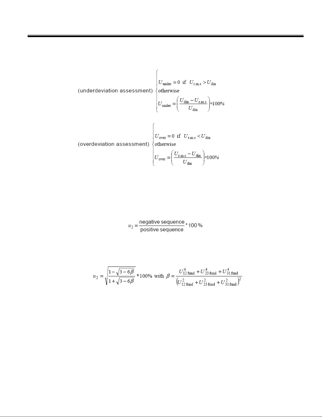
Rapid Voltage Changes: Under-Deviation Assessment and OverDeviation Assessment:
Voltage Unbalance:
The negative sequence component u2 is evaluated by the following ratio, expressed as a
percentage :
For 3-phase systems, this can be written (with Uij fund = phase i to phase j fundamental
voltage):
The zero-sequence u0 component is evaluated by the magnitude of the following ratio,
expressed as a percentage:
MPQ1000-UG-EN Rev 1 Nov 2016
11
Page 18

M
Current Unbalance:
Power:
Instantaneous Power (W) = V sample * I sample
Active Power (P) = V* I * cos θ
Reactive Power (VAR) = V* I * sin θ
Apparent Power (S) (VA) = S = VI
DPF = cos θ
Power Factor = Pf = TPF = P/S
Energy
KWH = KW / Number of Demand Intervals in an Hour
KVARH = KVAR / Number of Demand Intervals in an Hour
KVAH = KVA / Number of Demand Intervals in an Hour
MPQ1000-UG-EN Rev 1 Nov 2016
12
Page 19

THD Measurement -
Where:
Q represents wither cu rrent or voltage
Q
is the r.m.s. value of the fundamental component
1
h is the harmonic order
Q
is the r.m.s. value of the harmonic component of order h
h
H is 50 for the purpose of the compatibility levels in this standard
NOTE: THD takes account of harmonics only.
Mains Signaling Voltage:
Overview of MPQ1000
Performed per IEC 61000-3-8
IEC Flicker:
Performed per IEC 61000-4-15
MPQ1000-UG-EN Rev 1 Nov 2016
13
Page 20

M
M
MPQ1000-UG-EN Rev 1 Nov 2016
14
Page 21

4
MPQ1000 Specifications
SPECIFICATIONS REFERENCE
Sampling Rate 1MHz
RMS Sampling Rate 256
RMS Aggregation 1 Cycle
Event Aggregation 1/2 Cycle
VOLTAGE
Voltage Input Channels 4
Voltage Range 0-1000V AC/DC
Voltage Accuracy 0.1% Udin over range of 10%-150% of Udin
Voltage Crest Factor 1.5 Max
CURRENT
Current Input Channels 4
Current Range 0-6000A (CT Dependent)
Current Accuracy 0.1% of full scale + CT
Current Crest Factor 4.0 Max
FREQUENCY
Fundamental Frequency 42.5-69Hz
Frequency Response DC to 50th Harmonic
Frequency Resolution 0.01Hz
Frequency Accuracy 0.01Hz at 60Hz
Transient Response 1µsec
DEMAND
KW Accuracy Voltage Accuracy * (Current Accuracy +CT)
KVAR Accuracy Voltage Accuracy * (Current Accuracy +CT)
KVA Accuracy Voltage Accuracy * (Current Accuracy +CT)
Phase Angle Error +/-1 Degree
FEATURES
25ºC (77ºF)
Harmonics DC-50th per IEC 61000-4-7
Flicker IEC61000-4-15
Unbalance IEC61000-4-27
MPQ1000-UG-EN Rev 1 Nov 2016
15
Page 22

M
Rapid Voltage Change IEC61000-4-30
Real Time Clock Accuracy Better than +/-0.005%
POWER SUPPLY / CHARGER
Input 90-264VAC (47-63Hz), 79VA Max
Output 24VDC
BATTERY
Battery Type 12VDC NiMH (Use only Megger Battery)
Run Through Time 8 Hours Minimum without CT’s
Charge Time 2 Hours
MEMORY
Memory Type SD Card
Memory Size 32G Max
USB Memory Stick Supported
PHYSICAL
Communications USB & Ethernet
Display VGA
Weight 2.27kg (5.0lbs) Max
Size 255(H) x 175(W) x 55(D) Maximum
ENVIRONMENTAL
Operating Temperature 0ºC to 50ºC
Storage Temperature -20ºC to 60ºC
Humidity 95% NC
IP Rating 51
SAFETY
Channel to Channel Isolation Common Neutral
Safety Standard IEC61010
CAT Rating IV at 600V (BETA units CAT III at 600)
STANDARDS COMPLIANCE
IEC Standard IEC61000-4-30
IEC Flicker IEC61000-4-15
IEC Unbalance IEC61000-4-27
IEC Power Frequency IEC61000-4-28
IEC Harmonics IEC61000-4-7
Standards Test EN50160
CE Standard EN50081-1
CE Standard EN50082-1
MPQ1000-UG-EN Rev 1 Nov 2016
16
Page 23
5
Safety
Warnings and Safety Precautions
WARNING!
Death, serious injury, or fire hazard could result from improper
use/installation of this instrument. Read and understand this
manual before installing this instrument.
Installation of this instrument MUST be performed in compliance with the National
Electric Code and any additional safety requirements applicable to your installation.
Installation, operation and maintenance of this instrument MUST be performed by
qualified personnel only. The National Electrical Code defines a qualified person as one
familiar with the construction and operation of the equipment and the hazards involved.
Safety Precautions
The following safety precautions MUST be taken whenever the Power Quality
instrument is installed.
Wear safety glasses and insulated gloves when making connections to power circuits
Hands, shoes, floor/ground must be dry when making any connection to a power
line
These warnings and safety precautions are to be used where appropriate when following
instructions in this manual.
The equipment could be impaired from improper use. Read the
complete manual before use.
CAUTION!
MPQ1000-UG-EN Rev 1 Nov 2016
17
Page 24

M
WARNING!
The equipment should not be used while its battery door
is removed or if there is any visible damage to the case
or if the hardware holding the unit together has been
loosened.
MPQ1000-UG-EN Rev 1 Nov 2016
18
Page 25

6
MPQ1000 Operation
The following section describes the operation of the MPQ1000 unit. This section will
describe in a step by step manner how to setup, program, install and download data from
the MPQ1000.
Connector Layout / Interconnect
Phase AV Phase BV Phase CV Channel 4 Neutral Earth
Phase AI Phase BI Phase CI Neutral Current
Communication Ports
(USB Stick, USB Port & Ethernet port) located on side of analyzer.
MPQ1000-UG-EN Rev 1 Nov 2016
19
Page 26

M
DC Power Jack
SD Card
Located on the back of the analyzer.
Located on the side of the analyzer
MPQ1000-UG-EN Rev 1 Nov 2016
20
Page 27

Front Panel Keypad Operation
MPQ1000 Operation
Menu Keys
MPQ1000-UG-EN Rev 1 Nov 2016
21
Page 28
M
Menu Flow Charts
MPQ1000-UG-EN Rev 1 Nov 2016
22
Page 29
MPQ1000 Operation
NOTE: Formatting the SD card will NOT erase data or setup files present on the SD
MPQ1000-UG-EN Rev 1 Nov 2016
card.
23
Page 30

M
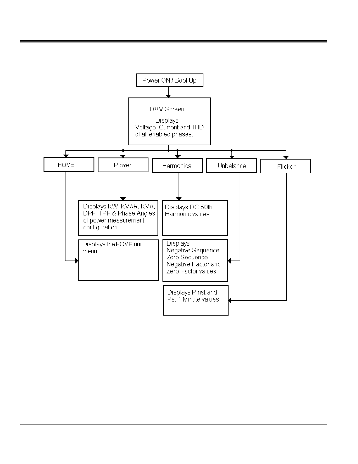
DMM Mode
The MPQ2000 has a real time multi-meter mode. In this mode the analyzer will display
real time voltages, currents, THD, power, phases, unbalance, harmonics and flicker.
The DMM screen will open when the analyzer first powers up.
The DMM screen can also be opened by pressing the DMM short cut key.
The DMM screen consists of 5 different screens.
1. The DMM screen.
This screen will display Real Time Voltages, THD and Currents.
MPQ1000-UG-EN Rev 1 Nov 2016
24
Page 31

MPQ1000 Operation
2. The POWER screen.
This screen will display Real Power, Reactive Power, Apparent Power, Displacement Power Factor
and True Power Factor.
3. The UNBALANCE screen.
This screen will display the Negative Sequence Unbalance and The Zero Sequence Unbalance.
MPQ1000-UG-EN Rev 1 Nov 2016
25
Page 32

M
4. The HARMONICS screen.
This screen will display the Magnitude of the Harmonic Orders.
Use the UP / DOWN arrows to scroll through the harmonic orders.
5. The FLICKER screen.
This screen will display the Instantaneous Flicker and the 1 Minute Flicker Interval.
Note: This screen must be left on for at least 1 minute in order to view the flicker 1
minute interval.
MPQ1000-UG-EN Rev 1 Nov 2016
26
Page 33

Scope Mode
The MPQ2000 has a real time scope mode. In this mode the analyzer will display
voltages and current waveforms, unbalance vectors, harmonics, inter-harmonics and
harmonic direction.
The SCOPE screen can also be opened by pressing the SCOPE short cut key.
The SCOPE screen consists of 3 different screens.
1. The SCOPE or WAVEFORM Screen.
MPQ1000 Operation
This screen will display snapshots of the Voltage and Currents Waveform. This screen is
updated every few seconds.
Use the UP / DOWN arrow keys to scroll through the different phases.
The image can be frozen by arrowing over to the HOLD option and then pressing the
ENTER key.
In the HOLD mode the arrows can be used to zoom in and out of the waveform.
By pressing the WAVEFORM key in the HOLD mode a scan line will open. This will
allow you to view individual values throughout the waveform.
MPQ1000-UG-EN Rev 1 Nov 2016
27
Page 34

M
NOTE: The bottom of the screen will display the key functions of the analyzer for each
screen.
2. The UNBALANCE screen.
This screen will display Voltages, Currents, Phase Angles, Negative Sequence Unbalance, Zero
Sequence Unbalance and a Vector Diagram of the Angles.
Use the UP / DOWN arrow keys to toggle between IEC Unbalance and ANSI
Unbalance.
3. The HARMONICS screen.
This screen will display Harmonics and Inter-Harmonics through the 50th Order.
Use the UP / DOWN keys to scroll through the different channels and to view the
harmonic direction.
MPQ1000-UG-EN Rev 1 Nov 2016
28
Page 35

Configuring the MPQ Unit
Prior to first use the MPQ Unit needs to be configured. This allows the operator to set
the date and time format as well as any operator preferences.
MPQ1000 Operation
NOTE: If these settings are not made then the date and times in the recordings may be
incorrect.
MPQ1000-UG-EN Rev 1 Nov 2016
29
Page 36

M
Configure Date and Time format
1. From the HOME screen select SETUP then press the ENTER key.
2. Select DATE/TIME then press the ENTER
3. Use the UP / DOWN & ENTER
desired date and time formats.
keys to scroll down and select the
key.
MPQ1000-UG-EN Rev 1 Nov 2016
30
Page 37

MPQ1000 Operation
4. Use the UP / DOWN keys to scroll down to TIME ZONE then press the
ENTER key to select.
5. Use the UP / DOWN keys and scroll through the time zones until you find
your time zone. Press ENTER to select the time zone.
6. Use the UP / DOWN keys to scroll down to DAYLIGHT SAVINGS TIME.
Press the ENTER key to toggle between ON and OFF. Select desired mode.
7. When complete, press the BACK button to exit this screen and save the selections.
MPQ1000-UG-EN Rev 1 Nov 2016
31
Page 38

M
Configure unit preferences
1. From the HOME screen select SETUP then press the ENTER key.
2. Select PREFERENCES then press the ENTER
key.
MPQ1000-UG-EN Rev 1 Nov 2016
32
Page 39

MPQ1000 Operation
3. Use the UP / DOWN and ENTER keys to scroll down and select the
desired selections.
From this screen the user can select the following:
1. Change the Voltage and Current Trace colors. (These can be matched to local
standards)
2. Click in the SCOPE field to open the drop down menu. This will allow you to select
the screen to which the SCOPE shortcut key will default.
3. Click in the DMM field to open the drop down menu. This will allow you to select
the screen to which the DMM shortcut key will default.
4. Click in the LINE WEIGHT field to open the drop down menu. From here you can
change the line weight of the traces on the charts..
5. Click in the GRID LINE field to enable or disable grid lines on the charts displayed
on the unit.
6. Change the Auto shutdown time (in minutes). The analyzer will shutdown after this
amount of time providing the analyzer is NOT powered from its AC adapter and the
analyzer is NOT recording.
MPQ1000-UG-EN Rev 1 Nov 2016
33
Page 40

M
Importing / Activating a Setup File
Uploading a Setup File from the PC
Uploading a Setup File from the USB stick
A setup file is used to program the unit to perform different types of recording. Multiple
setup files can be installed into the unit. These setup files can be activated from the front
panel of the unit or using the Megger PQ software.
See the MEGGERPQ Manual.
1. Verify the batteries in the unit are fully charged or plug the unit into an AC source.
2. Power up the MPQ-2000 PQ Analyzer and go to the MAIN Menu.
3. Plug the USB stick into the MPQ-2000 type A USB Port.
4. Scroll down to USB on the Main Menu and press the ENTER key. This will
open the USB Memory Screen.
MPQ1000-UG-EN Rev 1 Nov 2016
34
Page 41

MPQ1000 Operation
5. Scroll down to IMPORT SETUP FROM USB on the USB Memory screen and
press the ENTER key. This will display the setup files on the USB stick.
6. Use the UP / DOWN keys to scroll to the desired setup file and press the
ENTER key. This will import the setup file to the unit.
7. Press the ENTER key to close the IMPORT SETUP COMPLETE message.
MPQ1000-UG-EN Rev 1 Nov 2016
35
Page 42

M
Uploading a Setup File from the SD Card
1. Verify the batteries in the unit are fully charged or plug the unit into an AC source.
2. Power up the MPQ1000 PQ Analyzer and go to the MAIN Menu.
3. Plug the SD card into the MPQ1000 SD Card slot.
4. Scroll down to SD Card on the Main Menu and press the ENTER key. This will
open the SD Card Memory Screen.
5. Scroll down to IMPORT on the SD Card screen and press the ENTER key. This
will display the Setup Files on the SD Card.
6. Scroll down to the desired Setup File and press the ENTER key. This will import
the setup file to the unit.
7. Press the ENTER key to close the IMPORT SUCCESS message.
MPQ1000-UG-EN Rev 1 Nov 2016
36
Page 43

Activating the Imported Setup File
1. Return to the MAIN MENU
2. Scroll down to SETUP on the MAIN Menu and press the ENTER key. This will
display the Setup Files screen.
MPQ1000 Operation
3. Scroll down to SELECT on the Setup Files screen and press the ENTER
This will display the setup files in the unit.
4. Scroll down to the setup file you wish to activate press the ENTER key. This will
activate the setup file.
key.
5. Press the ENTER
MPQ1000-UG-EN Rev 1 Nov 2016
key to close the activated message.
37
Page 44

M
Renaming a Data or Setup File
When renaming a Setup File start at the Select Setup File Screen on the unit.
HOME / SETUP / SELECT
When renaming a Data File start at the Select Data File screen on the unit.
HOME / VIEW DATA
1. Using the UP / DOWN keys highlight the desired file to be renamed.
2. Press the SCOPE button to activate the keypad.
3. Using the UP / DOWN /◄ LEFT /► RIGHT keys navigate to the desired
letter / number.
MPQ1000-UG-EN Rev 1 Nov 2016
38
Page 45

MPQ1000 Operation
4. Press the ENTER key until the desired letter / number is displayed.
5. When the desired name is created scroll over the ACCEPT and press the ENTER
key. The file name will now be changed.
MPQ1000-UG-EN Rev 1 Nov 2016
39
Page 46

M
To backspace, use the "<" symbol.
To enter a dot ".", dash "-", or underscore "_" , use the "1" key
No spaces are allowed in the file names.
MPQ1000-UG-EN Rev 1 Nov 2016
40
Page 47

7
Installing the MPQ1000 Analyzer
WARNING!
Be sure to use all appropriate safety equipment when installing
the MPQ1000 PQ Analyzer. Failure to do so can result in injury
or death.
CAUTION
Inspect all power cords and wires for proper insulation
integrity before connecting to any power source.
WARNING!
Exposure to excessive dust and submersing in water may
The installation procedure consists of:
1. Charging the units battery prior to use.
2. Ensure that the MPQ1000 PQ Analyzer is not exposed to water, excessive dust, and
other hazardous conditions. The MPQ1000 PQ Analyzer is not meant for outdoor use.
3. Making electrical connections.
result in equipment damage.
CAUTION
Turning on analyzer before completing all electrical
connections, or turning off analyzer after removing any
electrical connections may result in erroneous readings.
Always complete all connections before beginning recording. Always stop
recording before removing connections.
MPQ1000-UG-EN Rev 1 Nov 2016
41
Page 48

M
Battery
Battery Charging
Charging the MPQ1000 Battery
Always ensure that the battery is properly charged. It must maintain a 12-volt minimum
for proper recording operation. A battery charge indicator on the MPQ1000 display
allows you to view the batteries state of charge.
NOTE: The battery should be charged prior to recording with the unit powered off.
A DC adapter is provided as standard equipment with the MPQ1000. This adapter both
powers the unit and charges the internal NiMH batteries within the unit.
Plug the AC adapter into the MPQ1000 unit using the DC input jack. Then plug the
adapter into a standard AC outlet (110V-240VAC 50Hz/60Hz). The battery should fully
charge in approximately 2 hours.
Battery Storage
The MPQ1000 NiMH battery self-discharges an average of 1%/ day at room
temperature. If left for 90 days at room temperature, the cells can fully discharge. Cell
reversal can occur, which will damage the cells.
Fully charge the battery before storage. Store it in a cool dry area. Recharge battery pack
within 90 days after initial storage - sooner if stored above 30C.
Installation
1. The MPQ1000 is an IP51 rated device. Ensure that the MPQ1000 PQ Analyzer is
not exposed to water, excessive dust, and other hazardous conditions. The
MPQ1000 PQ Analyzer is not meant for outdoor use.
The MPQ1000 comes with an optional strap for hanging the analyzer.
2. Plug the AC adapter into the MPQ1000 unit using the DC input jack. Then
plug the adapter into a standard AC outlet (110V-240VAC 50Hz/60Hz).
MPQ1000-UG-EN Rev 1 Nov 2016
42
Page 49

Voltage and Current Connections
If you will not be recording demand parameters, voltage and current can be connected to
any input. The connections do not have to be in pairs, but the voltage channels and
current channels must be sequenced.
NOTE: Current probes not purchased from Megger require Megger adapters.
To install the Power Analyzer using current clamps, plug the selected clamps into the
current input connectors then clamp around the source to be measured. An arrow on the
current clamp indicates the direction of the load.
Installing the MPQ1000 Analyzer
Phase AI Phase BI Phase CI Neutral Current
MPQ1000-UG-EN Rev 1 Nov 2016
43
Page 50

M
M
MPQ1000-UG-EN Rev 1 Nov 2016
44
Page 51

8
WIRING DIAGRAMS for Demand Recording
Notes on Wiring Diagrams
1. The Power Analyzer records all voltages and currents that are hooked up providing you
have activated channels in the setup. Even though not all channels may be required for
the power configurations on the following pages, you can connect them to obtain
voltage/current recordings, providing you activate the channel.
2. The vector diagrams shown are for reference and represent the vectors associated with a
balanced resistive load. Reactive currents will rotate the current vectors clockwise or
counterclockwise with respect to the voltages.
3. In the 3-wire configurations, you may select any one wire as a voltage reference, but you
must place current clamps on the remaining two wires.
4. In the 3-wire configurations, the 2-element wattmeter method is used for power
calculations. The third voltage and current can be connected to the Power Analyzer but
will be recorded as RMS data only, providing you activate the channels.
Inspect all power cords and wires for proper insulation
integrity before connecting to any power source.
CAUTION
MPQ1000-UG-EN Rev 1 Nov 2016
45
Page 52

M
VAIA
LOAD
2-WIRE
SINGLE PHASE
SINGLE WATTMETER
ROTATION
N/A
IA V
MPQ1000-UG-EN Rev 1 Nov 2016
46
Page 53

Installing the MPQ1000 Analyzer
V
AVAV
A
A BN
AB
I
IB
LOAD
3-WIRE
SINGLE PHASE
RESIDENTIAL METER
ROTATION
N/A
B
IB I
MPQ1000-UG-EN Rev 1 Nov 2016
47
Page 54

M
A
C
B
VAC
VBC
IA
IB
LOAD
3-WIRE
DELTA CONNECTION
2- WATTMETER METHOD
MPQ1000-UG-EN Rev 1 Nov 2016
48
Page 55

Installing the MPQ1000 Analyzer
A
V
V
A
V
A
N
LOAD
3-WIRE
SPLIT PHASE
2- WATTMETER METHOD
B
AN
BN
I
IB
ROTATION
N/A
BN
IB
I
VAN
MPQ1000-UG-EN Rev 1 Nov 2016
49
Page 56

M
VANV
A
BNA
BN
I
IB
LOAD
3-WIRE
NETWORK METER
ROTATION
ABC
ROTATION
ACB
MPQ1000-UG-EN Rev 1 Nov 2016
50
Page 57

Installing the MPQ1000 Analyzer
VACV
A
CA
LOAD
3-WIRE
OPEN DELTA
2-WATTMETER METHOD
BC
I
IB
MPQ1000-UG-EN Rev 1 Nov 2016
ROTATION
AC-BA-CB
ROTATION
AC-CB-BA
51
Page 58

M
A
VACV
A
C
B
AB
I
ROTATION
ABC
IB
LOAD
3-WIRE
WYE CONNECTION
2-WATTMETER METHOD
ROTATION
ACB
MPQ1000-UG-EN Rev 1 Nov 2016
52
Page 59

Installing the MPQ1000 Analyzer
A
VANVBNV
A
N
C
B
CN
I
IB
IC
LOAD
RED-LEG OPEN DELTA
3-WATTMETER METHOD
ROTATION
AC-BA-CB
4-WIRE
ROTATION
AC-CB-BA
MPQ1000-UG-EN Rev 1 Nov 2016
53
Page 60

M
A
A
VANVBNV
N
C
B
LOAD
4-WIRE
RED-LEG DELTA
3-WATTMETER METHOD
CN
I
IB
IC
ROTATION
AC-BA-CB
MPQ1000-UG-EN Rev 1 Nov 2016
54
ROTATION
AC-CB-BA
Page 61

Installing the MPQ1000 Analyzer
VANVBNV
A
A
C
B
CN
I
IB
IC
LOAD
4-WIRE
WYE CONNECTION
3-WATTMETER METHOD
ROTATION
ABC
ROTATION
ACB
MPQ1000-UG-EN Rev 1 Nov 2016
55
Page 62

M
VANV
A
A
N
LOAD
C
B
BN
I
IB
IC
4-WIRE
WYE CONNECTION
2½- WATTMETER METHOD
ROTATION
ABC
ROTATION
ACB
MPQ1000-UG-EN Rev 1 Nov 2016
56
Page 63

Floating Wye Neutral Measurement
AIBV
V
V
CA
N
Installing the MPQ1000 Analyzer
B
AN
BN
CN
I
IC
LOAD
FLOATING WYE CONNECTION
4-WIRE WYE CONNECTION
3-WATTMETER METHOD
MPQ1000-UG-EN Rev 1 Nov 2016
57
Page 64

M
Verify Active Setup File
1. From the Main Menu scroll down to SETUP and press the ENTER key.
2. This will take you to the SETUP menu. Scroll down to SELECT and press the
ENTER key.
The active Setup File will have an asterisk in front.
MPQ1000-UG-EN Rev 1 Nov 2016
58
Page 65

9
Starting and Stopping a Recording
Before starting a recording is best to verify the current clamps are set to the proper range
and the analyzer is connected properly.
Verify the Input Connections
Before starting any test, verify that you have hooked up all the inputs required for the
active setup program. Press the DMM short cut key to enter the DMM mode. You can
then view all voltage and current values the unit is connected to.
Use the arrow keys to scroll over to the POWER selection. Verify the KW
measurements are positive. If they are not then a current probe may be backwards.
Verify the voltage and current phase angles are correct for the active setup file.
MPQ1000-UG-EN Rev 1 Nov 2016
59
Page 66

M
Starting a Recording
Once the connections are verified, press the RECORD button to start the recording.
The analyzer will verify the inputs and settings before starting the recording. The
analyzer will verify the following:
The default frequency is correct.
The inputs are correct for the power parameters selected.
The current clamps are set to the proper range.
The phase angles are correct for the configuration selected.
MPQ1000-UG-EN Rev 1 Nov 2016
60
Page 67

Starting and Stopping a Recording
If any of the above is found to be incorrect the analyzer will display a message. The
message will indicate what parameters and channel is incorrect and how to correct it.
NOTE: If the range setting on the CT does not match the range in the setup file then the
analyzer will display a message indicating the CT channel that is set incorrectly.
The operator has the option to do the following:
Manually change the range on the CT to the correct range.
Have the analyzer automatically change the range in the setup file to match the range
setting on the CT.
Ignore the mismatch. Please note: if this option is chosen the current values recorded will be
incorrect.
The analyzer will check the CT ranges for each channel individually. Therefore it is
possible to get the same message 3 times. Each message will display a different channel.
MPQ1000-UG-EN Rev 1 Nov 2016
61
Page 68

M
Once the analyzer determines the configuration is correct it will start the recording and
the following screen will appear.
This screen will display the Duration of the Recording, the Time Remaining, the Voltages and
Currents as well as any events that have been captured.
During the recording the mode the analyzer does not display scope mode functions.
The user can use the arrows to scroll over to POWER to view the power and energy
parameters during the recording.
To stop the recording, press the RECORD key again.
If the display on the analyzer is off, pressing the RECORD key will first turn on the
display.
Press the RECORD key a second time to stop the recording.
A message will appear asking if you are sure. Press the ENTER
key and the
recording will now be stopped.
MPQ1000-UG-EN Rev 1 Nov 2016
62
Page 69

10
Downloading Data from the MPQ1000
Transfer data to a PC via SD Card, Ethernet or USB Cable
The data from the MPQ2000 can be retrieved in several different manners.
The data can be transferred through the type B USB Port directly to the PC.
The data can be transferred through the Ethernet Port directly to the PC.
The data can be transferred to a USB stick plugged into the type A USB port.
The data can be imported directly from the SD Card.
See the MEGGERPQ software manual
Transfer data to a USB Stick
1. Power up the MPQ2000 using the power adapter.
2. Insert the USB stick into the type A USB port in the unit.
3. From the MAIN MENU scroll down to SD CARD and then press the ENTER
key. This will display the SD CARD screen.
MPQ1000-UG-EN Rev 1 Nov 2016
63
Page 70

M
4. From the SD CARD scroll down to EXPORT TEST DATA TO USB and then
press the ENTER key.
5. Select EXPORT TEST DATA TO USB then press the ENTER key.
The data transfer will now begin.
6. Once the data is transferred a success message will appear.
NOTE: See AVTMMEGGERPQ manual for transferring data from the USB stick
or the SD card to the PC.
MPQ1000-UG-EN Rev 1 Nov 2016
64
Page 71

11
Viewing Data on the MPQ PQ Analyzer
The MPQ PQ Analyzer will display the recorded data on the unit's display.
The MPQ Analyzer will trend the following data.
RMS Voltage and Current
Power
Energy
Power Factor
THD
Harmonics
Inter-Harmonics
Frequency
Flicker
The MPQ Analyzer will display all the following events.
Sags
Swells
Sub-cycle events
High Speed Transients
THD Events
RVC
Phase Angle Deviation
Mains Signaling Events
All charts and traces support a zoom function and a scan line.
The following sections show how to view the recorded data on the unit.
MPQ1000-UG-EN Rev 1 Nov 2016
65
Page 72

M
Viewing an RMS Chart
Starting from the HOME Screen (Press to open the HOME Screen):
1. Use the UP / DOWN
2. Press the ENTER
Select VIEW DATA Select Data File
key to select an option.
to navigate through the menu options.
See next page for RMS chart description.
MPQ1000-UG-EN Rev 1 Nov 2016
View RMS
Select type of RMS chart then
press ENTER to create chart.
66
Page 73

Displayed
Phase
Viewing Data on the MPQ PQ Analyzer
Trace colors
Scale in
volts
Start date and
time
Select Function: Use SIDE to
SIDE arrows to select different
charts.
Select Phases: Use UP /
DOWN arrows to select
different phases
Scale in Amps
Trace end
date and
time
Zoom / Scan: Press the
ENTER key to enter zoom
mode and use the scan line.
3. To EXIT chart, press the BACK◄ button.
MPQ1000-UG-EN Rev 1 Nov 2016
67
Page 74

M
Viewing a Unbalance Chart
Starting from the HOME Screen (Press to open the HOME Screen):
1. Use the UP / DOWN
2. Press the ENTER
Select VIEW DATA
key to select an option.
to navigate through the menu options.
Select Data File
View Unbalance Chart
See next page for unbalance chart description
MPQ1000-UG-EN Rev 1 Nov 2016
68
Select UNBALANCE then press ENTER
to create chart.
Page 75

Displayed
r
Sequence
Facto
Scale in
percent of
fundamental
Viewing Data on the MPQ PQ Analyzer
Trace colors
Start date and
time
Select Function: Use SIDE to
SIDE arrows to select different
charts.
Select Phases: Use UP /
DOWN arrows to select
different phases
3. To EXIT chart press the BACK◄ button.
Trace end
date and
time
Zoom / Scan: Press the
ENTER key to enter zoom
mode and use the scan line.
MPQ1000-UG-EN Rev 1 Nov 2016
69
Page 76

M
Viewing a Power or Energy Chart
Starting from the HOME Screen (Press to open the HOME Screen):
1. Use the UP / DOWN
2. Press the ENTER
Select VIEW DATA Select Data File
key to select an option.
to navigate through the menu options.
View POWER CHART
See next page for Power and Energy chart description.
MPQ1000-UG-EN Rev 1 Nov 2016
70
Select POWER or ENERGY then press
ENTER to create chart.
Page 77

Displayed
r
A
Sequence
Facto
Scale in
KW / KVA &
KV
Viewing Data on the MPQ PQ Analyzer
Trace colors
Start date and
time
Select Function: Use SIDE to
SIDE arrows to select different
charts.
Select Phases: Use UP /
DOWN arrows to select
different phases
3. To EXIT chart press the BACK◄ button.
Trace end
date and
time
Zoom / Scan: Press the
ENTER key to enter zoom
mode and use the scan line.
MPQ1000-UG-EN Rev 1 Nov 2016
71
Page 78

M
Viewing a THD Chart
Starting from the HOME Screen (Press to open the HOME Screen):
1. Use the UP / DOWN
2. Press the ENTER
Select VIEW DATA Select Data File
key to select an option.
to navigate through the menu options.
View THD CHART
See next page for THD chart description.
MPQ1000-UG-EN Rev 1 Nov 2016
72
Select THD then press ENTER to
create chart.
Page 79

Displayed
Scale in
percent of
fundamental
Viewing Data on the MPQ PQ Analyzer
Trace colors
Phase
Start date and
time
Select Function: Use SIDE to
SIDE arrows to select different
charts.
Select Phases: Use UP /
DOWN arrows to select
different phases
3. To EXIT chart press the BACK◄ button.
Trace end
date and
time
Zoom / Scan: Press the
ENTER key to enter zoom
mode and use the scan line.
MPQ1000-UG-EN Rev 1 Nov 2016
73
Page 80

M
Viewing a Frequency Chart
Starting from the HOME Screen (Press to open the HOME Screen):
1. Use the UP / DOWN
2. Press the ENTER
Select VIEW DATA Select Data File
key to select an option.
to navigate through the menu options.
View FREQUENCY CHART
See next page for Frequency chart description
MPQ1000-UG-EN Rev 1 Nov 2016
Select Frequency then press ENTER to
create chart.
74
Page 81

Scale in Hertz
Start date and
time
Viewing Data on the MPQ PQ Analyzer
Trace end
date and
time
Select Function: Use SIDE to
SIDE arrows to select different
charts.
3. To EXIT chart press the BACK◄ button.
Zoom / Scan: Press the
ENTER key to enter zoom
mode and use the scan line.
MPQ1000-UG-EN Rev 1 Nov 2016
75
Page 82

M
Viewing a Harmonics / Inter-Harmonics Chart
Starting from the HOME Screen (Press to open the HOME Screen):
1. Use the UP / DOWN
2. Press the ENTER
Select VIEW DATA
key to select an option.
to navigate through the menu options.
Select Data File
Select harmonic sequence then press
ENTER to create chart.
See next page for Harmonic chart description
MPQ1000-UG-EN Rev 1 Nov 2016
Select Harmonics or Inter-Harm
(Inter-Harmonics).
76
Page 83

Displayed
Phase
Scale in
percent of
fundamental
Viewing Data on the MPQ PQ Analyzer
Trace colors
Start date and
time
Select Function: Use SIDE to
SIDE arrows to select different
charts.
3. To EXIT chart press the BACK◄ button.
The following screen shall be displayed.
Select Phases: Use UP /
DOWN arrows to select
different phases
Trace end
date and
time
Zoom / Scan: Press the
ENTER key to enter zoom
mode and use the scan line.
4. Scroll to RETURN and press the ENTER
MPQ1000-UG-EN Rev 1 Nov 2016
77
key.
Page 84

M
Viewing a Flicker Chart
Starting from the HOME Screen (Press to open the HOME Screen):
1. Use the UP / DOWN
2. Press the ENTER
Select VIEW DATA Select Data File
key to select an option.
to navigate through the menu options.
Select Short Term or Long Term then
press ENTER to create chart.
See next page for Flicker chart description.
.
MPQ1000-UG-EN Rev 1 Nov 2016
78
Select Flicker
Page 85

Displayed
Phase
Scale in
percent of
fundamental
Viewing Data on the MPQ PQ Analyzer
Trace colors
Start date and
time
Select Function: Use SIDE to
SIDE arrows to select different
charts.
3. To EXIT chart press the BACK◄ button. The following screen shall be displayed.
Select Phases: Use UP /
DOWN arrows to select
different phases
Trace end
date and
time
Zoom / Scan: Press the
ENTER key to enter zoom
mode and use the scan line.
4. Scroll to RETURN and press the ENTER
MPQ1000-UG-EN Rev 1 Nov 2016
key.
79
Page 86

M
Viewing an Event Chart
Starting from the HOME Screen (Press to open the HOME Screen):
1. Use the UP / DOWN
2. Press the ENTER
Select VIEW DATA Select Data File
key to select an option.
to navigate through the menu options.
Select type of event using the side to side
arrows, then press ENTER to select
See next page.
MPQ1000-UG-EN Rev 1 Nov 2016
Select Events
80
Page 87

Viewing Data on the MPQ PQ Analyzer
t
r
r
Select the date the event occurred.
Numbe
Scale
in volts
amps
Start date
and time
Even
o
Select Event then press ENTER to create
chart.
Event
Channel
Start Date and
Time
Event
Duration
Minimum,
Maximum
and Average
values
recoded
during the
event.
Trace end
date and
time
Zoom / Scan: Press the
ENTER key to enter zoom
mode and use the scan line.
3. To EXIT chart press the BACK◄ button and scroll through the options.
MPQ1000-UG-EN Rev 1 Nov 2016
81
Page 88

M
M
MPQ1000-UG-EN Rev 1 Nov 2016
82
Page 89

12
Unit Maintenance
Battery Replacement
NOTE: Battery Life: Typically 500 charge / discharge cycles.
The battery life may vary depending on how the battery is maintained.
The following procedure should be followed when replacing the MPQ1000 battery:
1. If the unit is on, turn the unit off by pressing and releasing the ON/OFF button.
2. Disconnect the external power supply, if it is connected.
3. Remove the stand to gain full access to the battery compartment door.
Stand
Screws
4. Loosen the battery compartment door retaining screws and remove the battery
MPQ1000-UG-EN Rev 1 Nov 2016
compartment door.
83
Page 90

M
Battery
5. Lift out the battery from the top end and rotate to the side.
Connector
Battery
6. Grasp the wires between the battery and the connector and pull straight up until the
connector unplugs from the PQ-1000.
7. Connect a new battery to the PQ-1000 by aligning the battery connector to the pins
MPQ1000-UG-EN Rev 1 Nov 2016
and pressing it in place.
84
Page 91

Battery
Compartment Wall
Battery
Compartment
Floor
Viewing Data on the MPQ PQ Analyzer
Battery
Connector
8. Place the battery in the battery compartment with the wires under it.
9. Put the battery compartment door back in place and tighten the retaining screws.
10. Put the stand back in place.
11. Turn on the PQ-1000 by pressing and releasing the ON/OFF button. The battery
status indication should indicate 0%. The battery status indicator must be initialized
before it will display the true charge level of the battery. This is done by discharging
the battery to below 10% of its capacity.
12. Go to the SETUP > PREFERENCES screen by pressing the HOME key, scrolling
down to the SETUP menu item and pressing the ENTER
down to the PREFERENCE menu item and pressing the ENTER
key and then scrolling
key.
13. Select the AUTO-OFF box and, if necessary, toggle it to its un-checked state by
pressing the ENTER
key. This will allow the unit to remain on even when not
being actively used.
14. Allow the unit to run until the battery status indicator shows a value of between 1
and 9%. The unit may be used during this discharge period, if desired; but, it should
be noted that the battery charge level indicated on the display will not be accurate
until the battery level has fallen below 10% capacity. If desired, the unit can be left
running and allowed to fully discharged and shut down.
MPQ1000-UG-EN Rev 1 Nov 2016
85
Page 92

M
HELP Screen
Once the battery level has fallen below 10%, the battery status indicator has been
initialized. The external power supply will need to be connected to charge the battery.
The unit may be turned on and used during this charge period, if desired
To open the HELP screen push the HELP short cut button.
This screen will display the firmware versions of the MPQ analyzer, hardware version,
serial number, calibration date as well as the IP address of the analyzer if it is connected
to a network.
MPQ1000-UG-EN Rev 1 Nov 2016
86
Page 93

13
Spare Parts
Part No. Description
2008-369 Battery Pack
JA1009 Current Connector Dust Covers
2006-093 Wire Stand
MPQ1000-UG-EN Rev 1 Nov 2016
87
Page 94

M
M
MPQ1000-UG-EN Rev 1 Nov 2016
88
 Loading...