

Page 1
MOM2
Micro-ohmmeter
Handheld High Current Micro-ohmmeter
n
Up to 240 A
n
Bluetooth® headset for audible pass/fail
testing against adjustable limits
n
Battery powered
n
Handheld, lightweight – 2.2 lb (1 kg)
n
Safe test – DualGround
n
Auto range: 1 µΩ to 1000 mΩ
n
Ultra capacitor technology (patent
™
pending)
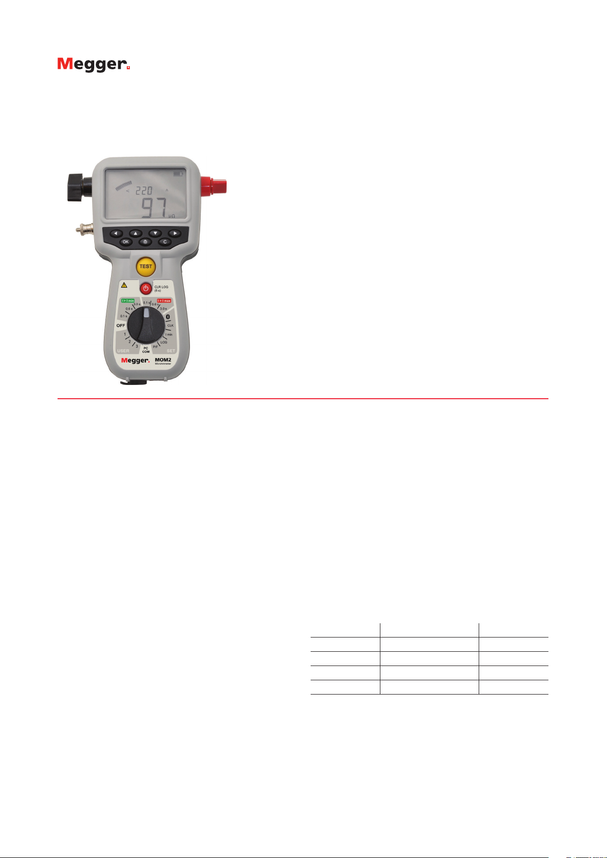
MOM2
DESCRIPTION
The MOM2 Micro-ohmmeter is a lightweight, handheld
unit designed to deliver up to 240 Amps and measure the
resistance of circuit breaker contacts, bus-bar joints, and
other high-current links. This product is designed with
safety, ease of use and versatility in mind.
The MOM2 can be used anywhere to measure a low
resistance value with high accuracy. With the MOM2,
it is possible to make measurements according to the
DualGround™ method. This means that the test object will
be grounded on both sides throughout the test giving a
safer, faster and easier workflow.
Its ruggedness and light weight make the MOM2 very
suitable for field work, such as in substations. The unit
comes with a strong rubber holster accessory which makes it
extra durable. The MOM2 is capable of testing for a full day
without recharge. It can store 190 test values and transfer
test data to a PC via Bluetooth.
The Bluetooth feature can also be used in conjunction with
the wireless headset to provide an audible pass/fail signal
against user-adjustable limits as tests are performed.
High Current Generation Using Ultra Capacitor
The MOM2 uses an ultra capacitor to generate the highoutput current. Ultra capacitors are able to store huge
amounts of energy compared to conventional capacitors. In
addition, they can deliver very high currents during discharge
as a result of their very low internal resistance.
While testing, the capacitor is discharged through the
test object. The voltage drop across and the current flow
through the test object are continuously and synchronously
sampled. The resistances calculated from the individual
samples are then averaged to obtain the final value.
APPLICATIONS
The MOM2 test system is designed to serve a number of
applications. The most common are contact resistance
measurements of low-, medium- and high-voltage breakers
and also at bus-bar joints, and other high current links.
If the contact resistance is too high, this will lead to power
loss and temperature rise, which often leads to serious
trouble. To avoid such problems, it is necessary to check the
resistance at regular intervals.
The following table demonstrates how important low
resistance is at high currents:
Current Contact resistance Power loss
10 kA 1 mΩ 100 kW
10 kA 0.1 m Ω 10 kW
1 kA 1 mΩ 1 kW
1 kA 0.1 m Ω 100 W
At 10 kA a contact with the resistance 0.1 mΩ gives a
power loss of 10 kW. This power loss in one single point
will definitely confer a temperature rise, which may result in
overheating and possibly premature failure.
Page 2
MOM2
Handheld High Current Micro-ohmmeter
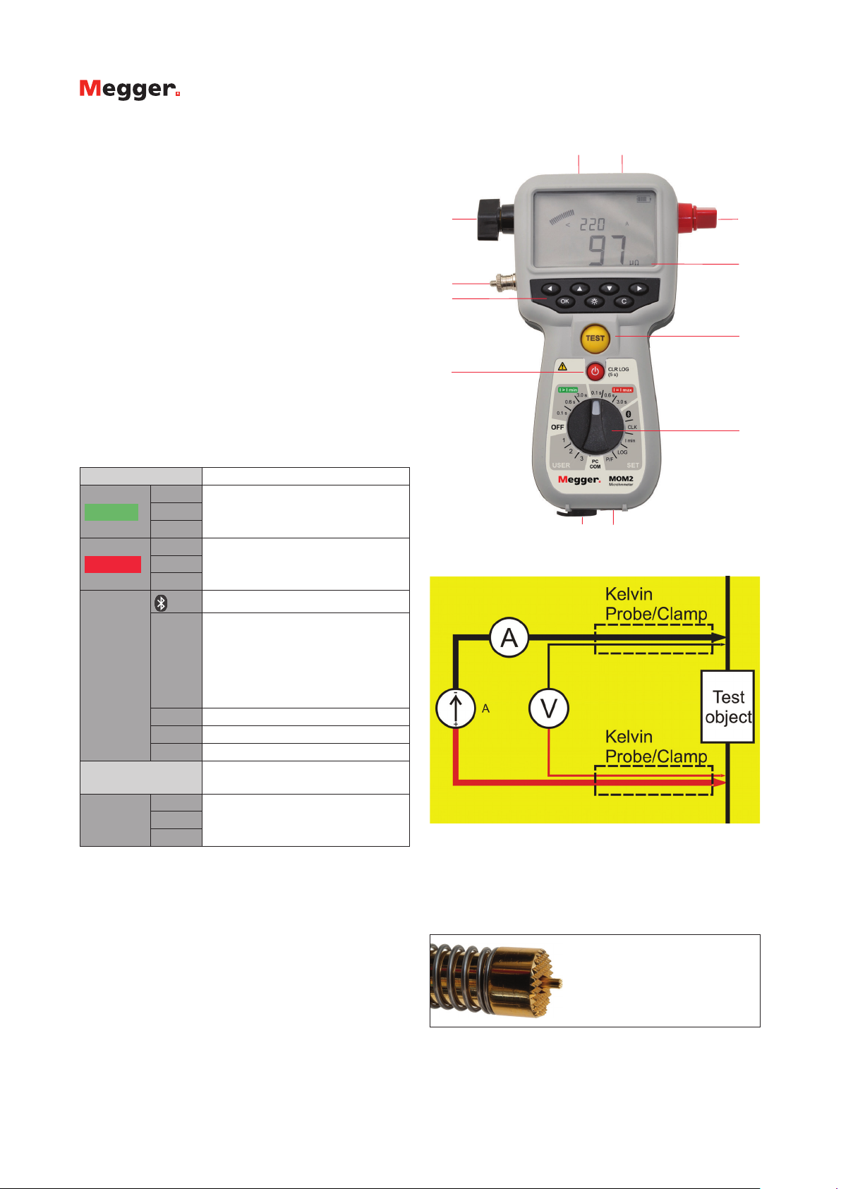
INSTRUMENT FRONT VIEW
1. Current output terminal (-)
2. Current output terminal (+)
3. Display
n
The display offers a combination of analog arc and a
dual digital readout:
n
Analog arc:
Indicates level of the capacitor charge.
n
Dual digital display:
Large main digital readout for good visibility of all
main measurement results
Second digital display for additional data.
4. Ground (earth) terminal
5. Keys for navigation and to make settings in the display
6. TEST-button
7. Stand-by/Wake up (Press shortly to toggle)
Clear log (Press and hold for 5 seconds)
8. Function selector
OFF
I > I min
I = I max
0.1 s
0.6 s
3 s
0.1 s
0.6 s
3 s
Measurement time with
minimum current guarantee
Measurement time with max. charge
Bluetooth “pair units”
CLK
Set date and time
Set volume for the internal
loudspeaker
SET
Discharge the MOM2 internal
capacitor
PC COM
USER
I min
LOG
P/F
1
2
3
Minimum current guarantee setting
Data log settings
Pass/Fail settings
PC communication
(dump data to PC)
Stored settings. Set from PC,
MOM2Win
9. Connector for the voltage (–) sense lead
10. Connector for the voltage sense (+) lead and the trig
function
11. Connector for the battery charger
12. Battery charger indicator
9 10
1 2
3
4
5
6
7
8
11
12
4 wire Kelvin test
The Kelvin probes (included in BD-59090) are used for a 4-wire Kelvin
test. This is a way of measuring continuity resistances ensuring all
contact and lead resistances are compensated for, allowing a much
greater accuracy in measurements. Each Kelvin probe assembly has two
probe tips: one tip is for the current generated; the other will measure
the very small voltage present.
The Kelvin clamps (included in BD-59092) use the same principle.
The "double" probe tip showing the springy center tip
Page 3

MOM2
Handheld High Current Micro-ohmmeter
APPLICATION EXAMPLES
Circuit Breaker testing
n
Test of circuit breaker contacts
n
Test of the connections to the breaker
Testing of Bus-bar
n
Test of Bus-bar joints
n
Test of connections
Everywhere you need to test a low resistance/
high current connection
n
Switches
n
Disconnecting devices
n
Safety ground connections
n
Welding points
n
Fuses
n
Cables
BOTH SIDES GROUNDED
Within electrical power utilities, switchgear owners and
service companies, there is an increased emphasis on
efficiency of operations, maintenance and service levels.
There is an increased emphasis on health, safety, and
environmental compliance. Experience has also shown
demands for shorter time periods for testing, while the
switchgear is less and less available to be taken out of
service.
Many utilities require safety grounds to remain in place
during station outages, and the MOM2 was designed with
this field safety constraint in mind. DualGround means that
the test object will be grounded on both sides throughout
the test giving a safer, faster and easier workflow. Minimum
time is spent in the substation and focus is on the test rather
than the equipment.
Conventional vs. DualGround
Site preparation (isolate work
area, apply safety ground, issue
permit to work)
Hook up test equipment. Issue
sanction for test
Authorized person removes the
ground
Perform testing Safe testing with both sides
Authorized person applies
ground
Cancel sanction for test.
Disconnect test equipment
Site closing (cancel permit to
work, disconnect ground)
Site preparation (isolate work
area, apply safety ground, issue
permit to work)
Hook up test equipment. Issue
sanction for test
Risky step left out
grounded
Risky step left out
Cancel sanction for test.
Disconnect test equipment
Site closing (cancel permit to
work, disconnect ground)
Hold probes / attach Kelvin clamps to CB and press trig / TEST button.
A signal indicates whether test was pass or fail and result is logged in
unit for later dump to PC.
Traditional measurement from ground. Injection is done through
existing grounding cable (earthing). Optional cable kit is needed.
Available kits have 5, 10 or 15 m cables.
Equipment and methods that supports
DualGround™ testing are associated with the
DualGround symbol. This symbol certifies the use
of groundbreaking technology and methods that
enables a safe, fast and easy workflow with both
sides grounded throughout the test.
Measurement on CB with both sides grounded, DualGround.
Page 4

MOM2
Handheld High Current Micro-ohmmeter
SPECIFICATIONS
Specifications are valid at fully charged batteries and an ambient
temperature of +25°C, (77°F). Specifications are subject to change
without notice.
Environment
Application field For use in high-voltage substations
and industrial environments.
Temperature
Operation* -20ºC to +50°C (-4°F to +122°F)
Storage -40ºC to +70ºC (-40°F to +158°F)
Relative humidity %RH 5%-95%, non condensing
Pollution degree 2
Shock IEC 60068-2-27
Vibration IEC 60068-2-6
Transport ISTA 2A
*Battery operation temperature 0ºC to +50° (32°F to +122°F)
*Battery charging temperature +10ºC to +40° (50°F to +104°F)
General
Battery power Five AA (HR6) 2700 mAh NiMH cells
Recharge time < 12 h
Typical recharge time at
25°C
Battery charger
Mains voltage 100 - 250 V AC, 50 / 60Hz
Power consumption 60 W
Protection Against wrong battery type, low/high
Real time clock battery life ≥10 years
Audible feedback Different buzzer sounds
User presets 3
Field calibration Yes
Encapsulation IP54
Dimensions
(excl. binding posts)
Weight 2.2 lbs (1.0 kg) instrument only
CE-marking
EMC 2004/108/EC
LVD 2006/95/EC
3 h
temperature
217 x 104 x 72 mm
8.5 x 4.1 x 2.8 in.
11 lbs (5.0 kg) with accessories and
carrying case
Outputs + / –
Range > 100 A DC (R < 2 mΩ)
Output voltage (max) 2.5 V DC
Generation duration Selectable: 0.1 s, 0.6 s, 3 s
Recovery time at I min set to 100 A
and load 100 μΩ
Generation time Max Typ
0.1 s 10 s 8 s
0.6 s 20 s 16 s
3 s 130
s
Inputs
SENSE + / –
Connector 4 mm banana jack
Voltage ±3 V DC
Trigger input Threshold 8 V DC
DC IN 12 – 24 V DC, 2 A max
Logger
Logger, Data Label. Timestamp, I max, I min, I Limit,
Resistance, Meas.time, P/F limit
Labeling schemes Circuit breaker oriented or diary
number
Capacity 190 measurements
Wireless communication
Headset Bluetooth
PC communication Bluetooth
100 s
INCLUDED ACCESSORIES
Measurement section
Minimum current
guarantee
Pass / Fail Settable from 1 µΩ to 1999 mΩ
Number of measurements
on fully charged batteries
Interference suppression Yes
Range 0 - 1000 mΩ
Range selection Auto
Resolution
0 – 999 µΩ 1 µΩ
1.0 – 9.99 mΩ 0.01 mΩ
10.0 – 99.9 mΩ 0.1 mΩ
100 – 1000 mΩ 1 mΩ
Accuracy
0 – 1999 µΩ ±1 % of reading ±1 digit
2 – 1000 mΩ ±2 % of reading ±1 digit
Selectable 50 A / 100 A
Valid at resistance ≤2mΩ
typ. 2200 at I min = 50 A and 0.1 s
typ. 800 at I min = 100 A and 0.1 s
MOM2 shown with transport case, charger, rubber holster, carrying
strap, belt clip, MOM2 Win software.
Kelvin probes (incl. in BD-59090)
Page 5

MOM2
MOM2
Handheld High Current Micro-ohmmeter
Handheld High Current Micro-ohmmeter
OPTIONAL ACCESSORIES
Bluetooth headset
Calibration kit
Connection plate, used with the
cable kits
Bluetooth dongle
Soft carrying case
ORDERING INFORMATION
Item Cat. No.
MOM2 Micro-ohmmeter including:
2 x 1.3 m (4 ft) test cables Kelvin probes
(one with trig button) transport case,
charger, rubber holster, carrying strap,
belt clip, MOM2 Win
MOM2 Micro-ohmmeter including:
1.3 m (4 ft) test cable red with Kelvin clamp
3 m (10 ft) test cable black with Kelvin clamp,
transport case, charger, rubber holster,
carrying strap, belt clip, MOM2 Win
MOM2 Micro-ohmmeter including:
1.3 m (4 ft) test cable red with Kelvin clamp
5 m (16 ft) test cable black with Kelvin clamp,
transport case, charger, rubber holster,
carrying strap, belt clip, MOM2 Win
Optional Accessories
Test cables with Kelvin probes 2 x 1.3 m (4 ft)
(one with trig button)
Test cables with Kelvin clamps 1.3 m (4 ft) red,
3 m (10 ft) black
Test cables with Kelvin clamps 3 m (10 ft) black GA-00372
Test cables with Kelvin clamps 1.3 m (4 ft)
black, 16 mm
2
Test cables with Kelvin clamps 5 m (16 ft) black GA-00374
Test cables with Kelvin clamps 10 m (33 ft)
black, 16 mm
2
Cable kit 5 m
Current cable 0.5 m (1.6 ft), connection plate
and sense cables 5 m (16 ft), ground cable
Cable kit 10 m
Current cable 0.5 m (1.6 ft), connection plate
and sense cables 10 m (33 ft), ground cable
Cable kit 15 m
Current cable 0.5 m (1.6 ft), connection plate
and sense cables 15 m (49 ft), ground cable
Bluetooth headset and dongle for PC XC-06000
Calibration kit BD-90002
Soft carrying case for MOM2, charger & cables GD-00620
BD-59090
BD-59092
BD-59093
GA-90000
GA-90001
GA-00373
GA-00376
GA-00380
GA-00382
GA-00384
UNITED STATES
Megger
2621 Van Buren Avenue
Norristown, PA 19403 USA
T +610-676-8500
T +866-254-0962
F +610-676-8625
SWEDEN
Megger Sweden AB
Rinkebyvägen 19
SE-182 36 DANDERYDT
+46 8 510 195 00
F +46 8 510 195 95
E seinfo@megger.com
Other Technical Sales Offices
Dover UK, Dallas USA, College Station
USA, Sydney AUSTRALIA, Ontario CANADA,
Trappes FRANCE, Oberursel GERMANY,
Aargau SWITZERLAND, Dubai UAE, Mumbai
INDIA, Johannesburg SOUTH AFRICA, and
Chonburi THAILAND
Registered to ISO 9001 and 14001
Subject to change without notice.
MOM2_DS_US_V15
www.megger.com
Megger is a registered trademark
 Loading...