

Page 1

BM15/MJ15
Insulation Testers
USER GUIDE
GUIDE DE L’UTILISATEUR
GEBRAUCHSANLEITUNG
M
GUÍA DEL USUARIO
Page 2

CONTENTS GUIDE DE L’UTILISATEUR - P.14 GEBRAUCHSANLEITUNG - S.26 GUÍA DEL USUARIO - P.38
Safety Warnings 3
General Description 4
Features and Controls 5
Working with Capacitive Loads 6
Operation
Preliminary Checks 7
Battery Replacement 7
Voltage Measurement 8
Insulation Testing 8
Choice of Test Leads 8
Using the Guard terminal 9
Specification 10
Accessories 12
Repair and Warranty 13
Before using the instrument, follow the separate instructions provided to fit
either the locking or non-locking test button.
If the locking button is fitted, extra care must be taken. See page 6.
Symbols used on the instruments
F Risk of electric shock.
G Caution, refer to accompanying documents
t Equipment protected throughout by Double Insulation
(Class II)
c Equipment complies with current EU Directives
2
Page 3

GSAFETY WARNINGS
■ ‘Safety Warnings‘ and ‘Working with Capacitive Loads‘ must be read and understood before the instrument is used. Safety
precautions must be observed during use.
■ The circuit under test must be switched off, de-energised and isolated before any test connections are made.
■ Circuit connections must not be touched during a test.
■ On completion of a test, decaying voltage across the terminals is indicated on the display. Capacitive load circuits must be discharged
to below 60 V before disconnecting the test leads.
■ Capacitive load circuits should be shorted with a shorting link after discharge.
■ Remove the test leads from the instrument before opening the battery compartment.
■ Test leads and crocodile clips must be in good order, clean and with no broken or cracked insulation.
■ The instrument should not be used if any part of it is damaged.
■ U.K. Safety Authorities recommend the use of fused test leads when measuring voltage on high energy systems. See ‘Choice of Test
Leads‘.
NOTE
The instruments must only be used by suitably trained and competent persons.
NOTE
Users of this equipment and or their employers are reminded that Health and Safety Legislation requires them to carry out valid risk assessments of
all electrical work so as to identify potential sources of electrical danger and risk of electrical injury such as from inadvertent short circuits. Where the
assessments show that the risk is significant then the use of fused test leads constructed in accordance with the HSE guidance note GS38 ‘Electrical
Test Equipment for use by Electricians’ should be used. See ‘Choice of Test Leads’.
3
Page 4

GENERAL DESCRIPTION
BM15, and MJ15 testers are completely self contained instruments designed
for high voltage insulation resistance testing in the maintenance and servicing
of rotating plant machinery, transformers, switchgear and industrial
installations.
Tests can be performed at 500 V, 1000V, 2500 V or 5000 V. Insulation measuring
range is 100 kΩ to 20 GΩ and Infinity. Automatic discharge for capacitive
circuits under test is provided and decaying voltage displayed.
A guard terminal can be used to minimise the effects of surface leakage when
carrying out insulation resistance tests.
Tests are initiated by pressing the BM15 ‘Test’ button (or by turning the MJ15
generator handle). Releasing the ‘Test’ button (or ceasing handle rotation)
causes the instrument to default to ac/dc voltmeter mode, with a discharge
resistor internally connected across the terminals. This feature will give
decaying voltage indication following the testing of equipment possessing
capacitance.
The moving coil meter operates a black pointer to display the readings on a
single logarithmic black scale on a white scale-plate for clarity of reading. The
movement is resiliently mounted for field use.
A slide - in ‘Pass Band‘ overlay can be inserted over the display. Appropriate
Pass/Fail bands can be marked on these windows with a permanent marker for
‘Go / No Go’ testing.
BM15 is powered by eight 1,5 V (IEC LR6) cells.
Normal power for the MJ15 is by low voltage, hand cranked, brushless a.c
generator. Fitting the battery container supplied, with eight 1,5 V IEC LR6 cells
gives the instrument a dual (independent) supply capability. Both instruments
are fitted with a battery check range, operated by pressing the ‘Test‘ push
button. Cranking the handle too slowly (<180 RPM) results in an unstable
pointer reading. Excess handle speed cannot harm the instrument as the
output voltage is electronically regulated.
The case is robust, yet light-weight, made from a flame retardant ABS, with a
polycarbonate display window. Mounted on top of the case is a 6 position,
rotary, range selection switch and a ‘Test‘ push button.
Three recessed sockets are provided, and marked ‘+’, ‘-’ and ‘G’. These have
safety covers which open when the plugs are inserted. When inserted into the
sockets, the shrouded test lead plugs lock into position. They are released by
twisting the plug a quarter turn and pulling out.
For this reason, only the test leads supplied or suitable Megger replacement
ones should be used.
Design safety features include:
■ External voltage, a.c. or d.c., displayed.
■ Load automatically discharged at the end of a test, and decaying
voltage displayed.
■ Test leads can lock into the case to prevent accidental disconnection.
4
Page 5

FEATURES AND CONTROLS
Rotary Selector
Switch
Non Locking Button
(recommended
option)
Generator Handle (MJ15)
Locking Button
(Extra care must
be taken if this
option is chosen.
See page 6)
- Terminal
Guard Terminal
+ Terminal
TO INSERT TERMINAL PLUGS, PUSH IN - TO RELEASE, TWIST A QUARTER TURN AND PULL OUT
5
Page 6

WORKING SAFELY WITH CAPACITIVE LOADS
G
Circuit connections and the instrument terminals may become
hazardous when connected to Capacitive loads.
1. These instruments are designed to safely charge and discharge
capacitive loads up to 5 µF. To safeguard against malfunction however,
you are advised to take your own precautions when working with
capacitive loads. Remember that when charged, even low value
capacitors can be fatal on contact .
2. Extra care must be taken if the locking Test button is selected.
3. Circuit connections must not be touched when testing.
Do not forget to release a locked Test button and discharge
any capacitance before touching the item under test or
disconnecting the test leads.
4. Care must be taken to prevent capacitive circuits becoming
disconnected during a test, leaving the circuit in a charged state.
5. On completion of a test, the instrument indicates circuit decaying
voltage. Do not disconnect test leads until the load capacitance has
discharged to below 60 V.
6. The voltmeter and automatic discharge feature of the instruments
should be regarded as additional safety features and not a substitute
for normal safe working practice.
7. If any part of the instrument is damaged, it should not be used, but
returned to the manufacturer or an approved service organization for
repair.
6
Page 7

PRELIMINARY CHECKS
Preliminary Performance Checks
The instrument will operate in any position, but best results are achieved
when the instrument is face up, on a firm level surface. This is particularly true
for hand cranked units to obtain a crank speed of >180 rev/min.
1) If battery cells are fitted, switch to Battery Check range and press the
‘Test‘ push button. Confirm that the pointer settles within the battery
symbol portion of the scale.
2) With the test leads disconnected, set the rotary selector switch to the
appropriate insulation range, press and hold down the ‘Test‘ button,
(or turn the generator handle). The meter pointer should move up the
scale briefly and then return to the ‘∞ ‘ (infinity) position on the scale.
This establishes that there is no leakage through the instrument itself.
3) Check that the test leads and crocodile clips are in good order, clean
and with no broken or cracked insulation. Connect two of the test
leads to the ‘+’ and ‘-’ terminals and ensure that their clips are not
touching anything.
4) Press the ‘Test‘ button again (or turn the generator handle) and
observe the meter pointer. The pointer should rest over the ‘∞‘
position on the scale. If it does not, the test leads may be faulty and
should be inspected more closely for damage. Replace them if
necessary.
5) Connect the test lead clips together, press the ‘Test‘ button (or turn the
generator handle) and observe the meter pointer. The meter should
read ‘0Ω‘. If it indicates infinity or a high resistance value the leads
may be open circuit and should be inspected further. Replace them if
necessary. (Shorting the leads together and obtaining a ‘0 Ω‘ reading
also indicates that the instrument is working).
Battery Replacement
GWARNING
The battery contacts are not isolated from the test leads. Remove the test
leads from the instrument before opening the battery compartment.
The cells are housed in a battery compartment in the base of the instrument.
To change the cells, use a screwdriver to remove the battery cover securing
screws and lift off the battery compartment cover. Observing the correct
polarity as marked on the battery housing, install 8 replacement IEC LR6 (AA)
cells. Replace and secure the battery compartment cover on completion.
7
Page 8

OPERATION
Voltage measurement
When switched to the ‘V’ position, the instrument measures up to 600 V a.c.
to the specified accuracy of the instrument. DC voltage is also indicated on the
display, but not to the specified accuracy. When not testing (i.e. in standby
mode) and connected to a live circuit, the instruments default to voltmeter (0
to 600 Volts a.c. or d.c.) irrespective of the rotary switch position. Any voltage
present will immediately be shown. Thus indication is given that the item has
not been completely de-energized. The instrument also monitors circuit
discharge when the ‘Test‘ button is released following an insulation test on a
capacitive item, e.g. a long cable.
Insulation Testing
After connecting the test leads to the instrument and carrying out the
Preliminary Performance Checks:
1) Set the selector switch to the required test voltage. Connect the test
leads to the isolated circuit to be tested, as follows:-
(a) For insulation tests to earth (ground):- Connect either test
lead to earth (ground) or the frame of the equipment,and
the other lead to that part of the circuit to be tested.
b) For insulation tests between wires:- Connect a lead to the
core of each of the wires.
2) Press the ‘Test‘ button (or turn the generator handle).
3) The meter pointer will indicate the value of insulation resistance on
the Ω scale.
If a capacitive circuit is tested, the pointer will initially deflect towards 0 Ω and
then gradually rise to its final steady value as the capacitance is charged up to
the output voltage of the tester.
If several successive readings of ∞ (infinity) are obtained, connect the two
farthest ends of the test leads together and carry out a check on the leads. A
0Ω reading should result which double checks that the leads are not
disconnected or broken and therefore, the insulation resistance readings are
correct.
Capacitive circuits automatically discharge through the tester when the ‘Test‘
button is released. Decaying discharge voltage will be indicated on the voltage
scale. Wait a few moments for the voltage to decay to below 60 V before
disconnecting the test leads.
Do not forget to release a locked Test button, and discharge
any capacitance before touching the item under test, or
disconnecting the test leads.
Choice of Test Leads
BM15/MJ15 are supplied with three unfused leads terminated in crocodile
clips. These are the best leads to use for insulation tests on non-live circuits.
The crocodile clips ensure that any capacitive load remains connected until it
is automatically discharged at the end of a test.
GS 38 (UK Safety Authority Guidance Note) advises the use of fused test prods
if the instrument is to be used for making voltage measurements on live, high
energy circuits. These leads are available as an optional extra. See
‘Accessories’.
Fused prods must not be used for insulation testing. If the fuse should
rupture, or the prods lose contact during a test, the system under test would
remain charged without any apparent evidence of danger!
8
Page 9

Using the Guard terminal (G)
For basic insulation tests and where there is little possibility of surface leakage
affecting the measurement, it is unnecessary to use the guard terminal (if the
insulator is clean and there are unlikely to be any adverse current paths).
However in cable testing, there may be surface leakage paths across the
insulation between the bare cable and the external sheathing due to the
presence of moisture or dirt. Where it is required to remove the effect of this
leakage, particularly at high testing voltages, a bare wire may be bound tightly
around the insulation and connected via the third test lead to the guard
terminal ‘G’.
The guard terminal is at the same potential as the negative terminal. Since the
leakage resistance is effectively in parallel with the resistance to be measured,
the use of the guard causes the current flowing through surface leakage to be
diverted from the measuring circuit. The instrument therefore reads the
leakage of the insulator, ignoring leakage across its surface.
Leakage Path
to ‘+’ve
terminal
to ‘G’
terminal
Tightly bound bare wire
to ‘-’ve
terminal
OPERATION BLOCK DIAGRAM
9
Page 10
SPECIFICATION
Insulation
Range: 100 kΩ to 20 GΩ (also 0 Ω and ∞ )
Test Voltages (d.c.): 500 V, 1000 V, 2500 V & 5000 V
Test Voltage Accuracy: ±5% of nominal test voltages on 20 MΩ load
Test Voltage Stability: <±1% (180 r.p.m. to 240 r.p.m. MJ15)
Insulation Accuracy see page 11
Short Circuit Current: 1,5 mA ± 0,5 mA
Maximum capacitance of load: 5 µF
Interference Rejection: 1 mA rms at 50 to 60 Hz
Discharge Resistor: <500 kΩ
Voltage
Range: 0 to 600 V a.c. indication of d.c.
Accuracy: see page 11
General
Overload rating: 720 V a.c. or d.c.
Scale Length: 72 mm (96˚)
Power Supply: BM15 8 x LR6 (AA alkaline or rechargeable) cells
MJ15 Low voltage brushless Generator or 8 x LR6 (AA alkaline) cell battery
Battery life: Typically 2000 five second tests at 5 kV on 100 MΩ load
Battery Indicator: Loaded battery test
10
Page 11

Safety: IEC 61010-1
Non replaceable Fuse: 1 Amp, 250 V, HBC type (F) (20 mm x 5 mm) to IEC 127/1
This fuse protects the instrument against any faults occurring when using rechargable batteries.
E.M.C: IEC 61326-1
Operational uncertainties: Refer to www.megger.com
Temperature Range:
Operating: 0˚C to 30˚C (32˚F to 86˚F) at full specification
Operating: -20˚C† to 50˚C (-4˚F to 122˚F) to temperature coefficient ±0,1% / ˚C
Storage: -25˚C to 65˚C (-13˚F to 149˚F)
Humidity: 90% RH maximum at 40˚C (104˚F)
Dimensions: 220 mm x 160 mm x 115 mm (8,9 in x 6,3 in x 4,5 in)
Weight: BM15 Approx 1.2 kg
MJ15 Approx 1,6 kg, or 1,8 kg with battery holder and cells.
Cleaning: Wipe the disconnected instrument with a clean cloth dampened with soapy water or Isopropyl Alcohol (IPA)
***Relates to transient overvoltage likely to be found in fixed installation wiring.
*Relates to transient overvoltage likely to be found in special equipment or parts of equipment, telecommunication, electronic etc.
† Note: MJ15 will operate as normal by generator at full temperature range
BM15 will require new healthy battery cells to operate as normal at -20˚C
11
Page 12

ACCESSORIES
SUPPLIED WITH THE INSTRUMENT PART NUMBER
User Guide 6172-209
Battery of 8 x 1,5 V LR6 (AA Alkaline) cells
3 x 3 m HV leads 8101-181
Test Record Card (5 supplied) 6172-111
(U.S. 210949)
Carrying case with lead storage 6420-117
Slide in Pass Band overlay (5 supplied) 6121-401
AVAILABLE AS AN OPTIONAL EXTRA
5 kV Fused Prod Set 6320-240
5 kV Calibration Box - CB101 6311-077
Test Record Card (Pack of 20) 6111-216
PUBLICATIONS
‘A Stitch In Time’ AVTM21-P8B
’Lowdown on HV d.c. Testing’ AVTM22P-1
12
Page 13

REPAIR AND WARRANTY
The instrument circuit contains static sensitive devices, and care must be taken
in handling the printed circuit board. If the protection of an instrument has
been impaired it should not be used, and be sent for repair by suitably trained
and qualified personnel. The protection is likely to be impaired if, for example,
the instrument shows visible damage, fails to perform the intended
measurements, has been subjected to prolonged storage under unfavourable
conditions, or has been exposed to severe transport stresses.
New Instruments are Guaranteed for 1 Year from the
Date of Purchase by the User.
Note: Any unauthorized prior repair or adjustment will automatically
invalidate the Warranty.
Instrument Repair and Spare Parts
For service requirements for Megger Instruments contact:
Megger Limited or Megger
Archcliffe Road Valley Forge Corporate Center
Dover 2621 Van Buren Avenue
Kent, CT17 9EN. Norristown, PA 19403
England. U.S.A.
Tel: +44 (0) 1304 502243 Tel: +1 (610) 676-8579
Fax: +44 (0) 1304 207342 Fax: +1 (610) 676-8625
ukenquires@megger.com usenquires@megger.com
or an approved repair company.
Approved Repair Companies
A number of independent instrument repair companies have been approved
for repair work on most Megger instruments, using genuine Megger spare
parts. Consult the Appointed Distributor / Agent regarding spare parts, repair
facilities and advice on the best course of action to take.
Returning an Instrument for Repair
If returning an instrument to the manufacturer for repair, it should be sent
freight pre -paid to the appropriate address. A copy of the Invoice and of the
packing note should be sent simultaneously by airmail to expedite clearance
through Customs. A repair estimate showing freight return and other charges
will be submitted to the sender, if required, before work on the instrument
commences.
13
Page 14

GUIDE DE L’UTILISATEUR - TABLE DES MATIÈRES GEBRAUCHSANLEITUNG - S.26 GUÍA DEL USUARIO - P.38
Avertissements relatifs à la sécurité 15
Description Générale 16
Caractéristiques et Commandes 17
Opérations sur des charges capacitive 18
Exploitation
Vérifications Préliminaires 19
Remplacement des piles 19
Mesure des tensions 20
Essai d’isolement 20
Choix des câbles d’essai 20
Utilisation de la borne de protection 21
Spécifications 22
Accessoires 24
Réparation et Garantie 25
Avant d’utiliser l’instrument, suivre les instructions séparées pour monter soit
le bouton d’essai verrouillable soit le bouton d’essai non verrouillable. Le
bouton d’essai verrouillable exige des soins supplémentaires.
Symboles utilisés sur l'instrument
F Risque de choc électrique
G Consulter le Guide de l'utilisateur
t Équipement entièrement protégé par un isolement
double (Classe II).
c Équipement conforme aux Directives en vigueur de
l'UE.
14
Page 15

GAVERTISSEMENTS RELATIFS À LA SÉCURITÉ
■ Les Avertissements relatifs à la sécurité et les instructions Opérations sur des charges capacitives doivent être lus et compris
avant d’utiliser l’instrument. Les précautions de sécurité doivent être observées pendant l’usage.
■ Le circuit à tester doit être coupé, désexcité et isolé avant d’effectuer des connexions d’essai quelconques.
■ Les connexions du circuit ne doivent pas être touchées pendant l’essai
■ A la fin de l’essai, la tension de déclin aux bornes est indiquée sur l’affichage. Les circuits à charge capacitive doivent être déchargés
en dessous de 60 V avant de déconnecter les câbles d’essai.
■ Les circuits à charge capacitive doit être court-circuités avec un cavalier de court-circuit après la décharge.
■ Enlever les câbles d’essai de l’instrument avant d’ouvrir le compartiment des piles.
■ Les câbles d’essai et les pinces crocodiles doivent être en bon état, propres et avec un isolement sans cassures ni fissures.
■ L’instrument ne doit pas être utilisé si l’un de ses constituants est endommagé.
■ Les Services de sécurité Britanniques recommandent l’utilisation de câbles d’essai équipés de fusibles pour lade la mesure de la
tension des systèmes à haute énergie. Voir “Choix des câbles d’essai”.
REMARQUE
Seule une personne düment formée et compétente doit se servir de cet instrument.
NOTE
ll est rappelé aux utilisateurs de cet instrument et/ou à leurs employeurs qu’ils doivent évaluer les risques de tous les travaux électriques de manière à
identifier les sources possibles de danger électrique et les risques de blessure tels que ceux des courts-circuits involontaires. Lorsque ces évaluations
indiquent des risques importants, des câbles d’essai équipés de fusibles tels que recommandés par les Services de sécurité Britanniques doivent être
employés. Des sondes équipées de fusibles ne doivent pas être utilisées pour les essais d’isolement. En cas de rupture du fusible ou si les sondes
perdent contact pendant l’essai, le circuit testé peut rester chargé sans aucun signe évident du danger !
15
Page 16

DESCRIPTION GÉNÉRALE
Les testeurs BM15 et MJ15 sont des instruments autonomes conçus pour la
mesure des résistances d’isolement sous haute tension pour l’entretien et le
dépannage des machines rotatives, des transformateurs, des appareillages de
commutation et des installations industrielles.
Les tensions d’essai peuvent être sélectionnées à 500 V, 1000 V, 2500 V ou 5000
V. La plage des mesures d’isolement est de 100 kΩ à 20 GΩ et l’infini. La
décharge automatique des circuits capacitifs est prévue, et la tension de déclin
est affichée. La borne de protection peut être utilisée pour minimiser les effets
de fuites de surface lors des essais de résistance d’isolement.
Les essais sont initiés en appuyant sur le bouton “Test” du BM15 (ou en
tournant la manivelle du générateur du MJ15). Le relâchement du bouton
“Test” (ou l’arrêt de la rotation de la manivelle) remet l’instrument dans le
mode voltmètre ca/cc par défaut, avec une résistance de décharge connectée
intérieurement aux bornes. Cette fonction donnera une indication de la
tension de déclin à la suite d’essai d’équipements ayant une capacité.
L’appareil de mesure à bobine mobile actionne une aiguille noire pour afficher
clairement les résultats sur une échelle logarithmique noire simple sur fond
blanc. Le mouvement est monté de façon élastique pour utilisation sur le
terrain.
Un gabarit transparent de bande passante peut être glissé sur l’affichage. Des
repères Bon/Mauvais appropriés peuvent être marqués sur ces fenêtres avec
un marqueur permanent.
L’instrument BM15 est alimenté par huit piles de 1,5V (IEC LR6).
L’alimentation normale du MJ15 est assurée par une génératrice c.a. basse
tension, sans balais, tournée à la main. L’installation du boîtier de piles et de
huit piles de 1,5 V (IEC LR6) donne à l’instrument une alimentation double
(indépendante). Une rotation trop lente de la manivelle (< 180-t/mn) produit
des lectures instables. Une rotation excessive ne peut pas endommager
l’instrument car la tension de sortie est régulée électroniquement.
Le boîtier robuste, mais léger, est réalisé en ABS ignifuge, avec une fenêtre
d’affichage en polycarbonate. Le dessus du boîtier comporte un commutateur
rotatif de sélection de gamme à six positions, et un bouton poussoir “Test”.
Trois douilles encastrées sont prévues, marquées “+”, “-” et “G”. Elles sont
dotées de couvercles de sécurité qui s’ouvrent lorsque les prises sont insérées.
Les prises gainées des câbles d’essai se verrouillent dans les douilles. Elles sont
libérées en tournant la prise d’un quart de tour et en la tirant.
Pour cette raison, seuls les câbles d’essai fournis, ou les remplacements
Megger convenables, doivent être utilisés.
Les caractéristiques intégrales de sécurité comprennent:
■ Affichage de tension extérieure c.a. ou c.c.
■ Décharge automatique de la charge en fin d’essai, avec affichage de la
tension de déclin.
■ Les douilles d’essai verrouillent les câbles d’essai dans le boîtier et
empêchent toute déconnexion accidentelle.
16
Page 17

CARACTÉRISTIQUES ET COMMANDES
Commutateur de
sélection rotatif
Bouton non
verrouillable (option
recommandée)
Borne -
Borne de protection
Manivelle de génératrice (MJ15)
Bouton verrouillable
(prendre des soins
particuliers lorsque
cette option est
choisie)
Borne +
POUR INSÉRER LA PRISE, POUSSER - POUR LA LIBÉRER, TOURNER D’UN QUART DE TOUR ET TIRER.
17
Page 18

OPÉRATIONS SUR DES CHARGES CAPACITIVE
G
Les connexions du circuit et les bornes del’instruments
peuvent devenir dangereuses lorsque connectées à des
charges capacitives.
1. Ces instruments sont conçus pour charger et décharger en toute
sécurité des charges capacitives allant jusqu’à 5 µF. Cependant, pour
vous protéger contre tout mauvais fonctionnement, nous vous
conseillons de prendre vos propres précautions lorsque vous travaillez
sur des circuits capacitifs. N’oubliez jamais qu’une fois chargés, mêmes
les condensateurs de faible valeur peuvent être mortels au contact.
2. Prendre des soins particuliers lorsque le bouton “Test” verrouillable
est choisi.
3. Les connexions du circuit ne doivent pas être touchées pendant les
essais.
Ne pas oublier de libérer le bouton “Test” verrouillé,et de
décharger toute capacitance avant de toucher au composant
testé, ou de débrancher les câbles d’essai.
4. Veiller à ce que les circuits capacitifs ne se déconnectent pas en cours
d’essai, laissant le circuit dans un état chargé.
5. A la fin de l’essai, l’instrument indique la tension de déclin. Ne jamais
déconnecter les câbles d’essai tant que la capacitance de charge n’est
pas déchargée en dessous de 60 V.
6. Le voltmètre et la fonction de décharge automatique de l’instrument
doivent être considérés comme des fonctions de sécurité
supplémentaires et non pas comme remplaçant les pratiques normales
de travail sûr.
7. L’instrument ne doit pas être utilisé si l’un de ses constituants est
endommagé. Il doit être renvoyé au fabricant ou à un organisme
d’entretien approuvé pour réparation.
18
Page 19

EXPLOITATION
Vérifications préliminaires de performance
L’instrument fonctionne dans n’importe quelle position, mais les meilleurs
résultats sont obtenus lorsque l’instrument est face vers le haut, sur une
surface horizontale ferme. Ceci est plus particulièrement vrai pour les
instruments à manivelle qui nécessitent une vitesse de rotation constante et
supérieure à 180 t/mn.
1. Lorsque des piles sont montées, sélectionner la gamme Contrôle Pile et
appuyer sur le bouton “Test”. Vérifier que l’aiguille se stabilise dans la
partie de l’échelle portant le symbole des piles.
2. Les câbles d’essai étant déconnectés, placer le commutateur rotatif sur
la gamme d’isolement requise, appuyer sur le bouton “Test” et le
maintenir appuyé, (ou tourner la manivelle de la génératrice). L’aiguille
de l’instrument devrait monter brièvement sur l’échelle puis revenir à
la position ∞ de l’échelle. Ceci vérifie qu’il n’y a pas de fuite dans
l’instrument lui-même.
3. Vérifier que les câbles d’essai et les pinces crocodiles sont en bon état,
propres et avec un isolement sans cassures ni fissures. Connecter deux
des câbles d’essai aux bornes “-” et “+”, et vérifier que leurs pinces ne
touchent rien.
4. Appuyer de nouveau sur le bouton “Test” (ou tourner la manivelle de
la génératrice) et observer l’aiguille. Elle doit reposer sur le symbole ∞
de l’échelle. Sinon, les câbles d’essai peuvent être défectueux et
devront être soigneusement inspectés pour tout signe
d’endommagement. Les remplacer si nécessaire.
5. Connecter les pinces des câbles d’essai ensemble et appuyer sur le
bouton “Test” (ou tourner la manivelle de la génératrice) et observer
l’aiguille. L’instrument doit indiquer “0Ω“. S’il indique l’infini ou une
résistance élevée, les câbles peuvent être en circuit ouvert et devront
être inspectés. Les remplacer si nécessaire. (Le court-circuitage des
câbles et l’obtention d’une lecture de “0Ω“ indiquent aussi que
l’instrument fonctionne correctement).
Remplacement des piles
GATTENTION
Les contacts des piles ne sont pas isolés des câbles d’essai. Retirer les câbles
d’essai de l’instrument avant d’ouvrir le compartiment des piles. Les piles
sont logées dans un compartiment dans la base de l’instrument.
Pour changer les piles, utiliser un tournevis pour déposer les vis de fixation du
couvercle et déposer le couvercle du compartiment des piles.
En observant la polarité correcte marquée dans le logement des piles, installer
huit piles de rechange IEC LR6 (AA). Remonter et fixer le couvercle du
compartiment des piles.
19
Page 20

EXPLOITATION
Mesure des tensions
Lorsqu’il est à la position “V”, l’instrument peut mesurer des tensions allant
jusqu’à 600 V c.a.avec la précision spécifiée pour l’instrument. Les tensions c.c.
sont également indiquées sur l’affichage, mais pas avec la précision spécifiée.
Lorsqu’il n’effectue pas d’essai (c’est-à-dire en mode d’attente) et s’il est
connecté à un circuit sous tension, l’instrument passe automatiquement au
mode de voltmètre (0 à 600 V c.a. ou c.c.) quelle que soit la position du
commutateur rotatif. Toute tension présente sera immédiatement affichée.
Ceci indique donc que le circuit testé n’est pas complètement désexcité.
L’instrument contrôle également la décharge du circuit lorsque le bouton
“Test” est relâché à la fin d’un essai d’isolement sur un article capacitif, par
exemple un câble long.
Essai d’isolement
Une fois que les câbles d’essai sont connectés à l’instrument et que les
vérifications préliminaires sont terminées:
1) Placer le commutateur de sélection sur la tension requise. Connecter
les câbles d’essai au circuit isolé à tester, comme suit-:
(a) Pour les essais d’isolement à la terre (masse) :- Connecter
un des câbles d’essai à la terre (masse) ou au châssis de
l’équipement, et l’autre câble à la partie du circuit à tester.
(b) Pour les essais d’isolement entre conducteurs : -
Connecter un câble au fil de chaque conducteur.
2) Appuyer sur le bouton “Test” (ou tourner la manivelle de la
génératrice).
3) L’aiguille de l’instrument indiquera la valeur de la résistance
d’isolement sur l’échelle Ω.
Dans le cas d’essai d’un circuit capacitif, l’aiguille déviera initialement vers 0Ω
puis augmentera progressivement vers sa valeur stable finale au fur et à
mesure de la charge de la capacitance jusqu’à la tension de sortie du testeur.
Si plusieurs lectures successives de ∞ (infini) sont obtenues, connecter les
deux extrémités les plus éloignées des câbles d’essai et effectuer un contrôle
des câbles. Une lecture de 0Ω doit être obtenue, ce qui confirme que les
câbles ne sont pas déconnectés ou cassés, et que par conséquent les lectures
d’isolement sont correctes.
Les circuits capacitifs se déchargent automatiquement par l’intermédiaire du
testeur lorsque le bouton “Test” est relâché. La tension de déclin de la
décharge est affichée sur l’échelle de tension. Attendre quelques instants pour
que la tension tombe en dessous de 60 volts avant de déconnecter les câbles
d’essai.
Ne pas oublier de libérer un bouton “Test” verrouillé, et de
décharger la capacitance avant de toucher au circuit testé, ou
de déconnecter les câbles d’essai.
Choix des câbles d’essai
Les instruments BM15 et MJ15 sont fournis avec trois câbles d’essai sans
fusible, équipés de pinces crocodile. Ce sont les meilleurs câbles d’essai à
utiliser pour les essais d’isolement sur circuits hors tension. La pince crocodile
garantit que toute charge capacitive reste connectée jusqu’à ce qu’elle soit
automatiquement déchargée à la fin de l’essai.
Les Services de sécurité britanniques recommandent l’utilisation de câbles
d’essai équipés de fusibles pour la mesure de la tension des systèmes sous
tension à haute énergie. Ces câbles sont disponibles en option contre
supplément. Voir “Accessoires”.
Les sondes équipées de fusible ne doivent pas être utilisées pour les essais
d’isolement. En cas de rupture du fusible ou si les sondes perdent contact
pendant l’essai, le circuit testé peut rester chargé sans aucun signe évident
du danger!
20
Page 21

Utilisation de la borne de protection
Pour les essais d’isolement ordinaires ou dans le cas où les fuites de surface
n’affecteront pas les mesures, il n’est pas nécessaire d’utiliser la borne de
protection (si l’isolant est propre et si aucunes trajectoires de courant adverses
existent). Cependant, lors des essais de câbles, des trajectoires de fuites de
surface peuvent exister entre le câble nu et la gaine extérieure en cas
d’humidité ou de saletés. Lorsque les effets de ces fuites doivent être éliminés,
en particulier dans le cas de hautes tensions d’essai, un fil nu peut être
enroulé de façon serrée autour de l’isolement et connecté par le troisième
câble d’essai à la borne de protection “G”.
La borne de protection est au même potentiel que la borne négative. Etant
donné que la résistance de fuite est en fait en parallèle avec la résistance à
mesurer, l’utilisation de la borne de protection détourne le courant de fuites
de surface du circuit de mesure. L’instrument lit donc le courant de fuite de
l’isolement, et ne tient pas compte des fuites sur sa surface.
Trajectoire de fuite
vers borne
‘+’ve
vers
borne
‘G’
Fil nu enroulé serré
vers borne ‘-’ve
ORGANIGRAMME DE FONCTIONNEMENT
21
Page 22

SPÉCIFICATIONS
Isolement
Gamme: 100 kΩ à 20 GΩ (aussi 0 Ω and ∞ )
Tensions d’essai (c.c.): 500 V, 1000 V, 2500 V et 5000 V
Précision de tension d’essai: ± 5% des tensions nominales sur une charge de 20 MΩ
Stabilité de tension d’essai: <± 1% (180 à 240 t/mn - MJ15)
Précision d’isolement (à 0 - 30˚C): ± 2,5% de l'echelle
Courant de court-circuit: 1,5 mA ± 0,5 mA
Capacitance maximale de charge: 5 µF
Rejet d’interférence: 1 mA efficace à 50 - 60 Hz
Résistance de décharge: < 500 kΩ
Tension
Gamme: 0 à 600 V c.a. - Indication c.c
Précision: ± 2,5% de la déviation maximale (avec commutateur à la position ‘V’) ± c.c. non spécifiée
Généralités
Surcharge nominale: 720 V c.a. ou c.c.
Longueur de l’échelle: 72 mm (96˚)
Alimentation électrique:
BM15 8 piles LR6 (AA alcalines ou pile rechargeable)
MJ15 Génératrice basse tension sans balais ou 8 piles LR6 (AA alcalines)
Durée des piles: 2000 essais typiques de cinq secondes à 5 kV sur une charge de 100 MΩ.
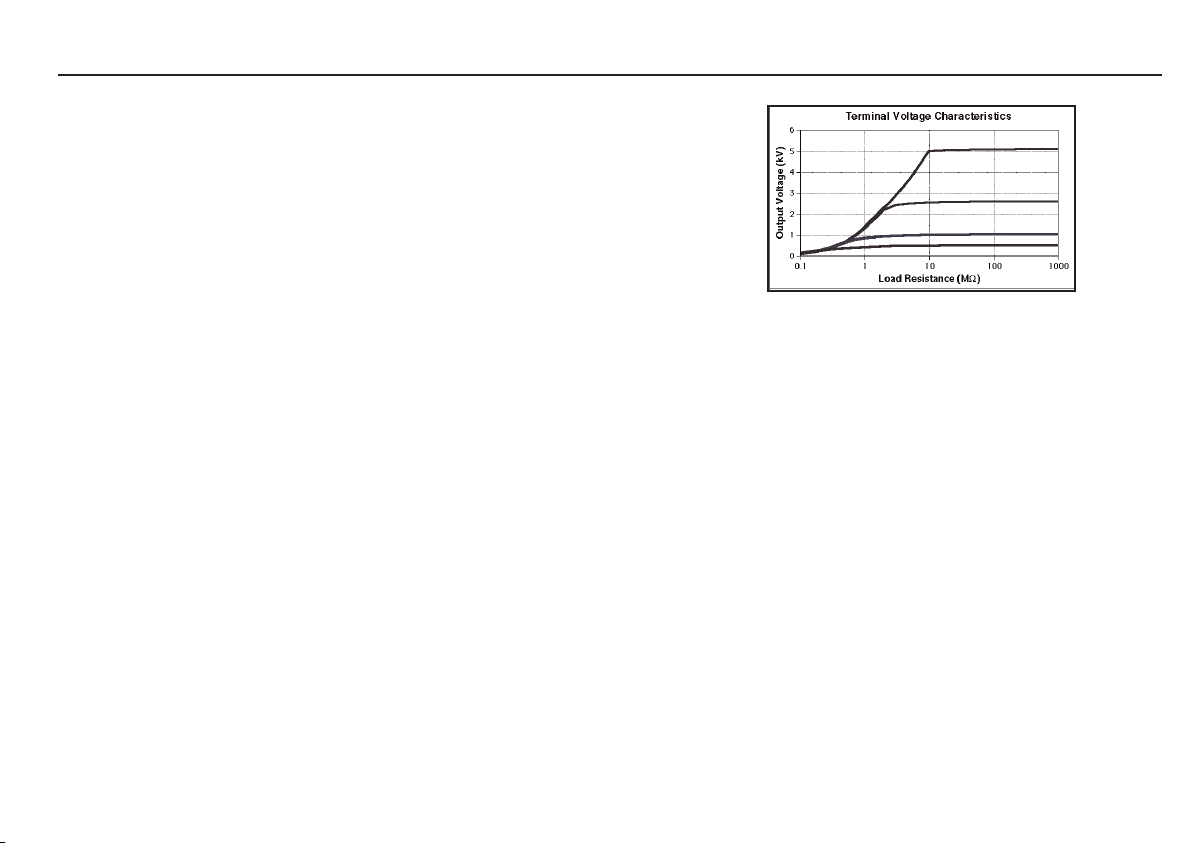
Caracteristiques de la Tension aux Bornes
Tension de Sortie (kV)
Résistance de Charge (MΩ)
22
Page 23

Indicateur des piles: Test de batterie chargée.
Sécurité: Conforme aux exigences de sécurité de double isolement de l’IEC 61010-1 pour une installation de Catégorie III***,
300 volts entre phase et terre (masse) ou 600 volts Catégorie I*.
Fusible non remplaçable: 1 A, 250 V, Type HBC (F) (20 mm x 5 mm) selon IEC 127/1.
Ce fusible protège l’instrument contre toute défaillance lors de l’emploi de piles rechargeables.
Compatibilité électromagnétique: En conformité avec la CEI 61326-1
Incertitudes opérationnelles: visite www.megger.com
Plage de températures: Exploitation : 0˚C à 30˚C à pleine spécification
Exploitation: -20˚C † à 50˚C avec un coefficient de température de ± 0,1%/˚C
Stockage: -25˚C à 65˚C
Humidité: 90% d’humidité relative maximal à 40˚C Dimensions :
Dimensions: 220 mm x 160 mm x 115 mm
Poids: BM15: 1,2 kg environ
MJ15: 1,6 kg ou 1,8 kg avec boîtier de piles et piles
Nettoyage: Essuyer l’instrument déconnecté avec un chiffon propre imbibé d’eau savonneuse ou d’alcool isopropylique (IPA).
***Concerne une surtension transitoire pouvant être rencontrée dans les câblages d’installations fixes.
*Concerne une surtension transitoire pouvant être rencontrée dans les équipements ou parties d’équipements spéciaux, en télécommunications, électronique,
etc.
† Note:
MJ15 fonctionnera normalement avec sa génératrice sur toute la plage de température
BM15 nécessitera de nouvelles piles saines pour fonctionner normalement à -20˚C.
23
Page 24

ACCESSORIES
FOURNI AVEC L’INSTRUMENT NUMERO DE REFERENCE
Guide Utilisateur 6172-209
8 piles de 1,5 V LR6 (AA Alcalines)
Jeu de câbles d’essai, longueur 3 m, (3 câbles sont fournis) 8101-181
Fiches d’enregistrement d’essai (Paquet de 5) 6172-111 (U.S. 210949)
Coffret de transport avec rangement des câbles 6420-117
Transparents de bande passante (5 fournis) 6121-401
DISPONIBLE EN OPTION AVEC SUPPLEMENT
Jeu de sondes 5 kV à fusibles 6320-240
Boîte d’étalonnage 5 kV - CB101 6311-077
Fiches d’enregistrement d’essai (Paquet de 20) 6111-216
PUBLICATIONS
‘A Stitch In Time’ AVTM21-P8B
’Lowdown on HV d.c. Testing’ AVTM22P-1
24
Page 25

RÉPARATION ET GARANTIE
Les circuits de l’instrument contiennent des éléments sensibles à
l’electricite statique et il y a lieu de prendre des précautions en manipulant la
carte de circuits imprimes. Si la protection d’un instrument s’est trouvee
affectée de quelque maniére il ne doit pas être utilisé et doit être expeedié
pour réparation par du personnel convenablement formé et qualifié. La
protection de l’appareil peut s’être trouvée endommagée si par exemple
l’instrument apparaît visiblement abîmee, ne donne pas les performances
attendues, s’est trouvé entreposé de façon prolongée dans des conditions
défavorables ou a été exposé a des contraintes extrêmes durant son transport.
Les nouveaux instruments sont garantis pendant une période
d’un an à partir de la date de leur achat par l’utilisateur.
Note: Le fait d’ouvrir le boîtier annule automatiquement la garantie couvrant
l’instrument à moins que l’opération ne soit faite par un organisme de
réparation agréé
Réparation d’instruments et pièces de rechange
Pour le service des instruments Megger prendre contact soit:
avec ou
Megger Limited Megger
Archcliffe Road Valley Forge Corporate Center
Dover 2621 Van Buren Avenue
Kent CT17 9EN Norristown, PA 19403
Angleterre USA
Tél: + 44 (0) 1304 502243 Tél: +1 (610) 676-8579
Fax: + 44 (0) 1304 207342 Fax: +1 (610) 676-8625
ou avec une societe d’entretien agréée.
Societés d’entretien agréées
Un certain nombre de sociétés indépendantes de reparation d’instruments ont
êté agréées pour faire des opérations de réparation sur la plupart des
instruments Megger utilisant des pièces d’origine Megger. Consultez le
distributeur désigné/agent officiel concernant la fourniture de pièces de
rechange, les installations de réparation et pour être conseillé concernant les
meilleures mesures à prendre.
Renvoi d’un instrument pour le faire réparer
Si un instrument est réexpédiê au fabricant pour être reparé il doit être
envoyé port payé a l’adresse appropriée. Un exemplaire de la facture et la
note d’envoi doivent être envoyé par avion au même moment afin de hâter les
formalités de douane. Un devis estimé des réparations indiquant les frais de
réexpedition et autres frais sera si nécessaire adressé a l’expéditeur avant que
les opérations de réparation ne soient enterprises.
ou
Megger
Z.A. Du Buisson de la Couldre
23 rue Eugène Henaff
78190 TRAPPES
France
Tél: + 33 (1) 43.02.37.54
Fax: + 33 (1) 43.02.16.24
25
Page 26

GEBRAUCHSANLEITUNG - INHALT GUÍA DEL USUARIO - P.38
Sicherheitshinweise 27
Allgemeine Beschreibung 28
Funktionen und Regler 29
Arbeiten mit kapazitiven Belastungen 30
Betrieb
Eingangsprüfungen 31
Wechseln der Batterien 31
Spannungsmessung 32
Isolierprüfung 32
Auswahl der Prüfkabel 32
Verwendung des Schutzanschlusses 33
Technische Daten 34
Zubehör 36
Reparaturen und Garantie 37
Vor Gebrauch des Geräts separate Bedienungsanleitung zum Einbau der
feststellbaren oder nicht feststellbaren Prüftaste beachten. Wenn die
feststellbare Taste eingebaut wird, muß mit besonderer Vorsicht vorgegangen
werden.
Auf Diesem Gérat verwendete Symbole
F Vorsicht Elektroschockgefahr.
G Vorsicht: Bitte beiliegende Anmerkungen beachten.
t Die Anlage ist rundum durch doppelte oder verstärkte
Isolierung (Klasse II) geschutzt.
c Die Anlage entspricht den gegenwärtig gültigen EU-
Direktiven.
26
Page 27

GSICHERHEITSHINWEISE
■ Vor Gebrauch des Geräts müssen die "Sicherheitshinweise" und der Abschnitt "Arbeiten mit kapazitiven Ladungen" gelesen und
verstanden werden. Die Sicherheitshinweise sind beim Bedienen zu beachten.
■ Der geprüfte Stromkreis muß ausgeschaltet, entladen und isoliert werden, bevor die Prüfanschlüsse vorgenommen werden.
■ Die Anschlüsse des Stromkreises dürfen während der Prüfung nicht berührt werden.
■ Nach Abschluß einer Prüfung wird der Spannungsabfall an den Anschlüssen auf der Anzeige dargestellt. Kapazitiv belastete Stromkreise
müssen vor dem Abnehmen der Prüfkabel auf unter 60 V entladen werden.
■ Nach der Entladung müssen die die kapazitiv belasteten Stromkreise mit einer Kurzschlußverbindung kurzgeschlossen werden.
■ Vo r dem Öffnen des Batteriefachs Prüfkabel vom Instrument entfernen.
■ Die Prüfkabel und Krokodilklemmen müssen sich in einem guten Zustand befinden und sauber sein. Die Isolierung darf keine
Bruchstellen oder Risse aufweisen.
■ Gerät nicht verwenden, wenn irgendein Teil von ihm beschädigt ist.
■ Die britischen Sicherheitsbehörden empfehlen den Einsatz von Prüfkabeln mit Sicherungen zur Spannungsmessung bei
Starkstromanlagen. Siehe "Auswahl der Prüfkabel".
ANMERKUNG
dieses instrument dürfen nur von ausreichend geschulten und kompetenten personen bedient werden.
HINWEIS
Die Benutzer dieses Geräts bzw. ihre Arbeitgeber werden daran erinnert, daß bei allen elektrischen Arbeiten eine Gefahrenprüfung stattfinden muß,
um potentielle Gefahren und ein Verletzungsrisiko durch Strom (z. B. bei unbeabsichtigten Kurzschlüssen) zu vermeiden. Wenn sich bei der Prüfung
herausstellt, daß eine bedeutende Gefahr vorliegt, müssen die von den Britischen Sicherheitsbehörden empfohlenen Prüfkabel mit Sicherungen
verwendet werden. Prüfspitzen mit Sicherungen dürfen nicht zur Isolierprüfung eingesetzt werden. Wenn eine Sicherung durchbrennt oder der
Kontakt mit den Prüfspitzen während der Prüfung abreißt, bleibt die geprüfte Anlage geladen, ohne daß die Gefahr bemerkbar wird!
27
Page 28

ALLGEMEINE BESCHREIBUNG
Die Prüfer BM15 und MJ15 sind vollkommen selbständig funktionierende
Geräte zur Überprüfung des Widerstands der Isolierung von
Hochspannungsanlagen, z. B. bei der Wartung und Reparatur von rotierenden
Kraftwerksmaschinen, Transformatoren, Schaltvorrichtungen und
Industrieanlagen.
Die Prüfungen können in einem Bereich von 500 V, 1000 V, 2500 V oder 5000 V
durchgeführt werden. Der Isoliermeßbereich beträgt zwischen 100 kΩ und 20
GΩ oder unendlich. Die geprüften kapazitiven Stromkreise werden
automatisch entladen, der Spannungsabfall angezeigt.
Zur weitgehenden Ausschließung der Auswirkungen von
Oberflächenableitungen kann bei Isolierwiderstandprüfungen ein
Schutzanschluß verwendet werden.
Die Prüfungen werden beim BM15 durch Drücken des Prüftaste (mit der
Beschriftung "Test") und beim MJ15 durch Drehen des Generatorschalters
begonnen. Wenn die Prüftaste losgelassen (bzw. der Drehschalter nicht weiter
gedreht) wird, schaltet das Gerät automatisch in den Modus zur AC/DCSpannungsmessung um, wobei die Anschlüsse intern über einen
Entladewiderstand verbunden sind. Durch diese Funktion läßt sich nach einer
Prüfung von Geräten mit Kapazitanz der Spannungsabfall messen.
Die Messungen werden auf dem Spulenmeßgerät über einen schwarzen Zeiger
auf einer einzelnen logarithmischen schwarzen Skala angezeigt, die auf einem
weißen Hintergrund leicht ablesbar ist. Die Anzeige ist für Außeneinsätze
robust konstruiert.
Über dem Display kann eine Durchgangsschablone eingeschoben werden. Auf
diesen Fenstern lassen sich mit einer permanenten Markierung die jeweiligen
Grenzwertbereiche für eine "Gut / Schlecht"-Prüfung festlegen.
Der BM15wird über acht 1,5 V-Batterien (IEC LR6) versorgt.
Die normale Stromversorgung für den MJ15 erfolgt über einen bürstenlosen
Niederspannungsgenerator mit Handkurbel. Wenn das mitgelieferte
Batteriefach mit acht 1,5 V-Batterien (IEC LR6) gefüllt wird, kann das Gerät auf
zwei Weisen (unabhängig) versorgt werden. Beide Geräte sind mit einer
Batterieprüffunktion ausgestattet, die über die Prüftaste aktiviert wird. Wenn
die Kurbel zu langsam gedreht wird (< 180 U/min), bleibt der Zeiger auf der
Anzeige nicht stabil. Eine zu schnelle Kurbeldrehung wirkt sich auf das Gerät
nicht schädlich aus, da die Ausgangsspannung elektronisch reguliert wird.
Das robuste und zugleich leichte Gehäuse ist aus flammenhemmenden ABS
hergestellt und besitzt ein Anzeigefenster aus Polycarbonat. Auf der Oberseite
des Gehäuses befinden sich ein Drehschalter zur Bereichsauswahl mit 6
Stellungen und die Prüftaste.
Die drei vertieften Buchsen sind mit "+", "-" und "G" gekennzeichnet. Die
Buchsen sind mit Sicherheitsabdeckungen versehen, welche sich beim
Einschieben der Stecker öffnen. Wenn die abgeschirmten Stecker der
Prüfkabel in die Buchsen eingesteckt werden, rasten sie in der richtigen
Position ein. Die Stecker werden gelöst, indem sie eine Viertelumdrehung
gedreht und herausgezogen werden.
Wegen dieser Eigenschaften sollten nur die mitgelieferten Prüfkabel oder
geeignete Ersatzkabel von MEGGER® verwendet werden.
Zu den Sicherheitsvorkehrungen gehören die folgenden
Eigenschaften:
■ Angezeige der externen AC- oder DC-Spannung.
■ Automatische Entladung nach der Prüfung, Spannungsabfall wird
angezeigt.
■ Die Prüfkabel rasten im Prüfanschluß des Gehäuses ein, so daß eine
unbeabsichtigte Trennung verhindert wird.
28
Page 29

FUNKTIONEN UND REGLER
Drehwählschalter
Nicht feststellbare
Prüftaste
(empfohlene Option)
Generatorschalter (MJ15)
Feststellbare
Prüftaste (bei
Verwendung dieser
Option muß mit
besonderer Vorsicht
vorgegangen
werden)
- Anschluß
Schutzpol
+ Anschluß
ANSCHLUßSTECKER ZUM EINFÜHREN HINEINSCHIEBEN UND ZUM LÖSEN EINE
VIERTELUMDREHUNG DREHEN UND HERAUSZIEHEN.
29
Page 30

ARBEITEN MIT KAPAZITIVEN BELASTUNGEN
G
Die Anschlüsse von Stromkreis und Gerät können bei
Verbindung mit kapazitiven Belastungen gefährlich werden.
1. Mit diesem Gerät können Belastungen von bis zu 5 µF gefahrlos
geladen und entladen werden. Zum Schutz vor Defekten empfiehlt es
sich jedoch, beim Arbeiten mit kapazitiven Belastungen besondere
Vorsichtsmaßnahmen vorzunehmen. Selbst Kondensatoren mit
geringen Werten können bei Berührung tödlich sein.
2. Wenn die feststellbare Prüftaste verwendet wird, muß besonders
vorsichtig vorgegangen werden.
3. Die Anschlüsse des Stromkreises dürfen bei der Prüfung nicht berührt
werden.
Eine festgestellte Prüftaste muß unbedingt wieder gelöst und
die gesamte Kapazitanz entladen werden, bevor der geprüfte
Gegenstand berührt oder die Prüfkabel getrennt werden.
4. Kapazitive Stromkreise dürfen bei der Prüfung nicht unterbrochen
werden, da sie sonst geladen bleiben.
5. Nach Abschluß einer Prüfung wird der Spannungsabfall des
Stromkreises auf der Anzeige dargestellt. Prüfkabel erst abnehmen,
wenn die Belastungskapazitanz auf unter 60 V gesunken ist.
6. Die Spannungmesser- und automatische Entladefunktion des Geräts
dienen zur zusätzlichen Sicherheit und ersetzen keinesfalls die
üblichen Vorsichtsmaßnahmen bei der Arbeit.
7. Wenn ein Teil des Prüfgeräts beschädigt ist, darf das Gerät nicht
verwendet werden, sondern ist zur Reparatur an eine autorisierte
Wartungsniederlassung zu senden.
30
Page 31

BETRIEB
Eingangsprüfungen
Das Gerät funktioniert zwar in jeder Stellung, liefert jedoch die besten
Ergebnisse, wenn die Vorderseite nach oben zeigt und das Gerät auf einer
festen und ebenen Unterlage steht. Dies gilt insbesondere für Geräte mit
Handkurbel, weil auf diese Weise leichter die benötigte konstante
Kurbeldrehzahl von > 180 U/min erreicht wird.
1. Wenn Batterien eingesetzt sind, auf Batterieprüfung stellen und die
‘Test‘ (Prüftaste) drücken. Prüfen, ob der Zeiger auf das
Batteriesymbol der Skala zeigt.
2. Bei getrennten Prüfkabeln Drehschalter auf den passenden
Isolierbereich stellen und ‘Test‘ (Prüftaste) drücken und festhalten
(bzw. Generatorschalter drehen). Der Meßzeiger sollte sich auf der
Skala kurz nach oben bewegen und anschließend auf die Position "∞"
(unendlich) der Skala zeigen. Durch diese Prüfung wird sichergestellt,
daß keine Oberflächenableitung über das Gerät stattfindet.
3. Sicherstellen, daß die Prüfkabel und Krokodilklemmen sauber und
intakt sind und die Isolierung keine Risse oder Schäden aufweist. Zwei
Prüfkabel an den "+"- und "-" -Polen anschließen und darauf achten,
daß die Klemmen nichts anderes berühren.
4. Prüftaste erneut drücken (bzw. Generatorschalter drehen) und
Meßzeiger beobachten. Der Zeiger sollte auf die Position "∞“
(unendlich) der Skala zeigen. Ist dies nicht der Fall, so sind evtl. die
Prüfkabel defekt. Kabel genau untersuchen und ggf. erneuern.
5. Klemmen der Prüfkabel miteinander verbinden, ‘Test‘ (Prüftaste)
drücken (bzw. Generatorschalter drehen) und Meßzeiger beobachten.
Der Zeiger sollte auf "0Ω" stehen. Wenn ein unendlicher oder sehr
hoher Widerstandswert dargestellt wird, ist evtl. der Stromkreis der
Prüfkabel unterbrochen. Kabel genau untersuchen und ggf. erneuern.
(Das Gerät kann auch überprüft werden, indem die Kabel
kurzgeschlossen werden; wenn "0Ω" angezeigt werden, ist die
Funktion in Ordnung.)
Wechseln der Batterien
GWARNING
Die Batteriekontakte sind nicht von den Prüfkabeln isoliert. Vo r dem
Öffnen des Batteriefachs müssen die Prüfkabel daher vom Instrument
getrennt werden. Die Batterien befinden sich im Batteriefach an der
Unterseite des Geräts.
Zum Wechseln der Batterien Befestigungsschrauben des Batteriefachs mit
Schraubenzieher entfernen und Abdeckung des Batteriefachs abheben.
8 neue IEC LR6 Batterien (Mignonzellen) unter Beachtung der Polarität
einsetzen. Anschließend Abdeckung des Batteriefachs wieder einsetzen und
befestigen.
31
Page 32

BETRIEB
Spannungsmessung
Wenn das Gerät auf "V" geschaltet wird, mißt es Spannungen bis zu 600 V AC
mit der angegebenen Genauigkeit. Auch Gleichstrom kann auf der Anzeige
dargestellt werden, allerdings nicht mit der angegebenen Genauigkeit. Wenn
das Gerät an einen spannungsführenden Stromkreis angeschlossen ist und
momentan nicht zur Prüfung verwendet wird (Standby-Betrieb), funktioniert
es unabhängig von der Stellung des Drehschalters automatisch als Voltmeter
(0 bis 600 V AC oder DC). Jede vorhandene Spannung wird sofort dargestellt,
so daß sofort bemerkbar wird, wenn ein Gegenstand noch nicht vollständig
entladen wurde. Bei der Isolierprüfung eines kapazitiven Gegenstands, z. B.
eines langen Kabels, überwacht das Gerät auch die Entladung des
Stromkreises nach Loslassen der Test (Prüftaste).
Isolierprüfung
Wenn die Prüfkabel am Instrument angeschlossen und die Eingangsprüfungen
beendet sind:
1) Wählschalter auf die gewünschte Prüfspannung stellen. Prüfkabel wie
folgt an den zu prüfenden Stromkreis anschließen:
a) Zur Isolierprüfung an Erde (Masse): Ein Prüfkabel an
Masse oder das Gerätgehäuse und das andere Kabel an
den zu prüfenden Stromkreis anschließen.
b) Zur Isolierprüfung zwischen Kabeln: Jeweils ein Kabel an
den Draht jedes Kabels anschließen.
2) Prüftaste drücken (bzw. Generatorschalter drehen).
3) Der Meßzeiger zeigt den Wert des Isolierwiderstands auf der Ω Skala
an.
Wenn ein kapazitiver Stromkreis getestet wird, sinkt der Zeiger zunächst gegen
0 Ω. Während des Aufladens der Kapazitanz bis auf den Wert der
Ausgangsspannung des Prüfers steigt der Zeiger dann allmählich an und bleibt
schließlich auf einem konstanten Wert stehen.
Wenn mehrmals hintereinander ein Wert von ∞ (unendlich) angezeigt wird,
müssen die beiden äußeren Enden der Prüfkabel miteinander verbunden und
die Kabel überprüft werden. Wenn ein Wert von 0Ω angezeigt wird, kann mit
Sicherheit davon ausgegangen werden, daß die Kabel nicht getrennt oder
beschädigt sind und der angezeigte Wert des Isolierwiderstands stimmt.
Nach Loslassen der Prüftaste werden kapazitive Stromkreise vom Prüfgerät
automatisch entladen. Der Spannungsabfall wird auf der Spannungsskala
angezeigt. Vor dem Trennen der Prüfkabel muß die Spannung auf unter 60 V
gesunken sein.
Auswahl der Prüfkabel
Eine festgestellte Prüftaste muß unbedingt wieder gelöst und
die gesamte Kapazitanz entladen werden, bevor der geprüfte
Gegenstand berührt oder die Prüfkabel getrennt werden.
Der BM15 und der MJ15 werden mit drei Kabeln ohne Sicherung geliefert, die
mit Krokodilklemmen versehen sind. Diese Kabel sind optimal für
Isolierprüfungen bei nicht spannungsführenden Stromkreisen. Durch die
Krokodilklemmen wird sichergestellt, daß die kapazitive Belastung so lange
angeschlossen bleibt, bis sie nach der Prüfung automatisch entladen wird.
Die britischen Sicherheitsbehörden empfehlen zur Spannungsmessung bei
Starkstromanlagen den Einsatz von Prüfkabeln mit Sicherungen. Diese Kabel
sind als Sonderzubehör erhältlich. Siehe "Zubehör".
Prüfspitzen mit Sicherungen dürfen nicht zur Isolierprüfung eingesetzt
werden. Wenn die Sicherung durchbrennt oder der Kontakt mit den
Prüfspitzen während der Prüfung abreißt, bleibt die geprüfte Anlage geladen,
ohne daß die Gefahr bemerkbar wird!
32
Page 33

Verwendung des Schutzanschlusses (G)
Für einfache Isolierprüfungen und für Prüfungen, bei denen nicht zu erwarten
steht, daß die Messung durch Oberflächenableitung beeinflußt wird, braucht
der Schutzanschluß nicht verwendet zu werden (sofern die Isolierung sauber
ist und störende Strömungspfade unwahrscheinlich sind). Bei der Prüfung von
Kabeln kann jedoch aufgrund von Feuchtigkeit oder Schmutz durch die
Isolierung hindurch eine Oberflächenableitung zwischen dem blanken Kabel
und der äußeren Hülle auftreten. Um den Effekt dieser Ableitung
auszuschalten, sollte insbesondere bei hohen Prüfspannungen die Isolierung
fest mit einem blanken Draht umwickelt und über das dritte Prüfkabel mit
dem Schutzanschluß "G" verbunden werden.
Der Schutzanschluß besitzt dasselbe Potential wie der Minuspol. Da der
Widerstand des Kriechstroms zu dem gemessenen Widerstand effektiv parallel
verläuft, wird durch den Schutzanschluß der von der Oberflächenableitung
verursachte Kriechstrom vom gemessenen Stromkreis weggeleitet. Da Gerät
zeigt daher nur den Kriechverlust des Isolators an und ignoriert den durch
Oberflächenableitung verursachten Kriechverlust.
Pfad des
Kriechstroms
zum
Anschluß
"+" ve
zum
Anschluß
"G"
Fest umwickelter
blanker Draht
zum
Anschluß
"-" ve
BETRIEBS-BLOCKSCHALTBILD
33
Page 34

TECHNISCHE DATEN
Isolierung
Bereich: 100 kΩ bis 20 GΩ (auch 0Ω und ∞ )
Prüfspannung (DC): 500 V, 1000 V, 2500 V oder 5000 V
Genauigkeit der Prüfspannung: ± 5% der nominalen Prüfspannung bei einer Belastung von 20 MΩ
Stabilität der Prüfspannung: < ± 1% (180 U/min bis 240 U/min - MJ15)
Isoliergenauigkeit (bei 0 - 30˚C): ±2,5 % des Zeigerausschlags
Kurzschlußstrom: 1,5 mA ± 0,5 mA
Maximale Kapazitanz der Ladung: 5 µF
Störschutz: effektiver Mittelwert: 1 mA bei 50 - 60 Hz
Entladewiderstand: < 500 kΩ
Spannung
Bereich: 0 - 600 V AC, DC wird angezeigt
Genauigkeit: ± 2,5 % bei vollem Zeigerausschlag (Drehschalter in Stellung V) ± DC ohne Angaben
Allgemein
Größte Nutzlast: 720 V AC oder DC
Skalenlänge: 72 mm (96˚)
Stromversorgung: BM15: 8 x LR6 Alkali-Mignonbatterien oder Akkubatterie
MJ15: Bürstenloser Niederspannungsgenerator oder 8 x LR6 Alkali-Mignonbatterien
Haltbarkeit der Batterien: In der Regel 2000 Prüfungen von je 5 Sekunden Dauer bei einer Belastung von 100 MΩ
Batterieanzeige: Überprüfung der Batterieladung
Eigenschaften der Anschlußspannung
Ausgangsspannung (kV)
Lastwiderstand (MΩ)
34
Page 35

Sicherheit: IEC 61010-1
Nicht erneuerbare Sicherungen: 1 A, 250 V, HBC-Art (F) (20 mm x 5 mm) nach IEC 127/1
AllgemeinElektromagnetische Störfreiheit: IEC 61326-1
Betriebliche Unklarheiten: Besuch www.megger.com
Temperaturbereich: Betrieb: 0˚C bis 30˚C bei voller Einhaltung der Spezifikationen
Betrieb: -20˚C † bis 50˚C bei einem Temperaturkoeffizienten von ± 0,1 % / ±C
Lagerung: -25˚C bis 65˚C
Feuchtigkeit: 90 % relative Luftfeuchitgkeit bei 40˚C
Maße: 220 mm x 160 mm x 115 mm
Gewicht: BM15: ca 1,2 kg
MJ15: ca 1,6 kg oder 1,8 kg mit Batteriehalter und Batterien
Reinigung: Anschlüsse des Geräts trennen und Gerät mit sauberem Tuch und Seifenwasser oder
Isopropylalkohol (IPA) abwischen.
*** bezieht sich auf eine Stoßspannung, die bei der Verkabelung von fest installierten Geräten auftreten kann
* bezieht sich auf eine Stoßspannung, die bei Spezialgeräten, Geräteteilen, Fernmelde- oder elektronischen
Anlagen usw. auftreten kann
† Hinweis: Der MJ15 arbeitet im gesamten Temperaturbereich bei Generatorbetrieb normal Der BM15 benötigt für einen
Normalbetrieb bei -20˚C frische Batterien.
35
Page 36

ZUBEHÖR
MIT DEM GERÄT GELIEFERT TEILENUMMER
Gebrauchsanleitung 6172-209
2 x 1,5 V LR6 Alkali-Mignonbatterien
Prüfkabelsatz aus 3 Kabeln, Länge 3 m 8101-181
Karten (5 Stück) zum Notieren der Prüfdaten 6172-111 (U.S. 210949)
Tragekoffer mit Stauraum für Kabel 6420-117
Einschiebbare Durchgangsschablonen (5 Stück) 6121-401
SONDERZUBEHÖR
5 kV Prüfspitzensatz mit Sicherung 6320-240
5 kV Kalibrierbox - CB101 6311-077
Karten zum Notieren der Prüfdaten (20 Stück) 6111-216
Publikationen
‘A Stitch In Time’ AVTM21-P8B
’Lowdown on HV d.c. Testing’ AVTM22P-1
36
Page 37

REPARATUREN UND GARANTIE
Das Instrument enthält statisch empfindliche Bauteile, weshalb die gedruckte
Schaltung sorgfältig behandelt werden muß. Falls die Schutzvorrichtungen
eines Instruments beschädigt worden sind, sollte es nicht verwendet, sondern
an eine geeignete Reparaturwerkstatt geschickt werden. Die
Schutzvorrichtungen sind wahrscheinlich beschädigt, wenn folgende
Bedingungen vorliegen: sichtbare Beschädigung, fehlende Anzeige der
erwarteten Meßergebnisse; längere Lagerung unter widrigen Bedingungen
oder starke Transportbelastung.
NEUE INSTRUMENTE UNTERLIEGEN EINER GARANTIE VON 1 JAHR
AB DEM DATUM DES KAUFS DURCH DEN BENUTZER.
Hinweis: Das Gehäuse darf nur von entsprechend autorisierten
Reparaturfirmen geöffnet werden, da sonst die Garantie für dieses Instrument
automatisch erlischt.
Reparaturarbeiten und Ersatzteile
Wenden Sie sich zwecks Wartungsarbeiten an Megger-lnstrumenten entweder
an:
Megger Limited oder Megger
Archcliffe Road Valley Forge Corporate Center
Dover 2621 Van Buren Avenue
Kent CT17 9EN Norristown, PA 19403
England USA
Tél: + 44 (0) 1304 502243 Tél: +1 (610) 676-8579
Fax: + 44 (0) 1304 207342 Fax: +1 (610) 676-8625
Autorisierte Reparaturfirmen
Eine Reihe von Firmen sind für die Reparatur der meisten Meggerlnstrumente unter Verwendung von Original Megger-Ersatzteilen autorisiert.
Wenden Sie sich wegen Ersatzteilen, Reparaturwerkstatten und Beratung über
die jeweils bestgeeigneten Maßnahmen an eine autorisierte Auslieferung bzw.
Vertretung.
Einsenden Eines Instruments Zur Reparatur
Wenn ein Instrument zwecks Reparatur zurück geschickt werden muß, sollte
es mit vorbezahiter Fracht an die angebrachte Anschrift gesandt werden.
Gleichzeitig sollte zur Erledigung der britischen Zollformalitäten per Luftpost
eine Kopie der Rechnung zusammen mit dem Packzettel eingesandt werden.
Auf Wunsch wird dem Absender vor Ausführung irgendwelcher Arbeiten am
Instrument ein Kostenvoranschlag unter Berücksichtigung der Frachtkosten
und anderer Gebühren zugesandt.
oder an eine autorisierte Reparaturfirma.
37
Page 38

GUÍA DEL USUARIO - CONTENIDO
Avisos de Seguridad 39
Descripción General 40
Características y Controles 41
Trabajo con cargas capacitivas 42
Funcionamiento
Comprobaciones preliminares 43
Recambio de las pilas 43
Medición de voltaje 44
Prueba de aislamiento 44
Elección de conductores de prueba 44
Uso del borne de protección 45
Especificaciones 46
Accesorios 48
Reparación y Garantía 49
Antes de usar el instrumento, observe las instrucciones separadas incluidas
para instalar el botón de prueba ya sea bloqueable o bien no bloqueable. Si se
instala el botón bloqueable, Deben adoptarse precauciones adicionales.
Símbolos usados en el instrumento
F Riesgo de sacudida eléctrica.
G Referirse a la Guía del Usuario.
t Equipo totalmente protegido por aislamiento
doble (Clase II).
c El equipo está conforme con las directrices
actuales de la UE.
38
Page 39

GAVISOS DE SEGURIDAD
■ Las secciones 'Avisos de seguridad' y 'Trabajando con cargas capacitivas' deben ser leídas y comprendidas antes de
usar el instrumento. Las precauciones de seguridad deben ser observadas durante el uso.
■ El circuito en prueba debe ser desconectado, desenergizado y aislado antes de efectuar conexiones de prueba.
■ Las conexiones del circuito no deben tocarse durante la prueba.
■ Al finalizar la prueba se indica en la pantalla el voltaje decreciente que fluye a través de los bornes. Los circuitos de
carga capacitiva deben ser descargados a menos de 60V antes de desconectar los conductores de prueba.
■ Los circuitos de carga capacitiva deben ser conectados a tierra con una conexión de cortocircuitar después de la descarga.
■ Retire los conductores de prueba del instrumento antes de abrir el compartimiento de las pilas.
■ Los conductores de prueba y los clips de mandíbulas deben estar en buen estado de servicio, limpios y con el
aislamiento intacto.
■ El instrumento no debe ser usado si cualquier parte está dañada.
■ Las autoridades de seguridad del Reino Unido recomiendan usar conductores de prueba provistos de fusibles cuando se
mide el voltaje en sistemas de alta energía. Vea 'Elección de conductores de prueba'.
NOTA
EL INSTRUMENTIO SOLO SERA UTILIZADO POR PERSONAS CAPACITADAS Y COMPETENTES.
NOTA
Se recuerda a los usuarios de este equipo, o sus empleados, que deben llevar a cabo evaluaciones válidas de riesgo en todo el trabajo
eléctrico a fin de identificar los posibles puntos de peligro eléctrico que pueden resultar en lesiones para el personal a causa de
cortocircuitos, por ejemplo. Si las evaluaciones muestran que el riesgo es significativo, deberán usarse conductores de prueba provistos
de fusibles como recomiendan las autoridades de seguridad del Reino Unido. No se deben usar sondas provistas de fusibles para la prueba
de aislamiento. Si se funde el fusible, o si las sondas pierden su contacto durante una prueba, el sistema en prueba debería permanecer
cargado ¡sin ninguna señal de peligro aparente!
39
Page 40

DESCRIPCIÓN GENERAL
Los probadores BM15 y MJ15 son instrumentos completamente autónomos
diseñados para efectuar pruebas de resistencia de aislamiento de alto voltaje
en el mantenimiento y servicio de maquinaria giratoria, transformadores,
mecanismos de conmutación e instalaciones industriales.
Las pruebas pueden ser realizadas a 500, 1000, 2500 ó 5000 voltios de manera
seleccionable. La gama de mediciones de aislamiento es de 100 kΩ a 20 GΩ e
infinidad. Se incluye descarga automática para circuitos capacitivos y se
visualiza el voltaje decreciente.
Puede usarse un borne de protección para reducir al mínimo los efectos de la
fuga superficial cuando se realizan pruebas de resistencia del aislamiento.
Las pruebas se inician pulsando el botón de prueba ('Test') BM15 (o girando la
manivela del generador MJ15). Al soltar el botón 'Test' (o dejar de girar la
manivela), el instrumento pasará por defecto al modo de voltímetro ca/cc, con
un resistor de descarga conectado internamente entre los bornes. Esta
característica aportará una indicación de voltaje decreciente seguido de la
prueba del equipo que posee la capacitancia.
El medidor de cuadro móvil acciona una aguja indicadora negra que visualiza
las lecturas en una escala negra logarítmica sencilla situada sobre una placa
con escala blanca para ofrecer mayor claridad de la lectura. El conjunto móvil
está montado sobre una base resistente para uso en pie de obra.
Puede insertarse sobre la visualización una diapositiva superpuesta sobre la
banda de pasa. Pueden trazarse en estas ventanas bandas de pasa/falla con un
marcador indeleble para la pruebas de tolerancia máxima y mínima. El BM15
funciona con ocho pilas de 1,5 V (IEC RL6).
La potencia normal requerida por el MJ15 la desarrolla un generador de c.a.
sin escobillas, de giro manual y bajo voltaje. Colocando en el recipiente de la
batería suministrado ocho pilas de 1,5 V IEC RL6, se aporta al instrumento una
capacidad de suministro doble (independiente). Ambos instrumentos
incorporan una gama de comprobación de batería, la cual funciona al pulsar el
botón 'Test'. Si se gira la manivela con demasiada lentitud (<180 rpm), la
lectura de la aguja indicadora será inestable. Una velocidad excesiva de la
manivela no podrá dañar el instrumento porque el voltaje de salida está
regulado de modo electrónico.
La caja es robusta, pero liviana, fabricada con un ABS pirorretardante, e
incorpora una ventana de visualización de policarbonato. Montado en la parte
superior de la caja hay un interruptor selector de gama giratorio de 6
posiciones, así como un botón pulsador de prueba ('Test').
Se incluyen tres tomas en rebaje marcadas '+', '-' y 'G'. Estos interruptores
tienen cubiertas de seguridad que se abren cuando se insertan los enchufes.
Una vez insertados en sus tomas, los enchufes de los conductores de prueba
cubiertos quedan bloqueados en su posición. Se sueltan girando el conductor
un cuarto de vuelta y tirando del mismo para desenchufarlo.
Por este motivo solamente deberán usarse los conductores de prueba
suministrados o repuestos Megger adecuados.
Las características de seguridad incluidas son:
■ Visualización externa de voltaje c.a. o c.c.
■ La carga se descarga automáticamente al final de la prueba, y se
visualiza el voltaje decreciente visualizado.
■ Los conductores de prueba se bloquean en sus tomas en la caja para
prevenir una desconexión accidental.
40
Page 41

CARACTERÍSTICAS Y CONTROLES
Interruptor selector
giratorio
Botón
no bloqueable
(opción
recomendada)
Manivela de generador (MJ15)
Botón bloqueable
(debe adoptarse
precaución
adicional si se
selecciona esta
opción)
Borne -
Borne de protección
Borne +
PARA INSERTAR LOS ENCHUFES DE LOS BORNES, EMPÚJENSE ESTOS; PARA SOLTARLOS GÍRENSE UN
CUARTO DE VUELTA Y TÍRENSE DE ELLOS PARA SACARLOS.
41
Page 42

TRABAJO CON CARGAS CAPACITIVAS
G
Las conexiones del circuito y los bornes del instrumento
pueden resultar peligrosos si se conectan a cargas capacitivas.
1. Estos instrumentos están diseñados para cargar y descargar con
seguridad cargas capacitivas de hasta 5 µF. No obstante, para
asegurarse contra un mal funcionamiento, se aconseja adoptar
precauciones propias cuando se trabaja con cargas capacitivas.
Recuérdese que cuando están cargados, incluso los capacitores de bajo
valor pueden resultar fatales a su contacto.
2. Debe adoptarse precaución adicional si se selecciona el botón de
prueba ('Test') bloqueable.
3. Las conexiones del circuito no deben tocarse durante la prueba.
No se olvide de soltar el botón de prueba bloqueado, y de
descargar cualquier capacitancia antes de tocar el aparato en
prueba, o de desconectar los conductores de prueba.
4. Debe tenerse cuidado de impedir que sean desconectados los circuitos
capacitivos durante la prueba, dejando el circuito cargado.
5. Al finalizar la prueba, el instrumento indica un voltaje decreciente. No
desconecte los conductores de prueba hasta que la capacitancia de
carga se haya descargado a menos de 60 V.
6. El voltímetro y la descarga automática del instrumento deberán
considerarse como características de seguridad adicionales, no como
sustitutos para la práctica normal de trabajo seguro.
7. Si cualquier parte del instrumento está dañada, éste no deberá ser
usado sino que deberá ser devuelto al fabricante o a una empresa de
servicio aprobada para su reparación.
42
Page 43

FUNCIONAMIENTO
Comprobaciones de ejecución preliminares
El instrumento funcionará en cualquier posición, pero los mejores resultados
se obtienen cuando el instrumento está boca arriba, situado sobre una
superficie firme nivelada. Esto es especialmente aplicable en aparatos
accionados por manivela para obtener una velocidad de giro de manivela
constante y uniforme de >180 rpm.
1. Si se incorporan pilas de batería, conmute a gama de comprobaciones
de batería y pulse el botón de prueba ('Test'). Asegure que la aguja
indicadora asienta dentro de la parte de la escala donde aparece el
símbolo de la batería.
2. Con los conductores de prueba desconectados, fije el interruptor
selector giratorio en la gama de aislamiento apropiada, pulse y retenga
el botón de prueba (o gire la manivela del generador). La aguja
indicadora deberá moverse un poco hacia arriba de la escala y luego
retornar a la posición '∞ ' (infinidad) de la escala. Con esto se establece
que no hay fugas por el propio instrumento.
3. Asegure que los conductores de prueba y los clips de mandíbula están
en buen estado de servicio, limpios y con su aislamiento intacto.
Conecte dos de los conductores de prueba en los bornes '+' y '-' y
asegure que sus clips no estén en contacto con nada.
4. Pulse otra vez el botón de prueba (o gire la manivela del generador) y
observe la aguja indicadora del medidor. La aguja deberá descansar
sobre la posición '∞ ' de la escala. En caso contrario, los conductores
de prueba pueden estar defectuosos y deberán ser inspeccionados con
más detenimiento por si tienen daños. Recambie los conductores si es
necesario.
5. Conecte los clips del conductor de prueba, pulse el botón de prueba (o
gire la manivela del generador) y observe la aguja indicadora del
medidor. El medidor debe mostrar '0 Ω'. Si indica infinidad o un alto
valor de resistencia, los conductores pueden estar en circuito abierto y
deberán inspeccionarse con mayor detenimiento. Recambie los
conductores si es necesario. (Si se cortocircuitan los conductores y se
obtiene una lectura '0 Ω', esto también indicará que el instrumento está
funcionando.
Recambio de la batería
GAVISO
Los contactos de la batería no están aislados de los conductores de
prueba. Retire los conductores de prueba del instrumento antes de abrir
el compartimiento de las pilas. Las pilas están alojadas en su compartimiento
en la base del instrumento.
Para cambiar las pilas, quite con un destornillador los tornillos de sujeción de
la tapa de la batería y saque la tapa del compartimiento de la batería.
Observando la correcta polaridad marcada en el alojamiento de la batería,
instale las 8 pilas IEC RL6 (AA) de repuesto. Al finalizar esta operación,
reinstale y sujete la tapa del compartimiento de la batería.
43
Page 44

FUNCIONAMIENTO
Medición del voltaje
Cuando se conmuta a la posición 'V', el instrumento mide hasta 600 V c.a. de
acuerdo con la precisión especificada del instrumento. El voltaje c.c. también
es visualizado, pero no de acuerdo con la precisión especificada. Cuando no
se hacen pruebas con el instrumento (i.e. está en la función de espera) y está
conectado a un circuito nergizado, pasará por defecto a la función de
voltímetro (de 0 a 600 voltios c.a. o c.c.) sin tener en cuenta la posición del
interruptor giratorio. Cualquier voltaje presente será visualizado
inmediatamente. Así pues, el instrumento indica que el elemento no ha sido
totalmente desenergizado. El instrumento también supervisa la descarga del
circuito cuando se suelta el botón de prueba después de una prueba de
aislamiento en un elemento capacitivo, e.g. un cable largo.
Pruebas de aislamiento
Después de conectar los conductores de prueba al instrumento, y de realizar
las comprobaciones de ejecución preliminares:
1. Sitúe el interruptor selector en el voltaje de prueba requerido.
Conecte los conductores de prueba al circuito aislado que se desea
probar, como sigue:
a) Para pruebas de aislamiento a tierra (masa): Conecte uno de los
conductores de prueba a tierra (masa) o a la estructura del
equipo, y el otro conductor a la parte del circuito que se desea
probar.
b) Para pruebas de aislamiento entre hilos: Conecte el conductor al
núcleo de cada uno de los hilos.
2. Pulse el botón de prueba (o gire la manivela del generador).
3. La aguja indicará el valor de la resistencia del aislamiento en la escala
de Ω. Si se prueba un circuito capacitivo, la aguja se desviará
inicialmente hacia 0 Ω y luego ascenderá gradualmente hasta su valor
uniforme definitivo a medida que la capacitancia es cargada hasta el voltaje de
salida del probador.
Si se obtienen varias lecturas de '∞ ' (infinidad) sucesivas, conecte juntos los
extremos más alejados de los conductores de prueba y compruebe éstos.
Deberá obtenerse una lectura de 0 Ω con lo cual se confirma de nuevo que los
cables no están desconectados o rotos, y que son correctas las lecturas de
resistencia del aislamiento.
Los circuitos capacitivos son descargados automáticamente a través del
probador cuando se suelta el botón de prueba ('Test'). El voltaje decreciente
será indicado en la escala de voltajes. Espere un poco para que el voltaje
disminuya por debajo de 60V antes de desconectar los conductores de prueba.
No se olvide de soltar el botón de prueba bloqueado, y de
descargar cualquier capacitancia antes de tocar el aparato en
prueba, o de desconectar los conductores de prueba.
Elección de conductores de prueba
Los instrumentos BM15/MJ15 se envían con tres conductores sin fusibles
rematados en clips de mandíbulas. Estos son los mejores conductores que
pueden usarse en circuitos desenergizados. Los clips de mandíbulas aseguran
que la carga capacitiva permanezca conectada hasta que descargarse
automáticamente al finalizar la prueba.
Las autoridades de seguridad del Reino Unido aconsejan usar sondas de
prueba provistas de fusibles si el instrumento se va a usar para la medición de
circuitos energizados de alta energía. Estos conductores se ofrecen disponibles
como extras opcionales. Vea 'Accesorios'.
No se deben usar sondas provistas de fusibles para la prueba de aislamiento. Si
se funde el fusible, o si las sondas pierden su contacto durante una prueba, el
sistema en prueba debería permanecer cargado ¡sin ninguna señal de
44
Page 45

peligro aparente!
Uso del borne de protección (G)
Para pruebas de aislamiento básico y donde hay poca posibilidad de que la
fuga superficial afecte la medición, no es necesario usar el borne de
protección (si el aislador está limpio y es poco probable que haya trayectos de
corriente adversos). No obstante, en la prueba de cables puede haber
trayectos de fuga superficial a través del aislamiento entre el cable desnudo y
la vaina externa debido a la presencia de humedad o suciedad. Donde se
requiere neutralizar el efecto de esta fuga, particularmente a altos voltajes de
prueba, puede disponerse un hilo desnudo alrededor del aislamiento y
conectarse vía el tercer conductor de prueba al borne de protección 'G'.
El borne de protección tiene la misma capacidad que el borne negativo. Como
la resistencia de fuga es efectivamente paralela con la resistencia que se desea
medir, el uso del borne de protección hace que el flujo de corriente a través
de la fuga superficial se desvíe del circuito de medición. Así pues, el
instrumento registra la fuga del aislador, ignorando la fuga a través de su
superficie.
Trayecto de la fuga
Al borne
`+`
Al borne
`G`
Hilo desnudo atado con seguridad
Al borne
`-`
DIAGRAMA ESQUEMÁTICO DEL FUNCIONAMIENTO
45
Page 46

ESPECIFICACIONES
Aislamiento
Gama: de 100 kΩ a 20 GΩ (también 0Ω y ∞ )
Voltajes de prueba (c.c.): 500, 1000, 2500 y 5000 voltios
Precisión del voltaje de prueba: ±5% de los voltajes de prueba nominales en carga de 20 MΩ.
Estabilidad del voltaje de prueba: ±1% (de 180 a 240 rpm - MJ15)
Precisión del aislamiento (a 0 - 30ºC): ± 2,5% de desviación máxima
Corriente de cortocircuito: 1,5 mA ± 0,5 mA
Máxima capacitancia de carga: 5 µF
Rechazo de interferencia: 1mA rms de 50 a 60Hz
Resistor de descarga: <500 kΩ
Voltaje
Gama: de 0 a 600 V c.a. indicación de c.c.
Precisión: ± 2,5% de desviación máxima (con el interruptor giratorio en la posición V) ± c.c. no especificada
Generalidades
Capacidad de sobrecarga: 720 V c.a. o c.c.
Longitud de la escala: 72 mm (96˚)
Suministro eléctrico:
BM15: 8 pilas tipo LR6 (alcalinas AA)
MJ15: Generador sin escobillas de bajo voltaje u 8 pilas tipo LR6 (alcalinas AA)
Duración de la batería: Normalmente 2000 pruebas de cinco segundos a una carga de 100 MΩ.
Indicador de la batería: Prueba de batería cargada.
Características del Voltaje Terminal
Voltaje de salida (kΩ)
Resistencia de Carga (MΩ)
46
Page 47

Seguridad: Satisface los requisitos de seguridad aplicables a aislamiento doble según IEC 61010-1 a instalación categoría III***,
fase 300 voltios a tierra (masa) o 600 voltios categoría I*.
Fusible no recambiable: 1 amperios, 250 V, tipo HBC (F) (20 x 5mm) según IEC 127/1.
Este fusible protege el instrumento contra fallos que pueden surgir cuando se usan baterías
recargables.
Compatibilidad electromagnética: Conforme a IEC 61326-1
Incertidumbres operacionales: visita www.megger.com
Gama de temperaturas:
Trabajo: de 0˚C a 30˚C a máximas especificaciones.
Trabajo: de -20˚C † a 50˚C a coeficiente de temperatura ± 0,1% / ˚C
Almacenaje: de -25˚C a 65˚C
Humedad: 90% de HR máxima a 40˚C
Dimensiones: 220 mm x 160 mm x 115 mm
Peso: BM15: 1,2 kg. aproximados
MJ15: 1,6 kg. ó 1,6 kg. con portador de batería y pilas.
Limpieza: Limpie el instrumento desconectado con un trapo limpio humedecido en agua jabonosa o alcohol
*** Se refiere al sobrevoltaje transitorio normalmente característico de cableados en instalaciones fijas.
* Se refiere al sobrevoltaje transitorio normalmente característico de equipos especiales o componentes de equipo, telecomunicaciones, electrónica, etc.
† Nota: El MJ15 funcionará de manera normal mediante el generador a una gama de temperaturas completa.
isopropílico (IPA).
El BM15 requerirá pilas de batería nuevas en buen estado para funcionar normalmente a -20ºC.
47
Page 48

ACCESSORIES
INCLUIDO CON EL INSTRUMENTO NUMERO DE PIEZA
Guía del Usuario 6172-209
Batería con 8 pilas de 1,5 V tipo LR6 (alcalinas AA)
Juego de conductores de prueba, 3 m de largo (3 incluidos) 8101-181
Tarjeta de anotación de pruebas (5 incluidas) 6172-111 (EE.UU. 210949)
Estuche portátil con alojamiento para conductores 6420-117
Diapositiva superpuesta en la banda de pasa (5 incluidas) 6121-401
DISPONIBLES COMO EXTRAS OPCIONALES
Juego de sondas provistas de fusibles de 5 kV 6320-240
Caja de calibración de 5 kV - CB101 6311-077
Tarjeta de anotación de pruebas (paquete con 20) 6111-216
PUBLICACIONES
‘A Stitch In Time’ AVTM21-P8B
’Lowdown on HV d.c. Testing’ AVTM22P-1
48
Page 49

REPARACIONE Y GARANTIA
El circuito del instrumento contiene dispositivos sensibles a la electricidad
estática y deberá tenerse cuidado cuando se maneje el panel de circuito
impreso. No deberá utilizarse ninguna protección de un instrumento que haya
sido dañada y deberá enviarse para ser reparada por personal debidamente
preparado y capacitado. Se dañará la protección si, por ejemplo, el
instrumento muestra desperfectos visibles, no realiza las mediciones
esperadas, se ha visto sujeto a un almacenamiento prolongado bajo
condiciones desfavorables o ha estado expuesto a presiones rigurosas de
transporte.
Los instrumentos nuevos tienen una garantia de 1 año a partir
de la fecha de adquisicion del usuario.
Nota: El abrir la caja invalidará automáticamente la Garantía que cubre el
instrumento, a menos que haya sido realizado por una organización aprobada.
Reparación de Instrumentos y Piezas de Repuesto
Para un servicio de los instrumentos Megger contacte por favor con:
Megger Limited O Megger
Archcliffe Road Valley Forge Corporate Center
Dover 2621 Van Buren Avenue
Kent, CT17 9EN Norristown, PA 19403
Inglaterra EE.UU.
Tel.: +44 (0) 1304 502243 Tel.: +1 (610) 676 8579
Fax: +44 (0) 1304 207342 Fax: +1 (610) 676 8625
o una compañia de reparaciones aprobada.
Companias de reparaciones aprobadas
Varias compañias independientes han sido aprobadas para realizar trabajos de
reparación de la mayoría de los instrumentos Megger, utilizando auténticas
piezas de repuesto Megger. Consulte con su Agente/Distribuidor con
referencia a las pi ezas de repuesto, facilidad es de reparación y asesoramiento
sobre la mejor línea de conducta a seguir.
Devolviendo un Instrumento Para Su Reparación
Si se devuelve un instrumento al fabricante para su reparación, deberá
enviarse a porte pagado a la dirección adecuada. Al mismo tiempo, deberá
adjuntarse una copia de la factura y de la nota de envío, por correo aéreo, a fin
de acelerar los trámites de aduanas. Se enviará un presupuesto de reparación
en el que aparecerá la tarifa de flete de retorno y otros gastos, si procede,
antes de empezar el trabajo en el instrumento.
49
Page 50

M
Megger Limited
Archcliffe Road, Dover
Kent CT17 9EN England
T (0) 1 304 502101
F (0) 1 304 207342
OTHER TECHNICAL SALES OFFICES
Toronto CANADA, Sydney AUSTRALIA, Mumbai India, Madrid SPAIN and the Kingdom of BAHRAIN.
Megger products are distributed in 146 countries worldwide.
This instrument is manufactured in the United Kingdom.
The company reserves the right to change the specification or design without prior notice.
Megger is a registered trademark
Part No. 6172-209 V11 Printed in England 0908
www.megger.com
Megger
4271 Bronze Way, Dallas, Texas
75237-1019 USA
T 1 800 723 2861
T 1 214 333 3201
F 1 214 331 7399
Megger
Z.A. Du Buisson de la Couldre
23 rue Eugène Henaff
78190 TRAPPES France
T 1 30.16.08.90
F 1 34.61.28.77
 Loading...