

Page 1

M
Megger Limited
Archcliffe Road, Dover
Kent CT17 9EN England
T +44 (0)1 304 502101
F +44 (0)1 304 207342
E
uksales@megger.com
Megger
Z.A. Du Buisson de la Couldre
23 rue Eugène Henaff
78190 TRAPPES France
T +33 (0)1 30.16.08.90
F +33 (0)1 34.61.23.77
E infos@megger.com
Megger Pty Limited
Unit 26 9 Hudson Avenue
Castle Hill
Sydney NSW 2125 Australia
T +61 (0)2 9659 2005
F +61 (0)2 9659 2201
E ausales@megger.com
Megger Limited
110 Milner Avenue Unit 1
Scarborough Ontario M1S 3R2
Canada
T +1 416 298 9688 (Canada only)
T +1 416 298 6770
F +1 416 298 0848
E casales@megger.com
Megger products are distributed in 146 countries worldwide.
This instrument is manufactured in the United Kingdom.
The company reserves the right to change the specification or design
without prior notice.
Megger is a registered trademark
Part No. MIT415_2000-171_V01 1107
www.megger.com
Page 2

M
MIT415
Insulation and continuity
tester
User Guide
Page 3

G Safety warnings
n Safety Warnings and Precautions must be read and
understood before the instrument is used. They must be
observed during use.
n The circuit under test must be switched off, de-energised,
securely isolated and proved dead before test connections are
made when carrying out insulation and continuity tests.
n Circuit connections and exposed-conductive-parts and other
metalwork of an installation or equipment under test
must not
be touched during testing.
n The live circuit warning and automatic discharge are additional
safety features, which may fail, and therefore safe working
practices
must be observed.
n The voltage function will only work if the instrument is
functional and switched on.
n After insulation tests, capacitive circuits must be allowed to
discharge before disconnecting test leads.
n The instrument should not be used if any part of it is damaged.
n All test leads, probes and crocodile clips must be in good order,
clean and with no broken or cracked insulation.
n Ensure that hands remain behind guards of probes/clips when
testing.
n National Safety Authorities may recommend the use of fused test
leads when measuring voltage on high-energy systems.
n Replacement fuses must be of the correct type and rating.
Failure to fit the correctly rated fuse may result in a safety hazard
and may cause damage to the instrument in the event of an
overload.
n The battery cover must be in place whilst conducting tests.
NOTE
THE INSTRUMENT MUST ONLY BE USED BY SUITABLY
TRAINED AND COMPETENT PERSONS.
Users of this equipment and/or their employers are reminded that
National Health and Safety Legislation requires them to carry out
valid risk assessments of all electrical work so as to identify
potential sources of electrical danger and risk of electrical injury
such as inadvertent short circuits. Where the assessments show
that the risk is significant then the use of fused test leads may be
appropriate.
Page 4

Symbols used on the instrument:
F Caution: risk of electric shock
G Caution: refer to accompanying notes
Displayed on the LCD during an insulation test, warns that a
hazardous voltage may exist at the test lead probes also
observe voltage discharges to a safe level.
On battery cover see section 2.0 notes 10 and 11.
At terminals do not exceed rated input voltage.
t Equipment protected throughout by Double Insulation
(Class II)
c Equipment complies with relevant EU Directives
Equipment complies with ‘C tick’ requirements
Do not dispose of in the normal waste stream
Maximum input voltage 600 V rms
>
600V
G
Page 5
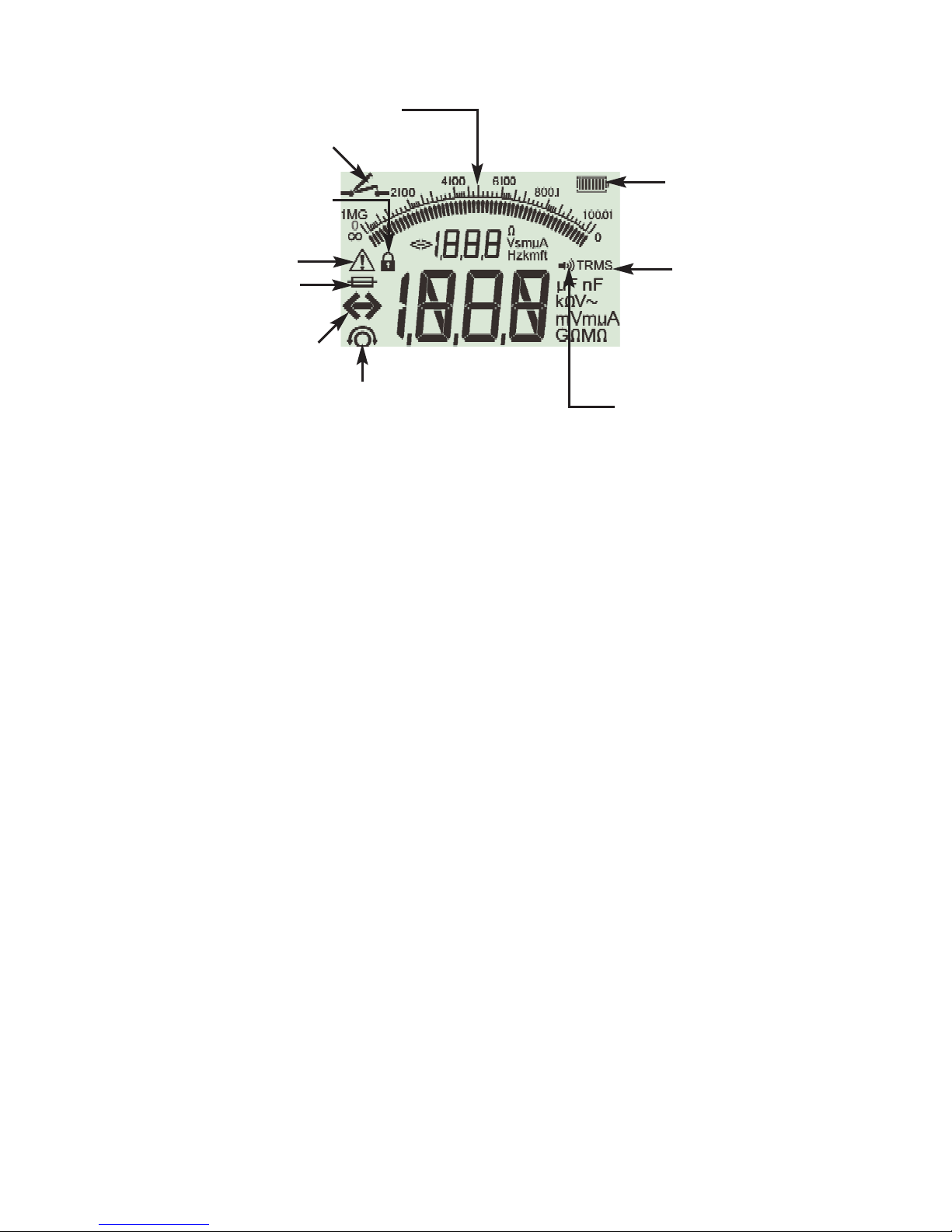
LCD Display
Figure 3 LCD display
In continuity mode, if a voltage greater than 25 V exists, testing will
be automatically inhibited and voltage measurement will be
displayed.
SP5 Switched probe
The SP5 switch probe allows the user to start a test by pressing the
[TEST] button on the probe, instead of on the instrument. This
allows for complete hands-free testing and increases user safety.
AC/DC voltage and frequency measurements
Note: Measured voltage must not exceed 600 V phase to earth or
Phase to Phase.
Note on TRMS measurement:
IN TRMS mode the MIT415 will measure both AC and DC
components of the supply voltage (AC+DC). In DC mode only the
DC component is measured.
1. Rotate selector switch to the ‘V’ position.
2. Connect test leads to the circuit under test.
3. Press the [TRMS] button to select DC or return to TRMS.
4. The measured voltage will be displayed on the main digital scale
in units of V or mV, as appropriate In TRMS mode, the measured
frequency (Hz) will be simultaneously displayed.
Insulation resistance testing - general
Safety note:
Insulation resistance testing is performed at high DC voltages and is
Auxiliary digital display
Continuity indicator
Lock indicator
Warning-refer to
user guide
Fuse blown
indicator
Out of range
indicator
Lead null indicator
Audible alarm
indicator
Battery
condition
indicator
TRMS
indicator
Page 6

hazardous if touched. Always observe the safety precautions when
performing an insulation resistance test, and ensure all necessary
health and safety precautions are observed.
Automatic Discharge: Capacitive circuits are automatically
discharged when the test button is released following an insulation
test.
The circuit under test must be completely de-energised and
securely isolated before test connections are made.
Standard insulation resistance testing
1. Connect the test probes to the isolated circuit under test.
2. Turn the instrument ‘ON‘ by rotating the selector switch to the
desired test voltage.
3. Press and hold the [TEST] button to start the test.
4. The insulation resistance value, in both analogue and digital form
is displayed together with the actual test voltage displayed on the
secondary display.
5. The insulation test can be locked on, by pressing the lock button
[ ] whilst holding down the [TEST] button. To disable lock
press the [TEST] button or lock [ ] button.
6. By pressing the [uA/V/s] button, the leakage current can be
displayed.
7. Release the [TEST] button before removing the test leads (to
enable the instrument to discharge the circuit under test). If the
display shows VOLTS, wait until it reaches zero.
8. On completion of testing, switch to the ‘
OFF’ position.
Insulation resistance testing – timed modes ‘t’, PI and
DAR
Three types of timed test are possible:
(a) Standard count down timer (t)
Timed tests are performed over a timed period defined by
parameter ‘t’ (also refer to Set-up procedures 13).
(b) Polarization Index (PI)
PI is the ratio between the insulation resistance values recorded at 1
minute (assigned t1) and at 10 minutes interval (assigned t2). i.e.
after 1 minute and 10 minutes.
PI = 10 minute value/1 minute value
(c) Dielectric Absorption Ratio (DAR)
Page 7

DAR is the ratio between the insulation resistance values at
30seconds (assigned t1) and at 60 second interval (assigned t2). i.e.
after 30seconds and 60seconds.
DAR = 60 second value/30 second value
During all insulation tests the symbol
G will flash indicating that a
test voltage is present.
(a) Insulation resistance testing-timed procedure.
1. Connect the test probes to the isolated circuit under test.
2. Turn the instrument ‘ON‘ by rotating the selector switch to the
required test voltage position.
3. Select the timed test (t) by pressing ‘PI/DAR/t’ function button
repetitively until the desired function is displayed.
4. Once selected, press and hold the [TEST] button to start the test.
5. To abort the test early, press TEST or LOCK [ ] buttons.
6. At the end of the tests, the voltage will be discharged.
(b) Insulation resistance testing – PI and DAR
The PI test will run for a period of 10minutes. After one minute a
test result is stored (t1). After 10 minutes a second test result is
stored (t2). The resultant ratio is then displayed on the screen.
The same procedure applies for the DAR timed tests, however the
test duration is 60 seconds, with the first result (t1) taken at 30
seconds and the second at 60 seconds (t2).
Results can be recalled to screen using the uA/v/s [
t] keys.
Note: DO NOT press PI/DAR/t [s] as it will change the test mode
and erase the current results.
Continuity testing [Ω
] and buzzer [ ]
1. Turn the instrument ‘ON’ by rotating the selector switch to
the desired Ω position.
2. If required the test lead resistance can be set to Zero (null) by
shorting the test leads together and pressing TEST. The null
[
z
] symbol will show when this has been achieved and the
display will read 0.00 Ω.
3. Press the [ ] button to enable/disable the audible buzzer
function. When enabled, the sounder symbol will be shown on
the screen display. The pass threshold is set to 2 Ω by default,
but is adjustable, as defined in Setup.
Note that the buzzer defaults to OFF on power-up.
4. Connect the test leads to the isolated conductor(s) under test.
Page 8

5. Observe the test result, displayed automatically. The auxiliary
display indicates the actual test current (e.g. 205 mA. The
maximum is defined in setup menu.
Note: The test current displayed is the actual test current used
during the test, which will depend on the resistance of the circuit
under test.
Resistance measurements (kΩ Range)
1. Turn the instrument ‘ON’ by rotating the selector switch to the
desired [kΩ] position.
2. Connect the test leads to the isolated conductors under test.
3. Observe the test result, displayed automatically.
Setup options
The setup position permits the user to adjust various threshold
values and default settings. When SETUP is selected, the instrument
firmware revision is displayed, followed by the buzzer alarm
threshold.
Displayed Meaning Default Setting
symbol setting options
BUZ Set top threshold for
continuity buzzer in ohms. 2 Ω 1, 2, 5, 10, 20
Buzzer sounds if result is
less than set value. Ω
Loc Lock button ON/OFF ON ON / OFF
ISC Setup maximum continuity
short-circuit current . 200 mA 20 mA, 200 mA
(default 200 mA)
Setup procedure
1. Turn the instrument ‘ON’ by rotating the selector switch to the
Setup position. The firmware version is displayed prior to the first
setting BUZ.
2. Press the TEST button repeatedly to select the desired parameter,
BUZ, Loc, ISC etc.
3. When the function to be changed is displayed,
press and hold
the TEST button to change the value. Each subsequent press
increments the limit. Holding down the TEST button will
automatically increment.
4. Changing a value will start the lock [ ] symbol flashing. This
Page 9

indicates a value has been changed but not saved.
5. Save new limit by pressing the Lock [ ] button. Saved changed
are effected when the Screen Lock symbol stops flashing and
disappears.
Battery and fuse replacement
Battery condition and replacement
The battery condition indicator is displayed at all times that the
instrument is switched on, as below: 100%, 75% and 50%.
Replacement batteries type is: 5 x LR6 (AA), 1.5 V alkaline, or 5 x
1.2V NiMH.
Note: NiMH or NiCAD rechargeable batteries show a lower charge
than alkaline batteries, and may not give much warning before
becoming exhausted.
Procedure to replace batteries
When the low battery symbol appears, the cells are nearly
exhausted and should be replaced as soon as possible. To install or
replace the cells, disconnect the test leads, switch the
instrument
OFF and loosen the screws holding the battery
compartment cover in place. Remove the cover and lift out the
cells. Ensure that the replacement cells are fitted with the correct
polarity in accordance with the label in the battery compartment.
Replace and re-secure the battery compartment cover. Remove the
cells if the instrument is not going to be used for an extended
period of time.
Blown fuse indicator
To check the instrument fuse, switch to an insuation range and
press the TEST button. If the fuse is ruptured, the flashing symbol is
displayed.
Note: The voltmeter will continue to operate for voltages greater
than 100 V at 50 Hz. To replace the fuse, disconnect the test leads,
switch the instrument OFF and loosen the screws holding the
battery compartment cover in place. Remove the cover and replace
the fuse of the correct type and rating. Replace and re-secure the
battery compartment cover.
Follow the same procedure as for battery replacement
A replacement fuse must be of the correct type and rating:
i.e. 500 mA (FF) H.B.C.50 kA min 1000 V (32mm x 6mm)
Preventive maintenance
When necessary, the instrument can be cleaned with a damp cloth.
Do not use alcohol based cleaners.
Page 10

Specification
All quoted accuracies are at +20 °C.
Insulation
Nominal test voltages: 10 V, 25 V, 50 V, 100 V, 250 V, 500 V
Range full scale accuracy
All ranges ±2% ±2 digits up to 100 MΩ.
Then:
500 volts. ±3% ±2 digits ±0.4% per GΩ
250 volts. ±3% ±2 digits ±0.8% per GΩ
100 volts. ±3% ±2 digits ±2.0% per GΩ
50 volts. ±3% ±2 digits ±4.0% per GΩ
25 volts. ±3% ±2 digits ±8% per GΩ
10 volts. ±3% ±2 digits ±20% per GΩ
Analogue range: 1 GΩ full scale
Short circuit current: 2 mA +0% -50%
Terminal voltage: -0% +20% ±1 V (Ii <1 mA)
Test current on load:
1 mA at min. pass value of insulation specified in BS7671,
HD384 and IEC364, EN61152-2, 2 mA max.
EN61557 operating range: 0,10 MΩ to 1,00 GΩ
Leakage current range: 10 µA to 2000 µA
Leakage current: 10% ±3 digits
Voltage display: 3% ±3 digits ±0.5% of rated
voltage
Dielectric absorption Ratio (DAR): 60sec / 30sec ratio
Notes:
(1) All ranges measure from 0,00 MΩ upwards.
(2) Above specifications only apply when high quality
silicone leads are being used.
Continuity
EN61557 operating range: 0,01 Ω
to 99,9 Ω
(0 to 100 Ω
on
analogue scale)
Accuracy: ± 2% ± 2 digits (0 to 100 Ω)
Open circuit voltage: 5 V ±1 V
Test current: 205 mA (±5 mA) (0.01 Ω to 9.99 Ω)
20 mA
(±1 mA) (10.0 Ω to 99.9 Ω)
Lead resistance zeroing: Up to 9,99 Ω
Page 11

Buzzer:
Variable limit 1 Ω, 2 Ω, 5 Ω, 10 Ω, 20 Ω
Resistance
EN61557 operating range:
0,01 kΩ to 1000 kΩ (0 to 1 MΩ on analogue scale)
Accuracy: ±3% up to 50 kΩ then ±5% ±2 digits
Open circuit voltage: 5 V ±1 V
Short circuit current: 1.5 mA ±0.2 mA
Voltage range
0 to 600 V d.c. ± 2% ± 2 digits
10 mV to 600 V TRMS sinusoidal (40 – 400 Hz) ±2% ±2 digits
0 to 1000 V on analogue scale
Unspecified input level 0 – 10 mV (40 – 400 Hz)
For non sinusoidal waveforms additional specifications apply:
±3% ±2 digits 101 mV – 600 V TRMS and
±8% ±2 digits 10 mV – 100 mV TRMS
Default Voltmeter
Operates at >25 volts a.c. or d.c., on any range except OFF
Frequency: 15-400Hz (15Hz - 99,9Hz) ±0.5% ±1 digit
(100Hz to 400Hz)
Power supply
5 x 1,5V cells type IEC LR6 (AA, MN1500, HP7, AM3 R6HP) Alkaline
NiMH rechargeable cells may be used.
Battery life
2200 insulation tests with duty cycle of 5 sec on 55 sec off
Dimensions 220 x 92 x 50 mm (8.66in x 3.63in x 1.97in)
Weight 590gms, 775gms with boot (20.73oz
(27.22oz))
Fuse
Use only a 500 mA (FF) 1000 V 32 x 6 mm ceramic fuse of high
breaking capacity HBC 50 kA minimum. Glass fuses MUST NOT be
fitted.
Safety Protection
The instruments meet EN 61010-1 (1995) to 600 V phase to earth,
Category IV.
Refer to safety warnings (see section 2).
E.M.C.
In accordance with IEC 61326 including amendment No.1
Page 12

Temperature effects
Temperature coefficient <0,1% per °C up to 1 GΩ
<0,1% per °C per GΩ above 1 GΩ
Environmental
Operating range: -20ºC to +55 °C
Operating humidity: 95% RH at 0ºC to +35ºC, 70% RH
+35ºC to +55ºC
Storage temperature range: -30ºC to +80 °C
Calibration Temperature: +20 °C
Maximum altitude: 2000 m
Dust and water protection: IP54
Accessories
Includes accessories
2 wire test lead set and crocodile clips 6220-813
SP5 Remote switch probe 6220-812
Calibration certificate
Rubber boot 6231-802
Instrument case 5410-420
User guide 2000-171
Optional accessories and replacements
Fused 2 wire test lead set and crocodile clips 6220-789
Page 13

REPAIR AND WARRANTY
The instrument circuit contains static sensitive devices, and care must be taken
in handling the printed circuit board. If the protection of an instrument has
been impaired it should not be used, and be sent for repair by suitably trained
a
nd qualified personnel. The protection is likely to be impaired if, for example,
the instrument shows visible damage, fails to perform the intended measurements, has been subjected to prolonged storage under unfavourable conditions,
or has been exposed to severe transport stresses.
New Instruments are Guaranteed for 3 Years from the
Date of Purchase by the User
Note: Any unauthorized prior repair or adjustment will automatically
invalidate the Warranty.
Instrument Repair and Spare Parts
For service requirements for Megger®Instruments contact :-
Megger Limited or Megger
Archcliffe Road Valley Forge Corporate Center
Dover 2621 Van Buren Avenue
Kent, CT17 9EN Norristown, PA 19403
England U.S.A.
Tel: +44 (0) 1304 502243 Tel: +1 (610) 676-8579
Fax: +44 (0) 1304 207342 Fax: +1 (610) 676-8625
or an approved repair company.
Returning an Instrument for Repair
If it is necessary to retun an instrument for repair, a Returns Authorisation
number must first be obtained by contacting one of the addresses shown.
You will be asked to provide key information, such as the instrument serial
number and fault reported when the number is issued. This will enable the
Service Department to prepare in advance for the receipt of your instrument,
and to provide the best possible service to you.
The Returns Authorisation number should be clearly marked on the outside
of the product packaging, and on any related correspondence. The
instrument should be sent, freight paid to the appropriate address. If
appropriate a copies of the original purchase invoice and of the packing note,
should be sent simultaneously by airmail to expedite clearance through
customs.
For instruments requiring repair outside the warranty period a repair
estimate will be submitted to the sender, if required, before work on the
instrument commences.
Approved Repair Companies
Megger operates fully traceable repair and calibration facilities complemented
by a network of approved repair and calibration companies, to offer excellent
in-service care for your Megger products. Megger’s streamlined Returns
Authorization system ensures your product is expected and enables you to
track its progress on-line.
Page 14

 Loading...