

Page 1
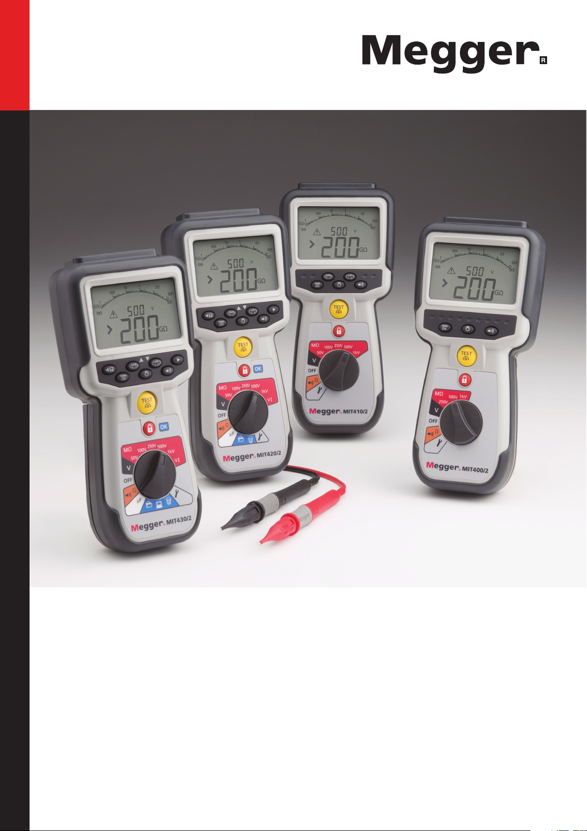
MIT400/2 Series
Insulation and continuity testers
User guide
Page 2

User guide contents
1. Introduction 3
2. G Safety Warnings 4
3. Symbols used on the instrument 5
4. General description 6
Unpacking the carton 6
Carton contents (all instruments) 6
5. Preparations for use (all instruments) 7
Batteries 7
Preliminary test lead check
6. General operating intsructions 8
General functions 8
LCD Display 9
Backlight operation 10
7. Test lead connections 11
Standard test leads 11
SP5 Switched probe (not MIT400/2, MIT480/2
and MIT40X) 11
8. AC/DC voltage and frequency
measurements 11
17. Battery and fuse replacement 32
Battery condition and replacement 32
Blown fuse indicator 33
18. Preventive maintenance 33
19. Specification 34
20. Basic and service errors 36
Basic error 36
Service error: 36
21. Accessories 37
22. Repair and Warranty 39
9. Insulation resistance testing - general 13
Standard insulation resistance testing 13
Insulation resistance testing –
timed modes ‘t’, PI and DAR 14
10. MIT40X testing 17
11. Continuity testing [Ω] and buzzer [
12. Resistance measurements (kΩ Range) 19
13. Capacitance measurements 20
Capacitance measurement procedure 20
Distance measurement by capacitance 20
14. Setup options 20
15. Saving, recalling and downloading
test results. 23
Saving test results 23
Test results recall 23
PI and DAR recall. 24
16. Deleting test results 26
Procedure for deleting a single test result
(refer to Figure 16) 26
Procedure for deleting all test results
(refer to Figure 19) 27
Preparing your MIT430/2 or MIT485/2 for
“Bluetooth
Preparing your MIT430/2 or MIT485/2
to your PC 29
Standard download operation 32
®
” Communications 29
] 18
www.megger.comMIT400/2
2
Page 3

1. Introduction
Thank you for purchasing the Megger insulation test instrument.
For your own safety and to get the maximum benefit from your instrument, please ensure that you read and understand the following
safety warnings and instructions before attempting to use the instruments.
This user guide describes the operation and functions of the MIT400/2 series of insulation and continuity test instruments.
These instruments are designed and manufactured by:
Megger Ltd
Archcliffe Road
Dover Kent CT17 9EN
England
Megger Limited reserves the right to change the specification of these instruments at any time without prior notice.
www.megger.comMIT400/2
3
Page 4
2. Safety Warnings
2.1 Safety Warnings
Safety warnings and precautions must be read and understood before the instrument is used. They must be observed during use.
National Health and Safety Legislation requires users of this equipment and their employers, to carry out valid risk
assessments of all electrical work so as to identify potential sources of electrical danger and risk of electrical injury such
as inadvertent short circuits. Where the assessments show that the risk is significant then the use of fused test leads
may be appropriate.
The voltage indicator and automatic discharge features must be regarded as additional safety features and not a
substitute for normal safe working practice which MUST be followed.
The circuit under test must be switched off, de-energized, securely isolated and proved dead before test connections
are made when carrying out insulation and continuity tests.
Test voltages greater than 1000 V dc must not be used on capacitive circuits. Capacitive charges can be lethal.
Circuit connections and exposed-conductive-parts and other metalwork of an installation or equipment under test must
not be touched during testing.
The Voltmeter function will operate only if the instrument is switched on and working correctly.
After an insulation test, the instrument must be left connected until the circuit has been discharged to a safe voltage.
Do not handle test leads above the 1000 V range. (For use in dry conditions only).
The instrument should not be used if any part of it is damaged.
All test leads, probes and crocodile clips must be in good order, clean and with no broken or cracked insulation. Verify
the integrity of the test leads before making measurements. Only “Megger” approved test leads must be used with this
product.
Ensure that hands remain behind finger guards of probes/clips.
National Safety Authorities may recommend the use of fused test leads when measuring voltage on high-energy
systems. Fused Leads must be tested independently before use to ensure fuse integrity.
Replacement fuses must be of the correct type and rating. Failure to fit the correctly rated fuse may result in a safety
hazard and may cause damage to the instrument in the event of an overload.
All covers must be in place whilst conducting tests.
If this equipment is used in a manner not specified by the manufacturer, the protection provided by the equipment may
be impaired.
The instrument must be used only by suitably trained and competent persons.
Safety symbols marked on the instrument
G refer to user instructions
F risk of electric shock
CATIV 600 V
terminals, and between terminal
and earth
protected against water splashes
g
> 600 V
600 V ac rms maximum between
IP54 Enclosure is dust proof and
f Fuse FF 500mA 1000V 30kA
t Equipment protected throughout
by Double Insulation.
EU directives.
current “C tick” requirements.
waste stream.
Equipment complies with current
N13117 Equipment complies with
Do not dispose of in the normal
www.megger.comMIT400/2
4
Page 5

Installation Category Definitions:
CAT IV - Measurement category IV: Equipment connected between the origin of the low voltage mains supply and the distribution
panel.
CAT III - Measurement category III: Equipment connected between the distribution panel and the electrical outlets.
CAT II - Measurement category II: Equipment connected between the electrical outlets and the user’s equipment.
Measurement equipment may be safely connected to circuits at the marked rating or lower.
2.2 WEEE Directive
The crossed out wheeled bin symbol placed on Megger products is a reminder not to dispose of the product at the end
of its life with general waste.
Megger is registered in the UK as a Producer of Electrical and Electronic Equipment. The Registration No is WEE/
HE0146QT.
For further information about disposal of the product consult your local Megger company or distributor or visit your local
Megger website.
2.3 Battery disposal
The crossed out wheeled bin symbol placed on the batteries is a reminder not to dispose of them with general waste at the end of
their life.
This product contains the following batteries - AA alkaline batteries.
They are located under the battery cover at the rear of the instrument.
They can be safely removed by following the instructions in the battery replacement section of this guide.
Dispose of batteries according to local authority regulations.
Megger is registered in the UK as a producer of batteries.
The Registration number is BPRN00142.
For Further information see www.megger.com
www.megger.comMIT400/2
5
Page 6

3. General Description
3.1 Case contents
There are important documents that you should read and keep for future reference.
3.2 Case contents (all instruments)
1 x MIT400/2 series instrument
1 x Hard carry case
1 x Red/black test lead set with clips
3 x Red/Blue/Black 2.5 kV test lead set (MIT2500 only)
6 x AA (LR6) batteries fitted
1 x Warranty card
1 x Calibration certificate
1 x Owners CD manual
1 x Quick start guide
1 x SP5 remote switched probe (Not MIT400/2)
1 x Download Manager software CD (MIT430/2 and MIT485/2 only)
IMPORTANT To extend your warranty to 3 years, please register your Instrument at www.megger.com within one month of purchase.
www.megger.comMIT400/2
6
Page 7

4. Preparations for use (all instruments)
4.1 Batteries
The Megger MIT400/2 series instruments are supplied with batteries fitted. When batteries become exhausted, refer to section 15 for
battery replacement.
Warning: Do not switch the instrument on or connect test leads with the battery cover removed.
4.2 Preliminary test lead check
Functional verification
1. Before each use of the instrument visually inspect the test leads, prods and crocodile clips to confirm that their condition is
good, with no damaged or broken insulation.
2. Check continuity of the test leads by firmly shorting the leads together and read the test lead resistance measurement directly
from the display, which should be less than 1.0 W.
Note: Supply voltage
This instrument is designed for use on isolated (dead) circuits. Prior to any testing and using an approved method, ensure the circuit to
be tested has been fully disconnected and is securely isolated from the supply prior to using the instrument.
www.megger.comMIT400/2
7
Page 8
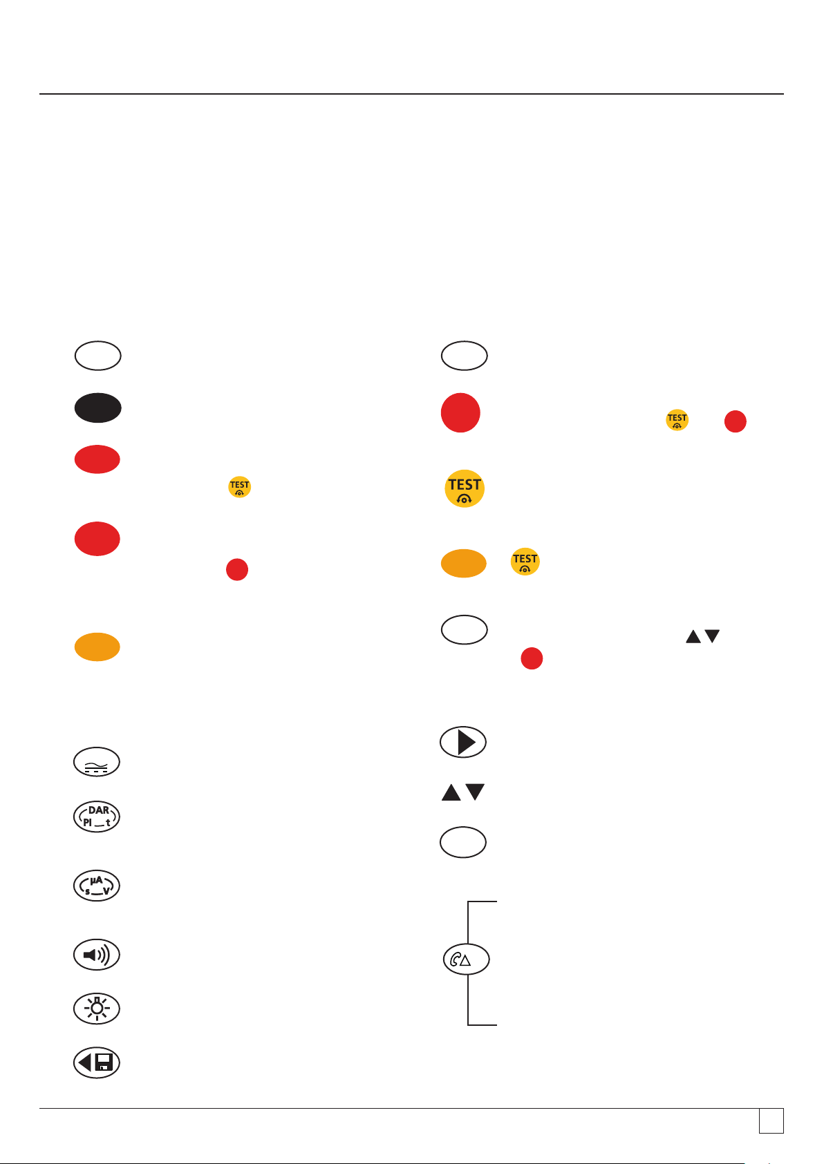
5. Instrument overview
W
5.1 General functions
5.1.1 Rotary knob position:
Test functions are selected by turning the rotary knob from the OFF position to the desired function. The display will show the initial
screen for that function.
Press a black keypad button to change the test mode from the standard measurement, or to select the Backlight and Buzzer ON/OFF.
The rotary knob should always be returned to the OFF position after use. Do not rely on the AUTO OFF function as this unnecessarily
wastes battery life.
OFF
Instrument OFF – no live circuit warning
V
Trms Voltage AC/DC
500 V
Insulation test range –
Press & hold
500 V
L
Insulation test range with gate*–
Press & hold
when selecting test function with rotary knob
(* where available)
W
Continuity measurement from 0.01W to
999 kW (automatic)
button
L
to enable enable range
5.1.2 Keypad button functions:
TRMS
Selects AC-Trms or DC mode
µF
Capacitance measurement ( automatic)
L
Insulation test lock - Press and L to
LOCK test ON
Start insulation test Press & HOLD to start
INSULATION test
W
+
when leads short circuit
Nulls test lead resistance to 0.00W
SET
UP
Enter SETUP configurator (use and
L
SETUP – Select setup function
to adjust settings)
SETUP – Change function value
Insulation testing - Selects DAR, PI, Timed test
(t) or standard measurement (INS)
Insulation testing – Press during test for;
leakage (uA), test voltage (V) or timer (t))
Buzzer ON/OFF – not warning functions
Backlight ON/OFF
SETUP – Change setup value / After test –
SAVE result
A+E+B
T+G+R
Swaps measurement connection between
A-B, A-E & B-E (T-R, T-G & R-G)
Continuity testing – Press after “Continuity
measurement” to make “difference
measurement”
Insulation testing – Measures REN value
during insulation test
Capacitance testing – Measures REN value
during capacitance test
www.megger.comMIT400/2
8
Page 9

5.2 Display contents
Storage and
downloading
symbols
-1510
G
W
M
k
W
9
-10
8
2100
0
7
+10
8
G
F
Warning and
Advisory symbols
Symbol Description Symbol Description
GW, MW, kW W, V , mV ,
A, mA, Hz, nF, uF
A E B
T G R
Units of measurement Measurement FAIL / PASS
Primary digital readout 3 Terminal selection status
61004100
kVs
M
H
A E B
T G R
6
+20
k V
zkAm
8100.1
W
µ
G mA
Mk
5
+30
k
ft
z
n
FdB
µ
mV
W
W WD
f
4
100.01
+35
0
W
µ
dB
Analogue arc and
pointer
Secondary digital
display
Main digital
display
LU
F
G
z
DW
Secondary digital readout REN measurement function enabled
Analogue readout with needle Transfer data to PC
Buzzer is enabled Save test measurement to memory
Lock enabled / disabled Test result recall to screen
Hazard voltage warning Delete test results
Warning - Read user manual Bluetooth® enabled
Lead Null is enabled Battery condition
Difference between two ohms
measurements
f
Fuse fail warning
www.megger.comMIT400/2
9
Page 10
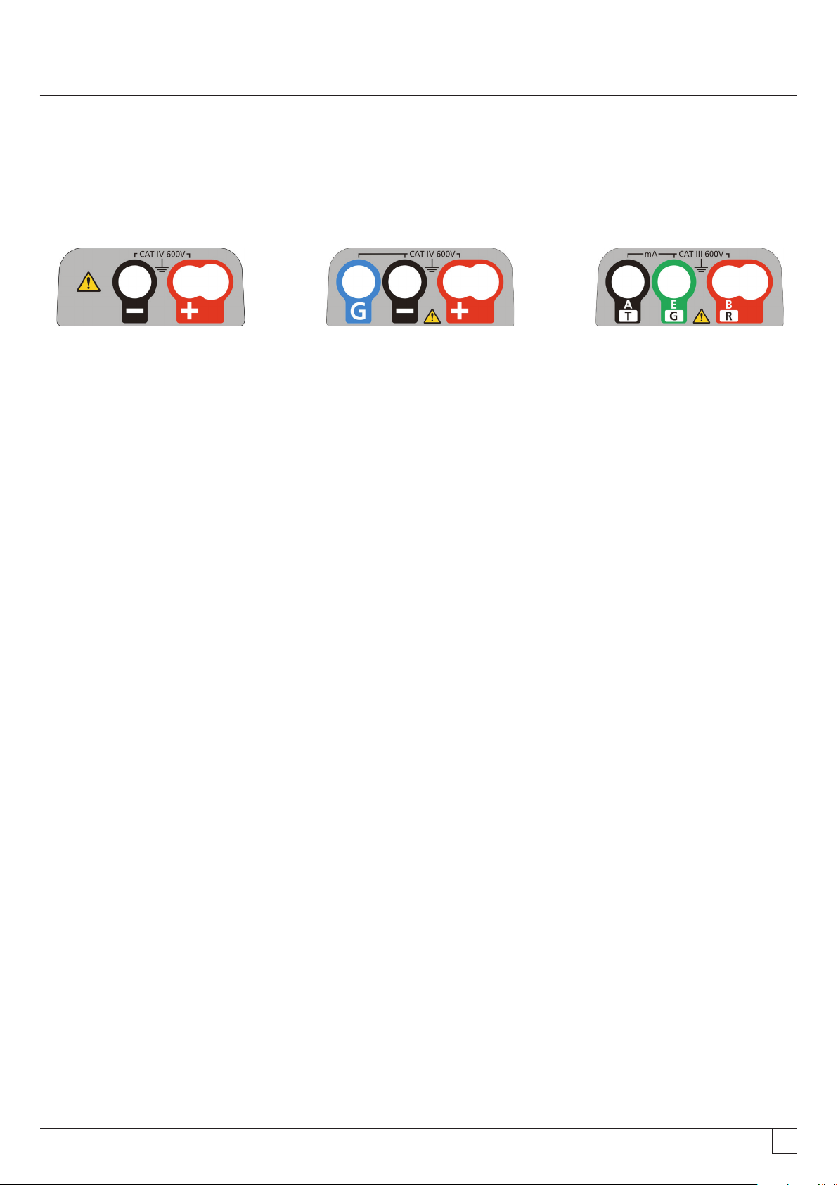
5.3 Terminal overview
2 terminal connection 2 terminal connection 3 terminal connection
+ Guard
www.megger.comMIT400/2
10
Page 11

6. General operating instructions
Safety note:
If greater than 25 V appears on the circuit under test the instrument will default to a voltage measurement and display
the supply voltage.
On supply voltages over 50 V the instrument will be prevented from performing an insulation test, protecting your instrument from
damage.
Note: This limit is increased on MIT481/2 and MIT485/2 to 75 V, but a warning buzzer will indicate voltages above
50 V.
Use extreme care when using or measuring voltages above 30 V, particularly in high energy systems.
Fused test leads are available as an optional accessory for local situations where increased protection is required.
Hazardous voltages can exist on the insulation test range all the time the [TEST]
button is locked down.
www.megger.comMIT400/2
11
Page 12
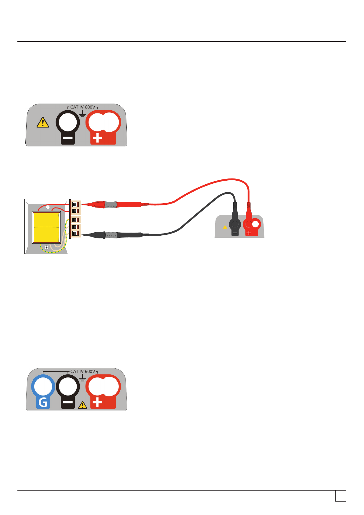
7. Input terminals
Test leads connections are as indicated in below, which shows the test lead sockets at the top of the instrument, as well as the
switched probe socket and test lead.
7.1 2 terminal test lead connection
Terminal layout - 2 terminal instruments:
- Figure 1
2 terminal connection examples:
CAT III 600 V
g
G
- Figure 2
For two terminal instruments (Fig 1), the Red and Black test lead set should be connected to the appropriate sockets on the top of the
instrument marked + and –, respectively. (see figure 1 ).
The RED terminal accepts the standard RED test lead or the Switch Probe lead where supplied.
7.2 2 terminal + GUARD (MIT2500)
The MIT2500 is fitted with a GUARD terminal. The GUARD terminal is used to conduct leakage currents away from the measured
circuit to reduce errors.
The GUARD terminal is ONLY used for insulation testing. Refer to Section 9
Terminal layout - 2 Terminal instrument + GUARD:
- Figure 3
For instruments with connection (figure 3) above, the Red / Black test lead set should be connected to the appropriate sockets on the
top of the instrument marked + and –, respectively. (see figure 3 ).
www.megger.comMIT400/2
12
Page 13
2 terminal + Guard connection example:
CAT III 600 V
g
G
G
- Figure 4
The GUARD lead (G) - refer to section 9 Insulation testing. is optional. When used it should be connected to the GUARD conductor,
screen, steel wire armoured conductor, or "user added" conductive wire or wrapper, such as foil. This "GUARD" conducts the
unwanted surface or "leakage current" away from the measured conductors.
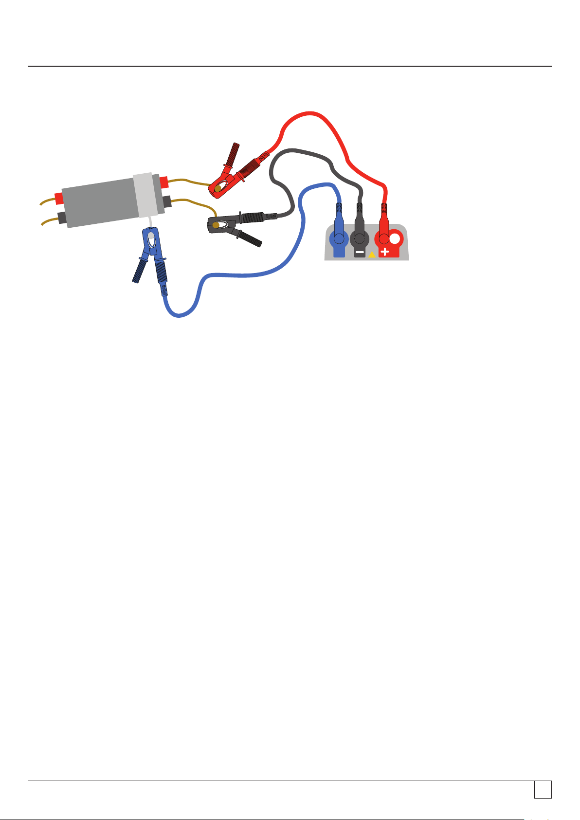
7.3 3 terminal test lead connection
Three terminal connection provides measurement between the 3 pairs of a telecommunication cable (A-B, A-E & B-E) or between
single or three phase conductors (L-N, L-E, N-E) and (L1-L2, L1-L3 & L2-L3).
Alternatively, only a single pair can be used (default Red and Black) for conventional 2 wire measurement.
7.3.1 How 3 terminal connection works
The 3 terminal connections allow measurements to be made across any 3 terminals:
A-B, A-E or B-E (T-R, T-G, R-G)
This reduces the number of connections necessary to a circuit, especially where live working has been authorised. Once all three
leads are connected, measurements between the three terminals can be made.
For example:
Electrical testing:
Where two conductors need to be measured to a screen or shield
Where Live, Neutral and Earth need measuring
Comparing continuity of conductors to a ground terminal for difference measurements
Testing centre tapped electrical installations.
Telecommunications:
Testing voltage, continuity and Insulation between A, B and E or Tip Ring and Ground, without having to disconnect
test leads.
www.megger.comMIT400/2
13
Page 14

Terminal layout - 3 Terminal instrument:
- Figure 5
3 Terminal connection example:
B / Ring / Live
CAT III 600 V
E / Ground / Earth
A / Tip / Neutral
A
T
g
E
B
G
R
G
- Figure 6
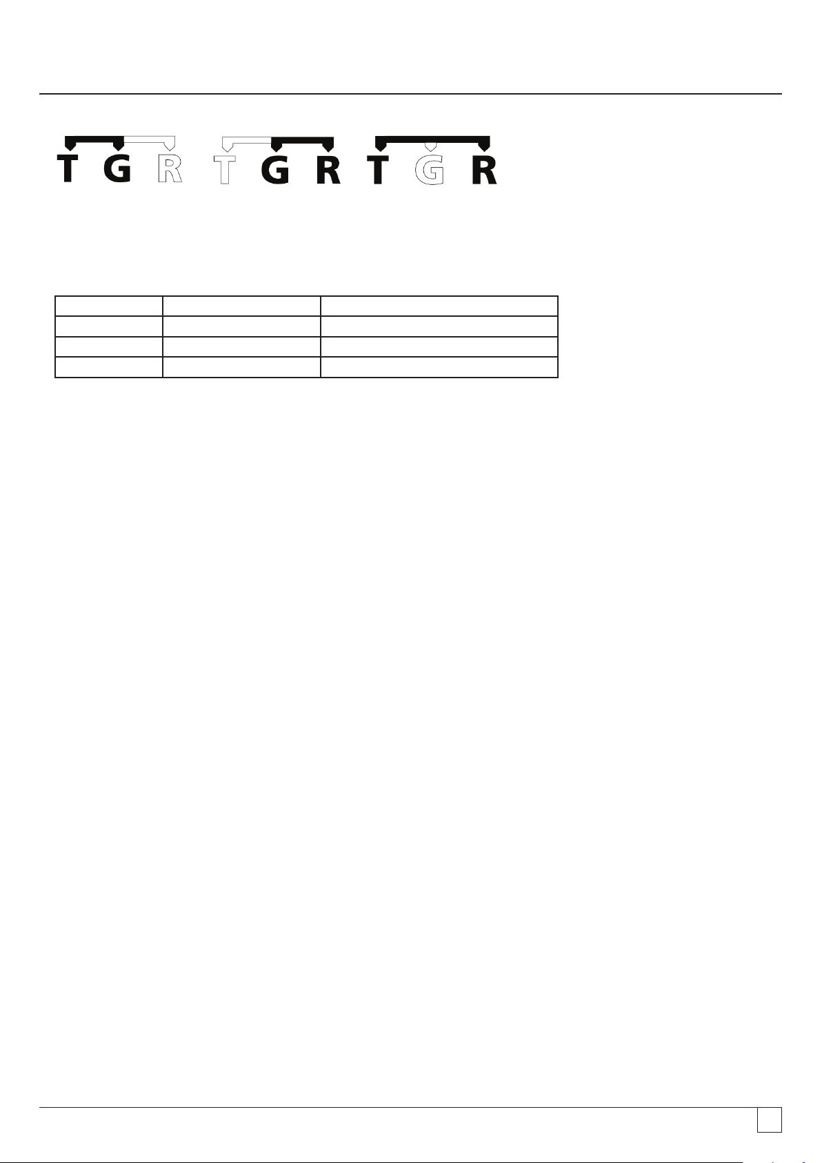
7.3.2 3 terminal operation:
By pressing the A-E-B button on the keypad the active measuring pair on the Instrument changes as per the indication on the display,
as below:
- Figure 7
With each press, the display will change from:
From
- Figure 8
to to and back to
Or, if 'T-G-R' is enabled in setup:
From
to to and back to
For example, in VOLTS mode, the voltages on the A-B pair, the A-E pair or the B-E pair can all be measured without having to
disconnect the test leads from the A, B and E conductors.
www.megger.comMIT400/2
14
Page 15

For electrical applications the test leads can be connected to Live (B), Neutral (A) and Earth (E) and the voltages measured and stored
without having to disconnect the test leads from the three conductors.
Test probes and crocodile clips are supplied for connection to the circuit under test.
Fused test leads are available as an optional accessory.
7.4 SP5 Switched probe (not MIT400/2, MIT405/2 )
The SP5 switch probe allows the user to start a test by pressing the test button on the probe, instead of on the instrument. This allows
for complete hands-free testing and increases user safety as below:
1. Connect the SP5 probe to the instrument using the special 3-pole +ve socket ( this replaces the RED test lead).
2. Select a suitable insulation resistance range.
3. Press and hold down the SP5 probe button. The instrument will start an insulation resistance test.
4. To end the test, release the probe test button.
www.megger.comMIT400/2
15
Page 16

8. Voltage and frequency measurements V
Note: Measured voltage must not exceed 1000 V phase to earth or Phase to Phase.
Exceeding this voltage could cause damage or electric shock hazard
Frequency measurement is not available on MIT400/2 and MIT405/2 model
Note on TRMS measurement: In TRMS mode the MIT will measure both AC and DC components of the supply voltage and display
the Trms value. In DC mode only the DC component is measured.
8.1 For 2 terminal instruments and MIT2500
8.1.1 AC Trms Voltage - Test procedure
1. Connect test leads to the RED and BLACK test sockets on the instrument.
V
2. Select the VOLTAGE measurement mode using the range knob [
3. Connect the test leads to the circuit to be measured.
4. The instrument will display the voltage across the test leads, as below:
]
2 00
0
6 004 00
8 00
100 0
z
H
V
- Figure 9
8.1.2 DC Voltage measurement
1. Repeat steps (1) to (4) above
2. Press the Trms AC/DC test button (below) to switch to DC measurement.
- Figure 10
The display will show a DC measurement as below:
2 00
0
6 004 00
8 00
100 0
V
- Figure 11
www.megger.comMIT400/2
16
Page 17

8.2 For 3 terminal instruments (MIT481/2, MIT485/2 only)
8.2.1 Using 2 test leads
1. Ensure instrument is in the A-B mode indicated in the display, as below:
- Figure 12
For details of changing the configuration see section 7.3 - 3 terminal connections.
2. Connect test leads to the RED/BLACK (B/A) test sockets only.
V
3. Select the VOLTAGE measurement mode on the range knob [
4. Connect the test leads to the circuit to be measured.
5. The instrument will display the voltage across the test leads as below.
] range).
2 00
0
6 004 00
8 00
100 0
z
H
V
A B
- Figure 13
Note: the display shows the A-B terminals are active.
6. If the display does not show the A-B option, press the A-E-B (T-G-R) button to change this mode, as below:
- Figure 14
7. With each press, the display will change from:
to to and back to
- Figure 15
Or, if 'T-G-R' is enabled in setup:
www.megger.comMIT400/2
17
Page 18
to to
- Figure 16
8.2.2 Using 3 test leads
All three connections can be connected to the circuit under test, for example:
Electrical testing Telecommunications USA Telecommunications EU
A = Neutral T = Tip A = A
B = Live R = Ring B = B
E = Earth E = Earth E = E
The measurement should default to Live - Neutral (A-B) when the instrument is switched on.
Pressing the A-E-B (T-G-R) button will cycle through the voltages on each part of the circuit, see section 7.2.
8.3 Result storage:
For MIT420/2, 430/2, 481/2, 485/2 and the MIT2500 the measured result may be stored (if required) by pressing the ‘STORE’
button for > 1sec. Refer to section 12 for further information.
WARNING - Where the A-E-B (T-G-R) symbol disappears, a voltage is present on a pair not currently selected, Press A-E-B
(T-G-R) to locate the live pair or pairs.
www.megger.comMIT400/2
18
Page 19

9. Insulation resistance testing
Safety notes:
Danger of electric shock: Insulation resistance testing is performed at high DC voltages and is hazardous if touched. Always observe
the safety precautions when performing an insulation resistance test, and ensure all necessary health and safety precautions are
observed.
On the MIT2500 only use the 2.5 kV test lead set on test ranges above 1 kV.
Never hold test leads when using test ranges above 1 kV.
Circuit Isolation: The circuit under test must be completely de-energized and securely isolated before test connections are
made.
Automatic Discharge: Capacitive circuits are automatically discharged when the test button is released following an insulation test.
This is a safety feature to prevent hazardous voltages remaining on test circuits after testing is completed.
Live circuit detection:
Insulation tests must only be conducted on dead, isolated circuits. However, occasionally a live circuit may be connected by accident or
isolated circuits have a voltage present through coupling to an adjacent circuit.
If a voltage below 30 V appears on the circuit under test the instrument will complete a measurement.
On circuit voltages over 30 V the instrument will sound a warning buzzer and display the circuit voltage on test ranges that are not
designed to measure voltage, such as the insulation test. The instrument will be prevented from performing an insulation test. See
section 13 - SETUP
Note: The test disable limit is increased on MIT481/2 and MIT485/2 to 75 V, but a warning buzzer will indicate voltages
above 30 V.
Use extreme care when using or measuring voltages above 30 V, particularly in high energy systems.
Fused test leads are available as an optional accessory for local situations where increased protection is required. See section 13 -
SETUP
Hazardous voltages can exist on the insulation test range all the time the [TEST] button is locked down.
9.1 Measurement for 2 terminal instruments and MIT2500
Note: For all insulation tests up to 1000 V, the RED test lead can be replaced by the SP5 switched test probe.
The SP5 switch probe button operates the test functions in exactly the same way as the TEST button on the instrument, but without
having to look away from the equipment being tested.
9.1.1 Insulation testing
1. Connect test leads to the RED / BLACK test sockets on the instrument.
MW
2. Select one of the test voltages on the insulation (MW) measurement mode using the range knob [
display the range voltage selected in the display as below:
100
G
W
110
8
0.1
0.01
V
0
G
W
100
8
110
0.1
0.01
0
]. The Instrument will
W
M
- Figure 17 MIT420/2 and MIT430/2 -Figure 17a MIT400/2 and MIT410/2
3. Connect the test leads to the circuit to be measured.
M
W
www.megger.comMIT400/2
19
Page 20

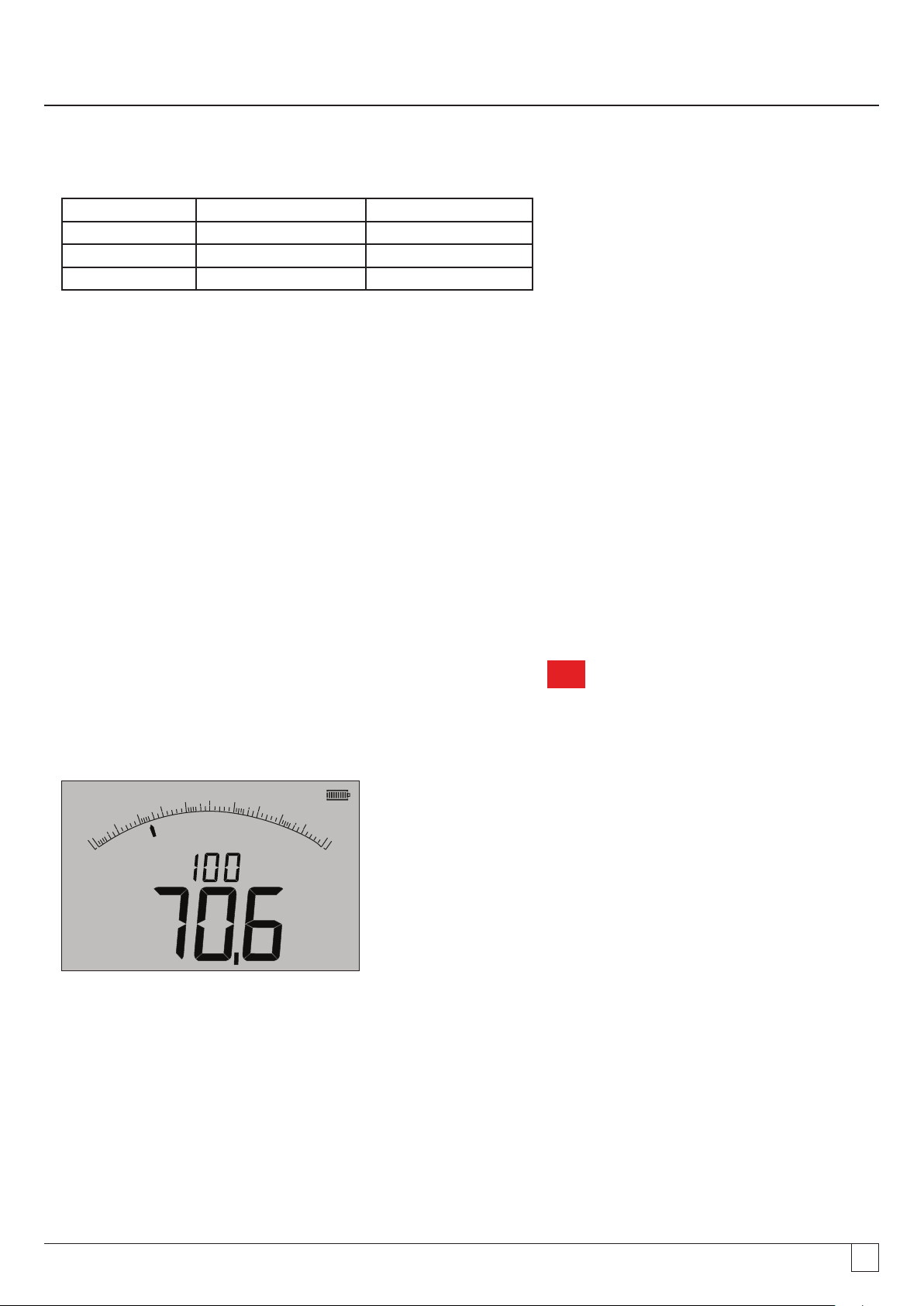
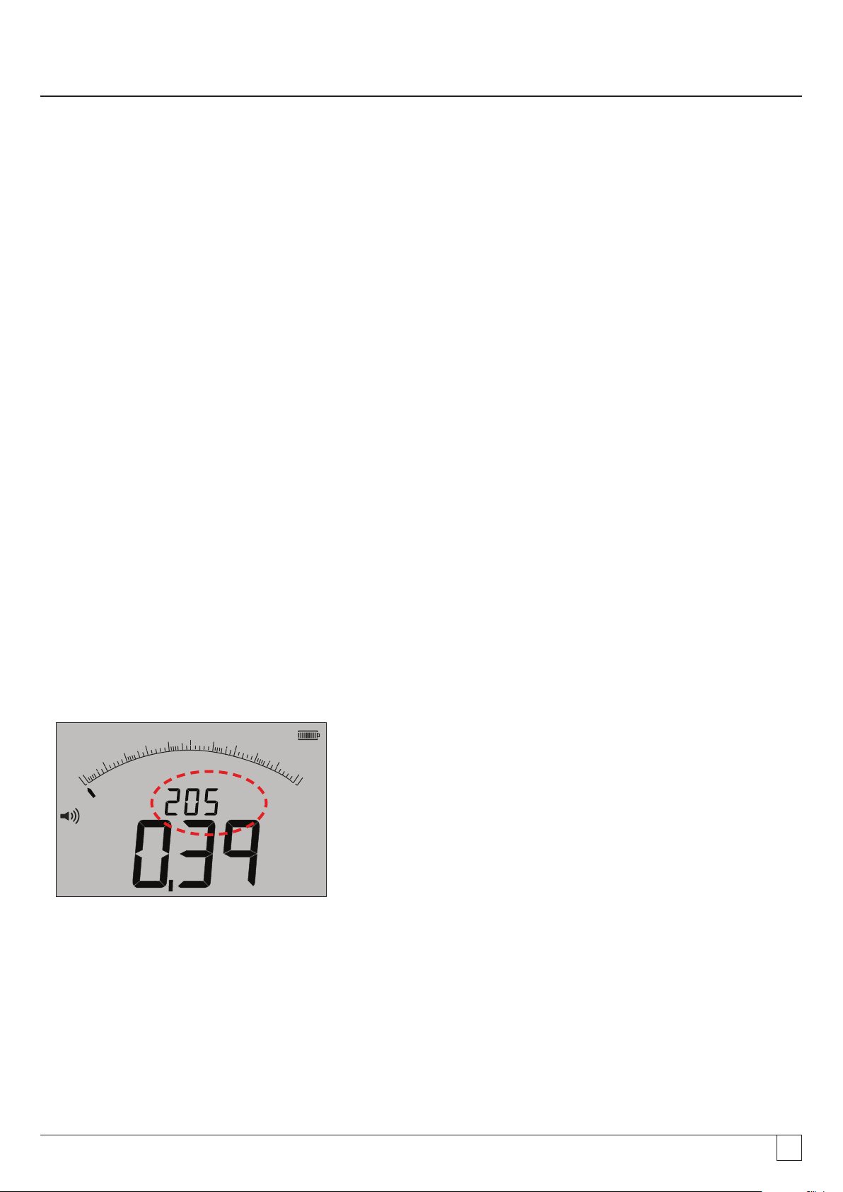
4. Press the TEST button. The display will show the measured insulation value in both the analogue arc and large digital readout.
The test voltage at which the measurement was made is displayed on the small digital readout), as highlighted below:
100
G
W
110
8
0.1
0.01
0
V
G
W
G
- Figure 18
5. Release the TEST button on completion of the test. The instrument will now discharge the circuit, ensuring it is left in a safe
condition at the end of the test.
WARNING: Locking on the insulation test, or disconnecting the leads before the test has completed can leave the circuit is a
dangerously charged condition, with risk of electric shock.
9.1.2 Buzzer PASS/FAIL threshold
The MIT will sound a buzzer If the measured value is greater than the threshold configured in SETUP. Refer to SETUP section 13.
9.1.3 Buzzer ON/OFF
The buzzer can be disabled by pressing the BUZZER button on the keypad as below:
- Figure 19
Note: Switching OFF the buzzer will disable the buzzer function but NOT the warning alarms.
9.1.4 Measurement PASS/FAIL
The display can show PASS or FAIL when the measurement is above or below the threshold in Setup when enabled. Refer to section
13 SETUP. This supersedes the test voltage display.
100
G
W
110
8
0.1
0.01
0
G
W
G
- Figure 20
www.megger.comMIT400/2
20
Page 21

Note: This function is Independent of the Buzzer ON/OFF mode.
9.1.5 Insulation test LOCK
To lock the insulation ON:
MW
1. Select one of the test voltages on the MW measurement mode using the range knob
2. Connect the test leads to the circuit to be measured.
3. Press and hold down the TEST button. Whilst the test is running, press the LOCK button. Release the LOCK and TEST buttons.
The LOCK symbol should be displayed and the test will continue to run.
DO NOT DISCONNECT THE TEST LEADS WHILST THE TEST IS LOCKED ON AS THE CIRCUIT CAN BE LEFT IN A CHARGED AND
HAZARDOUS CONDITION.
To unlock the insulation test, press the TEST button.
.
9.1.6 Leakage current
To display the insulation test value as a leakage current:
MW
1. Select one of the test voltages on the MW measurement mode using the range knob [
2. Connect the test leads to the circuit to be measured.
3. Press and hold down the TEST button. Whilst the test is running also press the uA/s/v button as shown below:
].
- Figure 21
The display will replace the insulation test voltage with the leakage current during the insulation test, as below:
100
G
W
110
8
G
Note: Smaller readout displays leakage current.
- Figure 22
4. Press the uA/s/v button again to return to test voltage display.
0.1
0.01
0
A
µ
W
G
www.megger.comMIT400/2
21
Page 22

9.2 Variable voltage insulation testing (MIT430/2, MIT485/2, MIT2500)
The MIT430/2, MIT485/2 and MIT2500 have a variable voltage mode of insulation testing. Indicated by the symbol
The voltage can be selected between the bottom and top test voltages on the instrument.
This value can be changed in 1V increments to 100V and 10V increments above 100V
The test voltage is configured in SETUP, see section 13.
All insulation test functions work for this test mode as they do for a standard test voltage.
Measurement range and accuracy is as per the lower standard test voltage, for example
Range and accuracy @ 76V = 50V test range accuracy
Range and accuracy @ 350V = 250V test range accuracy
The set voltage is retained when the instrument is switched off.
V
.
9.3 Polarisation Index (PI) and Dielectric Absorption Ratio (DAR)
These are fully automatic tests that require no user intervention after the test has started.
Three types of timed test are possible:
(a) Standard count down timer (t)
Timed tests are performed after a timed period defined by parameter ‘t’ (also refer to SETUP section 13)
(b) Polarization Index (PI)
PI is the ratio between the insulation resistance values recorded at 1 minute (assigned t1) and at 10 minutes interval
(assigned t2). i.e. after 1 minute and 10 minutes.
PI = 10 minute value / 1 minute value
(c) Dielectric Absorption Ratio (DAR)
DAR is the ratio between the insulation resistance values at 30 seconds (assigned t1) and at 60 second interval (assigned t2).
i.e. after 30seconds and 60seconds.
DAR = 60 second value/30 second value
During all insulation tests the symbol
G will flash indicating that a test voltage is present.
9.3.1 DAR,
1. Select one of the test voltages on the MW measurement mode using the range knob [
2. Connect the test leads to the circuit to be measured.
3. Press the DAR-PI-T button on the keypad as below:
- Figure 23
MW
].
www.megger.comMIT400/2
22
Page 23

The small digital readout should change from displaying the selected test range (in Volts) to PI, to DAR, T and INS, as below:
G
0
0.01
0.1
110
100
W
8
W
M
100
G
W
110
8
100
1
G
W
110
8
M
0.1
0.1
W
0
0
0.01
0.01
100
G
W
110
8
0.1
0.01
0
W
M
- Figure 24
4. Select the DAR function.
5. Press and release the TEST button to start the test. The display will show a count-down timer and the current insulation value,
as above:
100
G
W
110
8
0.1
s
0.01
0
M
W
G
W
- Figure 25
At the first measurement interval the MIT will display the measured value and log this in temporary memory.
100
G
W
110
8
M
0.1
0.01
s
0
G
W
M
Note: At 30 seconds the measurement is logged internally. This value is not stored in memory unless the "SAVE" button is pressed
AFTER the DAR measurement is complete. See section 9.3.3.
- Figure 26
www.megger.comMIT400/2
23
Page 24

At the end of the test period the MIT will make a second measurement and display the results as a ration of the 1st and 2nd measured
W
M
values, as below:
100
G
W
110
8
Note: Second measurement is logged at 0 seconds. Again, this is not stored in memory unless the "SAVE" button is pressed at the
completion of the test, see section 9.3.4
- Figure 27
0.1
0.01
0
9.3.2 Polarisation Index
The same method as in 9.3.1 above is used. Only the test times change.
9.3.3 Timed tests:
Timed tests run a countdown timer and make a measurement at the end of the timed period.
MW
1. Select one of the test voltages on the MW measurement mode using the range knob
.
2. Connect the test leads to the circuit to be measured.
Press the DAR-PI-T button on the keypad until the display show "t" on the small digital readout, as below:
100
1
G
W
110
8
- Figure 28
3. Press the TEST button. A count down from the limit configured In the SETUP menu will start. At the end of the count down,
the MIT will make a measurement and display the result as a resistance.
0.1
0.01
0
9.3.4 Storing Insulation test results
For MIT420/2, 430/2, 481/2, 485/2 and the MIT2500 At the end of the measurement, press the STORE button on the keypad. The
results will be stored in memory. For details of stored results refer to the STORAGE/DOWNLOAD section 12.
9.4 For 3 terminal instruments (MIT481/2, MIT485/2 only)
Insulation tests can be made using the three terminal, for example terminal connection, or just two terminals. As default, the
measurement is made across the RED/BLACK (B-A) pair, but can be changed, as below:
www.megger.comMIT400/2
24
Page 25

9.4.1 Using 2 test leads on a 3 terminal instrument
A measurement can be made across any of the three pairs, as long as the pair Is displayed In the screen.
1. Ensure instrument is in the A-B mode indicated in the display, as below:
- Figure 29
For details of changing the configuration see section 7.3 - 3 terminal connections.
2. Connect test leads to the RED/BLACK test sockets only.
MW
3. Select one of the INSULATION measurement voltages on the range knob
4. Connect the test leads to the circuit to be measured.
5. The instrument will display the voltage across the test leads as below.
6. If the display does not show the A-B option, press the A-E-B (T-G-R) button to change this mode.
.
2 00
0
A B
- Figure 30
7. With each press, the display will change from:
- Figure 31
Or, if 'T-G-R' is enabled in setup:
- Figure 31a
6 004 00
to to
to to
8 00
V
W
G
100 0
www.megger.comMIT400/2
25
Page 26
9.4.2 Using 3 test leads
All three connections can be connected to the circuit under test, for example:
Electrical testing Telecommunications USA Telecommunications EU
A (T) = Neutral T = Tip A = A
B (R) = Live R = Ring B = B
E (G) = Earth E = Earth E = E
The measurement should default to Live - Neutral (B-A) when the instrument is switched on.
Pressing the A-E-B (T-G-R) button will cycle through the voltages on each part of the circuit, see section 7.2.
9.5 ESD testing mode (MIT415)
The MIT400/2 can be configured in SETUP to display an analogue arc with 104, 105, 106 etc on the analogue arc rather than the kW,
MW, GW.
6
The mode also enables a PASS/FAIL limit bar, which stops at 10
A limit alarm can also be set in SETUP if required.
9.5.1 Testing in ESD mode
To enable the ESD mode, refer to SETUP section 13.
to indicate a PASS threshold without setting a limit alarm.
1. Connect test leads to the RED/BLACK test sockets only.
MW
2. Select one of the INSULATION measurement voltages on the range knob [
] range.
3. Connect the test leads to the appropriate test weights and place the test weights on the surface of the material to be
measured, as per the relevant test standard requirements.
4. Press and hold the test button. The instrument will display the resistance across the test leads as below:
8
10
9
10
W
7
6
1010
10
5
4
10
V
W
M
- Figure 32
Notes:
To LOCK the insulation test ON, see section 9.1.5.
9.5.2 Leakge current display
Whilst the test is running it is possible to display the leakage current rather than the test voltage in the smaller digital readout.
To display the LEAKAGE CURRENT during the test, see section 9.1.6
www.megger.comMIT400/2
26
Page 27
10. Continuity testing W
Continuity testing operates over the range 0.01 ohms to 999 kohms.
The MIT will auto-range across the full range from 0.01 ohm to 1 Mohm.
The analogue arc will auto range as below:
0 - 10 ohm
0 - 1 Mohm
Test current automatically adjusts for the range selected by the instrument. Test currents adjust as below:
0.01 to 3.99 ohms = 200 mA (or 20 mA depending on settings - see section 13 SETUP)
4.00 to 999 kohms = 20 mA to 2µA
The test operates at 4.5Vdc and is a single polarity test by default, as below, but can be set to a bi-directional test in setup, see also
section 13 below.
ie Red terminal = 4.5 Vdc, Black terminal = 0 Vdc
The continuity test is automatic. The test starts on detection of a circuit of <1 Mohm.
10.1 Measurement for 2 terminal instruments and MIT2500
10.1.1 Continuity testing W
1. Connect test leads to the RED/BLACK test sockets on the instrument.
2. Select the W measurement mode using the range knob.
3. Connect the test leads to the circuit to be measured. The instrument will check for a live circuit prior to making a
measurement.
4. On circuits of less than 1.0 Mohm, measurement starts automatically. The display will show the continuity value in both the
analogue arc and large digital readout. The test current at which the measurement was made is displayed on the small digital
readout, as highlighted below:
2 00
0
W
k
6 004 00
8 00
100 0
Am
z
W
- Figure 33
www.megger.comMIT400/2
27
Page 28

10.2 Single or bi-directional testing
The default setting is for a single direction continuity test. This can be changed to a bi-directional test in SETUP. see section 13.
First test: Red terminal = 4.5Vdc, Black terminal = 0Vdc
Second test: Red terminal = 0Vdc, Black terminal = 4.5Vdc
As with the single test, the Bi-directional test the measurement is automatic. The measurement displayed is the higher of the two
directional measurements.
Polarity of the primary result is shown in the display as an arrow:
-> = Forward polarity
<- = reverse polarity
Both the single and bi-polar tests are automatic, starting as soon as the test leads contact the circuit to be tested.
2 00
0
W
k
6 004 00
8 00
100 0
Am
z
W
- Figure 34
10.3 Test lead NULL
Enabling the lead NULL value
The test lead resistance can be removed from the displayed measurement. This "Null" is restricted to to 9.99 0hms
The "Null" value is retained when an instrument Is switched off.
It is recommended the "Null" value is checked or re-nulled periodically as the resistance of test leads and/or their connections can
change over time or after disconection and reconnection.
1. Whilst in continuity mode, short the test leads together.
2. When the value settles, press the TEST button. The MIT will subtract the value of the test leads for all future measurements,
until the NULL value has been removed.
The NULL symbol
Typical test lead values per pair:
These are only a guide and can change significantly between manufacturers.
z will be displayed when the NULL function is active.
Standard unfused 1.2m test leads = 0.05 ohm
10A fused 1.2 m test leads = 0.07 ohm
500mA Fused 1.2m test leads = 1.80 ohms
Removing the lead NULL value
1. With the test leads open circuit, press the TEST button. The null value should disappear and the display should show the test
lead resistance.
www.megger.comMIT400/2
28
Page 29
10.4 Buzzer PASS/FAIL threshold
The MIT will sound a buzzer If the measured value is less than the threshold configured in SETUP. Refer to SETUP section 13.
10.5 Buzzer ON/OFF
The buzzer can be disabled by pressing the BUZZER button on the keypad as below:
- Figure 35
Note: This will disable the buzzer sound but NOT the warning alarms
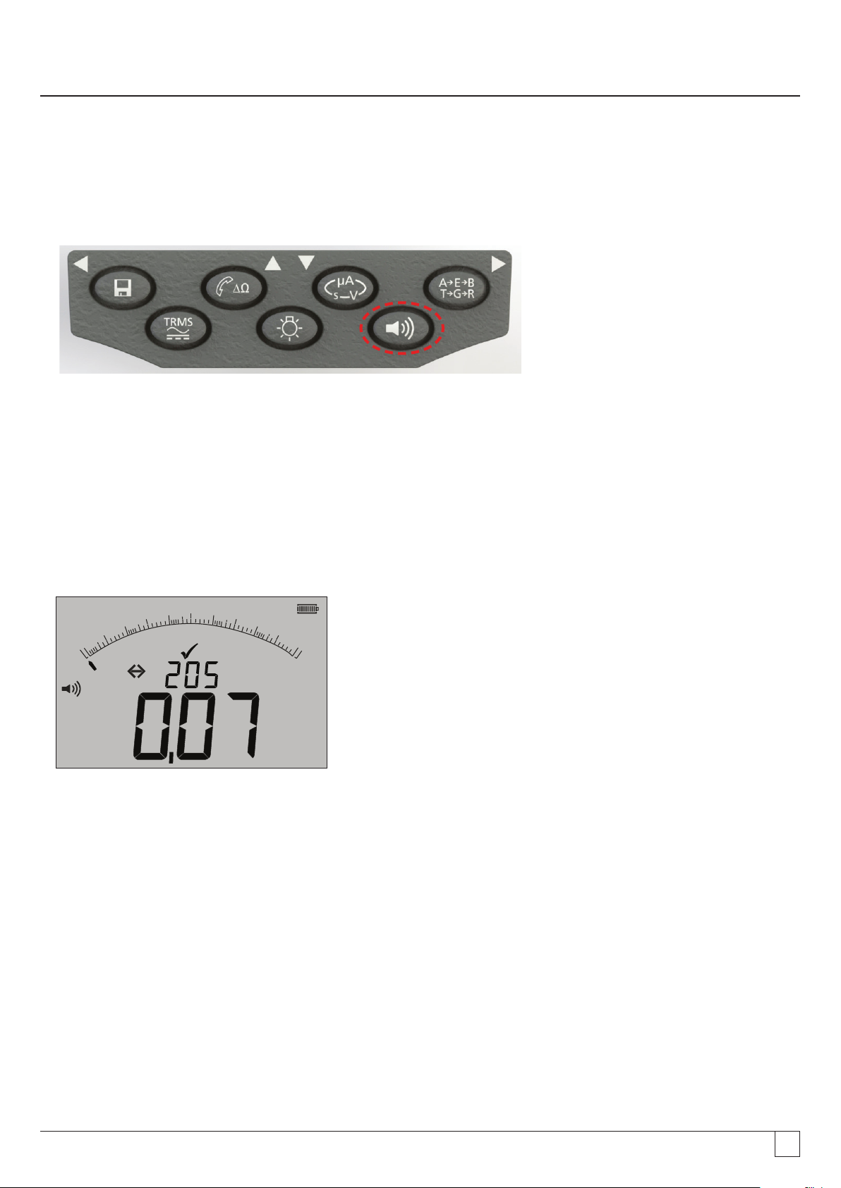
10.6 PASS / FAIL limit alarm
A Pass/Fail threshold can be configured in setup, such that the buzzer sounds when the value is below a selected value. This value is
stored in SETUP and retained until it is modified by the user or the instrument is reset to factory defaults.
The display will show a TICK or CROSS when the measured value is below or above the threshold set.
2 00
0
W
k
6 004 00
8 00
100 0
Am
z
W
- Figure 36
10.7 Test current - 20 mA / 200 mA
The continuity test current can be changed from 200 mA to 20 mA where extended battery life is the prority, refer to section 13 SETUP (ISc)
10.8 Measurement for 3 terminal instruments
See section 7.3
www.megger.comMIT400/2
29
Page 30
11. Capacitance measurements
(Except MIT400/2, 410/2)
The MIT400/2 can measure circuit or component capacitance.
The test is automatic and starts the test immediately on connection of a circuit. If capacitance is large the circuit can take time
to charge. During this charge time the display will show "- - -". On completion of the test the display will show the measured
capacitance, and under range symbol "<1.0 nf" or an over range symbol >10uF".
11.1 Capacitance measurement procedure (2 terminals)
1. Connect test leads to the RED/BLACK test sockets on the instrument.
2. Select the uF measurement mode using the range knob.
3. Connect the test leads to the circuit to be measured. The instrument will check for a live circuit prior to making a
measurement.
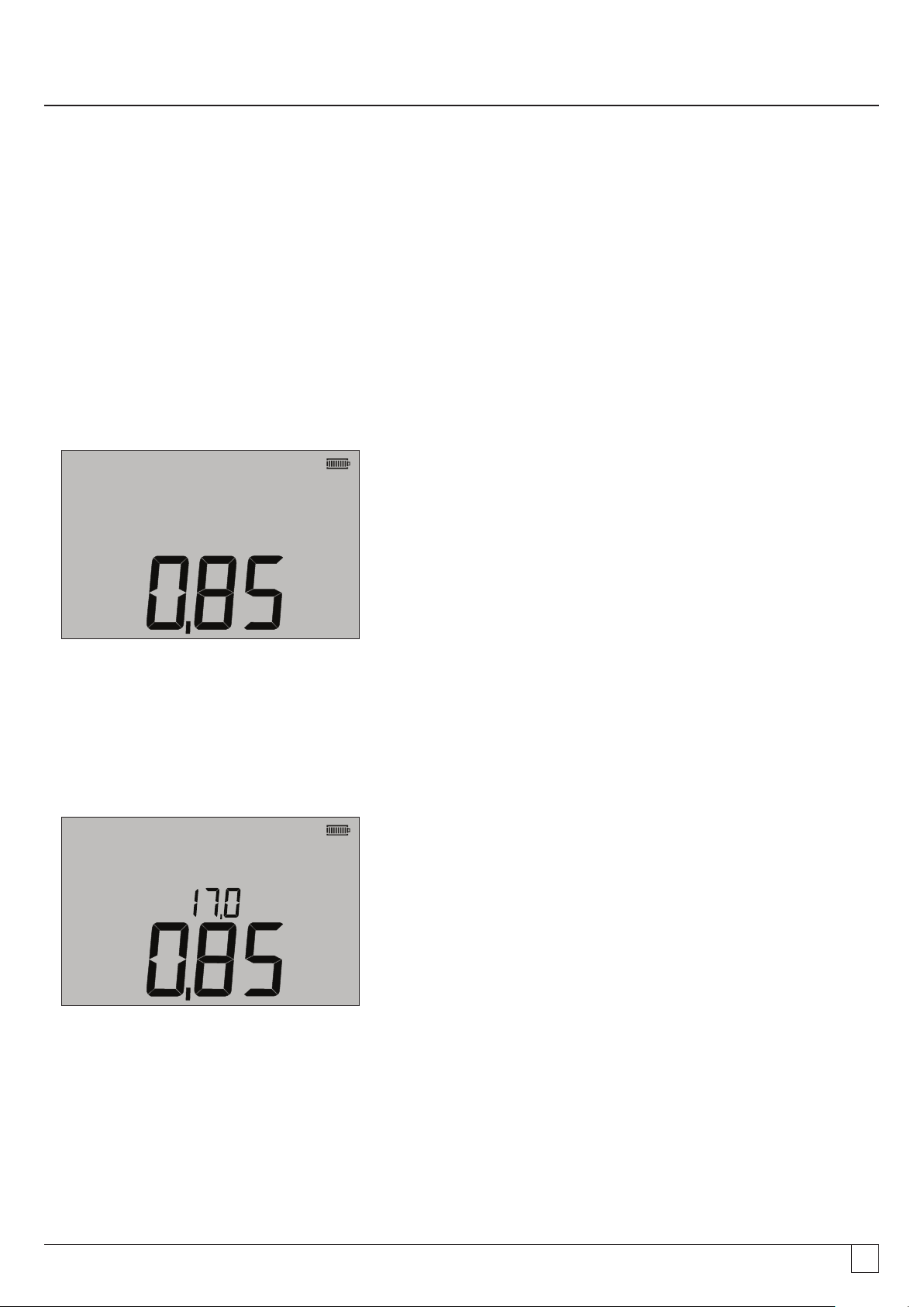
4. The display will show the capacitance value of the circuit or component under test, as below:
F
µ
- Figure 37
11.2 Distance measurement by capacitance
For the MIT481/2 and MIT485/2 instrument, it is possible to measure cable length by capacitance in either feet or km, depending on
the SETUP status.
This is an automatic function and is calculated from the stored capacitance value based on the default value of 50 nF/km). This can be
adjusted in SETUP between 40 nF/km and 70 nF/km.
The result is displayed as below:
m
k
F
µ
- Figure 38
11.3 Capacitance measurement procedure (3 terminals)
See section 7.3
www.megger.comMIT400/2
30
Page 31
12. Saving, recalling and downloading test results.
(MIT420/2, MIT430/2, MIT481/2, MIT485/2 and MIT2500)
12.1 Saving test results
After completing any test, the result remains displayed on the screen for one minute. During this time the result may be saved in
memory and recalled later.
Procedure for storing test results:
1. After completion of a particular measurement, ensure the test result is displayed on the large digital readout in the instrument
display, as below:
2 00
0
W
k
6 004 00
8 00
100 0
Am
z
W
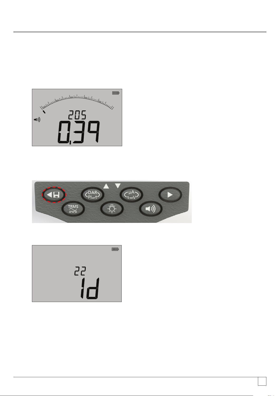
2. Example of continuity result
3. The test result will remain displayed for one minute during which time the result may be stored.
4. Press the STORE key to record the test result.
A unique identification number is allocated to each test result which is displayed for 15 seconds before returning to the test
result.
- Figure 39
- Figure 40
5. Result is now stored.
- Figure 41
www.megger.comMIT400/2
31
Page 32

12.2 Test results recall
(MIT420/2, MIT430/2, MIT481/2, MIT485/2 and MIT2500)
All stored test results may be recalled to the screen.
1. Turn the instrument ‘ON’ by rotating the selector switch to the recall (RCL) position.
2. The latest unique test result identification number will be displayed.
Where no results have previously been stored, the display will indicate this by three dashes.
3. Press [OK] to display last stored result, or select the particular test result identification number by using the UP and DOWN
buttons as below:
- Figure 42
then press ‘OK’ to select.
4. The test result will be displayed. Additional information stored with the test result may be viewed using the relevant button.
For example on insulation test µA can be recalled using the µA/S/V key. The TRMS key will operate on voltage results.
- Figure 43
PI and DAR recall.
Additional recall information is available if the result stored was a PI or DAR test, as the result is a ratio of two measured values.
To recall a PI or DAR result:
1. Rotate the selector switch to the recall
2. Locate the particular test result identification number by using the UP and DOWN buttons, then press ‘OK’ to select.
3. The test result will be displayed.
To scroll through the different measurements used in calculating the PI or DAR ratio, use the DOWN only button.
position and observe the latest unique test result identification number displayed.
www.megger.comMIT400/2
32
Page 33

12.3 Deleting test results
(MIT420/2, MIT430/2, MIT481/2 and MIT485/2 only)
Stored test results may be deleted singularly or all together.
Procedure for deleting a single test result
1. Turn the instrument ‘ON’ by rotating the selector switch to the delete position.
2. The latest test result will be displayed. Where no results have previously been stored, the display will indicate this by three
dashes.
3. Press ‘OK’ to delete the displayed test result.
4. Observe the ‘new’ last test result identification number, which may be deleted as previously described.
Procedure for deleting all test results
1. Turn the instrument ‘ON’ by rotating the selector switch to the delete position. The latest test result will be displayed.
Where no results have previously been stored, the display will indicate this by three dashes.
2. Press the LEFT or RIGHT ARROW button. Note that the display now indicates ‘ALL’
3. Press ‘OK’ to delete all the test results. Note, for large amounts of data the progress bar decays as the contents of memory are
deleted.
4. On completion of the deletion progress the display indicates three dashes signifying that no result remains stored.
12.4 Downloading test results
Preparing your MIT430/2 or MIT485/2 for “Bluetooth®” Communications.
®
“Megger Download Manager” software and a computer with “Bluetooth
and MIT485/2 instruments.
The following stages need to be implemented before the MIT can download data to a PC:
®
1. The MIT must be paired to a PC using a Bluetooth
2. Megger Download Manager software must be installed on the destination PC
Megger “Download Manager” can be installed from the supplied CD or downloaded from the Megger web site. Follow the on-screen
installation instructions during installation process.
wireless network.
” capabilities are required to communicate with MIT430
12.5 Procedure for pairing you MIT to the PC
1. Switch the MIT range knob to the PC position.
®
2. After a while, the display will show the Bluetooth
of its MAC address will be shown. If the instrument has never been paired with a PC, the display will show “---“ as below:
home screen. if there is a PC already being paired, the last three characters
www.megger.comMIT400/2
33
Page 34

- figure 44
Pre-paired screen Unpaired screen
The MIT can pair with up to 12 devices, after which further pairing will over-write the currently displayed pair.
To select a different paired device from that shown, use the UP/DOWN arrow keys.
If the MIT is already paired to the PC, go to (12.6) below.
3. Press and hold the yellow TEST button for longer than 1 second to start the pairing process.
- Figure 45
4. The instrument will search for Bluetooth® devices nearby. Once the search has been completed, the partial address of the
first detected device will be shown on the top part of the display and number “1”, the index of it, on the bottom part of the
display.
5. Use the
Manager (Accessed by right clicking on the MIT430 driver and selecting ‘properties’ then the ‘Bluetooth
and buttons to scroll through the partial address until one matches the Bluetooth® device ID in Download
®
’ tab) on PC.
6. With the required address displayed (the three digital code should match the one displayed on the properties screen on PC),
pair the instrument by pressing and holding the TEST button until the “[ ]” symbols appear on the display.
®
7. On your PC, a message bubble may appear showing that a Bluetooth
8. Click on this message and enter the passkey ‘1234’ to accept the connection. When complete the instrument display will
return to the Bluetooth
®
home screen showing the partial address of the PC being paired with.
device is trying to connect.
9. Press the TEST button to send the data to the paired PC or press and hold it for longer than 1 second to do pairing again.
10. To Delete a pair, press and hold down the LOCK [OK] button for 2 seconds.
12.6 Downloading data to the PC
1. Ensure Download Manager is running on the PC.
2. Ensure the MIT is paired to the PC as above.
3. Select the “MEGGER MIT400-2 Series” icon in Download Manager, as below:
www.megger.comMIT400/2
34
Page 35

- Figure 46
4. Select the Blue download button. The Download dialog box will be displayed.
- Figure 47
5. Turn the MIT rotary knob to the PC position.
6. Press the TEST button on the MIT to commence the download.
7. On completion of the download the MIT will display “End”. A CSV file will appear in the Download manager window. This can
be opened using:
The Megger CSV viewer
A proprietary CSV viewer
Windows
®
XLS (opens with no header conversion. Consequently the headers may not be easily interpreted)
as would be the case using Megger CSV viewer.
Further information on the options for Megger Download Manager can be found in the Download manager help files in the
application.
www.megger.comMIT400/2
35
Page 36

13. SETUP Configuration options
Operator SETUP allows the MIT to be customised to suite application or operator preferences.
To enter SETUP, select the option with the rotary knob. The following options are available:
13.1 SETUP navigation
1. Press the TEST button to scroll through the SETUP options.
2. When the display shows the required SETUP option, press the UP or DOWN arrows to change the value for that option.
The LOCK symbol will flash to indicate the value has been changed from the saved setting.
3. Press the LOCK button to store the new value
4. When all SETUP functions have been configured to the desired values, turn the rotary knob away from the SETUP setting.
Display message Function Options Factory setting
bu2 Buzzer threshold
< Limit = buzz
Loc Insulation Lock enable/disable On = INS lock enabled
ISc Continuity short circuit current
InS Insulation limit alarm threshold BMM80F/2, BM50/2, MIT410TC/2, MIT400ESD/2,
SEtV Variable insulation test voltage MIT485/2 :- 50 V - 500 V 10 V
1, 2, 3, 4, 5, 10, 20, 30, 40, 50, 100, 200
OFF = INS lock disabled
200 mA = (up to 10 W)
20 mA
MIT400E/2, MIT405/2, MIT415/2, MIT417/2:
0.5, 10, 20, 50, 100, 200, 500, 1000 MW
MIT400/2, MIT410/2, MIT420/2, MIT430/2,
MIT481/2, MIT485/2, MIT2500: 0.5, 1, 2, 3, 4,
5, 10, 20, 30, 40, 50, 100, 200, 300, 400, 500,
1000 MW
2 W
On
200 mA
0.5 MW
MIT420/2 and MIT430/2 :- 50 V - 1000 V 10 V
MIT2500 :- 50 V - 2500 V 100 V
t INS count down timer 1,2,3,4,5,6,7,8,9,10 minutes 1 min.
CAb Cable capacitance / km 40 to 60 nF/km 50 nF/km
bLt Backlight timer 20, 60, OFF (OFF = no auto off) 20 secs
SLt Sleep timer 10, 20, 30, 60, OFF (OFF = no auto off) 10 mins
HuF REN (Telephone handset)
calculator
tLu Terminal Lockout voltage 25, 30, 50, 75 50 volts
REV Auto reversal of continuity On/OFF OFF
ESd Enable the 104, 105, 106 etc
display range
bAt Battery voltage 1.2 V / 1.5 V (All Models) 1.5 V
RSt Restore factory settings Restore No
LAng Display of either Tip-Ground-Ring
or A-E-B LCD symbology
dis Distance by uF m, ft m
0.5, 0.6, 0.7, 0.8, 0.9, 1.0,1.1, 1.2, 1.3uF 1.0 uF
MIT400ESD:- On/OFF OFF
US, EU US
www.megger.comMIT400/2
36
Page 37

14. Technical Specifications
All quoted accuracies are at +20 °C.
Insulation:
Test voltage Nominal:
MIT400/2 250 V, 500 V, 1000 V
MIT410/2, 420/2,430/2 50 V, 100 V, 250 V, 500 V, 1000 V
Insulation accuracy 50 Volts. 10 GW ± 2% ± 2 digits ± 4.0% per GW
100 Volts. 20 GW ± 2% ± 2 digits ± 2.0% per GW
250 Volts. 50 GW ± 2% ± 2 digits ± 0.8% per GW
500 Volts. 100 GW ± 2% ± 2 digits ± 0.4% per GW
1000 Volts 200 GW ± 2% ± 2 digits ± 0.2% per GW
Service Error: BS EN 61557-2 (2007)
50V, ±2.0% ±2d, 100kΩ - 900kΩ ± 10.5%
100V, ±2.0% ±2d, 100kΩ - 900kΩ ± 10.3%
250V, ±2.0% ±2d, 100kΩ - 900kΩ ± 10.3%
500V, ±2.0% ±2d, 100kΩ - 900kΩ ± 10.3%
1000V, ±2.0% ±2d, 100kΩ - 900kΩ ± 11.5%
Display range Analogue:
1 GW full scale
Resolution 0.1 kW
Short circuit/charge current 2 mA +0% -50% to
EN 61557-2 (2007) (except MIT2500: 1 mA into 2.5 MW)
Open circuit voltage insulation -0% +20% ± 1V
Test current 1 mA at min. pass value of insulation to a maximum of 2 mA max.
Leakage 10% ± 3 digits
Voltage 3% ± 3 digits ± 0.5% of rated voltage
Timer control 6 0 second countdown timer
Guard terminal performance <5% error at 500 kW
Note (1) Above specifications only apply when high quality silicone leads are being used.
Continuity:
Continuity measurement 0.01 W to 999 kW (0 to 1000 kW on analogue scale)
Continuity accuracy ± 3% ± 2 digits (0 to 100 W )
Service Error: BS EN 61557-4 (2007) - ±2.0%, 0.1Ω - 2Ω ± 6.8%
Open circuit voltage 5 V ± 1 V
Test current 200 mA (–0 mA +20 mA) (0.01 W to 4 W)
Polarity Single polarity (Default) / Dual polarity (configurable on setup).
Lead resistance Null up to 9.00 W
Voltage:
Voltage range AC: 10 mV to 600 V TRMS sinusoidal (40 Hz to 400 Hz)
DC: 0 to 600 V
Voltage range accuracy AC: ±2% ±1 digit 0 to 1000 V on Analogue scale
DC: ±2% ±2 digit
Service Error: BS EN 61557-1 (2007) - ±2.0% ±2d, 0V - 300Vac/dc ± 5.1%
Waveform Unspecified range: 0 – 10 mV (40 to 400 Hz)
For non-sinusoidal waveforms additional specifications apply
Non-sinusoidal waveforms: ±3% ± 2 digits >100 mV to 600 V TRMS
±8% ± 2 digits 10 mV to 100 mV TRMS
www.megger.comMIT400/2
37
Page 38

Frequency:
Frequency measurement range 45-450Hz
Frequency measurement accuracy ±0.5% ± 1digit (100 Hz to 450 Hz) unspecified
Capacitance measurment:
MIT420/2, MIT430/2
Capacitance measurement: 100 pF to 10 μF
Capacitance measurement accuracy ± 5.0% ± 2 digits
Storage:
Result storage (MIT420 & MIT430):
Storage capacity >1000 test results
®
Data download Bluetooth
Bluetooth® Class II
Range up to 10 m
Power supply 6 x 1,5 V cells type IEC LR6 (AA, MN1500, HP7, AM3 R6HP)
Alkaline NiMH rechargeable cells may be used
Battery life 3000 insulation tests with duty cycle of 5 sec ON /55 sec OFF @ 1000 V into 1 MW
Charger (Optional): 12-15 V dc (accessory interface)
Dimensions Instrument 228 mm x 108 mm x 63 mm
(9.00 in x 4.25 in x 2.32 in)
Weight 600 g (MIT400/2), (28.74 oz )
815 g (MIT2500) (27.22 oz)
Weight (instrument and case) 1.75 kg (3.86 lb)
Fuse Use only 2 x 500 mA (FF) 1000 V
32 x 6 mm ceramic fuse of high breaking capacity HBC 10 kA minimum.
Glass fuses MUST NOT be fitted.
Safety protection The instruments meet EN 61010- 1 (1995) to 600V phase to earth, Category IV.
Refer to safety warnings supplied.
EMC In accordance with IEC 61326 including amendment No.1
Temperature co-efficient <0,1% per °C up to 1 GW
<0,1% per °C per GW above 1 GW
wireless
Environmental:
Operating temperature range and humidity -10 to +55 °C
90% RH at 40 °C max.
Storage temperature range -25 to +70 °C
Calibration temperature +20 °C
Maximum altitude 2000 m
IP rating IP 54
www.megger.comMIT400/2
38
Page 39

15. Battery and fuse replacement
15.1 Battery condition and replacement
The battery condition indicator is displayed at all times that the instrument is switched on, as below: 100%, 75%, 50%, 25% and
low, as below:
100% 75% 50% 25% Low
Replacement battery types are:
6 x LR6 (AA), 1.5 V Alkaline,
or 6 x 1.2V NiMH
WARNING: Do NOT use AA size LiON (Lithium Ion) rechargeable cells as these are 3.4V each and could permanently
damage the instrument.
Note: NiMH rechargeable batteries show a lower charge than Alkaline batteries, and may not give much warning before becoming
exhausted.
15.2 Procedure to replace batteries:
1. Switch off the instrument and disconnect the instrument from any electrical circuits.
2. Disconnect all test leads from the instrument.
3. To remove the rear cover, remove the screws from the rear of the battery cover, lift the cover off.
4. Remove the dead cells and refit new batteries, observing the correct polarity as marked on the battery compartment.
5. Replace the cover and retaining screws.
6. Dispose of the cells appropriately.
Warning: - Incorrect battery cell polarity can cause electrolyte leakage and damage to the instrument. If the battery
condition indicator does not show a full charge, a cell may be reversed.
Charging with a reversed cell can cause localised heating and possible damage to the case.
Battery cells should not be left in an instrument which may remain unused for an extended period.
15.3 Battery disposal
Instructions on the safe removal of batteries can be found in this document.
Batteries in this product are classified as portable batteries under the Batteries Directive and when spent, should be disposed of in the
UK according to Local Authority requirements.
For disposal of batteries in other parts of the EU contact your local distributor.
Megger is registered in the UK as a producer of batteries.
Registration number BPRN00142.
www.megger.comMIT400/2
39
Page 40

15.4 Blown fuse indicator
The blown fuse indicator is shown below:
2 00
0
W
6 004 00
8 00
Am
f
100 0
z
- Figure 48
This symbol operates on the continuity [W] range. The symbol indicates that one of the fuses in the instrument has failed.
W
15.5 Fuse replacement procedure
1. Switch off the instrument and disconnect the instrument from any electrical circuits.
2. Disconnect all test leads from the instrument.
3. Remove the rear fuse cover. To remove the rear cover, remove the screw from the rear of the small fuse cover and lift the cover
off, as below:
- Figure 49
4. Both fuses should be checked for failure and replaced if faulty.
A replacement fuse must be of the correct type and rating: i.e. 500 mA (FF) H.B.C.50 kA min 1000 V (32 mm x 6 mm).
5. Replace the cover and retaining screw.
15.6 Preventive maintenance
The MIT400/2 series instruments require very little maintenance.
Test leads should be checked before use to ensure there is no damage.
Ensure batteries are removed if the instrument is left unused for an extended period.
When necessary, the instrument can be cleaned with a damp cloth.
Do not use alcohol based cleaners as these may leave a residue.
www.megger.comMIT400/2
40
Page 41

Repair and warranty
If the protection of an instrument has been impaired it should not be used, but sent for repair by suitably trained and qualified
personnel. The protection is likely to be impaired if, for example, the instrument shows visible damage, fails to perform the intended
measurements, has been subjected to prolonged storage under unfavourable conditions, or has been exposed to severe transport
stresses.
nd
New instruments are covered by a 3 year warranty from the date of purchase by the user, the 2
the free registration of the product on www.megger.com. You will need to log in, or first register and then login to register your
product. The 2
nd
and 3rd year warranty covers faults, but not recalibration of the instrument which is only warranted for one year. Any
unauthorised prior repair or adjustment will automatically invalidate the warranty.
These products contain no user repairable parts and if defective should be returned to your supplier in original packaging or packed
so that it is protected from damage during transit. Damage in transit is not covered by this warranty and replacement/repair is
chargeable.
Megger warrants this instrument to be free from defects in materials and workmanship, where the equipment is used for its proper
purpose. The warranty is limited to making good this instrument (which shall be returned intact, carriage paid, and on examination
shall disclose to their satisfaction to have been defective as claimed). Any unauthorised prior repair or adjustment will invalidate the
warranty. Misuse of the instrument, from connection to excessive voltages, fitting incorrect fuses, or by other misuse is excluded from
the warranty. The instrument calibration is warranted for one year.
This Warranty does not affect your statutory rights under any applicable law in force, or your contractual rights arising from a sale and
purchase contract for the product. You may assert your rights at your sole discretion
and 3rd year being conditional on
Calibration, Service and Spare Parts
For service requirements for Megger Instruments contact Megger or your local distributor or authorised repair centre.
Megger operates fully traceable calibration and repair facilities, ensuring your instrument continues to provide the high standard
of performance and workmanship you expect. These facilities are complemented by a worldwide network of approved repair and
calibration companies to offer excellent in-service care for your Megger products.
See the back of this user guide for Megger contact details.
Details of your Authorised Service Centre is available by contacting ukrepairs@megger.com and giving details of your location.
www.megger.comMIT400/2
41
Page 42

www.megger.comMIT400/2
42
Page 43

MEGGER LIMITED
ARCHCLIFFE ROAD
DOVER
KENT
CT17 9EN
ENGLAND
T +44 (0)1 304 502101
F +44 (0)1 304 207342
MEGGER MIDDLE EAST
PO BOX 500503 @DIC13
OFFICE 209 BLDG 14,
DUBAI INTERNET CITY,
UNITED ARAB EMIRATES
T. +971 4 443 5489
MEGGER (INDIA) PVT LIMITED
211 CRYSTAL PARADISE MALL
OFF VEERA DESAI ROAD ANDHERI (W)
MUMBAI
400 053
INDIA
T. +91 22 2674 0468
F. +91 22 2674 0465
MEGGER CANADA
UNIT 106-550
ALDEN ROAD
MARKHAM
ON L3R 6A8
CANADA
T. 416-298-6770
MEGGER USA - VALLEY FORGE
VALLEY FORGE CORPORATE CENTER
2621 VAN BUREN AVENUE
NORRISTOWN
PENNSYLVANIA,
19403 USA
T. 1-610 676 8500
F. 1-610-676-8610
MEGGER GMBH
OBERE ZEIL 2 61440
OBERURSEL,
GERMANY
T. 06171-92987-0
F. 06171-92987-19
OTHER TECHNICAL SALES OFFICES
Toronto CANADA, Sydney AUSTRALIA, Madrid SPAIN, Mumbai INDIA, and the Kingdom of BAHRAIN.
Megger products are distributed in 146 countries worldwide.
This instrument is manufactured in the United Kingdom.
The company reserves the right to change the specification or design without prior notice.
Megger is a registered trademark
MIT4002--MIT4202--MIT4302--MIT4802--MIT2500_UG_en_V01
www.megger.com
 Loading...