

Page 1

A Guide To Diagnostic
Insulation Testing Above 1 kV
TOLL FREE
CUSTOMER SERVICE NUMBER
1-866-254-0962
The word “Megger” is a registered trademark
WWW.MEGGER.COM/us
Page 2

WHY A 10 KV INSULATION TESTER?
Megger invented insulation testing before the beginning of the 20th century and has continued to lead the market in
innovation and technological advancement. So, why did we develop a 10 kV model when all other suppliers stopped at
5 kV? The answer is in the IEEE standards. Megger developed a 10 kV unit to meet the new testing recommendations
outlined by the IEEE. Megger has offered a 10 kV insulation resistance tester since 2001.
In March 2000, The IEEE-SA Standards Board approved a revision to IEEE Std 43-1974. The “IEEE Recommended Practice
for Testing Insulation Resistance of Rotating Machinery,” Std 43-2000, emphasizes the need for upgrading current
practices to accommodate changes and improvements in insulating materials and the value of higher voltage testing
that reveals otherwise hidden flaws.
Following is a brief summary of the highlights of the standard:
n
Test voltages up to 10 kV are recommended for windings rated greater than 12 kV.
n
Both the Insulation Resistance test and the Polarization Index test are recommended.
n
Test results should be compared to historical values to identify changes.
n
In lieu of historical records, minimum acceptable values (based on the type of equipment) for both tests are
indicated.
n
Depending on the machine rating, the readings for one or both tests should exceed the minimum acceptable
values.
n
If the readings are below the minimum acceptable values, the winding is not recommended for an over voltage
test or for operation.
IEEE Std 43-2000 recommends a procedure for measuring insulation resistance of armature and field windings in
rotating machines rated 1 hp, 750 W or greater and applies to synchronous machines, induction machines, dc machines
and synchronous condensers. It does not apply to fractional horsepower machines. It also recommends the insulation
test voltage (based on winding rating) and minimum acceptable values of insulation resistance for ac and dc rotating
machine windings.
For more information on the IEEE Standard, please turn to page 23 in the booklet.
Page 3

TABLE OF CONTENTS
Introduction ........................................................................2
What is Insulation? ............................................................2
What Causes insulation to Degrade? ...........................3
Electrical Stress ...........................................................3
Mechanical Stress .......................................................3
Chemical Attack .........................................................3
Thermal Stress ............................................................3
Environmental Contamination .................................3
How Can Predictive Maintenance Help Me? ...............3
The Benefit of New Technology ...................................4
How Insulation Resistance is Measured ...........................4
How an Insulation Resistance Tester Operates ...........4
Components of Test Current ........................................4
Capacitive Charging Current .....................................4
Absorption or Polarization Current ..........................4
Surface Leakage Current ...........................................5
Conduction Current ...................................................5
Connecting your Insulation Tester ...............................6
Selected Typical Connections .......................................6
Shielded Power Cable ................................................6
Circuit Breaker/Bushings ............................................6
Power Transformer ....................................................6
AC Generator .............................................................7
Insulation Resistance Tester Scale ................................7
Voltage Characteristics .................................................8
The Guard Terminal ......................................................9
Introduction ...............................................................9
How the Guard Terminal Works .............................10
Guard Terminal Performance ..................................10
The Guard Terminal as a Diagnostic Tool ..............11
Final Words ..............................................................11
Evaluation and Interpretation of Results .......................12
Interpretation of the Infinity Reading .......................12
Diagnostic High Voltage Insulation Tests ......................12
Spot Reading Test .......................................................12
Time vs. Resistance Test ..............................................14
Polarization Index Test ...............................................14
Step Voltage Test ........................................................16
Dielectric Discharge Test .............................................16
Different Problems/Different Tests ............................18
Appendices .......................................................................19
Potential Sources of Error/Ensuring Quality Test
Results ..........................................................................19
Test Leads .................................................................19
Making Measurements above 100 GΩ ...................19
Accuracy Statements ................................................19
Delivery of Stated Voltage ......................................19
Interference Rejection .............................................19
Rules on Testing and Comparing ............................20
CAT Rating ...................................................................20
CAT Rating Guidelines .............................................21
The Importance of a CAT Rating ............................21
Some CAT Rating Basic Statistics .............................21
Testing Insulation Resistance
of Rotating Machinery ................................................21
Effects of Temperature ...............................................23
Effects of Humidity .....................................................24
Ingress Protection ........................................................24
High Potential Testing ................................................26
Current (nA) Readings vs.
Resistance (MΩ) Readings .......................................26
Burn Capability ............................................................26
Drying Out Electrical Equipment ................................26
Test Item Discharge .....................................................27
Charging Time for Large Equipment .........................28
Motor Driven Insulation Testers .................................28
Megger Insulation Testers ...............................................29
MIT510/2 and MIT520/2
5-kV Insulation Testers ................................................29
MJ15 and BM15
5-kV Insulation Testers ................................................29
S1-552/2 and S1-554/2
5-kV Insulation Testers ................................................29
MIT1020/2
10-kV Insulation Tester ...............................................30
S1-1052/2 and S1-1054/2
10-kV Insulation Testers ..............................................30
A GUIDE TO DIAGNOSTIC INSULATION TESTING ABOVE 1 KV 3
Page 4

INTRODUCTION
Electrical insulation degrades over a period of time
because of various stresses, which are imposed upon it
during its normal working life. The insulation has been
designed to withstand these stresses for a period of
years, which would be regarded as the working life of
that insulation. This often runs into decades.
Abnormal stresses can bring about an increase in this
natural aging process that can severely shorten the
working life of the insulation. For this reason it is good
practice to perform regular testing to identify whether
increased aging is taking place and, if possible, to
identify whether the effects may be reversible or not.
The purpose of diagnostic insulation testing is:
n
To identify increased aging.
n
To identify the cause of this aging.
n
To identify, if possible, the most appropriate actions
to correct the situation.
In its simplest form, diagnostic testing takes the form of
a “Spot Test.” Most electrical maintenance professionals
have made spot tests where a voltage is applied to the
insulation and a resistance is measured. The diagnosis
in this case is limited to “the insulation is good” or “the
insulation is bad.” But having made this diagnosis what
do we do about it? It’s a bit like going to the doctor with
a bad cough and the doctor simply telling you, “You’ve
got a bad cough.” You wouldn’t be happy to come away
with only that information. You expect the doctor to
examine you, carry out a few tests, and tell you why you
have a bad cough and what to do about it to cure the
cough.
In insulation testing, a spot test on its own is the
equivalent of the doctor telling you that you are well
or you are sick. It’s minimal information. This is the sort
of test that is typically applied to low-voltage circuits
where the cost of a failure is low and equipment can be
replaced easily and inexpensively. Since the equipment
being tested is low voltage equipment, these tests are
typically performed using a 500 or 1000 V test voltage
and will be familiar to all electrical maintenance
personnel.
However, if the doctor records the results of his
examination and compares them with those from
previous visits, then a trend might be apparent which
could lead to medication being prescribed. Similarly,
if insulation resistance readings are recorded and
compared with previously obtained readings, it may be
possible to see a trend and to prescribe remedial actions
if such are called for.
Diagnostic insulation testing at voltages above 1 kV is an
area that is less familiar to many electrical maintenance
personnel. The purpose of this booklet, therefore, is to:
n
Acquaint the reader with making diagnostic
insulation resistance tests.
n
Provide guidelines for evaluating the results of these
diagnostic insulation resistance tests.
n
Introduce the benefits of multi-voltage testing at
higher voltages.
A series of appendices are included at the end of
the booklet to provide the reader with additional
information related to diagnostic insulation testing.
This booklet is based on the principles established in
the booklet “A Stitch in Time… The Complete Guide to
Electrical insulation Testing” first published in 1966 by
the James G. Biddle Company.
WHAT IS INSULATION?
Every electric wire in a facility, whether it’s in a motor,
generator, cable, switch, transformer, or whatever is
covered with some form of electrical insulation. While
the wire itself is a good conductor (usually made of
copper or aluminum) of the electric current that powers
electrical equipment, the insulation must resist current
and keep the current in its path along the conductor.
Understanding Ohm’s Law, which is expressed in
the following equation, is the key to understanding
insulation testing:
E = I x R
where,
E = voltage in volts
I = current in amperes
R = resistance in ohms
For a given resistance, the higher the voltage, the
greater the current. Alternatively, the lower the
resistance of the wire, the more current that flows for
the same voltage.
No insulation is perfect (has infinite resistance), so some
current does flow along the insulation or through it to
ground. Such a current may be insignificantly small for
most practical purposes but it is the basis of insulation
testing equipment.
So what is “good” insulation? “Good” means a relatively
high resistance to current flow. When used to describe
an insulation material, “good” also means “the ability
to maintain a high resistance.” Measuring resistance can
tell you how “good” the insulation is.
4 A GUIDE TO DIAGNOSTIC INSULATION TESTING ABOVE 1 KV
Page 5

What Causes insulation to Degrade?
There are five basic causes for insulation degradation.
They interact with each other and cause a gradual spiral
of decline in insulation quality.
Electrical Stress
Insulation is designed for a particular application.
Overvoltages and undervoltages cause abnormal stresses
within the insulation, which can lead to cracking or
delamination of the insulation.
Mechanical Stress
Mechanical damage such as hitting a cable while digging
a trench is fairly obvious but mechanical stresses also
may occur from running a machine out of balance
or frequent stops and starts. The resulting vibration
from machine operation may cause defects within the
insulation.
Chemical Attack
While you would expect insulation to be affected by
corrosive vapors, dirt and oil can also operate to reduce
the effectiveness of insulation.
Thermal Stress
Running a piece of machinery in excessively hot or cold
conditions will cause over expansion or contraction of
the insulation which might result in cracks and failures.
However, thermal stresses are also incurred every time
a machine is started or stopped. Unless the machinery is
designed for intermittent use, every stop and start will
adversely affect the aging process of the insulation.
Environmental Contamination
Environmental contamination covers a multitude
of agents ranging from moisture from processes, to
humidity on a muggy day, and even to attack by rodents
that gnaw their way into the insulation.
Insulation begins to degrade as soon as it is put in
service. The insulation in any given application will
have been designed to provide good service over many
years under normal operating conditions. However,
abnormal conditions may have a damaging effect
which, if left unchecked, will speed up the rate of
degradation and will ultimately cause a failure in the
insulation. Insulation is deemed to have failed if it fails
to adequately prevent electrical current from flowing in
undesirable paths. This includes current flow across the
outer or inner surfaces of the insulation (surface leakage
current), through the body of the insulation (conduction
current) or for a variety of other reasons.
For example, pinholes or cracks can develop in the
insulation or moisture and foreign matter can penetrate
the surface(s). These contaminants readily ionize
under the effect of an applied voltage providing a
low resistance path for surface leakage current which
increases compared with dry uncontaminated surfaces.
Cleaning and drying the insulation, however, will easily
rectify the situation.
Other enemies of insulation may produce deterioration
that is not so easily cured. However, once insulation
degradation has started, the various initiators tend to
assist each other to increase the rate of decline.
How Can Predictive Maintenance Help Me?
While there are cases where the drop in insulation
resistance can be sudden, such as when equipment is
flooded, it usually drops gradually, giving plenty of
warning if tested periodically. These regular checks
permit planned reconditioning prior to service failure
and/or a shock condition.
Without a periodic testing program all failures will come
as a surprise, unplanned, inconvenient and quite possibly
very expensive in time and resources and, therefore,
money to rectify. For instance, take a small motor that
is used to pump material, which will solidify if allowed
to stand, around a processing plant. Unexpected failure
of this motor will cost tens maybe even hundreds
of thousands of dollars to rectify if downtime of
the plant is also calculated. However, if diagnostic
insulation testing had been included in the preventive
maintenance program it may have been possible to plan
maintenance or replacement of the failing motor at
a time when the line was inactive thereby minimizing
costs. Indeed, it may have been that the motor could
have been improved while it was still running.
If advanced insulation degradation goes undetected
there is an increase in the possibility of electrical shock
or even death for personnel; there is an increase in the
possibility of electrically induced fires; the useful life
of the electrical equipment can be reduced and/or the
facility can face unscheduled and expensive downtime.
Measuring insulation quality on a regular basis is a
crucial part of any maintenance program as it helps
predict and prevent electrical equipment breakdown.
This is particularly appropriate now when we consider
that large parts of the electrical network in the USA and
Europe were installed in the 1950s in a burst of postwar
investment. Some equipment is approaching the end of
its design life, while some has already exceeded it but is
still operating satisfactorily.
A GUIDE TO DIAGNOSTIC INSULATION TESTING ABOVE 1 KV 5
Page 6

Since diagnostic testing is generally reserved for more
critical items we normally, but not always, find that
diagnostic testers have voltage outputs of 5 or 10 kV,
these voltages being more suitable for testing the assets
which themselves are usually medium voltage machines,
cables, transformers, etc.
The Benefit of New Technology
Insulation testers date back to the early 20th century
when Sidney Evershed and Ernest Vignoles developed
their first insulation tester (which developed in 1903
into the Megger
®
range of testers).
In the early days, most instruments were hand-cranked.
This limited their ability to carry out tests which took
an extended time to complete, and limited the voltage
stability to the operator’s ability to crank steadily.
Later, these same instruments were capable of having
an external motor drive added which helped with long
duration tests but did very little to improve the voltage
stability. However, the range of these instruments rarely
exceeded 1000 MΩ. The analog movements were very
heavy and actually served to damp out any transient
events.
The appearance of electronics and the development
of battery technology revolutionized the design of
insulation testers. Modern instruments are line or
battery-powered and produce very stable test voltages
under a wide variety of conditions. They are also able
to measure very small currents so that their insulation
resistance measuring range is extended several
thousandfold into the teraohm (TΩ) range. Some
can even replace the pencil, paper and stopwatch,
which were formerly used to manually collect results,
by recording data in memory for later download
and analysis. It is fortunate that these astonishing
enhancements were made since the manufacturers of
insulating material have been working hard also, with
the result that modern insulating materials now exhibit
much higher resistances than those in the early 20th
century.
Newer technology offers enhanced performance so
that established procedures can yield greater insights
and new methods can be made available. Modern
instruments deliver stable voltage over their full
resistance range, with microprocessor sensitivity in the
measuring circuit enabling measurements in the TΩ
range. The combination of stable voltage and enhanced
sensitivity enables the tester to measure the minuscule
amounts of current that are passed by quality insulation
in new, capital equipment. Accordingly, sophisticated
procedures that rely on precise measurement have been
developed and may be easily implemented.
Now that the insulation tester isn’t limited to values
associated with faulty or aged equipment, it can be
used to pinpoint the test item’s position anywhere
along its aging curve. The “infinity” indication that is a
delight to the repair technician represents a void to the
diagnostician. Some instruments have diagnostic tests
preprogrammed into their software and can run them
automatically, filling that void with valuable analytical
data.
HOW INSULATION RESISTANCE IS MEASURED
How an Insulation Resistance Tester Operates
The Megger® insulation tester is a portable instrument
that provides a direct reading of insulation resistance
in ohms, megohms, gigohms, or teraohms (depending
on the model chosen) regardless of the test voltage
selected. For good insulation, the resistance usually reads
in the megohm or higher range. The Megger insulation
tester is essentially a high-range resistance meter
(ohmmeter) with a built-in dc generator.
The instrument’s generator, which can be hand-cranked,
battery or line-operated, develops a high dc voltage
that causes several small currents through and over
surfaces of the insulation being tested. The total current
is measured by the ohmmeter, which has an analog
indicating scale, digital readout or both.
Components of Test Current
If we apply a test voltage across a piece of insulation,
then by measuring the resultant current and applying
Ohm’s Law (R=E/I), we can calculate the resistance of the
insulation. Unfortunately, more than one current flows,
which tends to complicate matters.
Capacitive Charging Current
We are all familiar with the current required to charge
the capacitance of the insulation being tested. This
current is initially large but relatively short lived,
dropping exponentially to a value close to zero as the
item under test is charged. Insulating material becomes
charged in the same way as a dielectric in a capacitor.
Absorption or Polarization Current
Absorption current is actually made up of up to three
components, which decay at a decreasing rate to a value
close to zero over a period of several minutes.
The first is caused by a general drift of free electrons
through the insulation under the effect of the electric
field.
6 A GUIDE TO DIAGNOSTIC INSULATION TESTING ABOVE 1 KV
Page 7
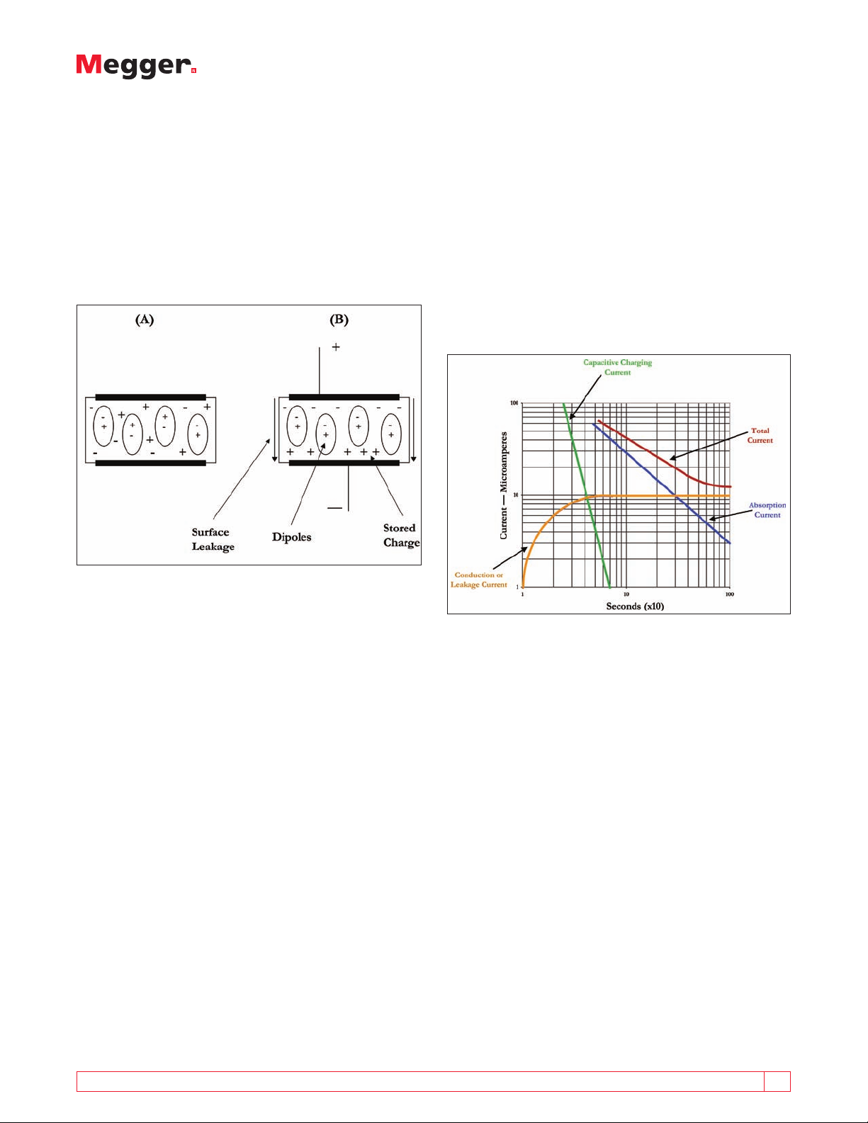
The second is caused by molecular distortion whereby
the imposed electric field distorts the negative charge of
the electron shells circulating around the nucleus toward
the positive voltage.
The third is due to the alignment of polarized molecules
within the electric field applied. This alignment is fairly
random in a neutral state, but when an electric field is
applied, these polarized molecules line up with the field
to a greater or lesser extent.
Conduction Current
Conduction current is steady through the insulation
and is usually represented by a very high value resistor
in parallel with the capacitance of the insulation. It
is a component of the Leakage Current, which is the
current that would be measured when the insulation is
fully charged and full absorption has taken place. Note
that it includes surface leakage, which can be reduced
or eliminated by the use of the guard terminal (to be
discussed later).
The graph in Figure 2 shows the nature of each of the
components of current with respect to time.
Figure 1: Alignment of Polarized Molecules
The three currents are generally considered together as
a single current and are mainly affected by the type and
condition of the bonding material used in the insulation.
Although the absorption current approaches zero, the
process takes much, much longer than with capacitive
current.
Orientational polarization is increased in the presence
of absorbed moisture since contaminated materials
are more polarized. This increases the degree of
polarization. Depolymerization of the insulation also
leads to increased absorption current.
Not all materials possess all three components and,
indeed, material such as polyethylene exhibits little, if
any, polarization absorption.
Surface Leakage Current
The surface leakage current is present because the
surface of the insulation is contaminated with moisture
or salts. The current is constant with time and depends
on the degree of ionization present, which is itself
dependent on temperature. It is often ignored as a
separate current, being included with the conduction
current below as the total leakage current.
Figure 2: Components of Test Current
The total current is the sum of these components.
(Leakage current is shown as one current.) It is this
current that can be measured directly by a microammeter
or, in terms of megohms, at a particular voltage by
means of a Megger insulation tester. Some instruments
offer the alternatives of displaying a measurement in
terms of current or as a resistance.
Because the total current depends upon the time
that the voltage is applied, Ohm’s Law (R = E/I) only
holds, theoretically, at an infinite time (that implies
waiting forever before taking a reading). It is also
highly dependent upon starting from a base level of
total discharge. The first step in any insulation test is,
therefore, to ensure that the insulation is completely
discharged.
A GUIDE TO DIAGNOSTIC INSULATION TESTING ABOVE 1 KV 7
Page 8
Please note: The charging current disappears
relatively rapidly as the equipment under test
becomes charged. Larger units with more
capacitance will take longer to be charged. This
current is stored energy and, for safety reasons,
must be discharged after the test. Fortunately,
the discharge of this energy takes place relatively
quickly. During testing, the absorption current
decreases at a relatively slow rate, depending upon
the exact nature of the insulation. This stored
energy, too, must be released at the end of a test,
and requires a much longer time to discharge than
the capacitance charging current.
Connecting your Insulation Tester
With modern insulating materials there is little, if
any, difference in the reading obtained, regardless of
which way the terminals are connected. However, on
older insulation, a little known phenomenon called
electroendosmosis causes the lower reading to be
obtained with the positive terminal connected to the
grounded side of the insulation being tested. If testing
an underground cable, the positive terminal would
normally be connected to the outside of the cable since
this will be grounded by contact with the soil, as shown
in Figure 3. Please note that you do not connect directly
to the insulation but rather to the cable’s neutral or
ground.
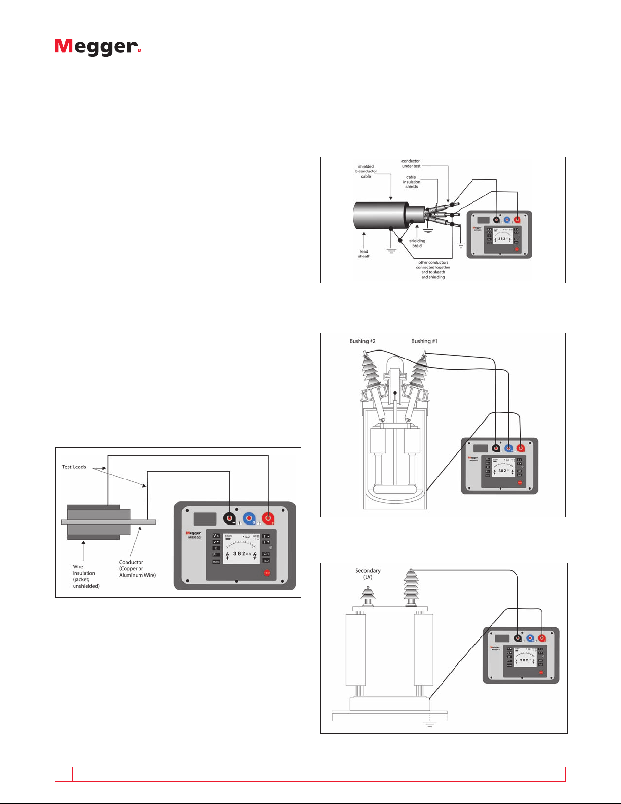
Selected Typical Connections
Shielded Power Cable
Connected to measure the insulation resistance between
one conductor and ground.
Figure 4: Connection to a Shielded Power Cable
Circuit Breaker/Bushings
Figure 3: Simplistic Connection to a Cable
8 A GUIDE TO DIAGNOSTIC INSULATION TESTING ABOVE 1 KV
Figure 5: Connection to a Circuit Breaker
Power Transformer
Figure 6: Connection to a Power Transformer
Page 9
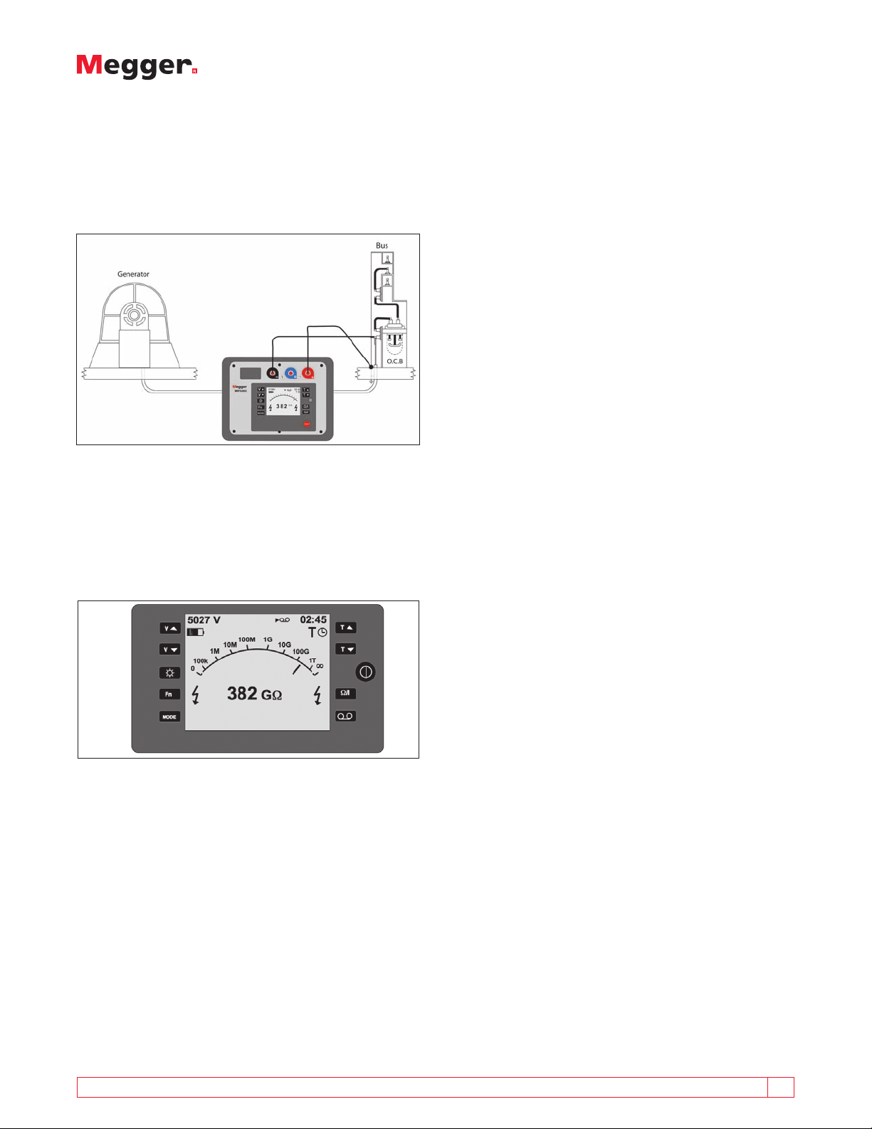
AC Generator
Keen observers will note that the hookup to measure
the circuit breaker bushing included the connection of
the third, or Guard, terminal. The use of this terminal is
explained in greater detail later in this booklet.
Figure 7: Connection to an AC Generator
Insulation Resistance Tester Scale
Most modern insulation testers offer displays that
provide the operator with both a digital readout of the
result and some form of analog readout. Figure 8 is a
representation of the Megger MIT520/2 display.
nearly impossible to discern from the dancing digits of
an LCD. A few examples are listed here:
n
As the test voltage increases and the item under
test approaches breakdown, corona discharge
will cause the pointer to “jitter,” indicating to the
operator that the maximum voltage that the item
can withstand is being approached. This warning
happens in time to terminate the test before actual
breakdown, and possible damage, occurs.
n
To the experienced operator, the speed at which
the pointer travels imparts information on the
capacitance of the item under test. This is a useful
property in high-voltage cable testing, and relates
to the theoretical basis of the more sophisticated
dielectric discharge test that is described elsewhere
in this booklet.
n
If the pointer alternately rises and drops back, it
could indicate arcing in the item under test that is
too small to cause the automatic shutdown of the
tester. Such information helps direct the operator in
pinpointing a problem.
n
Observing a pointer as it slows to an apparent halt
(it may still be moving, but at a “speed” likened
to that of a clock hand) can be more agreeable to
taking a quick or spot reading than trying to decide
when a digital display has reasonably stabilized.
No digital display “freezes” on a precise number
without at least some fluctuation of the least
significant digit.
Figure 8: Megger MT520/2 Display
When an insulation tester is “hooked up” to the item to
be tested, and a test is started, several things occur. The
three different currents, capacitive charging, dielectric
absorption, and conduction/leakage are flowing. The sum
of these three currents will cause the instrument display
to vary with the reading increasing, initially quickly and
then more slowly with time.
With an analog display, the movement of the pointer
may provide information to an experienced operator.
Is the pointer traveling smoothly, or “stuttering?” Is
it rising steadily or intermittently dropping back? This
valuable supplementary information would be difficult or
This kind of detail is difficult or impossible for the eye to
extract from the scrolling digits on an electronic display.
But whereas pointer travel may be desirable, when it
stops, the operator is left to interpolate the reading
between the scale markings, introducing an element of
judgment, which can be a source of error. Digital models
present no such problem, as they inform the operator
exactly (within the unit’s accuracy specification) what
measurement has been taken. And remember, most will
give you a value of capacitance at the end of the test.
Most Megger insulation testers above 1 kV come with
an analog/digital display. One of the advantages of
this display is that the analog portion of the meter
will sway and oscillate, indicating to the operator that
the item under test has not yet reached a steady state
and is still under the influence of the absorption and
charging current. This indication means that the item
should be tested longer or that there is a problem. When
the analog portion of the display becomes steady, the
instrument displays the result in an unambiguous digital
direct reading form, with no multipliers or math to
perform.
A GUIDE TO DIAGNOSTIC INSULATION TESTING ABOVE 1 KV 9
Page 10
Unlike the analog/digital display mentioned above, an
“average sensing” bar graph meter does not provide
a real-time indication of insulation resistance. Some
instruments offer a curved bar graph in place of a
genuine logarithmic arc, in which the low end of the
scale is expanded relative to the high end. The bar graph
takes readings over time, performs calculations and
then displays the results. The problem with this type
of meter is its principal of operation. If an event occurs
when the bar graph is not taking readings, it will be
missed and not shown on the display. Additionally, bar
graph simulations of pointer travel may not appear to
the eye the same as the familiar pointer travel and may
not replicate a mechanical movement to the expected
degree.
When doing insulation testing, the more the operator
knows about the results (during and after the test), the
better his/her decision on how to correct the problem, if
one exists. If something is missed during a test because
the instrument had a bar graph style meter, important
information could also be missed.
Voltage Characteristics
The output voltage of an insulation tester depends on
the resistance it is measuring. At low resistances, say tens
of ohms, the output voltage will be close to zero, maybe
a few volts. As the resistance load is increased so the
test voltage will increase until it reaches the requested
voltage. As the resistance increases further, the test
voltage will slowly increase until a steady value is
reached. This value will probably be slightly in excess of
the requested nominal voltage (e.g. 5104 V when 5000 V
was selected).
You should always ensure that an insulation tester is
provided with a “load graph” that indicates output
voltage characteristics against load resistance or,
alternatively, an integral voltmeter that actually
measures the terminal voltage during a test and displays
it continuously. By this means you can ensure that an
adequate voltage is produced over the resistance range
of interest.
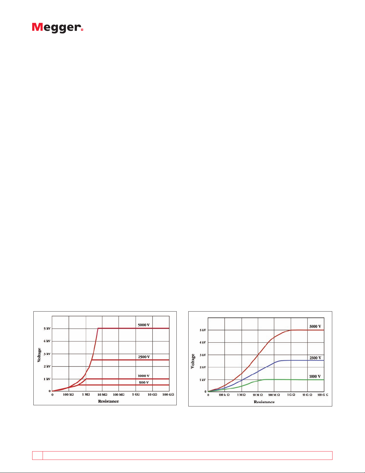
A quality insulation tester will have a voltage
characteristic that exhibits a sharp rise in voltage up to a
level of resistance commensurate with good insulation.
A fast rise time ensures an effective measurement. The
voltage characteristic shown in Figure 9 represents a
good characteristic. In this example, the output voltage
will have reached 500 V at a load as low as 500 kΩ
and 1000 V by 1 MΩ. These values are legislated by
international standards for testing wiring in houses,
shops, etc. While this is hardly a typical use for typical
diagnostic insulation testers, it does provide a good
benchmark for the serious manufacturer. Similar figures
would apply at higher voltages. Voltage should rise
sharply up to anywhere from one to five megohms,
depending on the voltage selection, and maintain that
voltage at all higher resistances.
With lower quality insulation testers, voltage ramp is
far slower. The instruments typified by the poor curve
shown in Figure 10 do not produce the rated voltage
until much higher resistances have been reached. Thus
tests could produce results that provide pass levels of
insulation but have only been subjected to half the
desired test voltage.
Figure 9: Good Load Curve
10 A GUIDE TO DIAGNOSTIC INSULATION TESTING ABOVE 1 KV
Figure 10: Poor Load Curve
Page 11
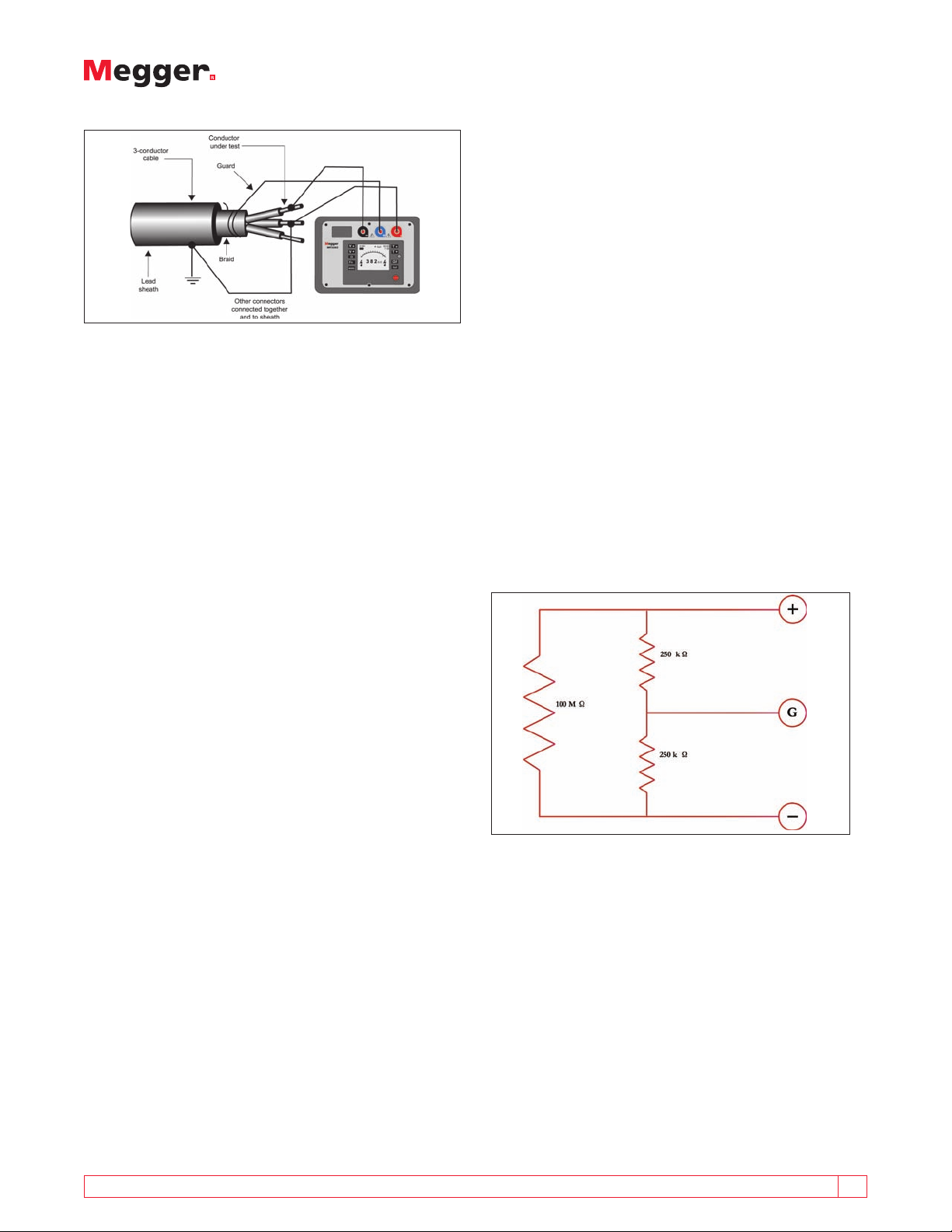
Figure 11: Use of the Guard Terminal on a Power Cable
The Guard Terminal
Introduction
When making an insulation test, we are often so
preoccupied with the resistance of the actual insulator
that we forget the resistance path on the outer
surface of the insulating material. This resistance path
can be very much part of our measurement and can
dramatically affect the results.
As a refresher, the total current that flows during an
insulation resistance test is made up of three main
components:
1. The charging current, which is charging up the
object’s capacitance.
circuit that diverts surface leakage current around
the measurement function. If parallel leakage paths
exist, a guard connection will eliminate those from the
measurement, and give a more precise reading of the
leakage between the remaining elements.
Surface leakage is essentially a resistance in parallel
with the true insulation resistance of the material being
tested. When making a two-terminal measurement, this
resistance path is very much part of the measurement
and can effect the readings dramatically. A threeterminal measurement, which includes the use of the
guard terminal, ignores the surface leakage. This can be
quite important when testing high voltage components
like Insulators, bushings and cables where high
resistance values are expected.
As an example, dirt and moisture on a transformer
bushing will promote surface leakage between the +
and – connections, thereby bringing down the reading
and possibly giving a false impression that the bushing is
defective. Connecting the guard to a bare wire wrapped
around the bushing will intercept this current and yield
a measurement based predominantly upon leakage
through defects in the ceramic.
2. An absorption current, which is the current that is
being drawn into the insulation by the polarizing of
the electrons; initially high but drops over time (at a
rate slower than the charging current).
3. The conduction or leakage current, which is the
small, steady state current that divides into two
parts:
a. The conduction path through the insulation.
b. The current flowing over the surface of the
insulation.
The current flowing over the surface is the component
of current that we do not want to measure if we want
to measure the insulation resistance of the material.
Surface leakage introduces errors into the measurement
of insulation resistance. Removing the surface leakage
from the measurement becomes more critical the higher
the expected insulation resistance values.
Some insulation testers have two terminals, others have
three. As these are dc testers, two of the terminals are
the + and -. The third (if present) is a guard. It does
not have to be used and many operators use insulation
testers satisfactorily without ever employing the guard.
However, it affords the operator an extra function for
diagnosis of equipment problems. The guard is a shunt
Figure 12: Guard Terminal Diagram
It is most important not to confuse the guard with a
ground. Connecting the guard and return lead to the
same element of the test item only shunts the current
that is supposed to be measured, and thereby shortcircuits the measurement function. When selecting a
tester, consider:
n
The goals of testing (basic installation checks don’t
generally require a guard).
n
The electrical composition of the items to be
tested (motors and transformers can be tested for
leakage between windings, with ground leakage
eliminated).
A GUIDE TO DIAGNOSTIC INSULATION TESTING ABOVE 1 KV 11
Page 12

n
The possible effects of surface leakage (wire and
cable can carry current across the surface, via dirt
and moisture, as well as through the insulating
material).
n
The degree to which results must be analyzed (are
“bad” items merely to be replaced or discarded,
or will it be necessary to localize faults for possible
repair).
How the Guard Terminal Works
The following high voltage bushing example shows
a typical application for the guard terminal. In the
first graphic, the guard terminal is not used and the
leakage current flowing through the bushing and across
the surface is combined and measured together by
the instrument. In the second graphic, wire has been
wrapped around the bushing and connected to the
guard terminal so that the surface leakage flows to the
guard terminal. Current flowing into the guard terminal
is not measured by the instrument, meaning that it is
ignored in the insulation resistance measurement.
Guard Terminal not being used
To better understand what is actually happening
within the instrument, consider the following diagram.
The insulation tester has three main elements; the
high voltage dc current source, the high voltage
voltmeter and the current meter. The insulation
resistance measurement is simply Ohm’s Law, measured
voltage divided by the measured current. The guard
terminal allows leakage current to bypass the current
measurement and be ignored.
Guard Terminal Performance
Testers with guards generally cost a bit more than
two-terminal models, but in many applications, a twoterminal model won’t be imparting the full spectrum of
information that can be accrued by insulation testing.
Something that is often forgotten is the difference in
the capabilities of the guard circuit. Guard terminal
performance is often hidden in the instrument datasheet
or left out altogether. The guarding capability of
the insulation tester is much more important when
measuring leaky insulation than the usually quoted
measurement accuracy figure, which may be 5%.
Surface leakage is part of the uncertainty of the
measurement. The more surface leakage bypassing
the current measurement means less left to measure.
When measuring high voltage electrical components,
the better the performance of the guard terminal, the
more accurate the insulation resistance measurement.
Effective predictive maintenance depends on reliable
trending of test results to provide early indication of
failure. Faulty readings due to surface leakage not being
properly guarded can skew a maintenance program.
Guard Terminal in use
Figure 13: High voltage bushing example
12 A GUIDE TO DIAGNOSTIC INSULATION TESTING ABOVE 1 KV
Consider the following example, an extreme case where
the surface leakage path is 200 times less than the
resistance of the insulation.
Here we show an insulator of value 100 MΩ that we
wish to measure. It is dirty and contaminated and so it
has a surface leakage path of 500 kΩ. If we apply our
test voltage from the positive and negative terminals
without guarding the circuit, 20 times as much current
will flow through the surface leakage compared with
the current flowing through the insulation we wish to
measure and we will read a resistance of only 497 kΩ.
Page 13

Figure 14: Instrument circuit simplified
If we “guard” the sample, here shown as being guarded
such that we split the leakage resistance equally on
either side of the guard connection, we will be able to
eliminate the effect of the surface leakage to a certain
extent. How much we eliminate the effect of the
surface leakage is based on the guard circuitry of the
insulation tester used. Depending on the instrument
chosen, this error level can range from less than 1.0%
to more than 80.0%. If you intend to use the guard
terminal, investigate the error level before purchasing
an instrument.
This is a classic example of the need to compare tests on
a like to like basis. An unguarded measurement and a
guarded measurement yield very different results. How
is an operator to know whether the guard terminal
was previously used unless the test records record this
seemingly unimportant detail?
The Guard Terminal as a Diagnostic Tool
The user can quickly identify when surface leakage
is present and how much by performing two tests,
one with the guard terminal and one without. If
the instrument gives the option of looking at the
measurement in leakage current rather than resistance,
the user simply subtracts the measured value with the
guard terminal in use from the value without the guard
terminal. The result shows exactly how much current is
surface leakage.
Poor insulation resistance measurements can lead to
expensive remedial action like replacing a bushing. It
may be that all the bushing needed was a good clean.
Using the guard terminal helps identify this type of
situation and saves money.
Final Words
Clearly, the guard terminal is a very useful feature, but
a few words of caution are necessary. The presence
of the guard terminal alone does not guarantee that
an insulation test set will give accurate results in the
presence of high levels of surface leakage. In particular,
it is difficult to maintain the performance of the guard
terminal if the instrument is also to offer a CAT IV 600V
safety rating. Make sure the insulation tester is able to
achieve its CAT rating without compromising the guard
terminal performance.
There can be many reasons why some instruments
achieve poor guard terminal performance, but one of
the most obvious is that, with a guard terminal, the
instrument not only has to supply the current needed
for the actual insulation test, but also the diverted
current that flows via the guard terminal. If the voltage
generator in the test set has insufficient capacity —
effectively having a high internal resistance — the result
will be that the test voltage falls, giving inaccurate
results. This is a very important consideration because
the current in the guard terminal circuit can be ten or
more times greater than that in the test circuit itself.
The stability of the test set also has an effect on the
accuracy of the results obtained when the guard
terminal is in use, as does leakage on the surface of the
test leads used. There are instruments currently available
that can give results that are in error by as much 80%
when the guard terminal is in use. Such huge errors,
of course, nullify the benefits of the guard terminal.
In fact, they do worse than this because, by delivering
spurious results, they may mask real problems. So what
can purchasers of high-voltage insulation test sets do to
avoid problems of this type?
Fortunately, the answer is straightforward. All that’s
necessary is to ask the instrument manufacturer, before
making a purchase, to confirm the accuracy that the
instrument will deliver when the guard terminal is
used. Any reluctance to provide this information will
enable the obvious conclusions to be drawn, and the
appropriate purchasing decisions made!
High-voltage insulation testing is invaluable both in
fault diagnosis and in condition monitoring. The quality
of the results obtained, however, depends on the quality
of the test equipment used. Three terminal test sets,
which incorporate a guard terminal, are invariably a
little more expensive than their two terminal equivalent.
A GUIDE TO DIAGNOSTIC INSULATION TESTING ABOVE 1 KV 13
Page 14
As we’ve seen, however, the small extra cost is money
well spent, provided that using the guard terminal
doesn’t destroy the instrument’s accuracy. Do not
forget to ask for those accuracy figures before making a
purchase.
EVALUATION AND INTERPRETATION OF RESULTS
Interpretation of the Infinity Reading
One of the most important features of an insulation
tester is the range that the instrument can measure.
Testing goals determine whether basic function is all
that is needed, or enhanced range is recommended.
Simple proofing applications, such as an electrician
signing off a job, can be met with a basic range of a
thousand megohms (MΩ). Admittedly, new equipment,
if not defective or damaged during installation, will
over-range all but the most advanced testers, however,
this is okay. In such cases, the electrician is not looking
for an actual value, but rather wants to see a high value
and “infinity”certainly meets that criterion. However,
“infinity” is not a measurement; it is an indication
that the insulation being tested has a resistance that
exceeds the measuring capabilities of the tester and
should always be recorded as “greater than 1000 MΩ”
or whatever is the highest available number on your
insulation tester. Usually this is adequate since the
minimum acceptable value of resistance is likely to be
much lower than the maximum reading available.
But for maintenance of capital equipment, a tester with
only a limited range is “shortchanging” the operator.
For preventive/predictive maintenance, infinity readings
are of no use. The operator knows that the test item
is “good”, but not much more. Testers with extended
range, up into teraohms (1 TΩ = 1,000,000 MΩ), afford
actual measurements right from the time of installation,
thereby establishing a long time line that gives the
maintenance professional plenty of “breathing room.”
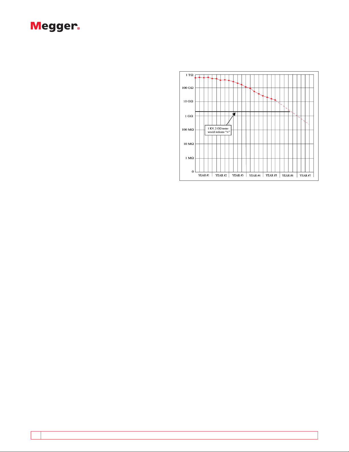
Significant changes in insulation quality can occur at
high levels of insulation resistance, beyond the range
of more limited instruments, as shown by graph in
Figure 15.
In this example, a limited range tester would not
capture this valuable data. We can clearly see that,
although the last recorded insulation value is in excess
of 10 GΩ, the rate of decline is increasing; something is
wrong. An instrument with a range limited to 2000 MΩ
would miss this totally. By the time the readings had
degraded into the instrument’s range, the maintenance
person would be left with comparatively little time to
schedule routine off-line maintenance. (It may even be
too late to rectify the fault condition.)
Figure 15: Changes in Insulation Resistance at High Values
DIAGNOSTIC HIGH VOLTAGE INSULATION TESTS
Diagnostic insulation tests electrically stimulate the
insulation and measure the response. Dependent upon
that response, we can draw some conclusions about the
condition of the insulation.
Diagnostic insulation testing covers a very wide range of
techniques, some of which involve portable equipment
and some that require considerable fixed equipment.
Here we shall consider only those tests that may be
performed with a readily portable dc insulation tester.
These are:
n
Trending spot tests
n
Time constant
n
Polarization Index (PI)
n
Step Voltage (SV)
n
Dielectric Discharge (DD)
Each test gives a different view, or window, into the
condition of the insulation; the whole picture is only
available when all required tests have been completed.
Spot Reading Test
The spot reading test is the simplest of all insulation
tests and the one most associated with lower voltage
insulation testers; the test voltage is applied for a short,
specific period of time (typically 60 seconds as usually
any capacitive charging current will have decayed by this
time) and a reading is then taken. The reading can then
14 A GUIDE TO DIAGNOSTIC INSULATION TESTING ABOVE 1 KV
Page 15

be compared to the minimum installation specifications.
Unless the result is catastrophically low, it is best used
when trended against previously obtained values.
However, insulation resistance is highly temperature
dependent, and thus the results should be corrected to a
standard temperature, usually 40º C. While temperature
effects will be covered later, a good rule of thumb is
that for every 10º C increase in temperature, the current
doubles (resistance halves). The key to making the spot
reading test valuable is consistent timekeeping, effective
record keeping, and trending of results.
As noted previously, the increased sensitivity available in
microprocessor-based diagnostic insulation testers allows
the operator to identify insulation problems in their
early stages rather than when those problems become
catastrophic. In many cases, the trend is far more
important than the absolute value.
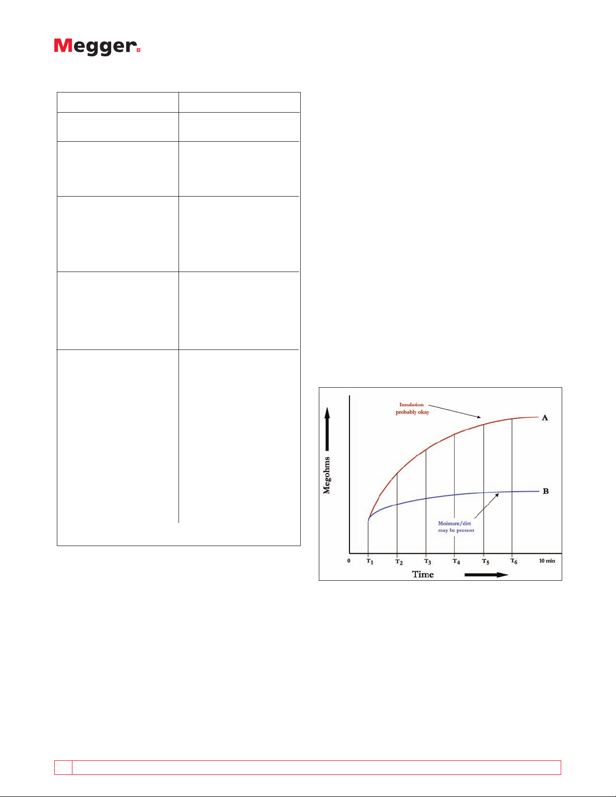
Compare the two traces in Figure 16. Apparatus “A”
shows a high insulation resistance while Apparatus
“B” shows a low value. However, when the trend is
examined, Apparatus “B” shows little cause for concern;
it has been around the same value for several years and
shows every prospect of continuing in the same vein for
many years to come. Conversely, the curve for Apparatus
“A” is diving dramatically and the apparatus will, if
nothing is done to prevent it, fail within the next
few years.
While Apparatus “A” has much higher absolute
resistance values than Apparatus “B,” the trend is quite
worrying. Apparatus “B” has a fairly consistent flat
trend, indicating that the insulation quality is probably
acceptable.
Insulation resistance readings should be considered
relatively rather than absolutely. They can vary widely
for one motor or machine tested three days in a row, yet
not mean bad insulation. As mentioned, the important
information is the trend in readings over a time period,
showing lessening resistance and warning of coming
problems. Periodic testing is, therefore, critical to
preventive maintenance of electrical equipment. The
interval between tests (monthly, twice a year, once
a year, etc.) depends upon the type, location, and
importance of the equipment. Evaluating a series of
readings taken over a number of months or years moves
the operator toward being a diagnostician.
Periodic tests should be made in the same way each
time. Use the same test connections and apply the same
test voltage for the same length of time. Tests should
also be made at about the same temperature, or the
operator must correct them to the same temperature. A
record of the relative humidity near the equipment at
the time of the test is helpful in evaluating the reading
and trend as low temperatures and high humidity might
suggest condensation on the surface of the insulation.
For this reason it is essential to ensure that equipment to
be tested is at a temperature in excess of the dew point,
as otherwise, condensation will form which will distort
the readings unless the measurement is well “guarded.”
The table on the following page contains some general
observations about how to interpret periodic insulation
resistance tests and what should be done with the result.
Figure 16: Comparison of Trended Test Results
A GUIDE TO DIAGNOSTIC INSULATION TESTING ABOVE 1 KV 15
Page 16
Condition What To Do
a) Fair to high values and
n
No cause for concern.
well maintained
b) Fair to high values but
n
Locate and remedy the
showing a constant cause and check the
tendency towards downward trend.
lower values
c) Low but well ww
n
Condition is probably
maintained all right but cause of
low values should be
checked. May simply
be the type of
insulation in use.
d) So low as to be unsafe
n
Clean, dry out, or
otherwise raise the
values before placing
equipment in service
(test wet equipment
while drying out).
e) Fair or high values pre-
n
Make tests at frequent
viously well maintained intervals until the
but showing sudden cause of low values is
lowering located and remedied
or,
n
Until the values have
become steady at a
lower level but safe for
operation or,
n
Until values become so
low that it is unsafe to
keep the equipment in
operation.
large, constant current. The net result is that with
“good” insulation, leakage current is relatively small
and resistance rises continually as current decreases
from the effects of charging and dielectric absorption.
Deteriorated insulation will pass relatively large amounts
of leakage current at a constant rate for the applied
voltage, which will tend to mask the charging and
absorption effects.
Graphing the resistance reading at time intervals from
initiation of the test yields a smooth rising curve for
“good” insulation, but a “flat” graph for deteriorated
equipment. The concept of the time resistance test is to
take successive readings at specified times. It is based
on the relative magnitudes of leakage and absorption
currents in clean, dry insulation compared to that of
moist or contaminated insulation. Good insulation
shows a continual increase in resistance over time. With
contaminated insulation, the leakage current is much
larger and the effects of the absorption current are,
therefore, much less apparent.
The benefits of the time resistance test are that it is
relatively independent of temperature and can give
conclusive information without the records of past tests.
Time vs. Resistance Test
Familiar, standardized test procedures that have
been employed for years benefit from the improved
capabilities of enhanced diagnostic testing. Most basic of
these is the time-resistance method. A valuable property
of insulation, but one that must be understood, is that
it “charges” during the course of a test thanks to the
movement of electrons as explained previously. This
movement of electrons constitutes a current.
Its value as a diagnostic indicator is based on two
opposing factors; the current dies away as the structure
reaches its final orientation, while “leakage” promoted
by moisture or deterioration passes a comparatively
16 A GUIDE TO DIAGNOSTIC INSULATION TESTING ABOVE 1 KV
Figure 17: Time Resistance Test Graph
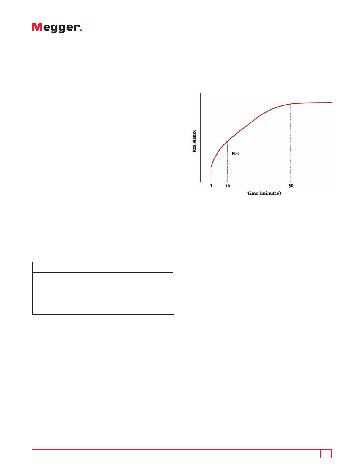
Polarization Index Test
The simplest implementation of the time resistance
test for solid insulation is represented by the popular
Polarization Index (PI) test, which requires only two
readings followed by a simple division; the one-minute
reading is divided into the ten-minute reading to
provide a ratio. The result is a pure number and can
normally be considered independent of temperature
Page 17
since the thermal mass of the equipment being tested
is usually so great that the overall cooling which takes
place during the 10 minutes of the test is negligible.
In general, a low ratio indicates little change, hence poor
insulation, while a high ratio indicates the opposite.
References to typical PI values are common in the
literature, which makes this test very easy and readily
employed. However, we say “in general” because as
mentioned previously there are materials that exhibit
very little or no dielectric absorption. Carrying out a test
on these materials would then produce a result very
close to 1.
Note that resistance readings alone are difficult to work
with, as they may range from enormous values in new
equipment down to a few megohms just before removal
from service.
A test like the PI is particularly useful because it can be
performed on even the largest equipment, and yields
a self-contained evaluation based on relative readings
rather than absolute values. But no PI can be calculated
with a tester of limited range, because “infinity” is not
a number! Advanced testers reach the teraohm range,
and therefore, do not run off the graph. The largest and
newest capital equipment can be readily tested to yield
repeatable data for recording and subsequent trend
evaluation. The following chart highlights selected PI
values and what they mean to the operator.
Polarization Index Insulation Condition
<1 Poor
operator would have to wait until the reading stabilized.
For this reason it is normal to conduct a PI test at
relatively low voltage before applying the high voltages
typically applied for a withstand test.
Figure 18: Benefit of the Polarization Test for Large Equipment
Although the PI value table has been used for many
years and is well accepted, PI readings can occasionally
be encountered which are exceptional. Many years ago
the freshly cooked stator of a 3750 kVA generator was
tested and a PI of 13.4 was obtained. The stator had
cooled down and no doubt was still in its curing phase.
Subsequent tests yielded reducing PI values until it
stabilized around 4.7. During routine maintenance, PI
values do not reach these heady heights.
1-2 Questionable
2-4 Okay
>4 Good
It is also interesting to note that many people have tried
to use the PI test on oil-filled transformers and cannot
understand why a known good transformer gives them
results close to 1. The answer is simple. PI testing is not
appropriate for oil-filled transformers. The concept
Values above 4 indicate excellent equipment for
which no action is likely to be necessary within the
immediate maintenance schedule. The operator may
be called upon to make critical judgments, however.
Some high values of PI (above 5) could indicate brittle
or cracked insulation; this should be fairly obvious. A
sudden increase in PI greater than 20%, without any
maintenance having been performed, should serve as a
warning; insulation may hold its value for long periods,
but is not likely to dramatically improve all by itself.
A benefit of the PI test is that it can provide an
indication of insulation quality in ten minutes on very
large pieces of equipment that might take an hour
or more to fully charge. With a spot reading test, the
A GUIDE TO DIAGNOSTIC INSULATION TESTING ABOVE 1 KV 17
depends on the relatively rigid structures of solid
insulating materials, where absorption energy is required
to reconfigure the electronic structure of comparatively
fixed molecules against the applied voltage field.
Because this process can go to a theoretical state of
completion (at “infinite time,” which obviously cannot
be achieved in the practical field, but can be reasonably
approximated), the result is a steady diminution of
current as molecules reach their “final” alignment.
Because the PI test is defined by this phenomenon, it
cannot be successfully applied to fluid materials since
the passage of test current through an oil-filled sample
creates convection currents that continually swirl the oil,
resulting in a chaotic lack of structure that opposes the
basic premise upon which the PI test rests.
Page 18
Step Voltage Test
Since good insulation is resistive, an increase in test
voltage will lead to an increase in current with a result
that the resistance remains constant. Any deviation
from this could signify defective insulation. At lower
test voltages, say 500 V or 1000 V, it is quite possible
that these defects might be unobserved, but as the
voltage rises we reach a point where ionization can take
place within cracks or cavities, resulting in an increase
in current, and therefore a reduction in the insulation
resistance. Note that it is not necessary to reach the
design voltage for the insulation for these defects
to become apparent, since we are simply looking for
ionization in the defect.
The Step Voltage test follows exactly this principle and
can be employed usefully at voltages reaching 2500 V
and upwards. The Step Voltage test may be employed
as an undervoltage or overvoltage test. However, it
must be remembered that an overvoltage test can lead
to a catastrophic failure if the insulation breaks down
because high voltage test sets have a lot of power
available. An undervoltage test carried out by an
insulation tester has relatively little power available and
it is therefore far less likely to result in a destructive test.
may be further revealed by breakdown or arcing.
A “stuttering” or “jittery” pointer movement can
anticipate this condition as the breakdown voltage is
neared. It may be desirable to terminate the test at such
point before insulation breakdown further deteriorates
the condition of the test item.
Figure 19: Step Voltage Step Graph
A recognized standard procedure is to increase voltage
in five equal steps at one-minute increments and
record the final insulation resistance at each level. Any
marked or unusual resistance reduction is an indication
of incipient weakness. Modern electronics allows these
readings to be captured automatically.
Following are some possible results from a Step Voltage
test on a motor from 500 to 2500 volts and what they
mean to the operator:
n
No appreciable difference in values - Insulation is in
reliable condition.
n
Appreciable difference in values - Insulation requires
more thorough reconditioning.
n
Insulation fails at 2,500 V - Motor is in question;
would most likely fail in service even if an attempt
were made to recondition it on the basis of lowvoltage tests only.
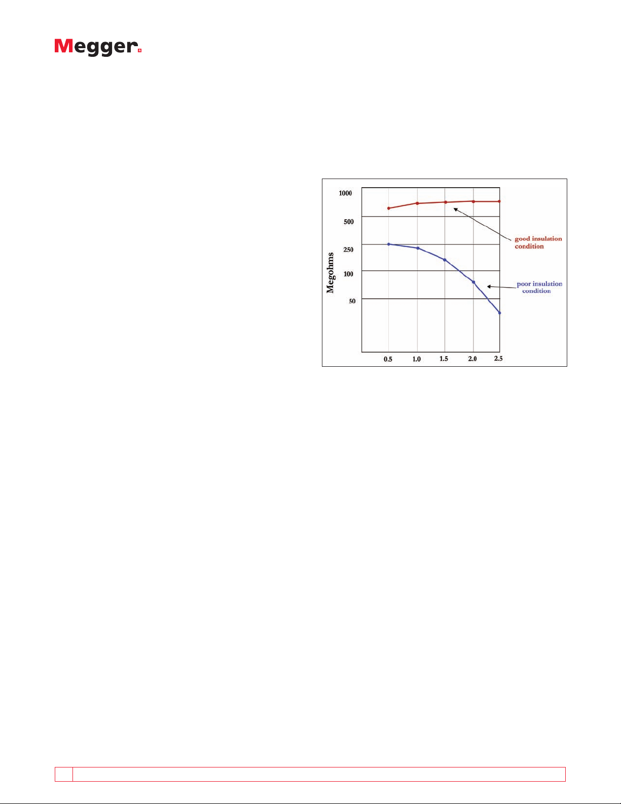
The graphs in Figure 19 are taken from a motor that
was damp and dirty (lower trace) and after cleaning and
drying (upper trace).
In general, if a deviation of 25% in resistance
measurements is observed over the range of successive
voltages, it is an indication of the presence of moisture
or other contamination. Localized physical damage
Like the PI test, the Step Voltage test is a repeatable,
self-evaluating test that, because of its short duration, is
free of extraneous influences like temperature effect.
Dielectric Discharge Test
The Dielectric Discharge test (DD) is a relatively new test
method that was developed by EdF, the national power
utility of France, and based on years of research. While
the other methods mentioned measure the currents
flowing during the charging process, the DD test
measures the current that flows during discharge of the
test sample. As such, it is not a pure insulation resistance
test but rather an adjunct to traditional insulation tests.
The charge that is stored during an insulation test is
automatically discharged at the end of the test when
the insulation tester’s discharge resistors are switched
across the terminals.
18 A GUIDE TO DIAGNOSTIC INSULATION TESTING ABOVE 1 KV
Page 19

be viewed independently of the “masking” currents that
are dominant during the charging phase of an insulation
test.
The measured results are then entered into the following
formula and an index is calculated.
Current flowing after 1 minute (nA)
Test Voltage (V) x Capacitance (µF)
The measurement is temperature dependent, so it is
important to test at a reference temperature or to record
the temperature.
Figure 20: Discharge of Test Item’s Stored Charge
The rate of discharge depends only on the discharge
resistors and the amount of stored charge from the
insulation. However, the capacitive charge is discharged
rapidly until the voltage across the insulation has
reduced to almost zero. At that time, the effect of
leakage currents will be negligible. So only the reversal
of dielectric absorption is left. This is known as dielectric
reabsorption and is a mirror image of the dielectric
absorption.
The capacitive current quickly decays from a high value
with a relatively short time constant (a few seconds). The
absorption (or reabsorption during a discharge) current
always starts at a high level but has a much longer time
constant (up to many minutes). It is caused by the dipoles
randomizing their alignment within the insulation and
the electron shell returning to an undistorted shape.
This has the effect of a current flowing if the discharge
circuit is still connected, or a voltage reappearing on
the sample if it is left open circuit. Rapidly removing the
effects of leakage and capacitive currents allows the
possibility of interpreting the degree of polarization
of the insulation and relating it to moisture and other
polarization effects.
Insulation in high voltage equipment often consists of
layers, each having its own capacitance and associated
leakage resistance. When insulation is built up in this
way, the aim is to make each layer such that the voltage
stress is shared equally between layers. When the
insulator is discharged, each layer’s charge will decrease
equally until there is no voltage remaining.
When a layer is faulty between good layers, its leakage
resistance will decrease while capacitance is likely to
remain the same. A standard insulation test will be
determined by the good layers, and not likely to reveal
this condition. But during dielectric discharge, the time
constant of the faulty layer will mismatch the others to
yield a higher DD value. A low DD value indicates that
reabsorption current is decaying quickly, and the time
constant of each layer is similar. A high value indicates
that reabsorption exhibits long relaxation times, which
may point to a problem.
The test item is first charged for anywhere from 10 to 30
minutes at high voltage until full absorption has taken
place. (The Megger insulation testers that automate this
test charge the test sample for 30 minutes.) At this time,
capacitance is fully charged and the dielectric absorption
is essentially complete. Only leakage current continues
to flow. At this point the test voltage is removed and
the insulation is discharged through the instrument’s
internal discharge resistors to quickly discharge the
Figure 21: Reabsorption Currents
capacitive charge. After 60 seconds of discharge, any
remaining current flow is measured. At this time, the
capacitance has been discharged and the voltage has
collapsed so that the charge stored in the dipoles can
A GUIDE TO DIAGNOSTIC INSULATION TESTING ABOVE 1 KV 19
Page 20

Typical conditions from practical research, primarily
carried out on generators by EdF, arrived at the
figures of merit in the following table. This technique
was developed for high voltage generators but has
application on any multilayered insulation.
DD Value (in mA V-1F-1) Insulation Condition
> 7 Bad
4 - 7 Poor
2 - 4 Questionable
< 2 OK
Different Problems/Different Tests
As we have just seen, the Dielectric Discharge Test can be
used to identify problems in a single layer of multilayer
insulation. Other test methods might not point to
problems on this specific type of insulating structure.
Similarly, the Polarization Index test is particularly
valuable in revealing moisture ingress, oil soaks,
and similar pervasive contamination. These invading
contaminants provide convenient paths for electrical
leakage, which damages the surrounding insulation
and eventually burns through as a “short.” This type of
problem is revealed at almost any test voltage and will
appear as a characteristically “flat” PI. Moisture and
contaminants will also bring down the readings, but this
requires a previous value for comparison; the PI test has
the advantage of making an internal comparison.
However, other problems may seem to “pass” a PI or
simple Spot Reading test by yielding high resistance
values at a given voltage. Such problems include
localized physical damage like pinholes or dry, brittle
insulation in aged equipment. Step voltage tests reveal
such problems. Increasing numbers of imperfections will
pass current as higher and higher voltage is applied, and
be reflected in a declining resistance. Higher voltage
will pull arcs across small air gaps, thereby providing an
“early warning” of an incipient problem. As equipment
ages, such gaps can narrow by accumulation of dirt and
moisture until a short to ground develops.
20 A GUIDE TO DIAGNOSTIC INSULATION TESTING ABOVE 1 KV
Page 21

APPENDICES
Potential Sources of Error/Ensuring Quality Test Results
The following section identifies several areas of
potential error in insulation testing above 1 kV. These
factors may be of less importance in 1 kV testing, but
increased voltages and sensitivities make them critical
for higher voltage testing.
Test Leads
Beware of instruments with low quality leads whose
voltage rating is less than the test voltages employed.
It is extremely important that the only leakage currents
during a measurement are those that are developed
by the insulation under test. If the leads themselves
produce leakage, you may be measuring lead insulation
resistance rather than the item under test.
All leads supplied with Megger insulation testers are
high quality leads, which have been tested to withstand
voltages well above the highest test voltage generated
by the particular instrument. Even then, it is important
to reduce stray leakage by preventing the leads from
contacting each other, the ground and particularly
water.
Making Measurements above 100 GΩ
Measurements up to 100 GΩ can be made without
any special precautions, assuming that the leads are
reasonably clean and dry. The guard can be used to
remove the effects of surface leakage if necessary.
Greater precautions are required when measuring
resistances above 100 GΩ as stray leakage current can
spoil the quality of the readings taken. Be aware of the
following:
n
Test leads should not be allowed to touch each
other or any other object since this will induce
leakage paths.
n
Sharp points at the test lead connections should be
avoided since this will encourage corona discharge.
n
Instrument test jacks should be deep so that
unwanted leakage does not occur between the
terminals.
Accuracy Statements
Pay close attention to an insulation tester’s accuracy
statement. Do not accept a mere plus/minus percentage
for digital units. The statement must also include plus/
minus a number of digits, as no digital display can fix
its last digit (least significant digit, or l.s.d.) to a single
number. Accuracies specified as “percent of reading”
indicate the same error at all points on the scale.
Analog statements listed as “percent of scale” or “full
scale deflection” (f.s.d.) can be deceptive. Because
the accuracy interval is based on the full-scale length,
it translates into an increasing percentage error as
the readings rise against a logarithmic scale. In other
words, the same number of pointer widths on the
expanded low end of the scale will account for only a
few megohms, while on the contracted upper end, this
will be hundreds of megohms. Therefore, when meeting
a desired or required accuracy spec, don’t stop at the
percentage statement but also examine the terms.
Delivery of Stated Voltage
Voltage regulation is indicated for an insulation tester
with a load graph in the instruction manual showing
the output voltage against resistance load. The load
curve ensures that, at typical insulation resistance values,
the insulation tester is delivering full rated test voltage
to the test item. While this may appear to be obvious,
it is not necessarily the case unless so stated by the
manufacturer of a given tester. A poorly-regulated tester
may load down under a high-resistance load so that the
insulation of the test item may actually be experiencing
only a fraction of the rated test voltage, which the
transformer can output only under maximum conditions.
Such instrumentation is not likely to come provided with
a load curve.
It was this condition that inspectors from specifying
agencies, like UL
®
, discovered among “testers” that
were “jury-rigged” from on-hand transformers and
other components at job sites to perform high potential
tests. The inadequacies of such systems lead to the
highly specific language pertaining to output voltage
that now commonly appears in the standards literature.
Megger insulation testers conform by delivering and
maintaining the rated test voltage once a minimum load
commensurate with typical insulation values (generally 1
to 10 MΩ, depending on model and voltage selection) is
applied. Test voltage is typically a few volts above rated,
but should not drop below it, maintaining the integrity
of the test and the repeatability when performing
scheduled preventive maintenance. If exceptionally
precise reporting data is mandated, some models display
the actual test voltage in addition to the selected
voltage and this information is included among the data
provided at the conclusion.
Interference Rejection
Interference is the electrical noise produced at a
variety of frequencies, which can appear in the sample
being tested. It is usually induced currents or voltages
from adjacent equipment and is very common in
A GUIDE TO DIAGNOSTIC INSULATION TESTING ABOVE 1 KV 21
Page 22

substations, particularly high voltage substations
where power frequencies predominate. This electrical
noise superimposes an ac signal on the dc test current
and can cause considerable variations in readings and
may prevent the operator getting a reading at all if
it is beyond the capabilities of your instrument. As an
example, 4 mA of 50/60 Hz noise is fairly typical of
the electrical noise that can be encountered in large
substations (400+ kV).
Be aware of the capability of the insulation tester being
used to cancel out the effects of this ac noise effectively,
resulting in the ability to make measurements
in increasingly more difficult conditions. Not all
noise is limited to power frequencies, however. To
accommodate other frequencies some top of the range
instruments incorporate further software filters that
can eliminate the effects of this noise. It is important
that the instrument you use is matched to the level of
interference anticipated.
Rules on Testing and Comparing
Comparison of results in order to determine rates of
degradation is key to the whole preventive/predictive
maintenance concept. However, it must be emphasized
that this concept applies to readings taken at discrete
maintenance intervals. Even then, strict standardization
of test procedure and conditions is imperative.
Comparison of “on-the-spot” readings is a whole
different scenario and fraught with potential error.
It is tempting to try to back up tests with additional
readings. You may make some adjustment to the test
item or setup, or someone else may have difficulty
accepting the result and wish to verify it. But an
insulation tester is not like a multimeter! Highvoltage testing behaves very much like the Heisenberg
Uncertainty Principle (you cannot know both the speed
and position of an electron) applied to insulation. That
is to say, the act of measuring affects the item being
measured, so that subsequent readings are not being
taken on precisely the same item.
As has been described, the act of applying an insulation
test polarizes the insulating material. This effectively
changes its electrical configuration and dielectric
properties. Because insulating material is, by design,
a poor conductor, it can take considerable time for
“relaxation,” or the return to random configuration, to
occur. Immediately upon termination of a test, the item
under test is not precisely the same piece of equipment
that it was before the test. An immediate follow-up
test will be affected, sometimes considerably, by the
charge left from the first test. Which measurement is
correct? They both are! They each can be expected
to give a correct measurement of the condition of the
insulation at the time of test. Furthermore, industrystandard discharge procedures are not sufficient for the
institution of a repeat test. Such procedures are aimed
at personnel safety, not qualification of the test item.
Residual charges can remain for hours, or even days,
that may be below human perception yet enormous to a
sensitive meter. Equipment should be left grounded for
several hours, or preferably until the next day, before
additional testing is done. And then, external factors,
especially temperature, must not be overlooked.
This does not mean that on-the-spot retesting should
never be performed. For relative information, it may be
quite valuable. But it must be kept in perspective. Do
not expect the readings to agree.
Two different operators may also not observe the same
degree of detail with respect to procedure. Temperature
is one factor. If the equipment is turned on, perhaps to
check performance, then retested, the second test is not
necessarily comparable to the first. Time of test is also
readily overlooked. One operator may rigidly time the
test while another merely waits for stabilization of the
reading. This can result in measurements being taken
at different points on the time-resistance curve (as has
been illustrated under the “Spot-Reading” test), and
again the two results will not be comparable.
If this seems like excessive attention to detail, consider
the standards agencies. Organizations like UL
®
ASTM
do not write procedures that say, in effect,
®
and
“hook up a meter and take a reading.” Rather, they
specify every variable, including setup, procedure, and
characteristics of the test instrument, before results can
be considered in conformance. Standard maintenance
procedures deserve no less diligence.
CAT Rating
In addition to the obvious performance specifications,
instrumentation should also be evaluated according to
various quality standards. Paramount among these is
safety. One of the most recognized and respected safety
standards has been established by the International
Electrotechnical Commission (IEC) in EN61010-1:2001.
This standard defines the requirements that test
instruments must meet in order to be safe from arc
flash and arc blast in specific environments. It is not
enough to simply determine that an instrument is “CAT
rated”, as it is commonly termed. The CAT rating must
be understood, as it rigorously describes where in the
electrical environment a given piece of equipment can
and cannot be safely employed.
22 A GUIDE TO DIAGNOSTIC INSULATION TESTING ABOVE 1 KV
Page 23

CAT Rating Guidelines
“CAT rating” is rendered in two parameters: one
indicating system level and the other specifying rated
operating voltage. A designation of “CAT IV 600 V”
means that the unit is safe to operate in any electrical
environment up to and including CAT IV, on cable
or apparatus rated up to 600 volts phase to ground.
Beware of products that specify the CAT rating while
failing to list the voltage level. This is incomplete
information and the absence can be costly in terms
of safe operation. The CAT rating defines the level
of transient (spike or surge) that the instrument has
been designed to withstand. Transients vary in size and
duration depending on the source. A transient may
be several kV in amplitude but its duration is notably
short, a typical interval being 50 µsec (microseconds).
Its principle danger is that when it rides on top of
the sinusoidal voltage it can initiate an arc, which
will continue until the end of the cycle. In a CAT IV
environment, the available short circuit current can
exceed 1000 amps. Inside an instrument that happens
to be testing the circuit, this can generate hundreds of
kilowatts of heat in a small space for a few milliseconds.
The rapid expansion of air can cause the instrument
to disintegrate or explode. Fire, burns, and dangerous
flying pieces are the consequence.
Instruments designed to a category rating have
sufficient clearance between critical parts to prevent
an arc from creating the initial breakdown when
a transient occurs. IEC61010 defines the design
requirements in order for instruments to declare a
specific category rating and specifies both the electrical
and physical requirements (called creepage and
clearance distances) that make up the circuitry and
casework.
The Importance of a CAT Rating
CAT rating is determined by distance downstream of
the transformer servicing the premise. The overhead
or underground transmission lines constitute the CAT
IV environment because the energy available from the
supply is much higher near the transformer. This is the
most dangerous environment and requires the highest
degree of protection. As voltage passes through the fuse
panel into the building, the circuit impedance is higher
and transients are damped, reducing the available
energy in the transient. This process of progressive
damping, lower energy and reduced hazard continues
through the remaining categories. Downstream of
the service entrance is the CAT III environment. From
the socket or outlet the rating becomes CAT II, and
inside of equipment (photocopiers, televisions, etc)
isolated by an internal transformer the environment is
CAT I. This attenuation is the reason appliances are not
known to explode, but a multimeter may. The voltage
measurement range on a multimeter may include the
rating for the CAT IV environment, thereby creating an
incorrect impression that the tester can be used there.
Some CAT Rating Basic Statistics
Do not confuse working or steady state voltage with
transient voltages. The tester must be able to safely
withstand transients of several multiples of the rated
voltage. For example, to be rated as safe on a 300 Vrms
phase-to-neutral line in a CAT IV environment, the tester
must be able to withstand an impulse of 4 kV! What is
the actual risk of such occurrences? Small transients of a
few hundred volts occur on most days, but fortunately,
large transients (5 to 10 kV) do not occur often. But that
does not mean that they can be discounted. Working
with a correctly rated instrument, the chances of a
dangerous breakdown are on the order of one in a
million per hour connected to the supply. But reduce
the protection by one category and the chances of an
accident increase by a factor of about 30. This means
that of 100 operators using instruments of the wrong
category on live systems for one hour per day, 200 days
per year, a dangerous situation is likely to occur every 18
months.
Testing Insulation Resistance of Rotating Machinery
In March 2000, the IEEE-SA Standards Board approved
a revision of IEEE Std 43-1974 by the Electric Machinery
Committee of the IEEE Power Engineering Society. This
revision is IEEE Std 43-2000, the “IEEE Recommended
Practice for Testing Insulation Resistance of Rotating
Machinery.” Changes made to the types of insulation
used in electric rotating machines have resulted in
Figure 22: Electrical supply broken down into categories
A GUIDE TO DIAGNOSTIC INSULATION TESTING ABOVE 1 KV 23
Page 24

different insulation resistance characteristics, and
therefore, required a substantial revision to the IEEE
standard. According to the IEEE, the standard is intended
for:
n
Individuals/organizations that manufacture rotating
machines.
n
Individuals/organizations that are responsible for
the acceptance of new rotating machines.
n
Individuals/organizations that test and maintain
rotating machines.
n
Individuals/organizations that operate rotating
machines.
Megger recommends that anyone involved in testing
and/or maintaining rotating machinery review this
standard in detail. We will provide some of the
highlights.
IEEE Std 43-2000 recommends a procedure for measuring
insulation resistance of armature and field windings
in rotating machines rated 1 hp, 750 W or greater and
applies to synchronous machines, induction machines, dc
machines and synchronous condensers. It does not apply
to fractional horsepower machines. It also recommends
the insulation test voltage (based on winding rating) and
minimum acceptable values of insulation resistance for
ac and dc rotating machine windings.
The following chart provides guidelines for the dc
voltage to be applied during an insulation resistance
test. Note that voltages up to 10 kV are recommended
for windings rated at greater than 12 kV.
The standard recommends that each phase be isolated
and tested separately (if feasible) as this approach
allows comparisons to be made between phases. The
two phases not being tested should be grounded to the
same ground as the stator core or rotor body. When all
phases are tested simultaneously, only the insulation to
ground is tested. Insulation resistance measurements
should be made with all external equipment (cables,
capacitors, surge arresters, etc.) disconnected and
grounded as these items may influence the resistance
reading. A common ground should be used to prevent
stray losses in the ground circuit that could effect the
test results.
The standard calls out both the insulation resistance test
and the polarization index test (PI), and recommends
that both tests be made (if possible). It indicates that
testing history should be used to track changes. If history
is not available, the standard provides minimum values
for both tests that can be used to estimate the suitability
of the winding. These are the lowest values at which a
winding is recommended for an overvoltage test or for
operation.
The recommended minimum values for PI are based on
the thermal class of the insulating materials and apply
to all insulating materials regardless of application
per IEC 60085-01: 1984. The PI test is not applicable to
noninsulated field windings. Be aware that a very high
PI (greater than 8) for varnished cambric, shellac micafolium, or asphaltic stator windings may indicate that
the insulation has been thermally aged and may be at
risk of failure. Physical inspection can be used to confirm
if the insulation is dry and brittle.
*Winding Rated Insulation Resistance Test
Voltage (V) Direct Voltage (V)
<1000 500
1000-2500 500-1000
2501-5000 1000-2500
5001-12,000 2500-5000
>12,000 5000-10,000
* Rated line-to-line voltage for three-phase ac machines,
line-to-ground voltage for single-phase machines, and
rated direct voltage for dc machines or field windings
24 A GUIDE TO DIAGNOSTIC INSULATION TESTING ABOVE 1 KV
Thermal Class Rating Minimum PI Value
Class A 1.5
Class B 2.0
Class F 2.0
Class H 2.0
The recommended minimum insulation resistance
after one minute at 40
o
C can be determined from the
following chart. The minimum resistance of one phase
of a three-phase armature winding tested with the
other two grounded should be approximately twice that
of the entire winding. If each phase is tested separately
(with guard circuits being used on the phases not under
test), the observed minimum resistance should be three
times the entire winding.
Page 25

Minimum Insulation
Resistance (MΩ) Test Specimen
kV* + 1 For most windings made before
about 1970, all field windings,
and others not described below.
100 For most dc armature and ac
windings built after about 1970
(form-wound coils).
5 For most machines with random-
wound stator coils and formwound coils rated below 1 kV.
* kV is the rated machine terminal-to-terminal voltage
in rms kV.
The rating of the machine determines whether the
motor windings must achieve the minimum value for
either the insulation resistance test or PI test, or must
achieve the minimum for both tests.
Machine Rating Evaluation Criteria
10,000 kVA or less Should have EITHER a value
of the PI test or a value of the
insulation resistance test
(at 40º C) above the minimum
recommended values.
Above 10,000 kVA Should have BOTH a value of
the PI test or a value of the
insulation resistance test
(at 40º C) above the minimum
recommended values.
Effects of Temperature
Temperature variations can have a significant effect
on insulation resistance readings. Resistance drops
markedly with an increase in temperature for the same
piece of apparatus. Each type of insulating material
has a different degree of resistance change with
temperature. Temperature correction factor tables have
been developed for various types of electrical apparatus
and can be acquired from the manufacturer. Failing
that, it is recommended that you develop your own
correction factor tables by recording two resistance
values for the same piece of equipment at two different
temperatures. A graph may then be plotted of resistance
(on a logarithmic scale) against temperature (on a
linear scale). The graph is a straight line and may be
extrapolated to any temperature so that correction
factors may be read directly.
In lieu of detailed data, the “rule-of-thumb” is that for
every 10º C increase in temperature, halve the resistance;
or for every 10º C decrease in temperature, double the
resistance. For example, a 100 GΩ resistance at 20º C
becomes 25 GΩ at 40º C.
Why is temperature correction important? Consider the
example in the following table of a motor tested at
various times of the year at differing temperatures (all
within a 15º band). The temperature adjustments were
made using the rule-of-thumb correction.
Insulation Temperature Temp. Adjusted
Date Resistance (MΩ) ºF Insulation
Resistance (MΩ)
Jan-01 15,000 68 14,990
Jun-01 9,000 80 14,276
Jan-02 14,500 68 14,490
Jun-02 8,500 82 14,562
Jan-03 14,300 68 14,290
Jun-03 8,700 81 14,341
Jan-04 14,500 68 14,490
Jun-04 8,900 81 14,671
Jan-05 14,200 69 14,748
Jun-05 8,900 80 14,117
Jan-06 13,600 68 13,591
Jun-06 8,900 78 13,071
Jan-07 13,500 66 12,491
Jun-07 7,500 80 11,896
Jan-08 11,300 68 11,292
Jun-08 6,500 80 10,310
Jan-09 8,000 67 7,693
A GUIDE TO DIAGNOSTIC INSULATION TESTING ABOVE 1 KV 25
Page 26

The readings taken create confusion if they are not
corrected for temperature. When plotted, they produce
a chart that is of limited use in determining a trend.
If the same data is corrected for temperature and
plotted, the graph begins to provide a valuable picture
of the deterioration of the insulation.
Temperature correction is particularly important when
testing with higher voltages and at higher levels of
sensitivity.
Effects of Humidity
Humidity (moisture content) has an effect upon
insulation resistance, but it cannot be quantified as
neatly as can temperature effect because different types
of insulation will absorb moisture to varying degrees,
as will varying ages and conditions of the same type.
The best that can be said is that humidity is a factor that
should not be overlooked when evaluating test results.
Unlike temperature, humidity’s effect is not a constant
gradient and as long as the temperature remains above
the dew point, humidity will not appreciably affect
insulation readings.
Increasing humidity in the surrounding (ambient) air
can affect insulation resistance to varying degrees. If
equipment operates regularly above the dew-point
temperature (the temperature at which the moisture
vapor in air condenses as a liquid), the test reading
will not be affected much by the humidity. Even if the
equipment to be tested is idle, the same is true — so
long as its temperature is kept above the dew point (and
the insulation surfaces are free of contaminants, such as
certain lints and acids or salts, which have the property
of absorbing moisture).
Figure 23: Insulation Resistance Graph Not Corrected for
Temperature
Figure 24: Insulation Resistance Graph Corrected for
Temperature
In electrical equipment, we’re concerned primarily with
the conditions on the exposed surfaces where moisture
condenses and affects the overall resistance of the
insulation. Studies show, however, that dew will form
in the cracks and crevices of insulation before it is visibly
evident on the surface. Dew-point measurements will
provide a clue as to whether such invisible conditions
might exist, altering the test results.
Humidity effects require greater attention as test
voltages increase because the higher voltages can
promote ionization much more readily than at low
voltages. As a result, humidity that doesn’t produce a
noticeable effect at 1 kV may produce perplexingly low
readings at 5 kV. This is not necessarily a problem. The
difference in response at two different voltages can be
used to detect moisture and tests carried out guarded
and unguarded can be used to detect surface moisture
or internal moisture.
Ingress Protection
Somewhere in the fine print of most test equipment
product bulletins is an IP rating, a number that gives
the operator vital information. In fact, the IP rating lets
the operator know whether a piece of test equipment is
suited for his/her application and test environment.
26 A GUIDE TO DIAGNOSTIC INSULATION TESTING ABOVE 1 KV
Page 27

“IP” stands for “ingress protection.” That is the degree
to which the instrument can withstand invasion by
foreign matter. The IP rating system has been established
by the IEC (International Electrotechnical Commission),
in their Standard 529, and is used as a guide to help
the operator protect the life of the instrument. It also
can help the operator make a more informed purchase
decision by ensuring that the piece of test equipment
is designed to work in the environment(s) that he/she
faces.
The IP rating is comprised of two digits, each signifying
a separate characteristic. The designation indicates
how well the item is sealed against invasion by foreign
matter, both moisture and dust (the higher the
number(s), the better the degree of protection). What
would a typical rating of IP54 tell a buyer about the
application capabilities of a model? If you want to sound
thoroughly knowledgeable, that’s IP five-four, not fiftyfour. Each digit relates to a separate rating, not to each
other.
The first digit refers to particulate ingress, reflecting
the degree to which solid objects can penetrate the
enclosure. A level of “5” indicates “dust protected” as
well as protected from invasion with a wire down to 1.0
mm. There is only one higher category: “dust tight.” The
second digit refers to moisture. A rating of “4” means
resistance to “splashing water, any direction.” The
higher ratings of 5 through 8 indicate “jetting water”
and “temporary” or “continuous” immersion.
So what? Well, suppose an instrument under
consideration was rated only to IP43. What would
that tell the operator about its usability? Could it be
thoroughly utilized in a quarry or cement plant? Hardly!
The particulate rating 4 indicates “objects equal or
greater than 1 mm.” That’s a boulder in comparison to
particles typically produced by industrial processes. Flying
dust could put the unit out of commission.
Suppose the unit is rated at IP42. A moisture rating of
2 indicates dripping water. Therefore, it would not be
resistant to flying spray. Acquiring an instrument for an
environment that exceeds its IP capabilities likely means
that the operator will need another very soon. What
about a rating of IP40? A moisture rating of 0 means
that the unit is not protected against any liquid ingress.
The following charts provide a guide to various IP ratings
and what they mean to the operator:
Protection Against Access to Hazardous Parts
(First Digit)
Number Description
0 Non-protected
1 Protected against access with back of hand
(50 mm)
2 Protected against access with jointed finger
(12 x 80 mm)
3 Protected against access with a tool
(2.5 mm)
4, 5, 6 Protected against access with a wire
(1.0 mm)
Protection Against Ingress of Solid Foreign Objects
(First Digit)
Number Description
0 Non-protected
1 Objects equal or greater than 50 mm
2 Objects equal or greater than 12.5 mm
3 Objects equal or greater than 2.5 mm
4 Objects equal or greater than 1 mm
5 Dust protected
6 Dust tight
Protection against Ingress of Liquids (Second Digit)
Number Description
0 Non-protected
1 Water dripping vertically
2 Water dripping, enclosure tilted up to 15°
3 Spraying water, up to 60° angle from vertical
4 Splashing water, any direction
5 Jetting water, any direction
6 Powerful jetting water, any direction
7 Temporary immersion in water
8 Continuous immersion in water
A GUIDE TO DIAGNOSTIC INSULATION TESTING ABOVE 1 KV 27
Page 28

High Potential Testing
There is no truly singular definition of the “high
potential” test. It is commonly used, but its definition is
situational, in the “eye of the beholder” it might be said.
Basically, a high potential test is an electrical stress test
conducted at a voltage two or more times rated voltage
and sometimes known as a Withstand or Proof Test.
Since the test is conducted at a voltage considerably
higher than the rated voltage of the equipment being
tested, it is known as an overvoltage test unlike the high
voltage insulation test, which is generally applied at a
voltage below the rated voltage of the equipment. The
act of overvoltage testing creates abnormal stresses in
the test sample and can contribute to the acceleration
of aging in insulation. Indeed, some standards require
the voltage to be increased until the test sample breaks
down.
If an overvoltage test is to be applied, it is normal
practice to apply an undervoltage PI test beforehand to
pre-qualify the insulation.
High potential tests may be carried out with ac or dc
voltages, as appropriate. Samples with considerable
capacitance will appear as a short circuit to an ac test
requiring a test set with very large power capabilities to
overcome the capacitive charging currents. In situations
such as this, it is quite normal to apply a dc test with the
equivalent peak.
Current (nA) Readings vs. Resistance (MΩ) Readings
Insulation testers measure current and then convert it
into a resistance reading. Why do we do this? Well,
predominantly, it’s tradition. Good insulation produces
a high reading while poor insulation produces a
low reading. Also, good insulation is predominantly
resistive. If we double the test voltage, we double the
current flowing but the resistance remains constant.
However, sometimes it is easier to diagnose problems by
considering the actual currents that flow.
The choice is yours because many modern insulation
testers are capable of presenting their measurements in
either unit.
Burn Capability
Full-function insulation testers above 1 kV often include
a “burn” mode. It is a feature that may never be used;
yet it does have a viable function within a narrow range
of application.
Insulation testers will generate high voltages into
significant resistances. However, if a breakdown occurs
within the insulation, the resistance drops, the current
increases, and the voltage drops. If left to its own devices
this would cause the breakdown arc to extinguish, the
resistance to increase, and the voltage to increase which
in turn causes breakdown and so on. This continuing
cycle does not allow the measurement of resistance
and indeed could open pinholes or enlarge burn tracks.
Rather than cause further damage, most insulation
testers will shut down.
However, if you want to find the location of the
breakdown this may be extremely inconvenient. For this
reason some instruments offer an operator selectable
“burn” mode; the automatic shutdown is overridden and
a low current arc is maintained. It must be understood,
however, that the instrument’s short circuit limitation
is still in effect. The tester will not provide a “dead”
short. The function enables the operator to localize or
identify the fault by looking for a spark or wisp of smoke
or perhaps by use of an ionization detector. Pinholes
in windings can be identified, covered with insulating
varnish, and the equipment returned to service. In cable
maintenance, a high potential tester with much higher
currents than insulation testers is used to “break down”
a high-resistance fault, converting it to an “open”
that is much more easily recognized by arc reflection
techniques.
Drying Out Electrical Equipment
Electricity and water do not form a happy partnership
and so it is often necessary to “dry out” insulation. This
may be done to remove surface moisture or perhaps
to drive moisture from the internals of the insulation.
Indeed some pieces of equipment have in-built heater
coils which can be used for this purpose. However,
several other methods are also available for drying
electrical equipment.
28 A GUIDE TO DIAGNOSTIC INSULATION TESTING ABOVE 1 KV
Page 29

The most satisfactory solution to the problem
involves placing the windings in an oven with suitable
temperature control and proper air circulation. Banks
of infrared lamps may be used when this is not possible,
or a suitable housing may be built around the machine,
using steam coils or electric resistance type units for a
source of heat. Openings must be provided for the free
circulation of air as otherwise the expulsion of moisture
would simply result in an increasing humidity inside the
drying chamber. Blowers may be used to increase the air
movement.
Vacuum drying has been also effectively used to expedite
the return of equipment to service, but this method
requires extra precautions and should only be undertaken
by experienced personnel.
Another method often used is to circulate low-voltage
current through the windings. This method should not be
used, however, until the insulation resistance has reached
a value of at least 100 MΩ. The current should be limited
to only a fraction of nameplate amperes, and a careful
check must be maintained on maximum temperatures on
the insulated parts. Maximum drying temperatures on
windings should not exceed 194º F
(90º C) as measured by a thermometer. This will prevent
not only the rapid thermal deterioration of the insulation
but damage from the high vapor pressures that would be
obtained if steam were produced.
If drying is required, records help determine when
the insulation is moisture free. As an example of the
importance of past readings, consider a motor that’s been
flooded. After a cleanup, a spot reading with the Megger
tester shows 15 MΩ. If past records showed the insulation
resistance to run from 10 to 20 MΩ, the motor would be
in good shape. If, on the other hand, past records showed
the normal resistance values to run from 100 to 150 MΩ,
the operator would know that moisture was still present
in the motor windings.
During drying operations, when insulation resistance
values are used as an indicator of the suitability of
windings for service or for application of test potential,
the drying must be continued for a sufficient time
to make sure that the values are reliable. Often the
resistance curve will take one or more sharp dips before
leveling off or continuing to increase in a positive
direction. This is due to moisture working out of the
windings. When the machine is completely dried out,
further work is required to remove any remaining dust.
This may be done through the use of dry compressed air
at pressure not exceeding 40 psi.
Figure 25: Typical Drying-out Resistance Graph
Figure 25 shows a typical drying-out curve for a dc
motor armature, which shows how insulation resistance
changes. During the first part of the run, the resistance
decreases because of the higher temperature. Then
it rises at a constant temperature as drying proceeds.
Finally, it rises to a high value, as room temperature
(20° C) is reached.
There is a significant caveat when testing wet insulation
with an insulation tester; wet equipment is susceptible
to voltage breakdown. If windings have absorbed a lot
of moisture even low voltages can puncture insulation.
Therefore, the operator should be very careful before
applying high voltages. More advanced Megger
insulation testers allow the test voltage to be set at
anything from a low of 25 volts to a high of 5000 volts in
25-volt increments.
Test Item Discharge
Perhaps you were taught to discharge a capacitor and
then to store the capacitor with the terminals shorted
together. Did you ever wonder why, since you have
discharged the capacitor and maybe had checked that
there was no voltage across the terminals, you needed to
short the terminals?
The reason is the dielectric absorption current. If the
terminals are left unshorted, the energy stored by
dielectric absorption will slowly release with negative
charge migrating to one terminal and positive charge to
the positive terminal. Over a period of time this charge
A GUIDE TO DIAGNOSTIC INSULATION TESTING ABOVE 1 KV 29
Page 30

can build up to a dangerous level, as high as the original
test voltage, and with a considerable amount of energy
to back it up. This energy can kill.
At the end of an insulation test the test sample
closely resembles a charged capacitor; there remains
a considerable amount of energy stored within the
insulation dielectric.
There is an important “rule of thumb” on charging
and discharging items under test. This rule suggests
that the operator discharge the item under test for five
times as long as it was tested. If the operator performs
a 10-minute PI test, he/she should allow the unit to
discharge for 50 minutes.
A good quality instrument will automatically discharge
the test sample as soon as a test is completed or
interrupted. Some lower quality instruments have a
separate discharge selection knob, or switch, which adds
a step to a test. If this step is forgotten, the test item can
be deadly for the next person who handles it.
Megger insulation testers also detect the voltage across
the test sample during the discharge phase and will show
this voltage until it has fallen to a safe level. At this point,
the item is safe to handle.
However, all we have discharged at this point is the
stored capacitive charge. As explained at the start of this
booklet, any capacitance is charged relatively quickly
at the start of a test. Similarly, the capacitive charge is
discharged relatively quickly at the end of a test. But the
dielectric absorption current takes much longer to go in
and also takes much longer to come out.
Thus while the sample is immediately safe to handle, if
the terminals are not shorted they will gradually acquire
charge and become dangerous once again. So, unless
the equipment is going back into service, ensure that the
terminals are shorted and grounded.
Charging Time for Large Equipment
One question we are often asked is, “How long will it
take to charge a particular piece of equipment?” The
answer is, “We don’t know!”
Why not? Well, the answer depends on the actual
configuration of the particular piece of equipment
concerned. For example, the Megger S1-5010 specifies
a charging rate of “less than 5 seconds per microfarad
with 2 mA short circuit current” and “2.5 seconds per
microfarad with 5 mA short circuit current.” Thus, if you
know the capacitance of the test sample you can work
out the charging time; it doesn’t matter if it is a motor, a
cable, or just a slab of insulating material.
Motor Driven Insulation Testers
Another question we are frequently asked is “What
happened to the old wooden box motor driven
insulation testers?” Some people seemed to think that
they set the standard for insulation testing and still do.
These motor driven wooden boxes, with an external
motor, were produced between 1910 and 1972 and used
the original Evershed patented “Cross Coils Ohmmeter.”
This was a large heavy movement that, as the name
suggests, had two coils set at an angle to each other.
This was the first “true ohmmeter.” The construction of
the movement had benefits and drawbacks.
The main benefit was, because of the weight of
the movement, it had considerable inertia and
was, therefore, quite insensitive to interference or
transient events. This resulted in a very smooth motion.
Unfortunately, the sheer weight of the movement made
it fairly delicate and so the instruments needed to be
handled with care. Furthermore, the instruments needed
to be leveled before use and was, therefore, supplied
with a spirit level on the scale and adjustable feet. The
movements were also fairly insensitive with maximum
resistance capabilities that could be measured in high
megohms or low gigohms.
Alternative power sources were developed. The old
generator was big and heavy as anyone who has tried
to hand crank one of these old instruments will attest;
you certainly wouldn’t want to do a PI test while hand
cranking, but if you lacked a mains supply there was no
alternative.
Technology advances meant that “electronic
movements” could be used which were more rugged
and more accurate. New low-voltage generators were
developed which made hand cranking much easier and
then ultimately battery technology enabled pure battery
power to be employed. This resulted in the long term,
very stable power supplies that we see today.
The use of electronics has resulted in lighter, more
rugged, more accurate instruments that respond more
quickly. They can provide more information, which
results in us seeing transient events that were previously
totally hidden by the relative instability of the power
supply and the inertia of the movement.
Which is better? The decision is yours.
30 A GUIDE TO DIAGNOSTIC INSULATION TESTING ABOVE 1 KV
Page 31

MEGGER INSULATION TESTERS
Megger offers a wide selection of 5 and 10-kV testers
to fit your needs. Megger insulation testers give the
electrician, maintenance engineer and repair technician
flexibility and versatility to meet the demands of high
voltage applications.
Models MJ15 and BM15
5-kV Insulation Testers
n
Pass/fail overlays for rapid go/no go testing
n
Insulation resistance to 20 GΩ
n
Voltage range to 600 V indicates auto discharge
MIT510/2 and MIT520/2
5-kV Insulation Testers
n
Line supply or battery operated
n
Measures to 15 TΩ
n
CAT IV 600 V rating
n
Digital/analog backlit display
n
Data storage and downloading (RS232 or USB)
capability (MIT520/2)
n
Automatic IR, DAR, PI, SV and DD tests
The MIT510/2 and MIT520/2 provide a high level of
quality testing along with prime safety, convenience and
portability. MIT510/2 offers selectable test voltages at
250, 500, 1000, 2500, and 5000 V. The MIT520/2 increases
the functionality by permitting test voltage to be set in
any 10 V increment from 50 V to 1 kV, then in 25 V steps
all the way to 5 kV.
Test results are displayed on our patented electronic
digital/analog arc, thereby affording the precision of a
digital reading. For faster charging and testing of large
inductive loads the MIT510/2 and 520/2 feature a 3 mA
short circuit current.
MIT510/2
The BM15 and MJ15 are compact 5-kV insulation testers
that are simple to use and provide a quick, accurate
reading of insulation resistance. Both instruments offer
four test voltages (500 V, 1 kV, 2.5 kV, 5 kV), analog
scales, and measurement sensitivity to 20 GΩ.
The BM15 is powered by 8 “AA” or rechargeable
alkaline batteries while the MJ15 includes a hand-crank
generator in addition to battery power.
S1-552/2 and S1-554/2
5-kV Insulation Testers
n
5 mA high charging current for testing large
generators and cables
n
15 TΩ measurement range
n
CAT IV 600 V rating
n
Data storage and downloading (RS232 or USB)
capability
n
Automatic IR, PI, DD, SV and DAR tests
The S1-552/2 and S1-554/2 insulation testers feature five
preprogrammed test voltages (250, 500,1000, 2500
and 5000 V) and measure to 15 TΩ on the digital scale.
They also have the ability to change the voltage setting
in 10 V increments from 50 to 1000 V and in 25 V
increments beyond 1000 V.
S1-552/2
The S1-552/2 is able to take effective readings in high
voltage substations and switchyards with a noise
rejection of 2 mA at 200 kV and above. The S1-554/2
includes an extended noise and interference rejection up
to 4mA.
A GUIDE TO DIAGNOSTIC INSULATION TESTING ABOVE 1 KV 31
Page 32

MIT1020/2
10-kV Insulation Tester
n
Line supply or battery operated
n
Digital/analog backlit display
n
Variable test voltage from 50 V to 10 kV
n
CAT IV 600 V rating
n
Automatic IR, PI, DAR, SV and DD tests
n
Measures to 35 TΩ
The Megger MIT1020/2 10-kV insulation resistance tester
is designed specifically to assist you with the testing and
maintenance of high voltage electrical equipment. The
unit features an expanded test voltage range from 50 V
to 10 kV, in 10 V increments to 1 kV and 25 V increments
above 1 kV. Its 10-kV output allows for full conformity
to IEEE43-2000, the “IEEE Recommended Practice for
Testing Insulation Resistance of Rotating Machinery.”
For faster charging and testing of large inductive loads
the MIT1020/2 features a 3 mA short circuit current.
S1-1052/2 and S1-1054/2
10-kV Insulation Testers
n
5 mA high charging current for testing large
generators and cables
n
35 TΩ measurement range
n
CAT IV 600 V rating
n
Data storage and downloading (RS232 or USB)
capability
n
Automatic DAR, PI, SV and DD tests
The S1-1052/2 offers a 10,000 V range and the ability
to measure 35 TΩ on the digital scale. The unit also
conforms to the IEEE Standard 43-2000 “Recommended
Practice for Testing Insulation Resistance of Rotating
Machinery.” The S1-1052/2 is able to take effective
readings in high voltage substations and switchyards
with a noise rejection of 2 mA at 200 kV and above. The
S1-1054/2 features a noise and interference rejection
extended to 4 mA, eliminating the possibility of poor,
unrealiable or unstable readings being made in noisy
400 kV and above substations and switchyards.
32 A GUIDE TO DIAGNOSTIC INSULATION TESTING ABOVE 1 KV
Page 33

NOTES:
Page 34

NOTES:
Page 35

Your “One Stop” Source for all your electrical test equipment needs
n
Battery test Equipment
n
Cable Fault Locating Equipment
n
Circuit Breaker Test Equipment
n
Data Communications Test Equipment
n
Fiber Optic test Equipment
n
Ground Resistance test Equipment
n
Insulation Power Factor (C&DF) Test Equipment
n
Insulation Resistance Test Equipment
n
Line Testing Equipment
n
Low Resistance Ohmmeters
n
Motor & Phase Rotation Test Equipment
n
Multimeters
n
Oil Test Equipment
n
Portable Appliance & Tool Testers
n
Power Quality Instruments
n
Recloser Test Equipment
n
Relay Test Equipment
n
TDR Test Equipment
n
Transformer Test Equipment
n
Watthour Meter Test Equipment
n
STATES
n
Professional Hands-On Technical and Safety
®
Terminal Blocks & Test Switches
Training Programs
Megger is a world leading manufacturer and supplier
of test and measurement instruments used within
the electrical power, building wiring and
telecommunication industries.
With research, engineering and manufacturing
facilities in the USA and UK, combined with sales and
technical support in most countries, Megger is
uniquely placed to meet the needs of its customers
worldwide.
For more information about Megger and its
diversified line of test and measurement instruments:
Call: 1-866-254-0962
Email: vfmarcom@megger.com
Or go to our website: www.megger.com
Page 36

UK
Archcliffe Road, Dover
CT17 9EN England
T (0) 1 304 502101
F (0) 1 304 207342
4271 Bronze Way
UNITED STATES
Dallas, TX 75237-1088 USA
T 1 800 723 2861
T 1 214 333 3201
F 1 214 331 7399
2621 Van Buren Avenue
Norristown, PA 19403
T 1 866 254 0962
ISO STATEMENT
Registered to ISO 9001:2000 Reg no. Q 09250
Registered to ISO 14001 Reg no. EMS 61597
1KV_UG_en_V04
www.megger.com
Megger is a registered trademark
 Loading...