

Page 1

APPLICATION NOTE
5 kV and 10 k Insulation testing
BE ON GUARD FOR EFFECTIVE TESTING
What does a GUARD terminal do?
How does it work?
Why does Megger specify GUARD performance?
Where does this fit in with other instrument specifications?
Testing transformers?
Testing Cables?
Testing bushings on outdoor oil circuit breaker?
What are the real benefits of using the GUARD terminal?
Introduction:
The development of the insulation tester by Evershed &
Vignoles is part of our electrical history. Insulation testers
produced by Megger Instruments in Dover dates back to
before to 1897.
Voltage outputs are now available up to 10 kV to suit all
industrial and commercial applications. On the higher
voltage testers (2.5 – 10 kV), which incorporate very high
insulation ranges, is where the GUARD TERMINAL
becomes a major benefit, when testing various devices
that have long surface leakage areas of insulation.
What does a GUARD terminal do?
During insulation testing we are often so preoccupied with
the resistance of the actual insulator we forget the
resistance path on the outer surface of the insulation
material. However this resistance path is very much a part
of our measurement and can dramatically effect our
measurements. For example if dirt is present on the outer
surface of a bush the surface leakage current can be up to
ten times that flowing through the actual insulation.
The surface leakage is essentially a resistance in parallel
with the true insulation resistance of the material being
tested. By using the guard terminal, performing a so-called
three terminal test, the surface leakage current is ignored.
This may be important when high values of resistance are
expected such as when testing high voltage components
like insulators, bushings and cable. These tend to have
large surface areas that get exposed to contamination
resulting in high surface leakage currents across them.
These include:
Larger diameter cables
Porcelain bushings
Power transformers
H.V. circuit breakers
Such products exhibit long creepage paths across their
insulation by the nature of their size. This will cause the
unwanted surface leakage resistance to introduce errors, and is
the reason the Guard terminal is used to enhance the accuracy
of the measurement.
The total current that flows during an insulation resistance
test is made up of three main components:
1. The charging current, which is charging up the
objects capacitance.
2. An absorption current is the current which is
being drawn into the insulation by the polarising of
the electrons, initially high but drops over time, but
at a slower rate than the charging current
3. The conduction or leakage current which is the
small steady state current which divides into two
parts:
a. The conduction path through the
insulation
b. The current flowing over the surface* of
the insulation.
*Surface leakage is the component of the insulation we do
not want to measure if we just want to measure the
insulation resistance of the material. By using the guard
terminal, which is available on most HV insulation testers,
the surface leakage can be excluded from the measurement.
1
Guard Terminal Application Note
5_kV_and_10_kV_IR_ap_en_v01
Page 2
In applications with lower insulation resistance values
(<100MW), such as in L.V. building wiring applications,
this is not necessary, but with values of insulation above
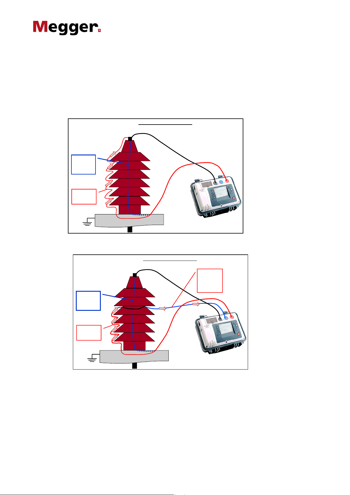
How does it work?
Here we have a typical application for the GUARD
terminal, testing an HV bushing. Without the GUARD
terminal means that the leakage current flowing though
HV BUSHING UNDE R T EST
Leakage
Current
Through
Bushing
Surface
Leakage
Current
the 100MW as found in H.V. insulation applications the use
of the guard terminal is often very important.
the bushing and across the surface is combined and therefore
measured together by the instrument.
Now with the GUARD terminal now in use:
HV BUSHI NG UNDER TEST
Leakage
Current
Through
Bushing
Surface
Leakage
Current
Wire has been wrapped around the bushing and
connected to the GUARD terminal, now the surface
leakage flows to the GUARD terminal. Current flowing
into the GUARD terminal is NOT measured by the
instrument and so is ignored by the insulation resistance
measurement.
Surface
Leakage
Current n ow
not being
measured
To better understand what is actually happening within the
instrument we can look at the following diagram. Put simply
the insulation tester has three main elements; the H.V. d.c.
current source, the H.V. voltmeter and the current meter. The
insulation resistance measurement is simply ohms law,
measured voltage divided by the measured current. The
GUARD terminal allows leakage current to bypass the current
measurement, and so be ignored in the measurement.
Guard Terminal Application Note
2
5_kV_and_10_kV_IR_ap_en_v01
Page 3

INST RUM ENT CIR CUIT SIM P LIFIED
Instrument
Terminal
BUSHING EQ UIVALENT CIRCUI T
Through Bushing Measured
-
0
.
2
CURRENT ME TER – ONLY
MEASURES C URRENT
THROUGH INSULATION
HV DC
CURRENT
SOURCE
Instrument
Terminal
G
Surface
Leakage
Current
Ignored
5
M
o
h
m
0
.
2
5
M
o
h
m
+
Instrument
Terminal
However the story doesn’t end there, as you can see we
have added example values to the above diagram. In this
circumstance any instrument in the Megger MIT or S1
range of insulation testers will provide measurements
with no more than 2% additional error. This is an
important part of the comprehensive specification these
MIT and S1 5 kV and 10 kV range specify the GUARD
terminal performance as:
2% Error guarding 500 kW leakage with 100 MW load
instruments provide.
Why does Megger specify GUARD performance?
To put it simply it is part of the uncertainty of the
measurement. The more leakage current bypassing the
current measurement means less left to measure. This
then becomes a real test of the instruments ability to
accurately measure this remaining test current and
therefore give an accurate measurement of the insulation
resistance.
The Megger specification reassures the user of its ability to
cope under these conditions and provide meaningful results,
and therefore properly diagnose the true condition of the
insulation. Remember effective predictive maintenance relies
on reliable trending of test results to provide early indication
of failure. Time taken to carefully compensate for temperature
variation can easily be wasted by poor results due to surface
leakage not being correctly guarded.
Where does this fit in with other instrument specifications?
Safety?
These days we are more and more recognising the
importance of test instrument safety. Insulation testers
are not an exception. The complete range of Megger
MIT and S1 5 kV and 10 kV insulation testers are
CATIV 600 V to give the user maximum confidence.
So how does this relate to the performance of the GUARD
terminal? Well, to be able to meet the stringent requirement of
CATIV 600 V set out in IEC1010-1: 2001 the instrument has
to be protected against 8 kV high-energy impulses on ALL
terminals. The challenge is to maintain both impulse
protection and the test performance of the instrument.
MAX ERROR 2 %
Leakage Curre nt
100M ohm
3
Guard Terminal Application Note
5_kV_and_10_kV_IR_ap_en_v01
Page 4

Short circuit test current?
The Megger range of MIT and S1 5 kV and 10 kV
insulation testers have at least 3 mA into short circuit
capability. This is not just to allow the instruments to
IEC1010-1:2001
•Protection against input
transients between any terminals
CATIV 600 V
•8 kV transient protected
Challenge is to maintain
protection and GUARD terminal
performance
quickly charge capacitive loads such as long cables. This also
means the instruments have the power to maintain test voltage
across lower resistances.
Insulation value
to be measured
= 600 MW
1.5 MW
1.5 MW
This circuit quickly demonstrates how a 600 MW
insulation resistance can soon present a less than 3 MW
load to the instrument with surface leakage. High power
Surface dirt
causing
leakage =
3 MW
=
=
2.985 MW LOAD
ON INSTRUMENT
maintains the test voltage across the insulation and
provides enough test current to accurately measure the
insulation.
Guard Terminal Application Note
4
5_kV_and_10_kV_IR_ap_en_v01
Page 5

A
Testing transformers?
The two windings both H.V. and L.V. of any particular
phase, in a three phase transformer can be measured with
respect to each other, the guard terminal eliminates the
Leakage
Leakage
current
current
eliminated
ignored
from reading
-
-
Actual
insulation
insulation
resistance
resistance
measurement
required
required
Actual
+
+
surface leakage current flowing over the outside of
contaminated insulators, hence the value of the inter winding
resistance will be read more accurately by the insulation tester.
LV HV
G
G
Transformer winding insulation test with the Guard used ‘ to eliminate leakage current’,
due to the surface path - across dirty porcelain insulators
Here the H.V. winding is measured without the effects of leakage current between the H.V. and L.V. windings using the
guard terminal.
ctual
insulation
resistance
measurement
required
Leakage
current
eliminated
from reading
G
G
LV HV
-
-
+
+
Transformer winding insulation test with the Guard used ‘to eliminate leakage current’,
between windings and across LV bushing
NOTE: In practice both windings on a three phase
transformer are wound concentrically on an insulated
therefore subject to inter-turn or inter-winding breakdown,
and hence the need to insulation test between the two.
former on the same limb of the iron core, they are
5
Guard Terminal Application Note
5_kV_and_10_kV_IR_ap_en_v01
Page 6

Testing Cables?
The guard terminal is also used to remove the effects of surface leakage across exposed insulation at the ends of a cable.
Other conductors connected together and to sheath
Other conductors connected together and to sheath
+
+
-
G
G
BraidLead sheath
BraidLead sheath
Conductor
Conductor
und er test
und er test
-
n the diagram above, the guard terminal is connected to wire wrapped around the exposed insulation to pick up surface
leakage.
In this case a spare conductor in the cable has been used to connect the guard to the exposed insulation at the other end of
the cable.
Lead sheath
Lead sheath
Braid
Braid
Leakage current
Leakage
eliminated from
current
reading
ignored
-
-
+
Leakage current
Leakage
eliminated from
current
reading
ignored
+
G
G
Conductor
Conductor
under test
under test
The guard terminal can also be used to eliminate leakage current between other adjacent conductors in the cable
Leakage
eliminated
from reading
Lead sheath
Lead sheath
Leakage
current
ignored
+
+
G
G
Braid
Braid
Leakage
eliminated
Leakage
from
currents
ignored
reading
-
-
Guard Terminal Application Note
Conductor
Conductor
under test
under test
6
5_kV_and_10_kV_IR_ap_en_v01
Page 7

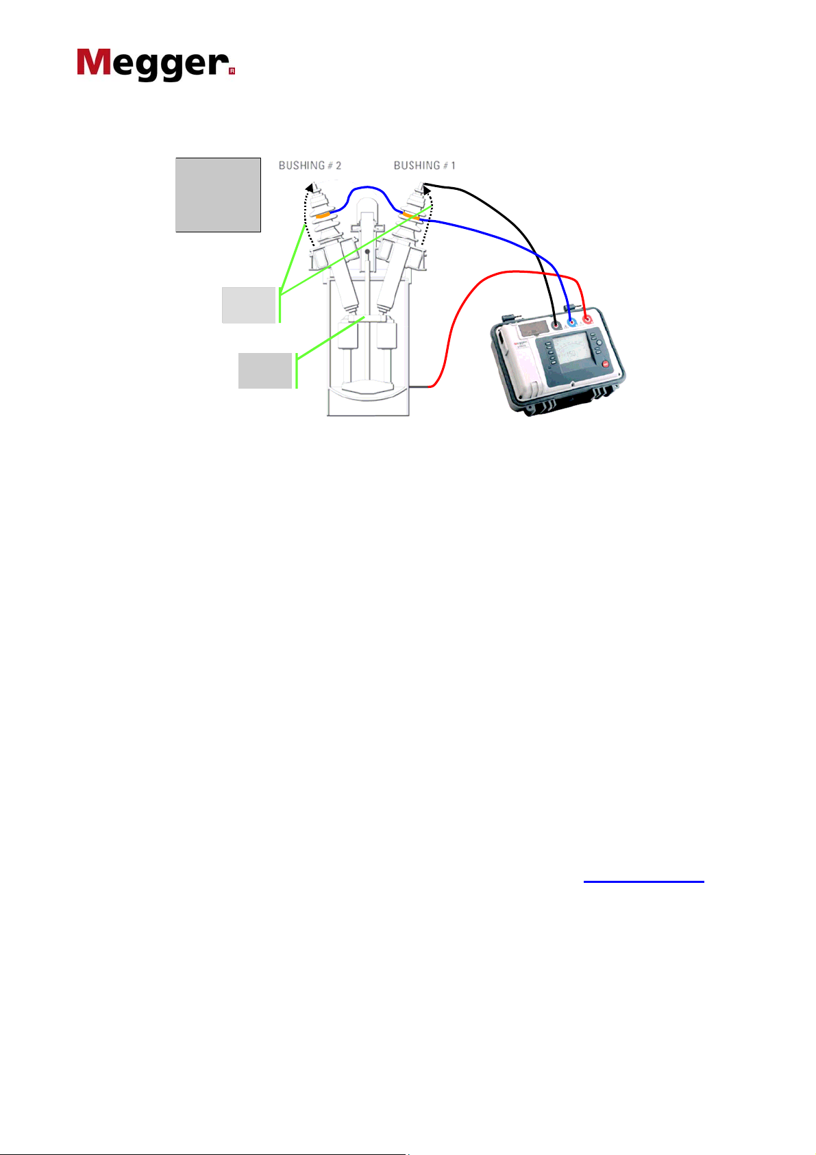
Testing bushings on outdoor oil circuit breaker?
The following four illustrations show the usual methods of testing bushings and associated parts of an outdoor circuit
breaker.
Test 1.
Test 1.
Measuring
Measuring
Bus hing 1
Bus hing 1
Leakage
Leakage
Leakage
eliminated
current
current
from reading
ignored
ignored
Breaker
Breaker
OPEN
OPEN
Test 2.
Test 2.
Measuring
Measuring
Bus hing 1 in
Bus hing 1 in
parallel with
parallel with
cro ss me mb e r
cro ss me mb e r
Leakage
Leakage
Leakage
eliminated
current
current
from reading
ignored
ignored
Breaker
Breaker
OPEN
OPEN
Test 3.
Test 3.
Measuring
Measuring
Bus hing 1 & 2
Bus hing 1 & 2
in parallel
in parallel
Leakage
Leakage
Leakage eliminated
Leakage
current
current
from reading
eliminated
ignored
ignored
from reading
Breaker
Breaker
OPEN
OPEN
Guard Terminal Application Note
7
5_kV_and_10_kV_IR_ap_en_v01
Page 8
Test 4.
Test 4.
Measuring
Measuring
Bus hing 1 & 2
Bus hing 1 & 2
in parallel with
in parallel with
lift rod
lift rod
Leakage
Leakage
Leakage
eliminated
current
current
from reading
ignored
ignored
Breaker
Breaker
CLOSED
CLOSED
What are the real benefits of using the GUARD terminal?
In addition to the big improvements in the reliability of
maintenance discussed above there’s one more big benefit:
insulation condition diagnosis and predictive
The GUARD terminal is an important diagnostic tool!
By performing two tests, one using the GUARD terminal
and one without we can quickly identify when surface
leakage is present and how much. Setting the instrument
to display leakage current makes it easy to subtract the
measurement taken with the GUARD in place from the
There have been many instances of poor insulation resistance
measurements leading to bushes etc. being replaced needlessly
at huge cost. Only to find later, by employing the GUARD
terminal, that they simply needed a good clean!
measurement without. The result tells you exactly how
much current is surface leakage.
Easily identify contaminated surfaces
Don’t throw, use your GUARD and know when to clean
For more detailed information on using the GUARD terminal see the Megger Limited publication ‘A
Stitch in Time’ the complete guide to Electrical Insulation Testing available at www.Megger.com.
Paul Swinerd
Megger Limited
Archcliffe Road
Dover
CT17 9EN
T 01304 502 101
Guard Terminal Application Note
8
5_kV_and_10_kV_IR_ap_en_v01
 Loading...