

Page 1

MFT70-US
Multifunction Tester
With On - board memory
User Manual
Page 2

Contents
Contents
SAFETY WARNINGS 5
Live Ground safety precautions ........................................................................................................................6
Symbols used on the instrument are: ..............................................................................................................7
Introduction 8
Overview .........................................................................................................................................................8
Front panel and controls ..................................................................................................................................8
Display .............................................................................................................................................................8
Display symbols ..............................................................................................................................................9
Waste electrical and electronic equipment......................................................................................................10
Battery and fuse location, fitting and replacement .........................................................................................10
To replace batteries or fuse: ...........................................................................................................................10
For battery replacement: ................................................................................................................................10
For fuse replacement .....................................................................................................................................10
Rechargeable batteries and battery charging ..................................................................................................10
To charge the batteries:..................................................................................................................................11
Operation 12
General operation – all models.......................................................................................................................12
Switching on ...............................................................................................................................................12
Switching off ..............................................................................................................................................12
Backlight .....................................................................................................................................................12
Test buttons .................................................................................................................................................12
Test button lock ..........................................................................................................................................12
Mode button functions ............................................................................................................................13
Test inhibit .....................................................................................................................................................13
Insulation .......................................................................................................................................................13
Continuity ....................................................................................................................................................13
GFCI testing ...................................................................................................................................................13
Ground testing ..............................................................................................................................................13
Battery exhausted ..........................................................................................................................................13
Voltage, frequency, current and temperature measurement............................................................................14
Making a voltage measurement .....................................................................................................................14
OR if using the mains plug lead SAI10:...........................................................................................................14
Frequency measurement ................................................................................................................................15
Phase rotation ................................................................................................................................................15
Leakage current measurement ......................................................................................................................15
Temperature measurement ............................................................................................................................15
Switch probe .................................................................................................................................................15
Continuity / resistance measurement ..............................................................................................................16
Nulling test lead resistance (up to 9.99 ohms) W .........................................................................................16
2
www.megger.com
Page 3

Contents
To null test leads: ........................................................................................................................16
Making a continuity measurement .................................................................................................................17
Storing / downloading results .........................................................................................................................17
Continuity Buzzer ON/OFF..............................................................................................................................17
Switch probe (SP5) .........................................................................................................................................18
Buzzer threshold ............................................................................................................................................18
Measurement methods and sources of error ..................................................................................................18
Method of measurement .............................................................................................................................18
Possible sources of error ...............................................................................................................................18
500
Insulation resistance
Making an insulation measurement ...............................................................................................................19
Insulation test lock .......................................................................................................................................19
Measurement methods and sources of error ..................................................................................................20
Ground Fault Current Interrupt (GFCI) testing ................................................................................................20
V
.............................................................................18
Function button options ....................................................................................................................20
Ramp test ....................................................................................................................................................20
Making a measurement ...............................................................................................................................20
Touch voltage display ...................................................................................................................................21
Measurement methods and sources of error ................................................................................................21
Useful information .......................................................................................................................................22
Ground resistance measurement ....................................................................................................................22
Connection terminals ...................................................................................................................................22
Touch voltage limit .......................................................................................................................................22
Making a measurement - two pole resistance measurement ........................................................................22
Making a measurement – three terminal resistance measurement ...............................................................23
Making a measurement – three terminal resistance measurement using ART ...............................................24
Two-clamp stake-less measurement .............................................................................................................25
Setup options 26
Warning messages .........................................................................................................................................27
Startup warnings ........................................................................................................................................27
Battery .........................................................................................................................................................27
Battery charger ............................................................................................................................................27
Fuse warning ...............................................................................................................................................27
Invalid rotary switch setting .........................................................................................................................27
Continuity test .............................................................................................................................................27
Insulation test ..............................................................................................................................................27
GFCI Test ....................................................................................................................................................27
GFCI range selection errors ..........................................................................................................................27
Test will not start ........................................................................................................................................28
Sending, Storing, Deleting and Recalling Test Results......................................................................................29
www.megger.com
3
Page 4

Contents
Folders: ........................................................................................................................................................29
Circuit type: .................................................................................................................................................29
Insulation: ....................................................................................................................................................29
GFCI: ...........................................................................................................................................................30
Ground testing: ...........................................................................................................................................30
Storing Test Results in the internal memory ....................................................................................................30
Deleting Test Results from the internal memory ............................................................................................30
Recalling Test Results to the display ..............................................................................................................31
Sending stored test results via Bluetooth® ....................................................................................................31
Sending individual (Blobbing) test results......................................................................................................31
Continuity testing ........................................................................................................................................32
GFCI testing .................................................................................................................................................32
Ground testing ...........................................................................................................................................32
Bluetooth® Pairing .........................................................................................................................................33
Bluetooth® Pairing (PC or Laptop) ................................................................................................................33
General Information 34
Installation category definitions ....................................................................................................................34
Safe working practice ..................................................................................................................................34
Cleaning and maintenance ..........................................................................................................................34
Ground resistance testing – Basic principles ....................................................................................................35
Principle of operation (three-terminal resistance measurement) ....................................................................35
Principle of operation (three-terminal resistance measurement using ART) ....................................................35
Principle of operation (two-clamp stake-less resistance measurement) ..........................................................36
General Specification .....................................................................................................................................37
Repair and Warranty ....................................................................................................................................39
CALIBRATION, REPAIR AND SPARE PARTS .....................................................................................................39
Deceleration of Conformity .............................................................................................................................
4
www.megger.com
Page 5

SAFETY WARNINGS
SAFETY WARNINGS
Safety warnings and precautions must be read and understood before the instrument is used.
They must be observed during use.
Warnings:
• The circuit under test must be switched off, de-energised and isolated before test connections are
made when carrying out insulation and continuity tests.
• Continuity of protective conductors and Grounded equipotential bonding of new or modified
installations must be verified before carrying out an Ground fault loop impedance test, GFCI or
Ground testing
• Do not touch circuit connections and exposed metalwork of an installation or equipment under
test. Under fault conditions the system Ground could become hazardous live.
• Do not touch the Ground stakes, test leads and their terminations (including connections to
the Grounding system under test) if an installation Ground fault can arise, unless adequate
precautions are taken.
• The ‘live circuit warning’ and ‘automatic discharge’ functions are additional safety features and
should not be regarded as a substitute for normal safe working practices.
• Do not move the rotary switch positions while a test is in progress.
• Do not operate the instrument or connect it to any external system if it shows any visible signs
of damage or if it has been stored for prolonged periods in unfavourable conditions.
• Do not operate the instrument or connect it to any external system if the battery compartment
or casing is open or any parts of the case (including keypad, selector switch, display window,
etc.) are missing.
• Always disconnect the instrument from all systems while batteries are being changed or the fuse
replaced
• Do not replace rechargeable cells in the instrument with non-rechargeable “dry” cells and
attempt to charge the cells. This can cause explosion or fire.
• Do not operate charging equipment supplied with the instrument in damp or wet environments
or outdoors. All test leads must be removed from the instrument while charging.
• After insulation tests, capacitive circuits must be allowed to discharge before disconnecting
test leads. Locking the insulation test ON should only be used where there is no risk of a circuit
holding a charge.
• The instrument should not be used if any part of it is damaged.
• Test leads, probes and crocodile clips must be in good order, clean and with no broken or cracked
insulation.
• All test leads supplied with the instrument form part of the measuring circuit of the instrument.
They must not be modified or changed in any way, or be used with any other electrical
instrument or appliance.
• A plug severed from the power cord MUST be destroyed, as a plug with bare conductors is
hazardous in a live socket outlet.
• Ensure that hands remain behind guards of probes/clips when testing.
• U.K. Safety Authorities recommend the use of fused test leads when measuring voltage on high
energy systems.
• Replacement fuses must be of the correct type and rating.
• Failure to fit the correctly rated fuse will result in damage to the instrument in the event of an
overload.
• Special precautions are necessary when operating in situations where “live” Grounds may be
encountered: isolation switches and fuses (not supplied with this instrument) must be used.
www.megger.com
5
Page 6

SAFETY WARNINGS
• Special precautions are necessary when working near high tension systems (MV and HV):
rubber gloves and shoes (not supplied with this instrument) should be worn.
• Special precautions are necessary when working in wet conditions or in agricultural
areas: observe the local safety standards and take all necessary special precautions applicable to
the particular location and do not touch the test leads with bare hands.
Live Ground safety precautions
A ‘Live’ ground is one that carries current from the mains supply, or could do so under fault conditions. The
following warnings apply in addition to those listed previously.
Warnings:
• All persons involved must be trained and competent in isolation and safety procedures for the
system to be worked on. They must be clearly instructed not to touch the Ground electrode,
test stakes, test leads, or their terminations if any ‘Live’ Grounds may be encountered. It is
recommended that they wear appropriate rubber gloves, rubber soled shoes, and stand on a
rubber mat.
• The Ground electrode under test should be isolated from the circuit it is protecting before testing
commences. If this is not possible, ART (attached Rod Technique) may be used to measure
electrode resistance.
• The instrument terminals should be connected to the system under test through isolation
switches that are rated to handle the likely maximum fault voltages and currents that could be
encountered at the installation. The isolation switch must be open whilst any personal contact
is made with the remote test stakes, or the connecting leads, e.g. when changing their position.
• The instrument terminals should be connected to the system under test through fuses that are
rated to handle the likely maximum fault voltages and currents that could be encountered at the
installation.
Note: This instrument must only be operated by suitably trained and competent people.
Users of this equipment and/or their employers are reminded that Health and Safety Legislation requires them to
carry out valid risk assessments of all electrical work so as to identify potential sources of electrical danger and risk
of electrical injury such as inadvertent short circuits. Where the assessments show that the risk is significant then
the use of fused test leads constructed in accordance with the HSE guidance not GS38 ‘Electrical Test Equipment
for use by Electricians’ should be used .
This instrument is internally protected against electrical damage when used for the purposes of testing low voltage
electrical installations as defined herein. If used in a manor other than those defined in this user guide, the
protection capabilities could be impaired with potential risk to the operator and the instrument.
6
www.megger.com
Page 7
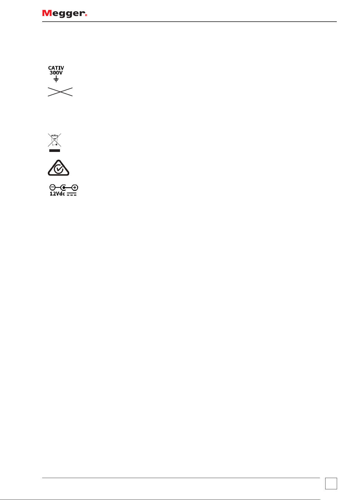
Symbols used on the instrument are:
SAFETY WARNINGS
G
> 600 V
f
c
Caution: Refer to accompanying notes
Maximum 300 V a.c. CAT IV to Ground
Maximum nominal system voltage of 600 V
Instrument protected by 2 x F2 1000 V 30 kA fuses
Equipment complies with current EU Directives
This equipment should be recycled as electronic waste
Equipment complies with ‘C tick’ requirements
12 V DC charger socket
www.megger.com
7
Page 8

Introduction
Introduction
Congratulations on your purchase of a genuine Megger Multifunction tester. The MFT70 series Multi-function tester is a
compact instrument designed to perform all of the functions required by the electrical contractor to fully test domestic,
commercial and industrial wiring. Specially designed to comply with modern US International wiring regulations and
standards, the MFT70 may be used on all single and three phase systems with rated voltages up to 300 V AC rms to
ground.
Overview
Front panel and controls
Display
Test button
Lead Null
Test lock
Setup selector
Results store
Mode
Display
backlight
Display
Primary
functions
Secondary
functions
Touch voltage
contact point
Test button
Lead Null
Test lock
Setup selector
8
www.megger.com
Page 9
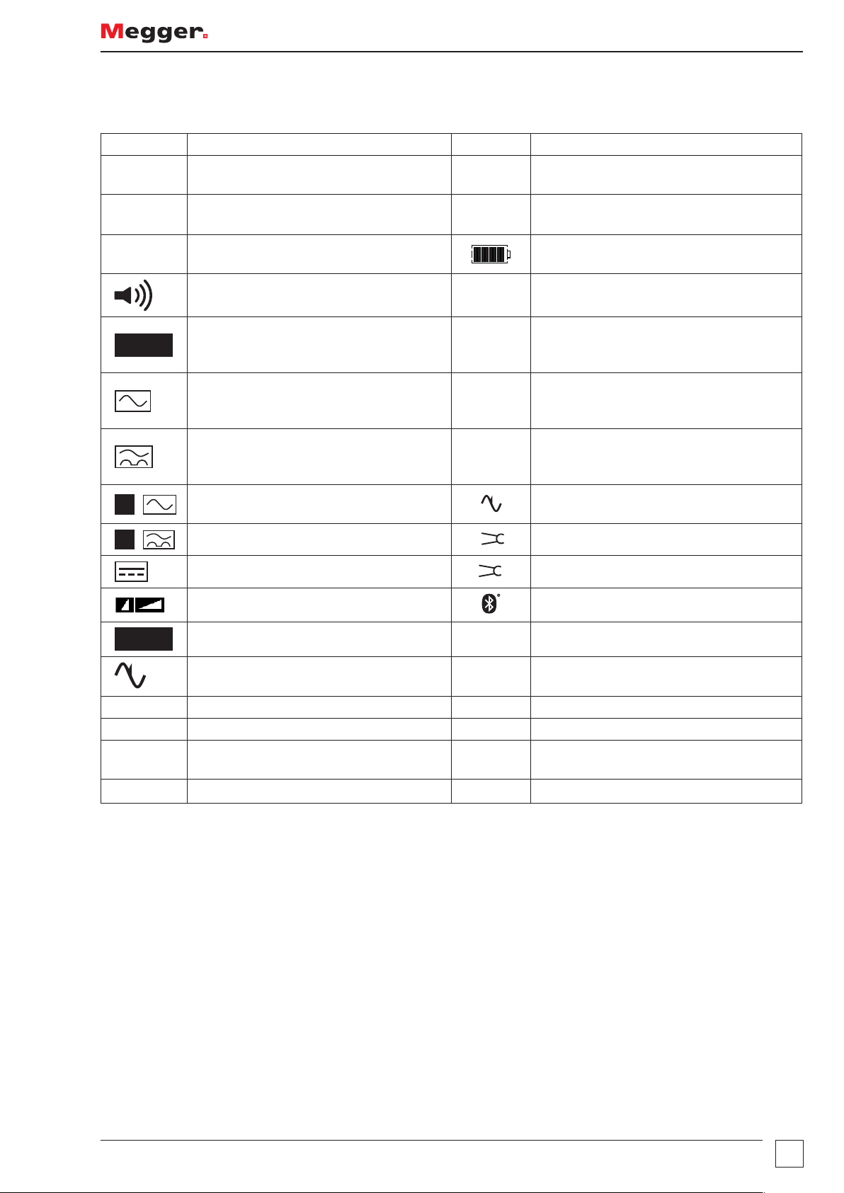
Display symbols
Symbol Meaning Symbol Meaning
l
Test function locked on (also used to
indicate a change is saved in setup)
G
Warning triangle – instruction to refer to
this user guide
Introduction
z
UL = 50V
AUTO
S
S
Test lead null active
Touch voltage limit (and Ground test
voltage) set to 50 V (change setup)
Buzzer enabled NiMH
GFCI test in AUTO mode >100 V
Type AC GFCI selected Rp (Rs)
Type A GFCI selected Rc (RH)
Type S GFCI (Type AC)
Type S GFCI (Type A)
Type B GFCI selected
Fast or Full RAMP test selected Bluetooth® enabled
f
V
V
I
Fuse blown
Battery indicator
Battery type set to rechargeable NiMH Change in “Battery” on page 27
Indicates that the ground noise voltage
exceeds the instrument measurement
capability (test is inhibited)
Potential stake (P stake)
resistance exceeds range for accurate
measurement
Current stake (C Stake)
resistance exceeds range for accurate
measurement
Ground noise voltage exceeds range for
accurate measurement of resistance
Megger Voltage Clamp error
Megger Current Clamp error
TEST
N<->L Live and neutral connections reversed
Zref Reference loop measurement
R1+R2
ZMAX
NOTE: Some features detailed within this user guide are model dependent. Not all features appear on all models.
Instrument is running a test
Ground loop noise detected.
Loop measurement with Zref value
automatically deducted
Loop maximum measurement
T
Instrument is too hot, allow to cool
www.megger.com
9
Page 10
Introduction
Waste electrical and electronic equipment
WEEE
The crossed out wheeled bin placed on Megger products is a reminder not to dispose of the product at the
end of its life with general waste. Follow local regulations.
Megger is registered in the UK as a producer of electrical and electronic equipment. The registration number
is WEE/HE0146QT
Battery and fuse location, fitting and replacement
Battery type: 6 x 1.5 V Alkaline LR6 (AA) or NiMH HR6 rechargeable
Fuse type: 2 x F2 1000 V 30 kA fuses
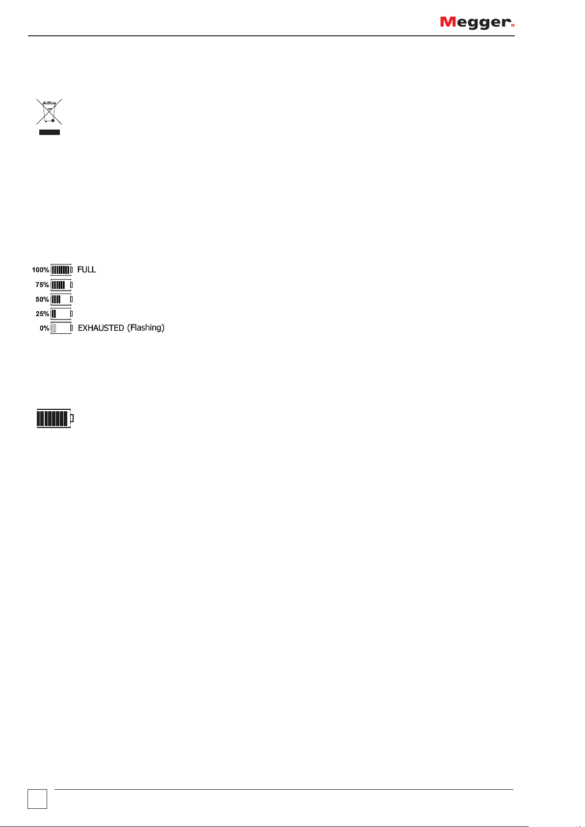
Battery condition is shown by the following display symbols:
Where NiMH rechargeable batteries are fitted, the battery condition display can be adjusted accordingly. Refer to
“Setup options” on page 26 to change between alkaline and rechargeable batteries.
When set to NiMH batteries, the battery indicator in the display will show NiMH under the battery status symbol
as below: (Feature available on all models).
NiMH
To replace batteries or fuse:
Switch off the instrument.
Disconnect the instrument from any electrical circuits.
Remove the battery cover from the base.
For battery replacement:
Remove old cells and refit new batteries following correct polarity as marked on the battery holder.
Replace the battery cover.
Incorrect battery cell polarity can cause electrolyte leakage, resulting in damage to the instrument.
For fuse replacement
Withdraw each fuse in turn and check for failure. The blown fuse must be replaced with a F2 1000 V 30 kA fuse.
Rechargeable batteries and battery charging
Some models are supplied with rechargeable NiMH cells. These batteries can be charged in the instrument, using
the supplied Megger charger.
10
www.megger.com
Page 11

Introduction
To charge the batteries:
Ensure fitted batteries are of the rechargeable NiMH type (as shown above).
Connect the 12 V dc plug of the charger to the socket on the front of the MFT marked
Warning:
• Whenever battery cells are being recharged, there should be no connections to the instrument
terminals and the instrument should be switched off.
• Do not attempt to recharge non-rechargeable (Primary) cells. Doing so may result in instrument
damage and may cause personal injury.
Ensure ambient temperatures are between 4º C and 40º C while charging the MFT.
Note: The crossed out wheeled bin placed on the batteries is a reminder not to dispose of them with general
waste at the end of their life.
Spent Alkaline and NiMH batteries are classified as portable batteries and should be disposed of in accordance
with local regulations.
Megger is registered in the UK as a producer of batteries. The registration number is BPRN00142
www.megger.com
11
Page 12

Operation
Operation
General operation – all models
Switching on
Turn the left hand rotary knob away from the off position.
The instrument will perform internal self tests then display the appropriate test screen, depending on the position
of the function knobs.
Switching off
Turn the primary function (left hand rotary) knob to the OFF position.
The instrument will automatically turn itself off after 20 minutes* of inactivity. Press any button or turn either of
the rotary knobs to turn back on.
* 2 minute option in Setup, refer to “Setup options” on page 26.
Backlight
Press the backlight button. The backlight will operate for 20 seconds.
Test buttons
The test buttons, or , are duplicated on the left and right of the unit. Both buttons perform the same
function except, when the is displayed, in this case the right hand buttons perform a scrolling function. The
left RED button also performs bluetooth, storage and lock functions.
Test button lock
To lock the test button, hold down either of the RED test lock buttons with the L symbol, whilst holding down
the test button. If is displayed, the right hand buttons perform a scrolling function.
12
www.megger.com
Page 13

Mode button functions
The function of the mode button is dependent on the test function selected:
Test selected Function Options Comments
V/º C Volts / mV Temperature requires suitable transducer
Continuity
RLO
Insulation
RSIO
GFCI
Ground (RE) Touch voltage limit 50 V / 25 V Press and release
SETUP
Buzzer
ENABLE/DISABLE
Buzzer
ENABLE/DISABLE
0º / 180º
selection
GFCI Type
Refer to instrument
setup “Setup options”
on page 26.
Buzzer ON
Buzzer OFF
Buzzer ON
Buzzer OFF
0º
180º
AC
A
AC(s)
A(s)
B
Buzzes on <2 Ω
May be changed in SETUP.
Refer to “Setup options” on page 26.
Buzzes on <1 MΩ
May be changed in SETUP.
Refer to “Setup options” on page 26.
(Press and release)
(Press and HOLD)
Operation
Test inhibit
Each test mode has conditions under which testing will be inhibited, as below:
Insulation
Detection of a circuit voltage above 50 V (a warning is displayed at 25 V).
Continuity
Detection of a circuit voltage above that used by the instrument will inhibit testing.
GFCI testing
Touch voltage detected or predicted to exceed 50 V (or 25 V depending on instrument configuration).
Supply voltage over range or under range.
Supply Frequency out of specification.
Ground testing
External voltage greater than 25 V present.
Leads not connected as per the test requirements.
Potential stake not within range (Rp).
Current stake not within range (Rc).
Other conditions that will inhibit testing include:
Battery exhausted
All testing will be inhibited in the event of a flat battery, refer to “Battery and fuse location, fitting and
replacement” on page 10.
www.megger.com
13
Page 14

Operation
Voltage, frequency, current and temperature measurement
Making a voltage measurement
1. Set the Main rotary range knob to volts
(The position of the right hand rotary range knob must not be in the position.)
2. Using two test leads, connect test leads to the L1 (+ve) and L2 (-ve) terminals
L1
L2
L3
N
E
L1
L2
L3
N
E
OR if using the mains plug lead SAI10:
a. For live to neutral measurements, connect the red connector to the L1 terminal and the blue connector to
the L2 terminal
b. For live to ground measurements connect the red test to the L1 terminal and the green connector to the
L2 terminal
L1
N
E
Connection (a) Connection (b)
Note: When connecting all three test leads (eg phase, neutral and ground) or the mains plug test lead, the
voltage displayed is the highest of the three possible voltages.
L1
N
E
Pressing either TEST button scrolls through L-E, N-E and L-N individual voltages. When the frequency of supply is
shown, the voltage displayed reverts to the maximum voltage across all 3 terminals.
Use the Mode button to select mV mode.
14
www.megger.com
Page 15

Operation
L1
L1
Frequency measurement
Automatically displayed when connecting to a live circuit refer to “Making a voltage measurement” on page 14
Phase rotation
Display of Phase rotation is automatic when all three test leads are connected to the 3 phase supply as below:
1. Set the main rotary range knob to volts V
(The position of the right hand rotary range knob must not be in the position.)
2. Using three test leads, connect test leads to the L1 to Phase1, L2 to Phase 2 and L3 to Phase 3. The MFT will
display L1 L2 L3 or L1 L3 L2 depending on the direction of phase rotation.
L2
L3
Normal rotation Reverse rotation
Leakage current measurement
Leakage current measurement uses the optional accessory current clamp (Megger Current Clamp).
1. On the MFT70, set the primary range knob to clamp position .
2. Connect to Megger Current Clamp (part number MCC1010) to the Megger Current Clamp socket on
the MFT.
3. Connect the clamp to the circuit conductor. The MFT will display the (AC) current flowing in the conductor.
Temperature measurement
1. Connect the thermocouple transducer to the L1 (+ve) and L2 (-ve) terminals.
2. Press the Mode button to select º C. (Pressing the mode button will cycle round the V, mV and º C
measurement modes.)
The display will show the temperature at the tip of the temperature probe.
Switch probe
In the V / mV / º C mode all measurements except temperature can be made with the remote switch probe. Tests
are automatic and do not require the test button to be pressed.
Connect the switch probe to the switch probe socket. The probe replaces the standard RED test lead and can
now be used as a normal test probe.
L2
L3
N
E
www.megger.com
15
Page 16

Operation
Continuity / resistance measurement
NOTE: The continuity test will auto-range from 0.01 Ω to 99.9 kΩ. Circuits up to 2 Ω will be tested at >200 mA.
To change the test current refer to “Setup options” on page 26.
NOTE: The continuity test is automatic. Testing starts as soon as the leads are connected to a circuit. The
button is ONLY used to null the lead set.
TEST
Warning:
Prior to any continuity testing, ensure the circuits under test are isolated and not live.
SETUP allows the follow configuration options:
Positive test current
Bi-directional test current
Bi-directional test current allows the automatic testing of the circuit in both directions and the highest measured
value being displayed refer to “Setup options” on page 26.
Nulling test lead resistance (up to 9.99 ohms)
Before starting a continuity test, the test lead resistance should be nulled such that it does not add extra resistance
to the circuit being measured. Once nulled it does not need repeating for each test. Periodically it should be
checked to ensure nothing has changed.
The “Lead Null” value is retained even when the tester is switched off.
W
To null test leads:
Short test probes or clips together and press the
lead null is active.
TEST
button. The null symbol z will be displayed to indicate
Lead null OFF
This null value is stored until the
To cancel the LEAD NULL, separate the test leads and press the
16
TEST
button is pressed again.
TEST
button.
www.megger.com
Page 17

Operation
Making a continuity measurement
1. Set the Primary (Left) range knob to W range. (The position of the right hand rotary range knob must not be
in the position.)
2. Connect two test leads to the L1 (+ve) and L2 (-ve) terminals on the instrument. A continuity measurement is
made automatically.
L
N
E
g
NOTE: Measurements are prevented when:
NOTE: A resistance of > 99.9 kΩ is present
NOTE: Circuit voltages in excess of 4 V are detected.
Storing / downloading results
Once the display shows a value it will automatically be logged into temporary memory. Unless stored, this will be
over written by the next measurement.
To store this result or to send it to a compatible device, refer to “Sending, Storing, Deleting and Recalling Test
Results” on page 29.
Continuity Buzzer ON/OFF
Whilst in the continuity range, press the MODE button . This will toggle the buzzer ON and OFF.
Buzzer ON =
Buzzer OFF = No symbol
www.megger.com
17
Page 18

Operation
Switch probe (SP5)
In CONTINUITY/RESISTANCE mode all measurements can be made with the remote switch probe (SP5). Tests are
automatic and do not require the
Connect the switch probe to the switch probe socket L1 (+ve). The switch probe replaces the standard RED test
lead as in ‘Making a continuity measurement’ above.
TEST
button to be pressed.
Buzzer threshold
If the measured resistance is less than the buzzer threshold, the buzzer will sound. The resistance at which the
buzzer stops sounding can be changed to meet individual test requirements. Refer to “Setup options” on
page 26 of this guide.
Selectable limits of 0.5 Ω, 1 Ω, 2 Ω, 5 Ω, 10 Ω, 20 Ω, 50 Ω, 100 Ω, are available.
This setting is stored even when the instrument is switched off.
Measurement methods and sources of error
Method of measurement
The 2-wire lead set must be used for this measurement. A DC voltage of nominally 4.4 V with a current limit of
>200 mA is used to measure resistance less than 2 Ω.
Possible sources of error
Measurement results can be affected by the following:
The presence of circuits connected in parallel.
Presence of AC voltages on the circuit being measured.
A poor connection to the circuit under test.
Incorrectly nulled test leads.
Use of fused leads.
500
Insulation resistance
NOTE: The insulation test is protected by a live circuit warning. Detection of a voltage over 50 V will inhibit
testing. This applies whether or not the insulation test is locked on.
18
V
www.megger.com
Page 19

Making an insulation measurement
500
1. Set the left hand rotary range knob to the
rotary range knob must not be in the position.)
2. Connect two test leads to the L1 (+ve ) and L2 (-ve) terminals on the instrument.
L1
L2
L3
N
E
V
insulation test voltage required. (The position of the right hand
Operation
3. To start test, press and hold either of the
TEST
buttons, or , on the instrument.
Release the test button after the displayed reading has settled. The circuit will now discharge safely.
Note: A 1000 V warning is displayed whenever the 1000 V range is selected for the first time and the
button is pressed.
Insulation test lock
To lock an insulation test ON, hold down either of the
buttons.
To release the “Locked on” insulation test, press the
Warnings:
TEST
TEST
buttons followed by either of the RED LOCK
button.
TEST
• The test voltage will be permanently present on the test probes or crocodile clips when in the
locked position.
• Auto discharge - Auto discharge facility automatically and safely discharges the circuit at the
completion of an insulation test.
• Live circuit warning - operates when connected to live circuits > 25 V. Testing is still permitted.
• Test inhibited - Live circuits > 50 V will inhibit testing.
www.megger.com
19
Page 20

Operation
L
Measurement methods and sources of error
The selected DC test voltage (current limited to less than 2 mA DC) is applied to the circuit under test and the
resistance is calculated from measurements of the resulting voltage and current.
Capacitive circuits can take some time to charge. This is displayed as an increasing voltage that takes longer to
reach its maximum than normal.
The reading is stable with a circuit capacitance less than 5 µF.
Ground Fault Current Interrupt (GFCI) testing
The MFT70 can perform a ramp test on a 6 mA GFCI which introduces a current to ensure it trips under fault
conditions.
This GFCI test meets the requirements of GFCI Type A as defined in the ANSI/UL 943, CSA C22.2 No. 144.1 and
ANCE NMX-J-520.
Function button options
Short press - 0º / 180º starts the test on a positive or negative half cycle.
Hold 2s press – AC / A / S / B type
Note: When testing GFCIs the test mode should be left in AC which is set as default. The other modes
are not relevant for GFCI testing. If another mode is selected unintentionally, e.g. A , S
the mode button
can be held down for 2 seconds to change the mode. Repeat this until the A symbol is
S
or B , then
displayed at the bottom of the display.
Ramp test
The GFCI trip current is measured by applying a test current and increasing this every 300 ms. When the GFCI trips,
the current flowing is recorded and displayed in mA if it is close to the rated current of the GFCI i.e. between 5-6
mA, to a resolution of 100 µA. Alternatively the display will show a ‘trp’ message to showing the GFCI has tripped.
Making a measurement
1. Select the GFCI
2. Select the RAMP test on the left hand range rotary switch.
GFCI
option on the right hand rotary switch.
3. Connect the instrument Phase (L1) and Ground (L2) terminals to the GFCI phase and ground terminals (or to
the phase and ground of the circuit the GFCI is protecting). Use either the separate leads or mains plug leads.
L
N
E
RCD
MCB
g
N
E
MCB
g
20
www.megger.com
Page 21

Operation
X
4. Press the
TEST
button. The GFCI should trip and the display ‘trp’ or display the trip current in mA if it is
between 5-6 mA.
If the GFCI fails to trip, >11 mA is displayed.
Trips at <5 mA Trips between 5-6 mA
5. The test should be repeated on both 0º and 180º leading half cycle to ensure the GFCI is compliant. This can
be changed by pressing the function key (insert image).
Touch voltage display
The voltage to which an ground conductor may rise during a GFCI test. The limit for touch voltage is 50 V AC or
25 V AC, depending on the environment.
Touch voltage is caused by excessive resistance in the ground circuit when a load is placed between the live and
ground conductors.
Touch voltage is displayed:
- at the end of an GFCI test if the voltage is below the safe limit
- before an GFCI test is started if it would exceed the safe limit.
Touch voltage limit
Measured touch voltage
GFCI Trip time (no trip)
GFCI Type
GFCI Test mode
Touch voltage is calculated using the nominal trip current of the GFCI x Ground resistance. For example:
GFCI trip current = 6 mA
Ground resistance = 1000 Ω
0.006 A x 1000 Ω = 6 V
If the calculated touch voltage is less than the Touch voltage limit, the GFCI test will proceed. If it is greater than
the limit set, the test is halted.
The touch voltage limit is set in “Touch voltage display” on page 21 - UL 25 V, 50 V, 60 V
Measurement methods and sources of error
GFCI Testing - Method of measurement
A two wire lead, or mains plug lead should be used for this measurement. A constant current source is connected
across the supply and increased in incremental steps. When the GFCI trips, the current flowing is recorded and
displayed in mA.
GFCI Testing - Possible sources of error
Measurement results can be affected by the following:
Significant operating errors can occur if loads, particularly rotating machinery and capacitive loads, are left
connected during tests.
A poor connection to the circuit under test.
www.megger.com
21
Page 22

Operation
Useful information
Always press the GFCI
TEST
button on the GFCI to ensure the function works.
It is recommended the GFCI test button is tested after the timing tests above are complete. This can identify
GFCIs that may stick or fail if not checked periodically.
Ground resistance measurement
The Megger MFT70 offers a unique solution to the measurement of ground or ground electrode (rod) supporting
2 and 3 wire measurements:
This model can use an optional current clamp (Megger Current Clamp) to measure electrode (rod) resistance
without disconnection, leaving the installation grounding system intact (Attached Rod Technique, ART).
Additionally, they can drive an optional voltage-inducing clamp (Megger Voltage Clamp) which, in conjunction
with the Megger Current Clamp, can be used to make stake-less measurements of the Grounding system.
Refer to “Ground resistance testing – Basic principles” on page 34
Connection terminals
The terminal references used on the MFT are:
C
The terminal colours correspond to the ground test lead set, not the standard test leads shipped with the MFT70.
Touch voltage limit
X
P
Adjust touch voltage limit to 25 V or 50 V depending on location. Refer to “Touch voltage display” on page 21.
Making a measurement - two pole resistance measurement
1. Connect the instrument as shown below.
12-15V
2. Set the left hand rotary selctor switch to RE.
1.2A
CAT IV
300V
Electrode
under test
Potential
stake
I
22
www.megger.com
Page 23

3. Set the right hand rotary selector switch to the 2P position.
Operation
4. Press and release the
TEST
button.
The instrument will perform pre-measurement check, the status will be shown on the display. The two-terminal
resistance reading will be displayed
Note: The test voltage used to make the two-terminal resistance reading is AC and may not be suitable for continuity testing
according to some local regulations.
Making a measurement – three terminal resistance measurement
1. Connect the instrument as below.
12-15V
1.2A
Current
stake
CAT IV
300V
V
Potential
stake
I
Electrode
under test
2. Set the left hand rotary selctor switch to RE.
3. Set the right hand rotary selector switch to the 3P position.
4. Press and release the
TEST
button.
The instrument will perform pre-measurement check, the status of which will be indicated on the display. The
three-terminal resistance reading will be displayed.
www.megger.com
23
Page 24

Operation
Making a measurement – three terminal resistance measurement using ART
1. Connect the instrument as below. Close the Megger Current Clamp around the conductor under test.
12-15V
1.2A
Current
stake
CAT IV
300V
V
Potential
stake
Electrode
under test
I
2. Set the left hand rotary selctor switch to RE.
3. Set the right hand rotary selector switch to the 3P position.
4. Press and release the
TEST
button [by holding the
TEST
button, the resistance measurement will be
continually updated].
The instrument will perform pre-measurement checks, the status of which will be indicated on the display. The
three-terminal resistance reading using ART will be displayed
Caution: Ensure that the Megger Current Clamp jaw mating surfaces are free of dust and
contamination. They must contact completely when the Megger Current Clamp is closed.
Note: Currents carried by conductors in close proximity to the Megger Current Clamp may affect calibration and
reduce the accuracy of measurements made.
Note: Re/Rs ratio must be less than 100, where Re = Ground resistance, Rs = Shunt resistance.
24
www.megger.com
Page 25

Operation
Two-clamp stake-less measurement
Before making a stake-less measurement, please follow the procedures contained in the “Ground resistance
measurement” on page 22.
12-15V
1.2A
CAT IV
300V
H E S
V
I
Electrode
under test
1. Ensure the left hand rotary selector switch is in the OFF position.
2. Connect the instrument as shown above.
3. Close the Megger Current Clamp around the conductor under test. Ensure the arrow on the side of the jaw is
pointing in the same direction as the arrow on the Megger Voltage Clamp.
4. Close the Megger Voltage Clamp around the conductor under test. Ensure the arrow on the side of the jaw is
pointing in the same direction as the arrow on the Megger Current Clamp.
(If one of the clamps is reversed, the main display shows ‘Err’ momentarily with ‘REV’ on the auxiliary display
together with the V clamp symbols).
5. Ensure a minimum separation of 100 mm between the Megger Current Clamp and Megger Voltage Clamp.
6. Set the left hand rotary selctor switch to RE.
7. Set the right hand rotary selector switch to the position.
8. Press and release the
TEST
button. The instrument will perform pre-measurement checks, the status of
which will be indicated on the display.
9. The stake-less resistance reading will be displayed.
Caution: Ensure that the Megger Voltage Clamp and Megger Current Clamp jaw mating
surfaces are free of dust and contamination, they must contact completely when the Megger
Voltage Clamp and Megger Current Clamp are closed.
Note: Currents carried by conductors in close proximity to the Megger Voltage Clamp and Megger Current
Clamp may affect calibration and reduce the accuracy of measurements made.
Note: If the Megger Voltage Clamp opens at after the
www.megger.com
TEST
button is pressed, the test will be aborted.
25
Page 26

Setup options
Setup options
The Setup options allow the MFT to be configured to best suit the type of testing to which it will be used.
To enter Setup, right (secondary) range knob to Setup. Set the left (primary) range knob to any function other than OFF.
The display will show VER and the software version number. It will then change to the first message in the list below:
Message Function Options Factory setting
RST Restore factory settings NO / YES NO
INS*
1
Buzzer sounds if result is
Insulation limit alarm –
0.5, 1, 2, 3, 4, 5,7, 10, 50,
100, 500 MΩ 1 MΩ
higher than limit set
LOC Insulation test lock. ON / OFF ON
bUZ
Continuity limit alarm –
Buzzer sounds if result is
0.5, 1, 2, 5, 10, 50, 100 Ω
2 Ω
below than limit set
2
ISC*
Continuity test current 15 mA / 200 mA 200 mA
REV Auto reverse continuity test ON / OFF OFF
looP Loop test lead compensation 0 – 0.3 ohms 0.07 Ω
LAS Loop test AUTO start ON/OFF OFF
L-PE 2Hi
Enable/Disable high current
loop test
ON/OFF ON
Not used on
this model.
L-PE 2Lo ON/OFF ON
RAS GFCI AUTO start ON/OFF OFF
UL Touch voltage limit 25 V / 50 V / 60 V 50 V
OFF Auto switch OFF in minutes 2 m / 20 m 20 minutes
Backlight AUTO mode/
manual mode
bAC
In Auto mode, backlight
comes on when at start
Auto / nor Auto
of test, end of test, range
change etc.
bAt Alkaline or NiMH selection 1.5 V or 1.2 V Depending on instrument
Store mode
StR
IN = Internal
IN / bT IN
Bt = Bluetooth® only
bt Bluetooth® pairing bt1, bt2, bt3, bt4, bt5 bt1
< > Searching for pair
To scroll down the options, press the button. Each option will be is played in sequence.
To change the setting of each function, for example, INS limit alarm from 1 MΩ to 2 MΩ, use the right hand TEST
and LOCK keys (also marked with UP/DOWN arrows).
Changing an option will set the LOCK symbol and warning triangle flashing.
To save the change press the left LOCK button
To exit SETUP, turn the right range knob away from
All settings can be restored to the factory defaults by setting RST to YES. Saving this setting will reset all options to
default.
The RST will then set back to NO.
26
www.megger.com
Page 27

Setup options
Warning messages
The following warning messages may be displayed during the testing process.
Characters which appear in the aux (small) digit field on the display are shown here in a slightly smaller font size.
Startup warnings
“UNC” -Instrument is un-calibrated
Battery
“bAt” -Low battery
Battery charger
“bAt CHA” -Battery charging
“bAt FUL” -Battery fully charged
Fuse warning
“FUS” -Fuse blown.
Invalid rotary switch setting
“ERR - - -“ -General error – invalid combination of rotary switches.
Continuity test
“VOL 0-L” -Voltage overload during test
Insulation test
“1000 V 1000 V” -Flashing warning before 1 kV test.
“VOL 0-L” -Voltage overload during test
GFCI Test
“trp” -Supply tripped unexpectedly.
“>50V” -Test aborted due to danger of exceeding touch-voltage limit.
“Err con” -Hardware problem detected during High Current Loop test or GFCI test.
GFCI range selection errors
“ERR >1000 mA” -Requested current is >1000 mA.
“ERR - - -“ + Type A -In Type A mode -Instrument has been set for Type A test, but Type A test is not valid
with this setting.
“ERR - - -“ + Type B -In type B mode - Instrument has been set for Type B test, but Type B test is not valid
with this setting.
“ERR - - -“ + Type S breaker symbol
-Instrument has been set for Type S test, but Type S test is not valid with this setting.
“ERR HI mA” -On VAR range, current is set too high for the selected test.
www.megger.com
27
Page 28

Setup options
Test will not start
“CON” -Wrong connection to instrument.
“hot” -Internal resistors are too hot. Also shows thermometer.
“Hot” -Internal heat sink is too hot. Also shows thermometer.
“VOL >280V” (for example)
-Supply voltage is too high.
“L-N <48V” (for example) -Voltage on terminals is too low for L-N loop test
“L-E <48V” (for example) -Voltage on terminals is too low for L-E loop test or GFCI test
“FRE <45” -Supply frequency is too low for loop test or GFCI test
“FRE >65” -Supply frequency is too high for loop test or GFCI test
“NO REF” -Loop R1 and R2 test attempted without having previously done a Zref test.
28
www.megger.com
Page 29

Setup options
Sending, Storing, Deleting and Recalling Test Results
Test results can be stored in the MFT, or downloaded immediately to a Bluetooth® compatible device running
Megger Download Manager. Refer to “Setup options” on page 26
Test results are stored in “Folders” against a set of circuit references as below:
Folders:
Jb 000 to 255 Job number – Allows results from different locations to be saved in one instrument
Db 001 to 255 Distribution board number
CIR 000 to 255 Circuit reference number
PHA 001 to 003 Phase number
Circuit type:
In addition, the following circuit descriptors are used to identify on which part of the circuit the measurement was
made:
Insulation:
Symbol Definition
L – E Live to Ground Tes
L – n Live to Neutral Test
n – E Neutral to Ground Test
L - L Live to Live Test
- - - No connection selected
Continuity:
Symbol Definition
R1 Live
R2 Circuit Protective Conductor
R12 R1 + R2
RR1 Ring Circuit Phase-Phase
RR2 Ring Circuit CPC-CPC
RRN Ring Circuit Neutral-Neutral
-- - - No connection selected
Loop Testing: Not relevent to this instrument.
L-E range measurements are automatically saved as L-E connections
L-N range
Symbol Definition
L – E Live to Ground Test
L – n Live to Neutral Test
L - L Live to Live Test
www.megger.com
29
Page 30

Setup options
DEL
GFCI:
Not relevant
Ground testing:
Ground measurements are saved under a job number only
Storing Test Results in the internal memory
In order to store test data, the Store Mode needs to be set to internal or internal and Bluetooth®. Refer to
“Bluetooth® Pairing” on page 32 for further details.
1. Perform the desired test as described previously.
2. Press and release the Bluetooth® (Lock) button to display the first option. This will be the connection
for some tests (Insulation, Continuity, Loop L-L/L-N) or Job number for other tests.
3. Use the Right Lock / Right Test buttons to scroll through the values until the one you need is
reached.
4. Press and release the Bluetooth® (Lock) button again to display each of the remaining options (Job,
Distribution Board, Circuit, Phase) and use the Right Lock / Right Test buttons to change these
values as required.
5. To complete the store, press and hold the Bluetooth® (Lock) button until ‘Str Ok’ is displayed.
Note: If a particular option does not need to be changed from the value set during the previous stored result, it
does not need to be displayed prior to storage.
Note: The only available option for stored ground test results is the Job number.
Deleting Test Results from the internal memory
1. Turn the RIGHT rotary range knob to the DEL
2. Use the Bluetooth® (Lock) button to select either LSt (last stored result) or ALL (all stored results).
3. Press and hold the Bluetooth® (Lock) button until ‘NO’ is displayed.
range.
4. Use the Right Lock / Right Test buttons to display ‘YES’.
5. Press and hold the Bluetooth® (Lock) button until ‘dEL Ok’ is displayed.
30
www.megger.com
Page 31

Setup options
Recalling Test Results to the display
1. Turn the RIGHT rotary range knob to the RCL range.
2. Use the Bluetooth® (Lock) button to select either LSt (last stored result) or ALL (all stored results).
3. Press and hold the Bluetooth® (Lock) button until the result is displayed on the screen.
4. If ALL has been selected, use the Right Lock / Right Test buttons to scroll through the stored
results.
5. If TEST is displayed, this indicates further data is available for the displayed result. Use the Left Test
button to display this as required. E.g. for Insulation, the test voltage is available for viewing.
Sending stored test results via Bluetooth
1. Run Megger Download Manager
2. Using the approprate driver, follow the on-screen instructions.
®
Sending individual (Blobbing) test results
In order to Blob test data, the Store Mode needs to be set to Bluetooth® or internal and Bluetooth®. Refer to
“Setup options” on page 26 for further details.
To force a particular test result into a specific certificate box double click the box within the certificate prior to
Blobbing the result.
Insulation testing
1. Perform an insulation test as described previously.
2. Press and hold the Bluetooth® (Lock) button to display the first option. Release button when L-E
displayed.
3. Use the Right Lock / Right Test buttons to scroll through the options until the one you need is
reached (L-E, L-n, n-E, L-L or ---).
4. Press the Bluetooth® (Lock) button to send the test result to your PC or mobile device. The display
chevrons will alternate whilst the connection is being established. When connected, the Bluetooth® symbol
will flash whilst the result is transmitted.
5. The test results will now appear in the correct box in the certificate open on your PC or mobile device.
www.megger.com
31
Page 32

Setup options
Continuity testing
1. Perform a Continuity test as described previously.
2. Press and hold the Bluetooth® (Lock) button to display the first option. Release button when R12 is
displayed.
3. Use the Right Lock / Right Test buttons to scroll through the options until the one you need is
reached (R2, R12, R1, RR1, RR2 or ---).
4. Press the Bluetooth® (Lock) button to send the test result to your PC or mobile device. The display
chevrons will alternate whilst the connection is being established. When connected, the Bluetooth® symbol
will flash whilst the result is transmitted.
5. The test results will now appear in the correct box in the certificate open on your PC or mobile device.
GFCI testing
1. Perform a GFCI test as described previously.
2. Press and hold the Bluetooth® (Lock) button again to send the test result to your PC or mobile device.
The MFT test result will flash whilst the result is transmitted.
3. The test results will now appear in the correct box in the certificate open on your PC or mobile device.
Ground testing
1. Perform a ground test as described previously.
2. Press and hold the Bluetooth® (Lock) button again to send the test result to your PC or mobile device.
The MFT test result will flash whilst the result is transmitted.
3. The test results will now appear in the correct box in the certificate open on your PC or mobile device.
32
www.megger.com
Page 33

Setup options
Bluetooth® Pairing
Bluetooth® Pairing (PC or Laptop)
1. Turn your MFT ‘on’ to any setting and turn the smaller dial to the settings position to enter the setup
mode.
2. Press the button on the MFT until you see ‘StR’ appear on the display. At this point you should ensure
that ‘bt’ is displayed in larger letters on the main part of the MFT’s display.
If this is not the case use the Right Lock / Right Test buttons as UP/DOWN arrows to scroll through
the options to select your chosen communication method.
IN = Internal Only
bt = Bluetooth® Only
3. Once you have selected your chosen storage/communication location, press the left hand Bluetooth®/Lock
button once to save this as your preference. The Lock icon will now stop flashing in the upper left hand
corner of the MFT’s display and disappear to indicate your preference has been saved.
4. You will now need to press the arrow once to display the ‘bt’ setup option.
5. To enter the Bluetooth® pairing mode you will now need to push and hold down the left hand Bluetooth®/
Lock button until you see two oscillating chevrons ( <> ) appear on the display and then release. The
Bluetooth® pairing will fill the first empty slot available, if there are no empty slots left, it will overwrite the
currently shown slot on the MFT’s display. If all slots are currently in use and you wish to add another, display
on the screen the slot that you want to overwrite. To do this use the Right Lock / Right Test
buttons as UP/DOWN arrows to scroll through all 5 slots.
6. From your PC/Laptop run the ‘Add Bluetooth® Device’ wizard.
You will be prompted during the pairing process to enter your passkey, enter ‘1234’
During the pairing process you may also be prompted to enable the ‘Bluetooth® Serial Port’.
Ensure this option is chosen if it is available.
7. Once you have clicked ‘Finish’ on the wizard on the PC/Laptop the pairing process will now be complete and
your PC/Lap-top pairing code will be displayed on the MFT. You can now turn the dial and leave the settings
position on the MFT.
www.megger.com
33
Page 34

General Information
General Information
Installation category definitions
IEC 61010-2-030 defines measurement categories II to IV relating to transient over-voltages and locations within
electrical installations.
Examples of electrical installation category rating are:
Category II - a mains socket outlet,
Category III - the wiring between the socket outlets and the consumer unit,
Category IV - the supply to the consumer cut-out from the distribution network transformer.
For further information on category ratings visit the relevant product page on www.megger.com.
Safe working practice
It is important that before the instrument is used, and when testing is completed, the functions of the instrument
are proven to be working. This is to ensure that a hazardous condition is not mis-reported by the instrument as
being safe. For example:
By checking the voltage range correctly measures a known power source on a separate electrical source, prior to
measuring the circuit to be tested and then checking it at the end of testing, a live circuit is less likely to be misreported as dead.
The Megger MTB7671 test box is available for checking all electrical functions of the multi-function tester
(excluding Ground tests) between calibration dates.
Cleaning and maintenance
The MFT70 should only be opened or repaired by an approved Megger service or by Megger Instruments Limited.
To clean the instrument, use a damp cloth or isopropyl alcohol if available. To clean the display window only use a
lint free cloth. Refer to “Repair and Warranty” on page 38.
34
www.megger.com
Page 35

General Information
Connection
Ground resistance testing – Basic principles
Principle of operation (three-terminal resistance measurement)
The classic “fall of potential” test is used to accurately measure the resistance of an Ground electrode using
auxiliary stakes driven into the soil, which form a circuit for the test current injection and voltage measurement
as used for the two-terminal method.
The MFT injects AC of known magnitude into the system under test and measures the voltage developed across
it as shown below. The system resistance is a simple ratio as per ohm’s Law. In this case, the potential stake is
moved by fixed increments in a straight line between the electrode under test and the current stake. At each
location, the resistance is calculated as R=V/I. A graph of resistance versus potential stake position is plotted
and the resistance of the electrode under test is taken to be the point at which the curve is flattest.
Empirical testing has shown that with suitably positioned stakes, this method can be shortened by placing the
potential stake at a distance of approximately 62% between the electrode under test and the current stake, i.e.
at A = 0.62 x B.
I
V
C (H)P (S)X (E)
A
Earth electrode
under test
B
Potential stake Current stake
Schematic for three-terminal resistance measurement
Principle of operation (three-terminal resistance measurement using ART)
The classic three-terminal test method has a disadvantage, namely that the electrode under test must be
disconnected from the system it is supposed to protect in the event of a power system fault. The reason for
this is that the injected test current will take all possible routes to ground and not all of it will necessarily flow
through the electrode under test. In this case, the instrument will make a reading of the entire grounding
network, not just the individual electrode.
By using a current transducer (the Megger Megger Current Clamp) to measure the current flowing through the
electrode under test as a fraction of the total test current injected, the instrument can determine the individual
resistance. This arrangement is shown below:
to rest of system
I1
V
I
www.megger.com
ICLAMP
C (H)P (S)X (E)
A
I2
Earth electrode
under test
B
Potential stake
Current stake
Schematic for three-terminal resistance measurement using an IClamp
35
Page 36

General Information
In this configuration, the injected test current I splits along two paths into I1 (flowing into the connected
grounding system) and I2 (flowing into the electrode under test, i.e. I=I1+I2. The resistance of the electrode under
test is calculated as R=V/I2 or R=V/(I-I1). The current transducer (Megger Current Clamp) measures I2 and feeds
this value back to the instrument.
Principle of operation (two-clamp stake-less resistance measurement)
In this example, the electrode under test is connected to a network of other electrodes. It is either impractical
or unsafe to disconnect an individual electrode for testing. Also, there might be insufficient space to perform a
classic three-terminal resistance measurement. The stake-less test method using both Megger Voltage Clamp and
Megger Current Clamp can be used to obtain a measurement for the electrode under test.
A defined test voltage is injected into the system using the Megger Voltage Clamp, inducing a current, I, to flow
and be measured by the Megger Current Clamp. The model shown below can be simplified to the resistance of
the electrode under test, Rx and the resistance of the other electrodes in parallel, i.e. R1 || R2 || … || Rn.
Therefore, the current induced by the test voltage is I=V/[Rx+(R1 || R2 || … || Rn)]. It follows that as the resistance
of the other electrodes in parallel approaches zero, then the resistance measured, approaches the value of the
electrode under test.
V
VCLAMP
ICLAMP
I
I
X (E)
Earth electrode
under test
Connection
to rest of system
R2R1Rx
Schematic for two-clamp stake-less resistance measurement
Rn
36
www.megger.com
Page 37

General Specification
Accuracy Insulation test:
1000 Volts 10 kΩ - 999 MΩ ±3% ±2 digits
500 Volts. 10 kΩ - 500 MΩ ±3% ±2 digits >500 MΩ ±10% ±4 digits
250 Volts. 10 kΩ - 250 MΩ ±3% ±2 digits >250 MΩ ±10% ±4 digits
100 Volts. 10 kΩ - 100 MΩ ±3% ±2 digits >100 MΩ ±10% ±4 digits
EN61557 range: 10 kΩ - 999 MΩ (1000 V range)
Voltage display: ±3% ±3 digits ±0.5% of rated voltage
Max service error: ±15% ±2 digits.
Short circuit current: 1.5 mA nominal test current
Test current on load: ≥1 mA at min. pass values of insulation
Output voltage tolerance: -0% +20% at rated load or less
Continuity / Resistance:
Intrinsic accuracy: ±2% ±2 digits (0.01 Ω to 99.9 Ω) ±5% ±2 digits (100 Ω to 99.9 kΩ)
EN61557 range: 0.1 Ω to 99.9 kΩ
Open circuit voltage 5 V ±1 V
Test current at 200 mA (0 Ω to 2 Ω): >200 mA @ ≤2 Ω
Test current at 15 mA (0 Ω to 2 Ω): >15mA @ ≤2 Ω
Max Service error: ±12% ±2 digits.
General Information
GFCI test:
Ramp test current: ±5% ±1 digit
Supply: 48 V - 280 V 45 Hz to 65 Hz
Max service error: ±10% ±2 digits
Voltage:
Intrinsic accuracy: ±2% ±1 V
EN61557-1 Range: 10 V to 600 V
Phase rotation indication.
Max service error: ±5% ±2 digits
Frequency:
Intrinsic accuracy: ±0.5% ±2 digits
Resolution: 0.1 Hz
EN61557 Range: 15 Hz to 400 Hz
Max service error: ±5% ±3 digits
Ground Test Ranges:
Intrinsic accuracy: ±2.0% ±3 digits
ART method ±5.0% ±3 digits
Stakeless method ±7.0% ±3 digits
Resolution: 0.01 Ω
EN61557 range: 1.0 Ω to 1.99 kΩ
Current: 0.45 mA or 4.5 mA.
Noise rejection: 20 V pk/pk (7 V rms)
Max probe resistances: Rp, Rc = 100 kΩ @ 50 V
Max service error: ±20% ±3 digits
www.megger.com
37
Page 38

General Information
Current (via Clamp meter):
Intrinsic accuracy: ±5.0% ±3 digits
Resolution: 0.1 mA
EN61557 Range: 0.5 mA – 199 A
Max service error: ±10% ±2 digits
mV Sensor input
Including temperature (third party module)
±1.0% ±2 digits
Range 0.0 mV to ±199.9 mV dc
Resolution 0.1 mV
Internal memory
Capacity 1000 results
Bluetooth® communication
Power consumption:
Nominal minimum: 60 mA (Voltage range with no input voltage)
Nominal maximum: 350 mA (Active Insulation test set to 1000 V / 1 MΩ)
Range: -20 °C to +55 °C
Temperature (via 3rd Party Module):
Intrinsic accuracy: ±1.0% ±2 digits
Resolution: 1 °C
Range: -20 °C to +100 °C
Environmental Specification.
Temperature
Operational range: -10 °C to +55 °C
Storage range: -25 °C to +70 °C
Humidity
Operating humidity: 90% R.H. at +40 °C max.
Altitude
Weight:
Dimensions:
IP rating:
2000 m to full safety specification.
1000 g ±10% including batteries but excluding test leads, accessories and carry case.
150 mm high x 85 mm wide x 235 mm deep, (6 in. x 3.5 in. x 9.5 in.)
IP54
Power Supply.
Battery: Primary, 6 x 1,5 V cells IEC LR6 type (AA alkaline,).
Battery: Rechargeable: 6 x 1.2 VNiMH cells EC HR6.
Display shows rechargeable [NiMH] when the battery type is changed in “Setup options” on page 26.
Safety / EMC.
EMC In accordance with IEC61326 edition 2.
Locations: Class B locations
Safety in accordance with IEC 61010 -1 2010 + 61010 -30:2010
Installation Category: 600 V CAT III / 300 V CAT IV. (Max Phase to Phase 550 V)
In addition switch probe and test leads are designed to meet IEC 1010-031:2008, Double insulated to
Installation Category III, 300 V phase to Ground, 500 V phase to phase.
38
www.megger.com
Page 39

General Information
Repair and Warranty
The instrument contains static sensitive devices, and care must be taken in handling the printed circuit board.
If an instrument’s protection has been impaired it should not be used, but sent for repair by suitably trained
and qualified personnel. The protection is likely to be impaired if for example, it shows visible damage, fails to
perform the intended measurements, has been subjected to prolonged storage under unfavourable conditions,
or has been subjected to severe transport stresses.
NEW INSTRUMENTS ARE GUARANTEED FOR 1 YEAR FROM THE DATE OF PURCHASE BY THE USER.
Note: Any unauthorised prior repair or adjustment will automatically invalidate the Warranty.
CALIBRATION, REPAIR AND SPARE PARTS
For service requirements for Megger Instruments contact:
Megger
Valley Forge Corporate Centre
2621 Van Buren Avenue
Norristown, PA 19403, USA
Tel: +1 (610) 676-8500
Fax: +1 (610) 676-8610
Megger operate fully traceable calibration and repair facilities, ensuring your instrument continues to provide the
high standard of performance and workmanship you expect. These facilities are complemented by a worldwide
network of approved repair and calibration companies to offer excellent in-service care for your Megger
products.
Returning your product to Megger - service centres
1. When an instrument requires recalibration, or in the event of a repair being necessary, a Returns
Authorisation (RA) number must first be obtained from one of the addresses shown above. You will be
asked to provide the following information to enable the Service Department to prepare in advance for
receipt of your instrument, and to provide the best possible service to you.
Model, e.g. MFT70
Serial number, to be found on the underside of the case or on the calibration certificate.
Reason for return, e.g. calibration required, or repair.
Details of the fault if the instrument is to be repaired.
2. Make a note of the RA number. A returns label can be emailed or faxed to you if you wish.
3. Pack the instrument carefully to prevent damage in transit.
4. Ensure the returns label is attached, or that the RA number is clearly marked on the outside of the package
and on any correspondence, before sending the instrument, freight paid, to Megger. Copies of the original
purchase invoice and packing note should be sent simultaneously by airmail to expedite clearance through
customs. In the case of instruments requiring repair outside the warranty period, an immediate quotation
can be provided when obtaining the RA number.
5. You may track the progress of your return on line at www.megger.com
Approved Service Centres
A list of Approved Service Centres may be obtained from the UK address above, or from Megger’s website at
www.megger.com
Deceleration of Conformity
Hereby, Megger Instruments Limited declares that radio equipment manufactured by Megger Instruments
Limited described in this user guide is in compliance with Directive 2014/53/EU. Other equipment manufactured
by Megger Instruments Limited described in this user guide is in compliance with Directives 2014/30/EU and
2014/35/EU where they apply.
The full text of Megger Instruments EU declarations of conformity are available at the following internet address:
megger.com/eu-dofc.
www.megger.com
39
Page 40

Megger Limited
Archcliffe Road
Dover
Kent
CT17 9EN
ENGLAND
T +44 (0)1 304 502101
F +44 (0)1 304 207342
Megger GmbH
Obere Zeil 2 61440
Oberursel,
Germany
T. 06171-92987-0
F. 06171-92987-19
Megger USA - Valley Forge
Valley Forge Corporate Center
2621 Van Buren Avenue
Norristown
Pennsylvania,
19403 USA
T. 1-610 676 8500
F. 1-610-676-8610
Megger USA - Dallas
4271 Bronze Way
Dallas TX 75237-1019 USA
T 800 723 2861 (USA only)
T +1 214 333 3201
F +1 214 331 7399
USsales@megger.com
Megger AB
Rinkebyvägen 19, Box 724,
SE-182 17 Danderyd
T. 08 510 195 00
E. seinfo@megger.com
OTHER TECHNICAL SALES OFFICES
Toronto CANADA, Sydney AUSTRALIA, Madrid SPAIN, Mumbai INDIA, and the Kingdom of BAHRAIN.
Megger products are distributed in 146 countries worldwide.
This instrument is manufactured in the United Kingdom.
The company reserves the right to change the specification or design without prior notice.
Megger is a registered trademark
The Bluetooth ® word mark and logos are registered trademarks owned by Bluetooth SIG, Inc and is used
under licence.
MFT70_UG_us V01 28 March 2018 9:38 AM
www.megger.com
 Loading...