

Page 1

APPLICATION NOTE
New “Confidence Meter”
adaptive loop impedance meter.
Megger Ltd, Dover, United Kingdom www.megger.com
Sales office: 01304 502 101, uksales@megger.com MFT1741/MFT1845 Confidence Meter
Technical support: 01304 502 120, uksupport@megger.com P1
Applications:
Use in the initial verification / periodic inspection of low voltage fixed wiring installations and temporary
installations.
Also, testing after repair or modification of LV systems, ensuring continued compliance of disconnection
times for MCBs / RCDs providing fault and additional protection.
For measurement of earth loop impedance values and prospective earth fault current (PEFC) on phase
to earth circuits in single and three-phase systems where protection by an RCD or RCBO prevents the
use of a two wire high current loop impedance test.
Use where electrical noise affects the repeatability of measured values to the extent where it is difficult or
impossible to get a reliable loop impedance value, or where a significant number of repeated
measurements are required to provide a reasonable average.
Locations:
Any low voltage installation downstream of any RCD or RCBO devices that could trip if a standard
two-wire high current loop test were applied.
MFT1741/1845 new features:
The new Confidence Meter has been enabled on the three-wire loop impedance measurement mode
(3Lo) of the Megger MFT1741 and MFT1845. This replaces the existing 3-wire loop technology, offering
the following benefits:
• New Confidence Meter adaptive measurement
• Graphical representation of measurement ‘quality’ using the analogue arc
• Stable, repeatable loop test result on noisy circuits
• Reduced need for multiple testing from variable results
• The ability to test through 10 mA RCDs and RCBOs
• Option for testing 30 mA Type B RCDs without the risk of tripping
In use:
The 3Lo measurement should be chosen only where testing through an RCD or RCBO is required.
Connection of the MFT1741 or MFT1845 is made to the phase, neutral and earth conductors using either
the standard mains plug test lead or a three-wire test lead.
Pressing the TEST button will perform a safety check to ensure no hazardous earth conditions exist. The
test sequence will then measure the earth loop impedance of the circuit and display an initial value within
a four second window.
Page 2
APPLICATION NOTE
New “Confidence Meter”
adaptive loop impedance meter.
Megger Ltd, Dover, United Kingdom www.megger.com
Sales office: 01304 502 101, uksales@megger.com MFT1741/MFT1845 Confidence Meter
Technical support: 01304 502 120, uksupport@megger.com P2
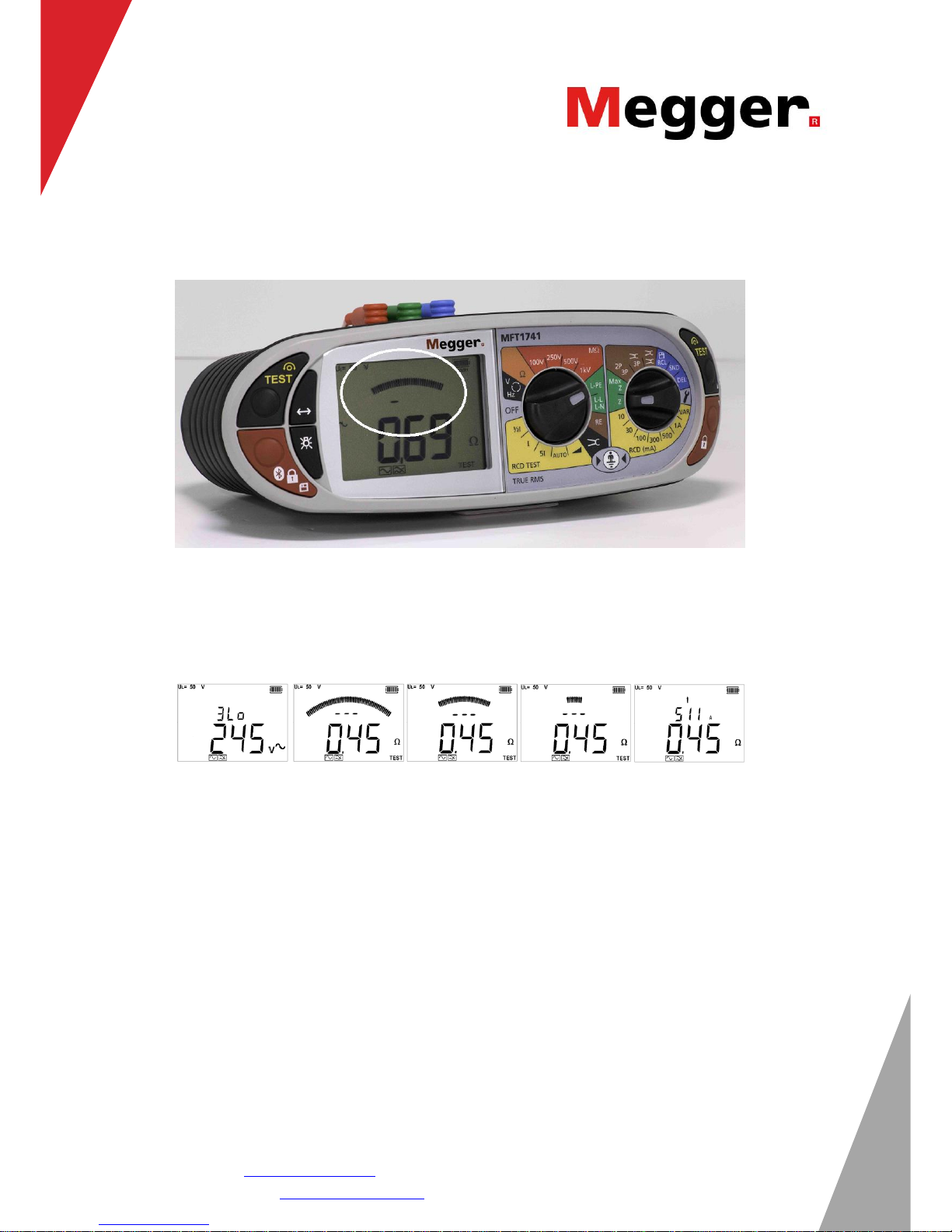
The display shows a full width analogue arc, consisting of 51 elements, refer to Figure 1. At the start of
the test all elements are displayed.
Figure 1. Instrument with arc encircled.
The instrument will then check for any adverse electrical noise. If nothing is found the test sequence will
terminate and display a final value.
The arc closes to one centre element, indicating the maximum degree of confidence in the result, as
shown in the sequence shown in Figure 2.
Figure 2. Arc contracting
On some occasions electrical noise may be detected on the supply during the initial test phase that could
affect the accuracy or repeatability of the measurement. This may consist of random noise or harmonics
(several levels of harmonic distortion may occur), either generated from within the electrical system or
externally from other locations on the same low voltage supply.
This appears as distortion to the AC waveform during the measurement process. The MFT expects the
same AC voltage for the duration of the test. Any deviation from this affects the accuracy of the loop test.
Random variations are created by electrical noise, which in turn, creates random variations in the final
result, with possibly over an ohm of variation in extreme cases.
On detecting noise on the supply the Confidence Meter will continue testing and refining its measurement.
This is shown by the noise symbol the left of the display appearing and the arc closing more slowly,
pausing or even opening up again in high noise situations refer to Figure 3.
Page 3

APPLICATION NOTE
New “Confidence Meter”
adaptive loop impedance meter.
Megger Ltd, Dover, United Kingdom www.megger.com
Sales office: 01304 502 101, uksales@megger.com MFT1741/MFT1845 Confidence Meter
Technical support: 01304 502 120, uksupport@megger.com P3
Figure 3. Arc closing slows as final result is reached
When the confidence meter has refined its measurement, the arc will finally close to one element and the
test will stop. The final displayed result may differ from the original quite significantly refer to Figure 4.
Figure 4. Arc closes to one element after analysing noise.
Extreme noise may cause the loop test measurement to continue for over a minute. In this case the tester
will stop automatically and the size of the arc will indicate how good the meter believes the displayed value
is.
The test can be stopped during the measurement process by pressing the TEST button again.
If the arc is fully closed at the end of the test, the MFT has high confidence in the accuracy of the
measurement. If the arc remains partially closed confidence is lower. This is only indicative of the quality
of the result.
IMPORTANT:
Testing non-RCD protected circuits should always be done with the standard 2Hi test, including non-RCD
protected Phase to Earth circuits, Phase-Neutral circuits or Phase to Phase circuits.
 Loading...