

Page 1

M
MFT1500 Series
Multifunction Tester
Quick Start Guide
Page 2

GSAFETY WARNINGS
■ Safety Warnings and Precautions must be read and understood
before the instrument is used. They must be observed during use.
■ The circuit under test must be switched off, de-energised and
isolated before test connections are made when carrying out insulation
and continuity tests.
■ Continuity of protective conductors and earthed equipotential bonding
of new or modified installations must be verified before carrying out
an earth fault loop impedance test, or RCD test.
■ Circuit connections and exposed metalwork of an installation or
equipment under test must not be touched.
■ The live circuit warning and Automatic discharge are additional safety
features and should not be regarded as a substitute for normal safe
working practices.
■ Do not move the rotary switch positions while a test is in progress.
■ The LCD ‘neon’ voltage indicators cannot reveal a Neutral - Earth
reversal. They cannot be relied upon to identify circuit correctness and
are for guidance only.
■ After insulation tests, capacitive circuits must be allowed to discharge
before disconnecting test leads.
■ The instrument should not be used if any part of it is damaged.
■ Test leads, probes and crocodile clips must be in good order, clean
and with no broken or cracked insulation.
■ Ensure that hands remain behind guards of probes/clips when testing.
■ U.K. Safety Authorities recommend the use of fused test leads when
measuring voltage on high energy systems.
■ Replacement fuses must be of the correct type and rating. Failure to fit
the correctly rated fuse will result in damage to the instrument in the
event of an overload.
NOTE
THE INSTRUMENT MUST ONLY BE USED BY SUITABLY TRAINED AND
COMPETENT PERSONS
Users of this equipment and/or their employers are reminded that Health
and Safety Legislation requires them to carry out valid risk assessments of
all electrical work so as to identify potential sources of electrical danger
and risk of electrical injury such as inadvertent short circuits.
Where the assessments show that the risk is significant then the use of
fused test leads constructed in accordance with the HSE guidance note
GS38 'Electrical Test Equipment for use by Electricians' should be used.
Symbols used on the instrument are:
F Caution: risk of electric shock
G Caution: refer to accompanying notes
t Equipment protected throughout by Double Insulation (Class II)
c Equipment complies with current EU directives.
>500V
G
Equipment must not be connected to installations >500 V.
Page 3
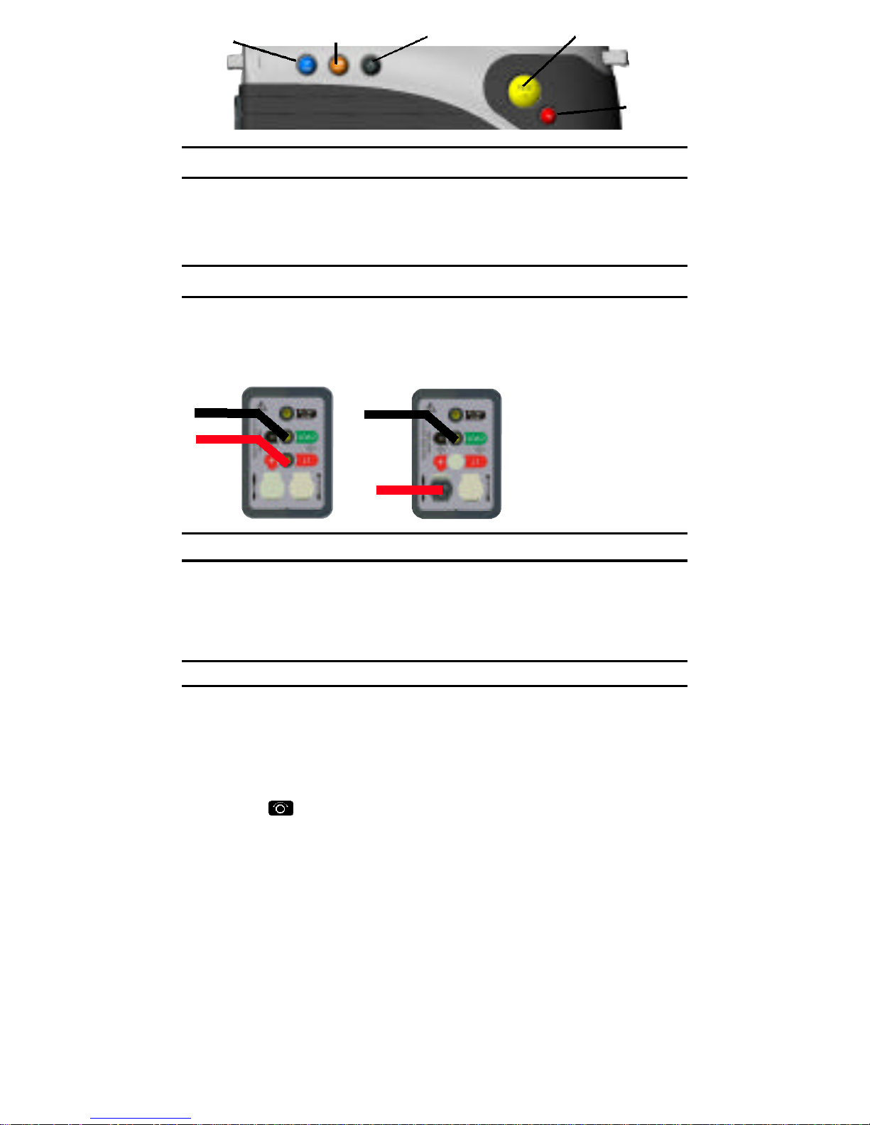
BLUE (0º - 180º) ORANGE (BUZZER)
BLACK (BACKLIGHT) YELLOW (TEST)
RED
(LOCK)
Backlight (MFT1502 only)
Intelligent mode - operates automatically. To switch to manual
mode, press the RED lock and the BLACK backlight buttons
together.
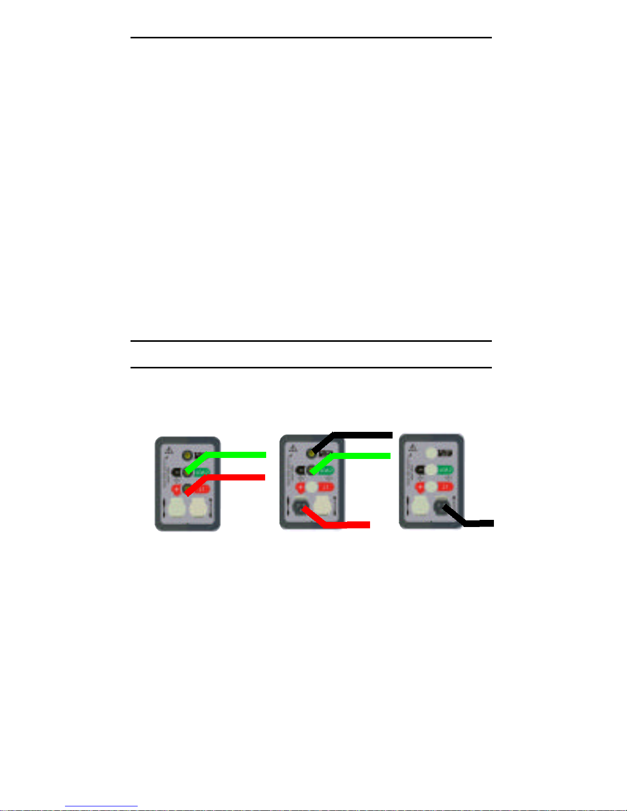
Voltage, Continuity and Insulation testing
BLACK
RED
OPTION 1
2 wire lead
set
BLACK
PROBE
OPTION 2
Switched
probe
Voltage measurement (V)
Range switch set to (V) range
The MFT1500 will automatically display circuit voltage up to
500 V a.c./d.c.
Continuity Measurement [Ω]
Range switch set to [Ω] range
Test Lead options 1 or 2
The MFT1500 will automatically display continuity resistance
when connected.
Lead Null
Short test leads together and press the YELLOW test button on
the instrument or Switched Probe.
Continuity Buzzer (
The buzzer will sound automatically when a circuit is made
(default threshold <2 Ω)
Buzzer Threshold (
Select BUZZER range and press the ORANGE button until
required range is displayed.
Options, 2 Ω, 5 Ω, 10 Ω, 20 Ω, 50 Ω, and 100 Ω
Warning: Ensure the circuit to be tested is disconnected and
isolated before starting testing.
Z
Z
)
)
Page 4
Insulation testing [MΩ]
Range switch set to [250 V, 500 V or 1 kV] range
Test Lead Options 1 or 2
For insulation voltage range select 250 V, 500 V or 1 kV as
required.
Press the YELLOW test button on the instrument or on the
switched probe to activate the test.
Insulation Test lock
Press the YELLOW test and RED lock buttons together to lock on
the insulation test mode.
The warning triangle is displayed during test lock.
To disable test lock press the YELLOW test button again.
Warning:
Hazardous voltages may be continuously present on the test
probes when the test button is locked down.
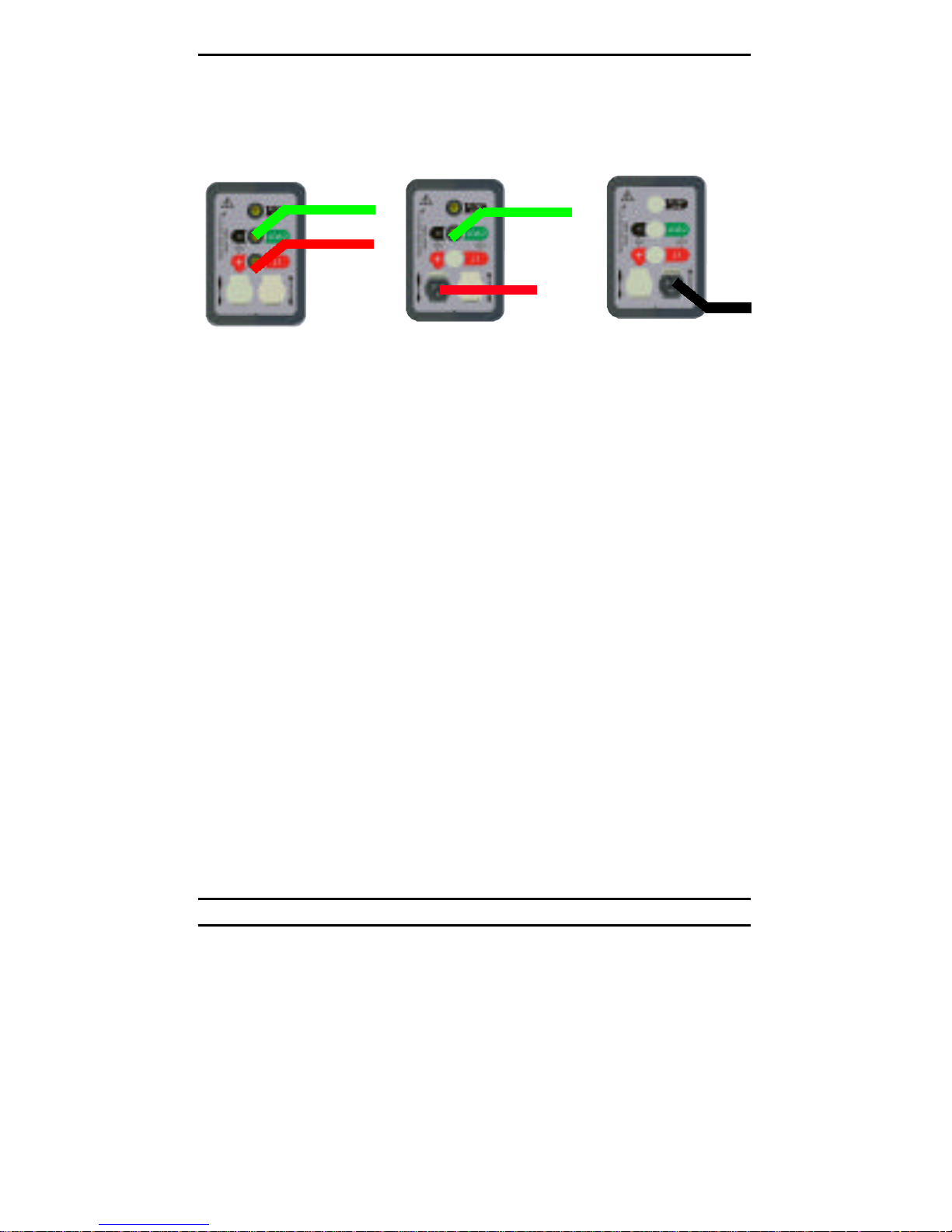
Non tripping loop test [NO TRIP]
OPTION 1
2 wire
measurement
GREEN
RED
OPTION 2
Switched
Probe
BLACK
GREEN
PROBE
Range switch set to the [NO TRIP]
Test Lead Options 1, 2 or 3
NOTE: A 3-Wire connection must be used.
Select when loop testing circuits with RCD protection fitted.
1) Firmly connect the GREEN lead to EARTH, the BLACK lead to
NEUTRAL and the RED lead to PHASE. (Alternatively insert
the plug into an installation socket) (OPTION 3).
2) Supply voltage and polarity are displayed.
3) The test will ‘beep’ and automatically start when a voltage is
detected.
4) Measured L-PE loop value is displayed.
OPTION 3
Mains plug
test lead
The test can be repeated by pressing the YELLOW test button.
Warning: Live voltages present on test circuits during tests.
Page 5
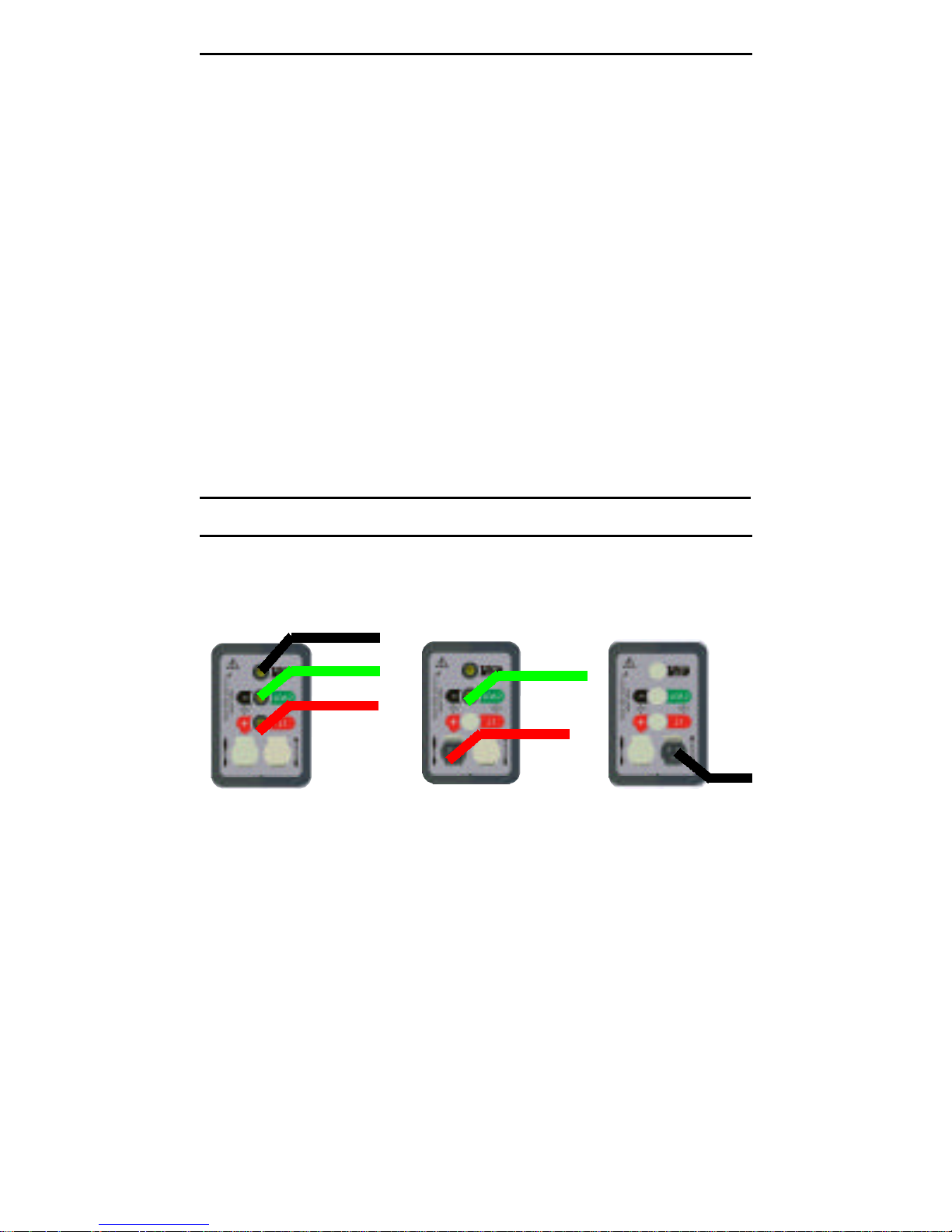
25 A (High current loop test) [25 A]
For use on circuits with NO RCD protection fitted.
OPTION 1
2 wire lead
set
OPTION 2
Switched
probe
GREEN
GREEN
RED
PROBE
OPTION 3
Mains plug
test lead
Warning: The LCD 'Neons' are invalid when using the two wire
connection and should be ignored.
Range switch set to [25 A] range
Test Lead set: Options 1, 2 or 3
Phase-Earth loop impedance
1) Connect the GREEN lead to EARTH and the RED lead to
PHASE or plug into 13 Amp socket.
2) Supply voltage will be displayed.
3) The test will beep and automatically start when voltage is
detected.
4) Measured loop value is displayed.
5) To repeat, press the YELLOW test button.
Phase-Neutral loop impedance
Same connections to instrument as above but connect GREEN
lead to NEUTRAL and RED lead to PHASE.
Phase-Phase loop impedance
Same connections to instrument as above but connect the
GREEN lead to 2nd PHASE and the RED lead to 1st PHASE.
Bonded Metalwork Testing [25 A]
Test Lead set: OPTION 1 or 2
1) Connect the GREEN lead to the bonded metalwork.
2) Connect the RED lead to PHASE.
3) Supply voltage is displayed.
4) The test will ‘beep’ and automatically start when voltage is
detected.
5) Measured resistance value is displayed.
Page 6
PSC Measurement [PSC]
NOTE: High current 25 A measurement only!
Range switch set to [PSC]
Using test lead OPTION 1, 2 or 3 , connect the test leads as
follows:
Phase-Earth PSC
GREEN lead to EARTH and the RED lead to PHASE.
Phase-Neutral PSC
GREEN lead to NEUTRAL and RED lead to PHASE.
Phase-Phase PSC
GREEN lead to 2nd PHASE and the RED lead to 1st PHASE.
1) The supply voltage is displayed and the test will beep, and
automatically start when voltage is detected.
2) Measured PSC result is displayed.
RCD testing
OPTION 1
3 wire
measurement
BLACK
GREEN
RED
1
/2I, I and 5I RCD trip timing [RCD]
Warning: The LCD 'Neons' are invalid when using the two wire
connection and should be ignored.
Test Lead OPTION 1,2 or 3
Select
1
/2I, I or 5I as required.
OPTION 2
Switched
probe
OPTION 3
Mains plug
test lead
GREEN
PROBE
1) Ensure the right hand RCD range switch [mA] is set to the
correct range for the RCD under test.
2) Connect the test leads to the RCD as shown above.
3) Press the YELLOW test button on the instrument or the
switch probe.
1
On
/2I the message >1999 ms is displayed after 2 seconds.
NOTE: The message ‘TrP’ will be displayed if the RCD trips
unexpectedly..
On I the trip time is displayed (or >200 ms if RCD fails to trip).
On 5I the trip time is displayed (or >40 ms if RCD fails to trip).
Page 7
DC test [DC]
Used for testing DC Sensitive RCDs.
Test Lead OPTION 1,2 or 3 as required
1)Select the appropriate RCD rated current on the right hand
rotary switch.
2)Select the [DC] test on the left hand switch.
3) Press the YELLOW test button.
4)The trip time will be displayed .
5)If the RCD fails to trip, ">200 ms" will be displayed.
0º or 180º
On either the I, 5I or DC test, to switch between 0º and 180º
press the BLUE 0°/180° button.
Ramp Test [ ]
Test Lead OPTION 1, 2 or 3 as required
A test current from
RCD should trip.
1) Set the Range select to the RAMP symbol.
2) Set the RCD range switch [mA] to the current rating of the RCD.
3) Press the YELLOW test button.
4) Results are displayed in mA.
5) If RCD fails to trip the message ">***mA" is displayed.
*** = Final test current applied
1
/2I to 1I will be applied during which the
Batteries
Uses 8 x 1.5 V AA (LR6) Alkaline dry cells.
Low battery voltage is indicated by thebsymbol in the display.
To replace batteries, disconnect test leads . Remove the battery
cover and carefully remove the battery carrier.
Replace with new batteries. Do not mix old and new batteries
Warning: OBSERVE CORRECT POLARITY . Incorrect battery
polarity could damage the instrument and invalidate the warranty.
Spare fuse
A blown fuse is indicated by the
Disconnect test lead and remove the battery cover, replace fuse
with spare provided: type: 500 mA (F) HBC 10 kA 500 V
symbol. To replace the fuse:
f
Page 8

M
This instrument is manufactured in the United Kingdom.
The company reserves the right to change the specification or design without prior
n o t i c e .
Megger is a registered trademark.
Part No 6172-812 - Edition 1 - Printed in England - 0503
 Loading...