

Page 1

Digital Loop Tester
M LT7
User Guide
Guide de l’utilisateur
Gebrauchsanleitung
Guía del usuario
SAFETY WARNINGS
✱ Safety warnings and precautions must be read
and understood before the instrument is used.
They must be observed during use.
✱ Continuity of protective conductors and earthed
equipotential bonding of new or modified
installations must be verified before carrying out
an earth fault loop impedance test.
✱ Exposed metalwork of an installation or
equipment under test must not be touched.
✱ LT7 must not be connected across two phases
of a 3 phase supply.
✱ The LCD neon voltage indicators cannot reveal a
Neutral - Earth reversal.
✱ Loop impedance <0,01Ω must be investigated.
✱ Test leads, probes and crocodile clips must be in
good order; clean, and with no broken or cracked
insulation. Avoid drawing excessive arcs on high
current tests.
✱ The mains power cord forms part of the
measuring circuit of the instrument. This test lead
must not be modified or changed in any way, or
be used in any other electrical instrument or
appliance.
✱ The instrument must not be used if any part is
damaged.
✱ Use of the instrument in any unspecified manner
may impair the protection provided.
THE INSTRUMENT MUST ONLY BE USED BY SUITABLY TRAINED AND
Symbols used on the instrument
Caution: refer to accompanying notes.
Equipment protected throughout by Double Insulation
(Class II)
Equipment complies with relevant EU Directives
NOTE
COMPETENT PERSONS
.
Page 2
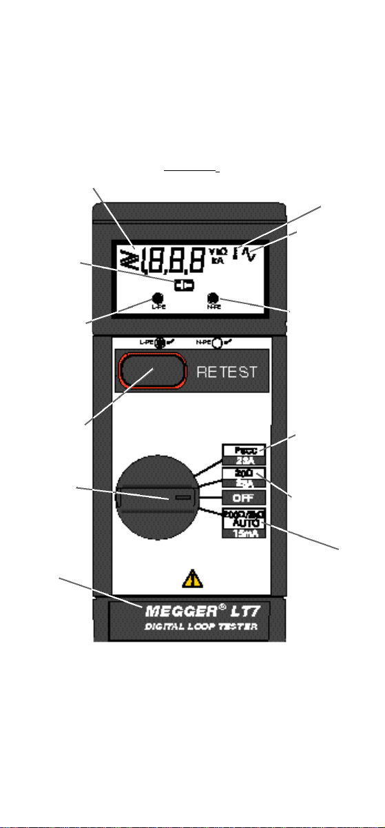
GENERAL DESCRIPTION
The Megger LT7 Digital loop tester is a compact portable instrument
designed to measure earth loop impedance and prospective short circuit
current. A special range is provided to carry out loop measurement on
installations protected by Residual Current Devices ≥30mAwithout causing
the breaker to trip out. The resolution in this range (1Ω) is more than
adequate for this purpose. Should greater resolution be required (0.01Ω)
the conventional 23Arange can be used.
Digital LCD
Low Battery
Indicator
P h a s e / E a r t h
Vo l t a g e
I n d i c a t o r
Retest
Push button
4 Position
R o t a r y
S w i t c h
Battery
Compartment
C o v e r
Features
Thermal
Protection
Indicator
‘Excessive
Noise’
Indicator
Neutral/Earth
Vo l t a g e
I n d i c a t o r
Prospective
Short Circuit
Current
Measurement
High Current
(23A) Loop
M e a s u r e m e n t
Low current
(15mA) Loop
M e a s u r e m e n t
Battery Replacement:
For safety reasons, the battery compartment must not be opened if the test
lead(s) are connected. Undo the two screws in the instrument base to
access the battery compartment, and replace the battery cells. The
instrument will beep. Ensure that correct polarity is observed and that the
cover is correctly replaced.
Page 3
Measurements - General
OPERATION
Live - Earth loop impedance measurement can be made via installation
sockets using the plug terminated test lead, or at any other convenient
point on the installation using the optional dual lead test set. The optional
dual lead test can also be used to carry outLive - Neutralloop impedance
measurement.
Refer to Safety Warnings before using the instrument
Switching ‘On’and testing
Turning the rotary switch will activate the instrument. Alternatively, pressing
the Retest button will re-activate the instrument after ‘Auto shut off’. The
activated instrument will momentarily display all screen segments, followed
by the software version number. When connected to mains voltage of the
correct polarity the L - PE ‘neon’indicator activates and supply voltage
is displayed. If out of voltage range, VOL flashes alternately with the actual
measured voltage.The word ‘null’ is then displayed as an 11 second self
calibration check (‘Auto’ range only) is completed. The instrument then
proceeds to automatically take a measurement. Two pin plug terminated
test leads should be reversed if only the N - PE voltage indicator is
activated. Repeat measurements can be made either by disconnecting
and then reconnecting the instrument (e.g. when using test probes) or by
pressing the Retest button. When operational, the LT7 will carry out a self
calibration every 5 minutes.
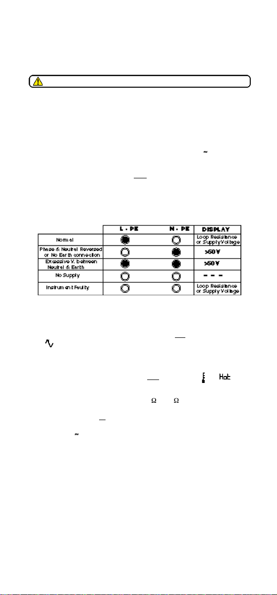
Circuit condition Indication
Testing is inhibited if:
1 ) Phase and Neutral supply connections are reversed. (N - PE‘ n e o n ’ activated).
2) Neutral - Earth voltage >50 V when performing a 3 wire test (L-PE
and N - PE ‘neons’activated).
3) Electrical ‘noise’exceeds rejection level on low current range.
( displayed).
4) Voltage is out of range. Flashing ‘VOL’ and actual Voltage
displayed.
5) Supply frequency out of limits (flashing ‘HZ’ displayed).
6 ) Thermal protection device operates on h i g h current range ( and
d i s p l a y e d ) .
Low Current (Auto) measurement (0,1 or 1 resolution)
This mode measures Live to Earth loop impedance via installation
sockets. Live to Earth or Live to Neutral loop impedance can also be
measured using the optional dual lead test set. The measurement
sequence takes 11 seconds. Residual Current Devices (R.C.D.s) ≥30mA
will not trip.
LT7 is supplied as standard with a display resolution of 0,1 Ω. In areas of
exceptional electrical noise, and where improved repeatability may be
desired, it is possible to change the display resolution to 1 Ω in the
following manner:-
1) Turn rotary switch to the ‘OFF’ position.
2) Press and hold the Retest push button whilst turning the rotary
selector switch to any other position.
3) Still holding the Retest button, the display will cycle between 1 Ω and
0,1 Ω resolution.
4) Release the Retest button when the desired resolution is displayed.
To operate LT7:-
1) Turn rotary switch to ‘Auto’.
2) Connect LT7 by mains cord, or using the dual test lead firmly
connect red test probe to Live and the black test probe to Neutral
or to Protective Earth (ground). Mains (line) voltage is displayed.
3) Test progress is indicated by a sequential display of vertical bars.
Page 4
4) Loop impedance value is displayed directly in . (>2 k displayed if
resistance exceeds 2 kΩ).
High Current (20 ) measurement (0,01 resolution)
This mode measures L i v e t o E a r t h loop impedance via installation sockets o r t h e
L i v et oE a r t h or the L i v et oN e u t r a l loop impedance using the optional dual lead test
set. N o t e: This mode may cause RCDs to trip. The measurement sequence takes
5 seconds.
1 ) Turn rotary switch to ‘ 2 0 ’.
2 )
Connect LT7 by mains cord, or using the dual test lead firmly connect
red test probe to Live and the black test probe to Neutral or to
Protective Earth (ground). Mains (line) voltage is displayed.
3 ) Test progress is indicated by a sequential display of vertical bars.
4 ) Loop impedance value is displayed directly in . N o t e : Any measurement
<0,01Ω will cause the display to flash, and should be investigated.
displayed if resistance exceeds 20Ω).
High Current (PSCC) m e a s u r e m e n t
In this mode, LT7 displays the Prospective Short Circuit Current (calculated at the
nominal supply voltage of 230V divided by loop impedance). This mode can be used
for L i v eto Earthconnection via unprotected installation sockets, o rfor Live toE a r t h ,
o r L i v e to Neutral connection on unprotected circuits using the optional lead set. T h i s
mode may cause RCDs to trip. The measurement sequence takes 5 seconds.
1
) Turn rotary switch to ‘PSCC’.
2) Plug in the LT7, or firmly connect red test probe to Live and black
test probe to Protective Earth (ground) or to Neutral. Mains (line)
voltage is displayed.
3) Test progress is indicated by a sequential display of vertical bars.
4) PSCC value displayed directly in kA. (>20kA displayed if value
exceeds 19,9kA).
Earth Bond Testing
By using the earth bond test lead available as an optional extra, the LT7
can measure the quality of Equipotential bonding within an installation.
1) Turn rotary switch to ‘Auto’or ‘20 ’.
2) Firmly connect the flying lead probe to the metalwork to be tested
and plug the LT7 into a convenient installation socket.
3) Reading displayed will consist of socket supply (live conductor)
impedance plus the impedance of the equipotential earth bonding.
(>20
SPECIFICATION
Ranges:
20 (23Anominal) 0,01Ω - 19,9Ω ±2% ±3 digits (230 V supply)
200 /2k (15mAnominal) 1Ω -1,99kΩ ±2% ±1 digit (230 V supply)
When set to 0,1 Ω resolution ±2% ±3 digits (230 V supply)
PSCC (23Anominal) 0,01 - 0,99 kA
Note: Calibration includes the test leads and plug. To maintain accuracy,
these must not be changed. See note overleaf.
Nominal System Voltage: 110 V / 230 V at 50 Hz
Voltage Accuracy: ±2% ±2 digits (when L-PE neon indicates).
Power supply: 4 x 1,5 V Alkaline cells IEC LR6 type
4 x 1,2 V NiCd or NiMHrechargeable cells
Auto shut off: After 5 minutes of instrument inactivity
Battery life: Typically 1200, one minute tests
Low Battery Indicator: The symbol will appear when A l k a l i n e
battery cells are almost exhausted.
Note: Battery cells should not be left in an instrument which may remain
unused for extended periods of time.
±5% ±6 digits (110 V supply)
±5% ±2 digits (110 V supply)
(±3 digits at 1σ typical)
1,0 - 19,9 kA
or
Page 5

Display: 3 digit L.C.D.
Temperature Range:
Operating: -5˚C to 40˚C (0 - 90% RH non Condensing)
Storage: -25˚C to 65˚C (0 - 95% RH non Condensing at
Thermal Protection: Thermal cut-out will prevent overheating caused
Safety: Meets the requirements for double insulation to IEC1010-1(1995)
EN61010 (1995) at 230 V installation Category III*, without the need for
separately fused test leads. If required, fused test leads are available as an
optional accessory. *Relates to transient overvoltage likely to be found in
fixed installation wiring.
Fuses: - Internal 10A (F) 440 V 10kA ceramic HBC
E.M.C: In accordance with IEC 61326 including amendment No.1
Note: Overvoltage spikes may cause a reset to the original
power ‘On’ state before reverting to normal operation.
Environmental Protection: IP54
Dimensions: 220 mm x 92 mm x 55 mm
Weight: 1200g (including leads, case & battery cells)
Cleaning: Wipe disconnected instrument with a clean cloth
dampened with soapy water or Isopropyl Alcohol (IPA).
4 0 ˚ C )
by repetitive testing on highcurrent range.
- Mains power cord fused plug (when applicable):
10 Amp fuse to BS1362
ACCESSORIES
Supplied Part number
User Guide 6172-087
Power cord test lead with 3 pin plug to BS1363/A 6231-601
Power cord test lead with CEE 7/7 plug 6231-593
Dual test lead with probe 6231-591
Test-&-carry case 6420-092
Optional
Test Lead Set red/balck 6220-437
Crocodile clip, black, for use with dual test lead 6280-284
Earth bond test lead with probe and 3 pin plug 6231-586
to BS1363/A
Fused probe and clip set (2 probes and 3 clips)
1000 V max.10A fuse 6180-405
Power cord
The power cord supplied with your LT7 forms part of the measuring circuit of
the instrument. The overall length of this lead must not be altered.
If the power cord plug is not suitable for your type of socket outlets, do not use
an adaptor. You may change the plug once only by cutting the cord as close
as possible and fitting a suitable plug.
The colour code of the cord is:
If using a fused plug, a 10 Amp fuse to BS 1362 should be fitted.
Note: Aplug severed from the power cord should be destroyed, as a plug
with bare conductors is hazardous in a live socket outlet.
or
Earth (Ground) Yellow / Green
N e u t r a l B l u e
Phase (Line) B r o w n
Page 6

The instrument circuit contains static sensitive devices, and care must be
REPAIR AND WARRANTY
taken in handling the printed circuit board. If the protection of an instrument
has been impaired it should not be used, and be sent for repair by suitably
trained and qualified personnel. The protection is likely to be impaired if, for
example, the instrument shows visible damage, fails to perform the
intended measurements, has been subjected to prolonged storage under
unfavourable conditions, or has been exposed to severe transport
stresses.
New Instruments are Guaranteed for 3 Years from the Date of
Note:
Any unauthorized prior repair or adjustment will automatically invalidate
Instrument Repair and Spare Parts
For service requirements for Megger Instruments contact :-
Megger Limited or Megger
Archcliffe Road Valley Forge Corporate Center
Dover 2 621 Van Buren Avenue
Kent, CT17 9EN Norristown, PA 19403
England U.S.A.
Tel: +44 (0) 1304 502243 Tel: +1 (610) 676-8579
Fax: +44 (0) 1304 207342 Fax: +1 (610) 676-8625
or an approved repair company.
Returning an Instrument for Repair
If returning an instrument to the manufacturer for repair, it should be sent
freight pre-paid to the appropriate address. A copy of the Invoice and of the
packing note should be sent simultaneously by airmail to expedite
clearance through Customs. A repair estimate showing freight return and
other charges will be submitted to the sender, if required, before work on
the instrument commences.
Purchase by the User.
the Wa r r a n t y.
Megger Limited
Archcliffe Road
Dover
Kent CT17 9EN Tel: +44 (0) 1304 502100
England Fax: +44 (0) 1304 207342
4271 Bronze Way
Dallas Tel: +1 (800) 723-2861 (U.S.A. only)
TX 75237-1017 Tel: +1 (214) 330-3203 (International)
U.S.A. Fax: +1 (214) 337-3038
Valley Forge Corporate Center
2 621 Van Buren Avenue
Norristown, PA19403 Tel: +1 (610) 676-8500
U.S.A. Fax: +1 (610) 676-8610
Megger SARL
29 Allée de Villemomble
93340 Le Raincy
Paris Tel: +33 (1) 43.02.37.54
France Fax: +33 (1) 43.02.16.24
This instrument is manufactured in the United Kingdom
The company reserves the right to change the specification or design without prior notice
Megger is a registered trademark
Part No. 6172-087 - Edition 10 - Printed in England - 0503
Page 7

Guide de l’utilisateur
AVERTISSEMENTS DE SECURITE
✱ La continuité des conducteurs de protectionet la mise à
la terre équipotentielle des installations nouvelles ou
modifiées doit etre vérifiée avant d’effectuer un test
d’impédance de boucle de terreaccidentelle.
✱ Les parties métalliques exposées d’une installation ou
d’un équipement en cours de test ne doivent pas être
touchées.
✱ L’instrument ne doit pas être connecté entre deux
phases d’une alimentation triphasée.
✱ L’affichage à cristaux liquides de la tension ne peut pas
afficher un inversement Neutre - Terre.
✱ Les câbles, sondes et pinces crocodiles de test doivent
être en bon état, propres et sans isolation cassée ou
fissurée. Eviter de tirer des arcs excessifs lors des tests
à courant élevé.
✱ Le câble d’alimentation du secteur fait partie du circuit de
mesure de l’instrument. Ce câble de test ne doit pas
être modifié ou changé de quelque façon que ce soit, ou
être utilisé pour un autre instrument électrique.
✱ L’instrument ne doit pas être utilisé si une partie est
endommagée.
✱ L’utilisation de l’instrument de façon non spécifiée peut
affecter la protection fournie.
✱ Les avertissements de securite et les precautions
doivent etre lues et compris avant d’utiliser
l’instrument. Ils doivent etre observes durant
l’utilisation.
L
’INSTRUMENTNE DOITETRE UTILISE QUE PAR DES PERSONNESCOMPETENTES ET
Remplacement des piles
Pour des raisons de sécurité, le compartiment des piles ne doit pasêtre ouvert si
le(s ) câble(s ) est(sont) branchés. Défaire les deux vis à la base de l’instrument
pour accéder au compartiment des piles et remplacer les piles. L’ i n s t r u m e n t
émettra un ‘bip’sonore. S’assurer que la bonne polarité est respectée et que le
cache est bien remis en place.
Mesures - Généralités
La mesure de l’impédance de la boucle Phase - Te r r e peut se faire à travers une
prise de l’installation en utilisant le câble de test à prise, ou bien en tout autre point
pratique sur l’installation en utilisant le câble de test à capteurs en option. Le câble
de test à capteurs en option peut aussi être utilisé pour effectuer la mesure de
l’impédance de la boucle Phase - Neutre.
Voir les Avertissement de Sécurité avant d’utiliser
REMARQUE
FORMEES
FONCTIONMENT
l’instrument.
Mise en ‘Marche’et test
L’instrument sera activé en tournant l’interrupteur rotatif. L’instrument peut aussi être
réactivé en appuyant sur le bouton R e t e s t après son ‘Arrêt A u t o m a t i q u e ’ .
L’instrument affichera momentanément tous les segments de l’écran, suivi du
numéro de version du logiciel. Lorsque connecté à la tension du secteur de la b o n n e
p o l a r i t é , l’indicateur au ‘néon’ L - P E ( P h a s e - Terre) est activé et la tension
d’alimentation est affichée. Le mot ‘ n u l l ’ est ensuite affiché et un contrôle de
calibrage automatique de 11 secondes (Gamme ‘ A u t o ’ uniquement) est eff e c t u é .
L’instrument continue ensuite à relever automatiquement une mesure. Les câbles de
test terminés par une prise à deux fiches doivent être inversés u n i q u e m e n t s i
l’indicateur de tension N - P E ( N e u t r e - Terre) est activé. Des mesures répétées
peuvent être effectuées soit en déconnectant puis en reconnectant l’instrument (par
exemple lors de l’utilisation de sondes de test), soit en appuyant sur le bouton
‘R e t e s t ’. Lorsqu’il fonctionne, le LT 7e ffectuera un calibrage automatique toutes les
Page 8

5 minutes.
Indication de condition du circuit
Le test est bloqué si:
1 ) Les connexions d’alimentation de Phase et Neutre sont inversées
2 ) La tension Neutre - Terre > 50V lors de l’exécution d’un test à 3 fils
3 ) Le ‘bruit’électrique dépasse le niveau de rejet pour la gamme courant
4 ) La fréquence d’alimentation est hors limites (‘H z’clignotant est aff i c h é ) .
5 ) Le dispositif de protection thermique fonctionne pour la gamme de
Mesure (automatique) de courant faible (résolution 1 )
Ce mode mesure l’impédance de la boucle P h a s e à Te r r e au moyen de prises
d’installation, sans faire disjoncter les Interrupteurs de Protection contre les Courants
de Court-circuit ≥30mA( I . P.C.C.). L’impédance de la boucle P h a s e à Te r r eou P h a s e
à N e u t r e peut aussi être mesurée en utilisant l’ensemble de test avec câbles en
option. La séquence de mesure prend environ 11 secondes.
1 ) Mettre l’interrupteur rotatif sur ‘A u t o’ .
2 ) Brancher le LT 7 ou connecter fermement le capteur de test rouge sur
3 ) La progression du test est indiquée par un affichage séquentiel de
4 ) La valeur de l’impédance de la boucleest affichée directement en Ω.
Mesure de courant élevé (20 ) (résolution 0,01 )
Ce mode mesure l’impédance de la boucle P h a s e à Te r r e au moyen de prises
d’installation ou l’impédance de la boucle P h a s e à Te r r e ou P h a s e à N e u t r e e n
utilisant l’ensemble de test avec câbles en option. La séquence de mesure prend
environ 5 secondes.
1 ) Mettre l’interrupteur rotatif sur ‘20 ’ .
2 ) Brancher le LT 7 ou connecter f e r m e m e ntle capteur de test rouge sur
3 ) La progression du test est indiquée par un affichage séquentiel de
4 ) La valeur de l’impédance de la boucleest affichée directement en Ω.
Mesure du Courant Elevé (PSCC)
Dans ce mode, le LT7 a ffiche le Courant Présumé de Court-Circuit (CPC)(calculé à
la tension nominale d’alimentation de 230V, divisée par impédance de boucle). Ce
mode peut être utilisé pour la connexion P h a s e à Te r r e à travers de prises
d’installation non protégées, ou pour la connexion P h a s e à Te r r eou P h a s eà N e u t r e
sur les circuits non protégés en utilisant l’ensemble de test avec câbles en option.
Remarquer que ce mode fera disjoncter les I.P.C.C. La séquence de mesure prend
environ 5 secondes.
1 ) Mettre l’interrupteur rotatif sur ‘ P S C C ’.
2 ) Brancher le LT 7 ou connecter fermement le capteur de test rouge sur
3 ) La progression du test est indiquée par un affichage séquentiel de
4 ) La valeur de CPC est affichée directement en kA. (> 2 0 k A a ffiché si la
Test de la Mise à la Terre
En utilisant le câble de test de mise à la terre disponible en supplément en option, le
LT 7peut mesurer la qualité de la mise à la terre équipotentielle dans une installation.
1 ) Mettre l’interrupteur rotatif sur ‘A u t o’ou ‘20 ’
2 ) Brancher fermement le capteur du câble volant au corps métallique à
3 ) L’ a ffichage comprendra l’impédance de l’alimentation de la prise
(Néon N - P E a c t i v é ) .
( N é o n s L - P E et N - P E a c t i v é s ) .
bas. ( aff i c h é ) .
courant haut ( aff i c h é ) .
P h a s e et le capteur de test noir sur N e u t r e ou sur Terre de Protection
(terre). La tension du secteur est aff i c h é e .
barres verticales.
P h a s e et le capteur de test noir sur N e u t r e ou sur Terre de Protection
(terre). La tension du secteur est aff i c h é e .
barres verticales.
P h a s e et le capteur de test noir sur N e u t r e ou sur Terre de Protection
(terre). La tension du secteur est aff i c h é e .
barres verticales.
valeur dépasse 19,9kA).
tester et brancher le LT 7 dans une prise d’installation pratique.
(conducteur phase) plus l’impédance de la mise à la terre
Page 9

Gebrauchsanleitung
W ARN- UND SICHERHEITSHINWEISE
✱ Vo r der Durchführung einer Scheifenwiderstandsprüfung
Erdungsfehlern m u ß die Kontinuität von Schutzleitern
und geerdeten Ausgleichsabbindungen neuer oder
modifizierter Installationen verifiziert werden.
✱ Freiliegende Metallteile einer geprüften Installation oder
eines Geräts darf nicht berührt werden.
✱ Das Instrument darf nicht über 2 Phasen einer 3 Phase
Versorgung hinweg angeschlossen werden.
✱ Die LCD Neonspannungsanzeigen k ö n n e n eine
Umdrehung Neutral - Erde nicht anzeigen.
✱ Prüflitzen, Sonden und Krokodilklemmen müssen sich in
einem guten Zustand befinden, sauber und ohne
beschädigte oder brüchige Isolierung. Vermeiden Sie das
Ziehen übermäßiger Bögen bei Starkstromsprüfungen.
✱ Das Netzkabel ist Bestandteil des Meßkreislaufs des
Instruments. Dieses Prüfkabel darf nicht modifiziert oder
in irgendeiner Weise verändert werden, oder ineinem
anderen elektrischen Instrument oder Gerät verwendet
werden.
✱ Das Instrument darf nicht eingesetzt werden, wenn ein
Bauteil beschädigt ist.
✱ Der Gebrauch des Instruments zu einem anderen als den
angegeben Zweck kann den verfügbaren Schutz
beeinträchtigen.
✱ Sicherheitshinweise und vorkehrungen müssen gelesen und
verstanden werden, bevor das instrument verwendet wird. Sie
sind während des gebrauchs zu beachten.
DIE INSTRUMENTEDÜRFEN NUR VON AUSREICHEND GESCHULTEN UND
Auswechseln der Batterie
Aus Sicherheitsgründen darf das Batteriefach nicht geöffnet werden,
solange die Prüflitze(n) angeschlossen ist(sind). Lösen Sie die beiden
Schrauben an der Unterseite des Instruments, um das Batteriefach zu
öffnen und wechseln die Batterien aus. Das Instrument sendet einen Ton
aus. Achten Sie auf korrekte Polarität und korrektes Einsetzen der
Abdeckung.
Messungen - A l l g e m e i n
Messung des Spannungsführend - Erde Schleifenwiderstands kann mit der in
einem Stecker endenden Prüflitze über die Installationsbuchse, oder an jeder
beliebigen Stelle auf der Installation mit der zusätzlich erhältlichen Litze mit Sonde,
durchgeführt werden. Die zusätzlich erhältliche Prüflitze mit Sonde kann auch
verwendet werden, um den Schleifenwiderstand Spannungsführend - Neutral z u
m e s s e n .
KOMPETENTENPERSONEN BEDIENT WERDEN
HINWEIS
.
B E T R I E B
Wenden Sie sich vor dem Einsatz des Instruments
an sie Sicherheitshinweise
‘ A n s c h a l t e n ’ und Prüfen
Durch Drehen des Drehschalters wird das Instrument aktiviert. Alternativ reaktiviert
das Betätigen des Wi e d e r h o l u n g s p r ü f k n o p f e s (R e t e st) das Gerät nach dem
‘automatischen Abschalten’. Das Instrument zeigt kurz alle Bildschirmabschnitte an,
gefolgt von der Software Ve r s i o n s n u m m e r. Beim Anschluß an Netzspannung
(Leitung) der korrekten Polarität wird die L - PE ‘ N e o n a n z e i g e ’ aktiviert und die
Versorgungsspannung angezeigt. Daraufhin wird das Wort ‘n u l l’angezeigt während
eine =11 Sekunden dauernde Eigenkalibrierung (nur bei ‘A u t o’Serie) durchgeführt
wird. Das Instrument führt anschließend automatisch eine Messung durch. Zwei
Prüflitzen mit Stiftsteckern sollten umgedreht werden wenn n u r die N - PE A n z e i g e
aktiviert wird. Wiederholungsmessungen können entweder durch Abnehmen und
Wiederanschließen des Instruments an die Installation (z.B. wenn Prüfsonden
verwendet werden) oder durch Betätigen des Wi e d e r h o l u n g s p r ü f k n o p f e s (R e t e s t)
durchgeführt werden. Der LT 7 führt wenn er sich im Betrieb befindet alle 5 Minuten
eine Eigenkalibrierung durch.
Page 10

L e i t u n g s z u s t a n d s a n z e i g e
Die Messung wird verhindert wenn:
1 ) Phase und Neutral Versorgungsanschlüsse umgedreht werden. (N - PE n e o n ’
a k t i v i e r t ) .
2 ) Neutral - Erde Spannung > 50 V bei der Durchführung einer 3-Draht Prüfung
(L- PE und N - PE ‘ N e o n ’a k t i v i e r t ) .
3 ) Elektrisches ‘Geräusch’ übersteigt Unterdrückungsniveau im
Schwachstrombereich. ( angezeigt).
4 ) Versorgungsfrequenz außerhalb Grenzen (blinkende ‘ H z’A n z e i g e ) .
5 ) Wärmeschutzeinrichtung arbeitet im Starkstrombereich ( angezeigt).
Schwachstrommessung (Auto) (1 A u f l ö s u n g )
In diesem Modus wird der Schleifenwiderstand Spannungsführend an Erde ü b e r
Installationsbuchsen gemessen, ohne daß die > 3 0 m A Reststromgeräte (R.C.G)
ausgelöst werden. Der Schleifenwiderstand Spannungsführend an Erde o d e r
Spannungsführend an Neutral kann auch mit dem zusätzlich erhältlichen
Prüflitzensatz gemessen werden. Die Meßsequenz dauert = 11 Sekunden.
1 ) Drehen Sie den Drehschalter auf ‘A u t o’ .
2 ) Stecken Sie den LT 7 ein oder schließen die rote Prüfsonde f e s t a n
Spannungsführend und die schwarze Prüfsonde an die Schutzerdung (Erde)
oder Neutral an. Netzspannung (Leitung) wird angezeigt.
3 ) Der Prüfverlauf wird durch die sequentielle Anzeige der senkrechten Balken
a n g e z e i g t .
4 ) Schleifenwiderstand wird direkt in Ω angegeben.
Starkstrommessung (20 ) (0,01 A u f l ö s u n g )
In diesem Modus wird der Schleifenwiderstand Spannungsführend an Erde ü b e r
Installationsbuchsen o d e r der Schleifenwiderstand Spannungsführend an Erde
oder Spannungsführend an Neutral mit dem zusätzlich erhältlichen Prüflitzensatz
gemessen. Die Meßsequenz dauert = 5 Sekunden.
1 ) Drehen Sie den Drehschalter auf ‘ 20 ‘ .
2 ) Stecken Sie den LT 7 ein oder schließen die rote Prüfsonde fest an
Spannungsführend und die schwarze Prüfsonde an die Schutzerdung (Erde)
oder Neutral an. Netzspannung (Leitung) wird angezeigt.
3 ) Der Prüfverlauf wird durch die sequentielle Anzeige der senkrechten Balken
a n g e z e i g t .
4 ) Schleifenwiderstand wird direkt in angegeben.
Starkstrommessung (PSCC)
In diesem Modus zeigt LT 7 den voraussichtlichen Kurzschlußstrom (VKSS)
(berechnet bei einer Nennversorgungsspannung von 230 V, unterteilt durch
Schleifenwiderstand). an. Dieser Modus kann zur Messung des S p a n n u n g s f ü h r e n d
an Erde Anschlusses über ungeschützte
Spannungsführend an Erde o d e r Spannungsführend an Neutral
Anschlüsse über den zusätzlich erhältlichen Litzensatz auf ungeschützten
Stromkreisen verwendet werden. Beachten Sie, daß die RSG in diesem
Modus ausgelöst werden. Die Meßsequenz dauert = 5 Sekunden.
1 ) Drehen Sie den Drehschalter auf ‘P S C C’ .
2 ) Stecken Sie den LT 7 ein oder schließen die rote Prüfsonde f e s t a n
Spannungsführend und die schwarze Prüfsonde an die S c h u t z e r d u n g ( E r d e )
oder N e u t r al an. Netzspannung (Leitung) wird angezeigt.
3 ) Der Prüfverlauf wird durch die sequentielle Anzeige der senkrechten Balken
a n g e z e i g t .
4 ) V K S S - Wert wird direkt in kA angegeben. (Übersteigt der Wert 19,9kA w i r d
> 2 0 k A a n g e z e i g t ) .
Prüfung der Erdverbindung
Der LT7 kann mit der zusätzlich erhältlichen Erdverbindungs-Prüflitze die
Qualität der Ausgleichsabbindung innerhalb einer Installation gemessen
werden.
1 ) Drehen Sie den Drehschalter auf ‘A u t o’oder ‘ 2 0 ’ .
2 ) Schließen Sie die freie Litzensonde f e s t an das zu prüfende Metallteil an und
stecken den LT 7 in eine passende Installationsbuchse.
3 ) Die angezeigten Werte geben den Widerstand der Buchsenversorgung
(spannungsführenden Leiter) plus den Widerstand der äquipotentialen
Erdabbindung an.
Installationsbuchsen o d e r f ü r
Page 11

Guía del usuario
AVISOS DE SEGURIDAD
✱ La continuidad de conductores de protección y de conexión
equipotencial a tierra de instalaciones nuevas o
modificadas tiene que verificarse antes de llevar a cabo
una prueba de impedancia del bucle de fuga a tierra.
✱ La obra de metal expuesta de una instalación o equipo
sometido a pruebas no deberá tocarse.
✱ El instrumento no deberá conectarse entre dos fases de
una alimentación trifásica.
✱ Los indicadores de tensión de neón de la pantalla de cristal
líquido (LCD) no pueden revelar una inversión Neutro Tierra.
✱ Los cables, sondas y pinzas cocodrilo para pruebas han de
hallarse en buenas condiciones, limpios y sin aislamientos
rotos o agrietados. Evitar arcos excesivos en pruebas de
alta corriente.
✱ El cable de conexión a la red forma parte del circuito de
medición del instrumento. Este cable de prueba no deberá
modificarse o cambiarse en modo alguno, ni ser utilizado en
cualquier otro instrumento o aparato.
✱ El instrumento no deberá utilizarse si tiene alguna pieza
dañada.
✱ La utilización del instrumento de forma no especificada
puede afectar contrariamente la protección que se provee.
✱ Los avisos y precauciones de seguridad han de leerse y
comprenderse antes de utilizar el aparato. Ta m b i e n
deberen
LOS INSTRUMENTOS SOLO DEBERANUTILIZARLOS PERSONAS CAPACITADAS Y
Cambio de las pilas:
Por razones de seguridad, el compartimiento de las pilas no deberá abrirse si está(n)
conectado(s) el (los) cable(s) de prueba. Quitar los dos tornillos de la base del
instrumento para lograr acceso al compartimiento de las pilas y cambiar éstas. El
instrumento emitirá un tono. Cerciorarse de que se respeta la polaridad correcta y de
que la tapa de monta de nuevo correctamente.
Mediciones - Generalidades
La medición de la impedancia del bucle Conductor con corriente - Ti e r r a p u e d e
realizarse a través de las tomas de la instalación usando el cable de prueba
terminado en enchufe, o en cualquier otro punto idóneo de la instalación usando el
conjunto de cable de prueba terminado en sonda opcional. El cable de prueba
terminado en sonda opcional se puede emplear también para llevar a cabo la
medición de la impedancia del bucle Conductor con corriente - Conductor neutro.
NOTE
COMPETENTES
F U N C I O N A M I E N TO
Consultar los avisos de seguridad antes de usar el instrumento
Conexión y prueba
Girando el interruptor giratorio se activará el instrumento. Alternativamente, pulsando
del botón de Repetición de prueba (“Retest”) se reactivará el instrumento después
de su “parada automática” (“Auto shut off”). El instrumento hará visualizar todos los
segmentos de la pantalla, siguiendo después el número de la versión del software.
Cuando se conecta a la tensión de la red (línea) de polaridad correcta, se activa el
indicador de “neón” L - P E y se visualiza la tensión de alimentación. Luego se
visualiza la palabra “nulo” (“ n u l l ” ) mientras se completa una prueba de calibración
en unos 11 segundos (gama “ A u t o ” solamente). Acto seguido, el instrumento
procede a tomar automáticamente una medición. Los cables de prueba terminados
en un enchufe de dos patillas deberán invertirse si s ó l o se activa el indicador de
tensión N - PE. Pueden realizarse mediciones repetidas bien sea desconectando y
reconectando el instrumento (por ejemplo, cuando se usan sondas de prueba) o
pulsando el botón de Repetición de prueba (“Retest”). Durante su funcionamiento,
el LT 7 realizará una autocalibración cada 5 minutos.
Page 12

Indicación del estado de circuitos
La prueba se inhibe si:
1 ) Se invierten las conexiones de alimentación de Fase y Neutro. (Se activa el
“neón” N - PE) .
2 ) La tensión Neutro - Tierra es >50 V cuando se realiza una prueba de 3 hilos. (Se
activan los “neónes” L- PE y N - PE) .
3 ) El “ruido” eléctrico supera el nivel de rechazo en la gama de b a j acorriente. (Se
visualiza ).
4 ) La frecuencia de la alimentación queda fuera de límites. (Se visualiza “ H z ”
p a r p a d e a n d o ) .
5 ) El dispositivo de protección térmica opera en la gama de a l t a corriente). (Se
visualiza ).
Medición (Auto) de la corriente baja (resolución 1 )
Este modo mide la impedancia del bucle Conductor con corriente a Tierra a través
de tomas de la instalación, sin hacer que se disparen los Dispositivos de Corriente
Residual (D.C.R.) ≥30mA. La impedancia del bucle Conductor con corriente a
Ti e r r aodel Conductor con corriente a Neutro se puede medir también utilizando el
conjunto de cable de prueba opcional. En la secuencia de medición se invierten unos
11 segundos.
1 ) Situar el interruptor giratorio en la posición “ A u t o ”.
2 ) Enchufar el LT 7, o conectar f i r m e m e n t e la sonda de prueba roja al
conductorcon corriente y la sonda de prueba negra al N e u t r o o a Ti e r r a
P r o t e c t o r a (masa). Se visualiza la tensión de la red (línea).
3 ) La marcha de la prueba se indica mediante una visualización secuencial de
barras verticales.
4 ) El valor de Impedancia del bucle se visualiza directamente en Ω.
Medición (20 ) de la corriente alta (resolución 0,01 )
Este modo mide la impedancia del bucle Conductor con corriente a Tierra a través
de tomas de la instalación, odel Conductor con corriente a Ti e r r ao del C o n d u c t o r
con corriente a Neutro utilizando el conjunto de cable de prueba opcional. En la
secuencia de medición se invierten unos 5 segundos.
1 ) Situar el interruptor giratorio en la posición “ 2 0 ” .
2 ) Enchufar elLT 7, o conectar f i r m e m e n t e la sonda de prueba roja al C o n d u c t o r
con corriente y la sonda de prueba negra al N e u t r o o a Tierra Protectora
(masa). Se visualiza la tensión de la red (línea).
3 ) La marcha de la prueba se indica mediante una visualización secuencial de
barras verticales.
4 ) El valor de Impedancia del bucle se visualiza directamente en Ω .
Medición de corriente alta (PSCC)
En este modo, el LT 7 muestra en pantalla la Medición de corriente de cortocircuito
previsible (CCP) (calculada a la tensión nominal de alimentación de 230V dividida por
la impedancia del bucle). Este modo se puede utilizar para la conexión C o n d u c t o r
con corriente a Tierra a través de tomas de la instalación no protegidas, o para la
conexión Conductor con corriente a Ti e r r a o Conductor con corriente a Neutro
en circuitos no protegidos usando el conjunto de cable de prueba opcional. Obsérvese
que este modo haría dispararse a los Dispositivos de Corriente Residual (D.C.R.). En
la secuencia de medición se invierten unos 5 segundos.
1 ) Situar el interruptor giratorio en la posición “ P S C C” .
2 ) Enchufar el LT 7, o conectar f i r m e m e n t ela sonda de prueba roja al C o n d u c t o r
con corriente y la sonda de prueba negra a Tierra Protectora (masa) o a
N e u t r o. Se visualiza la tensión de la red (línea).
3 ) La marcha de la prueba se indica mediante una visualización secuencial de
barras verticales.
4 ) El valor de C C P se visualiza directamente en k A. (Se visualizará > 2 0 k A si el
valor excede 19,9 kA).
Prueba de la unión a tierra
Usando el cable de pruebas de la unión a tierra disponible como extra opcional, el LT 7
puede medir la calidad de la conexión equipotencial dentro de una instalación.
1 ) Situar el interruptor giratorio en la posición “ A u t o ” o “ 2 0 ” .
2 ) Conectar f i r m e m e n t e la sonda de cable saliente a la obra de metal que
3 ) La lectura visualizada constará de la impedancia de la alimentación de
haya de someterse a prueba y enchufar el LT 7 en una toma idónea de
la instalación.
la toma (conductor con corriente) más la impedancia de la conexión
equipotencial de tierra.
 Loading...