

Page 1
APPLICATION NOTE
ETK (Earth Test Kit) for Ground Testing
When considering earth (ground) testing, people will often ask about what type of test leads
should be used. This includes questions about the type of wire used, resistance of the leads,
length of the leads, and safety concerns. Fortunately, most of the answers to these questions
are addressed by the design of the earth tester itself.
Because Megger earth testers output a maximum of 50 volts and a maximum current of 50mA,
there are no electrically demanding specifications on the type of wire that can be used for test
leads. Any wire size down to approximately 18 gauge can be used. However, if there is a
requirement to meet IEC61010-1 CAT IV 100V specifications, then the wire used is part of the
system and this must be considered. In this case, there are specific test leads available which
will meet this specification. The low test voltage and current also allay safety concerns relative
to the test leads and the tester.
The earth testers also provide specifications for the maximum resistance in each circuit
(between 50kΩ and 200kΩ for both current and potential) – because this resistance is so high,
there is no practical limitation to the resistance and length of the test leads. It is important to
note that most of the resistance comes from the probe in the ground rather than the wire itself –
that is, compared to the resistance of the probe, the wire resistance is insignificant.
In addition, Megger earth testers will notify the user of any poor connections and whether the
unit is meeting required parameters. So, while the resistance and length of the test leads are
important considerations, the design features of the tester have accounted for this – therefore
the user does not have to do anything to compensate.
It should be noted that stranded wire is used for the test leads – this is to allow ease of use
since solid wire would be difficult to manoeuvre, especially when long distances are required.
Because individual strands can sometimes break with usage over time, it is recommended that
a loop test be performed to ensure that the leads are in good working condition prior to
conducting testing.
Another consideration in earth testing is the probes (or earth test spikes). Some users
mistakenly believe that the probes must be driven deep into the ground. However, the probes
simply need to be deep enough for the earth tester to recognize them. Megger earth testers will
provide a warning to the user if the probes are not deep enough or if they are not making
sufficient contact with the soil to satisfy the tester’s measurement parameters.
Megger USA - Valley Forge Corporate Center
2621 Van Buren Avenue, Norristown, Pennsylvania, 19403, USA
T. 1-610 676 8500 F. 1-610-676-8610
Page 2
APPLICATION NOTE
ETK (Earth Test Kit) for Ground Testing
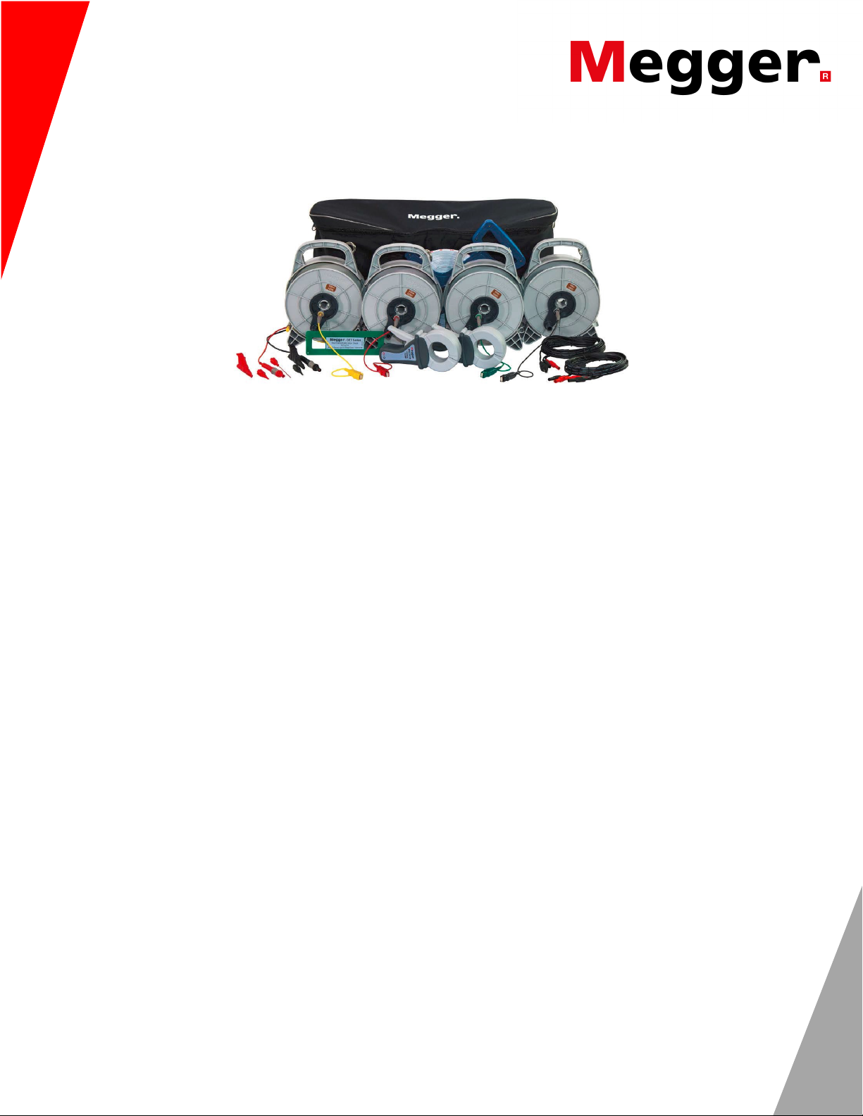
In addition to designing earth testers that address the above concerns, Megger has created new
earth test kits (ETK) which are designed to be practical and allow easy and efficient completion
of earth testing. A carrying bag allows the kits to be protected, neatly stored, and easily
transported.
The test leads are fitted and stored on light-weight reels which have handles and a smooth
action for easy reeling and unreeling. Previous models made it difficult to reel in the test leads
because they had no handles and the reeling action was not smooth. There was also a
tendency for the leads to become tangled inside the reel – this has been solved with the new
larger reel design.
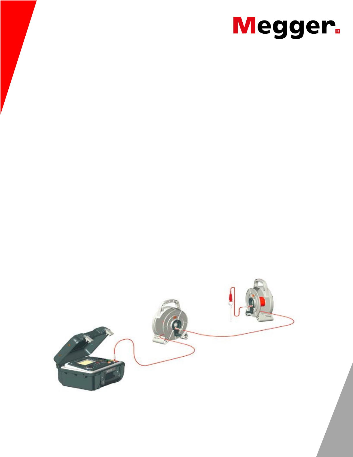
The new design also allows the user to connect a lead to the tester, then carry the reel away to
the reference point. The cable easily unreels as you walk away.
Each reel has clips for holding earth test probes and for securing the ends of the test leads.
These reels can be connected together in a daisy chain to accommodate extra-long lengths for
longer distance applications, such as large substations. The physically large area of a
substation/power station ground system results in a large “resistance area” and, consequently,
long distances to the test probes. Ideally, the current test probe should be placed 10 times the
maximum distance of the ground system (e.g. 3000 feet for a 300 ft2 ground grid) to find the
“flat” portion of the characteristic resistance curve when conducting a Fall of Potential test.!!The
position of the current probe is critical for getting proper measurements; if the distance between
the ground electrode being tested and the current test probe is too short, then the electrical
fields of each will overlap and distort the measurement.
!
Megger USA - Valley Forge Corporate Center
2621 Van Buren Avenue, Norristown, Pennsylvania, 19403, USA
T. 1-610 676 8500 F. 1-610-676-8610
Page 3

APPLICATION NOTE
ETK (Earth Test Kit) for Ground Testing
Other accessories in the kit include: a calibration checker for the tester and one for the test
clamps – this allows the user to ensure functionality and accuracy of the tester and clamps prior
to and following testing; a tape measure to ensure accurate placement of earth test probes; and
test leads with clips for performing continuity tests.
The earth test kits are available in five different combinations to meet a variety of needs and
applications.
Kit combinations include an option for voltage and current test clamps. These allow the user to
perform “stakeless” testing and ART (Attached Rod Technique) methods as well as measuring
leakage currents.
Megger has been a pioneer of Earth/Ground testing since the 1930’s. Over the decades, the
knowledge and techniques developed by Megger have provided the most accurate and trusted
testers in the market. The new ETK models provide the most practical and innovative accessory
kits available, which will allow easy and efficient completion of Earth testing.
Megger USA - Valley Forge Corporate Center
2621 Van Buren Avenue, Norristown, Pennsylvania, 19403, USA
T. 1-610 676 8500 F. 1-610-676-8610
 Loading...