


DPM1000
User guide
EN

G Safety Information
Understand and follow the operating instructions carefully.
G WARNING
Identify hazardous conditions and actions that could cause BODILY HARM or DEATH
■ When using test leads or probes, keep your fingers behind the finger guards.
■ Personal protective equipment should be used if there are ACCESSIBLE HAZARDOUS
LIVE PARTS in the installation where measurement is to be carried out.
■ Remove test leads from meter before opening the battery door or meter case.
■ Use the meter only as specified in this manual; otherwise, the protection provided by
the meter may be impaired.
■ Always use the proper input terminals, switch position, and range for measurements.
■ Verify the meters operation by measuring a known voltage. If in doubt, have the meter
calibrated.
■ Do not apply more than the rated voltage, as marked on the meter, between terminals
or between any terminal and earth.
■ Use caution with voltages above 30 V AC rms, 42 V AC peak, or 60 V DC. These voltages
pose a shock hazard.
■ To avoid false readings that can lead to electric shock and injury, replace the battery as
soon as the low battery indicator blinks.
■ Disconnect circuit power and discharge all high-voltage capacitors before testing
resistance, continuity, diodes, or capacitance.
■ Do not use the meter around explosive gas or vapour.
■ To reduce the risk of fire or electric shock do not expose this product to rain or moisture.
■ Probe assemblies to be used for MAINS measurements shall be RATED as appropriate
for MEASUREMENT CATEGORY III or IV according to EN 61010-031 and shall have a
voltage RATING of at least the voltage of the circuit to be measured.
■ DO NOT USE the test leads if the internal white insulation layer is exposed.
■ DO NOT USE the test leads above maximum ratings of CAT Environment or voltage and
current that are indicated on the probe and probe tip guard.
■ Do not apply a current with a frequency that is higher than the frequency response
range specified in the Electrical Specifications section.
■ Do not apply or remove the clamp or test leads on or around uninsulated hazardous live
conductors where a potential to cause electric shock, electrical burns or arc flash exists.
User Guide www.megger.com
2

G CAUTION
Disconnect the test leads from the test points before changing the position of the function
rotary switch.
Never connect a source of voltage with the function rotary switch in Ω,
position.
Do not expose meter to extremes of temperature or high humidity.
Symbols as marked on the Meter and Instruction manual
F Risk of electric shock
G See instruction manual
d DC measurement
k Both direct and alternating current
t Equipment protected by double or reinforced insulation
Battery
g Earth
a AC measurement
Bluetooth
c Conforms to EU directives
Application around and removal from hazardous live conductors
is permitted
Do not discard this product or throw away.
, and
CATIV
Measurement category IV: Equipment connected between the origin of the low-voltage
mains supply outside the building and the consumer unit.
CATIII
Measurement category III: Equipment connected between the consumer unit and the
electrical outlets.
CATII
Measurement category II: Equipment connected between the electrical outlets and the
user’s equipment.
www.megger.com User Guide
3

Unsafe voltage
To alert you to the presence of a potentially hazardous voltage, when the tester detects a
voltage ≦30 V or a voltage overload (OL) in V, the
symbol is displayed.
Features
■ 10000 Count digital display
■ Active backlight with large scale display
■ VoltSeek (Non-contact voltage detection)
■ Analog bar graph
■ True RMS reading on AC and AC+DC mode
■ Memory Save/Load (up to 1000 records)
■ Data logger (up to 9999 sample values)
■ Bluetooth communication
■ Torch turns on when clamp jaws open
■ Auto selecting 1000 A AC/DC current measurement
■ Auto selecting 1000 V AC/DC voltage measurement
■ 100 kΩ Resistance measurement
■ Continuity beeper
■ Frequency counter
■ Power and power factor measurement
■ Total harmonics distortion
■ Harmonics measurement: 1st to 25th
■ Capacitance capability
■ °C/°F Temperature function
■ Inrush current
■ DCA auto-zeroing button
■ Peak hold
■ Max/Min hold
■ Smart data hold
■ Phase rotation
■ High frequency noise rejection filter
■ Auto power off (APO)
■ CAT IV 600 V/CAT III 1000 V safety standard
User Guide www.megger.com
4

Unpacking and inspection
Upon removing your new Power Clamp Meter from its packing, you should have the
following items:
1. Megger DPM1000 Power Clamp Meter
2. Test lead set (one black, one red)
3. Test probes (one black, one red)
4. Crocodile clips (one black, one red)
5. TP100 Temperature probe
6. User Manual
7. Carry case
8. Batteries
www.megger.com User Guide
5

The Meter Description
1. Jaw
2. VoltSeek LED
3. Jaw trigger
4. Rotary function switch
5. LCD display
6. Function / Operation push
buttons
7. + input terminal
8. Common input terminal
User Guide www.megger.com
6
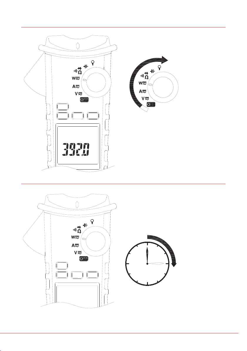
Power On / Off
Auto Power Off
After turning on the meter, the
LCD will show Full, hAlf, and Lo to
indicate the battery capacity.
After 15 minutes of no activity
The meter can operate again by turning it on from the OFF position.
www.megger.com User Guide
7
Auto Power Off (APO) disable:
Press OK button while turning meter on from the OFF position.
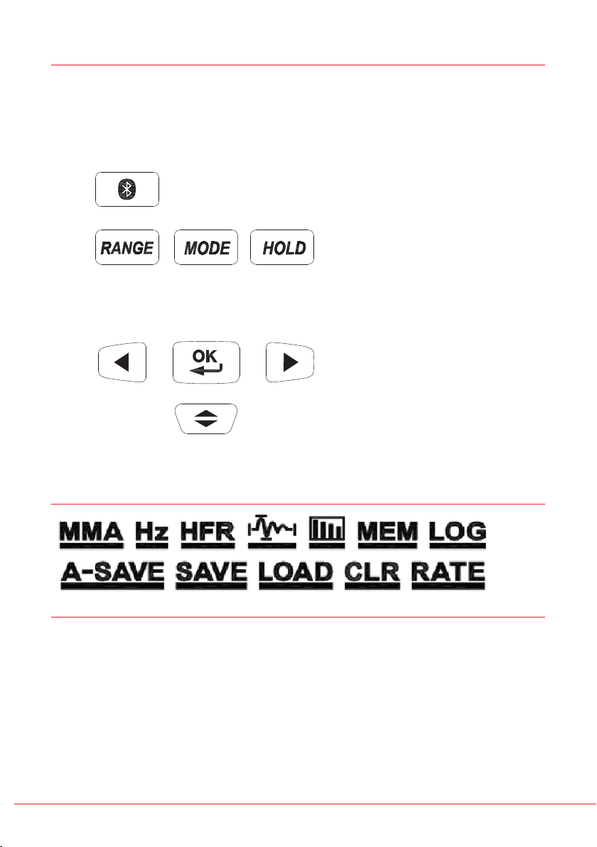
Push Buttons
Bluetooth
LEFT
Menu Operation
RIGHT
UP/DOWN
User Guide www.megger.com
8

Example
Use Arrow keys to move the blinking
cursor to the target icon, and then press
OK button
Use Arrow keys to move the blinking cursor
to the target icon, and then press OK
button for more than 2 sec.
The icon without an underline means the
function is not selected.
The icon with an underline means the
function is selected.
Making basic measurements
Preparation and Caution Before Measurement
G: Observe the rules of G Warnings and G Cautions
The figures on the following pages show how to make basic measurements.
When connecting the test leads to the DUT (Device Under Test) connect the common test
lead before connecting the live test lead. When removing the test leads, remove the live
test lead before removing the common test lead.
www.megger.com User Guide
9

Measuring voltage
G Warning
To avoid an electrical shock, hazard or damage to the meter, do not attempt a
measurement that might exceed 1000 V DC or AC RMS.
User Guide www.megger.com
10
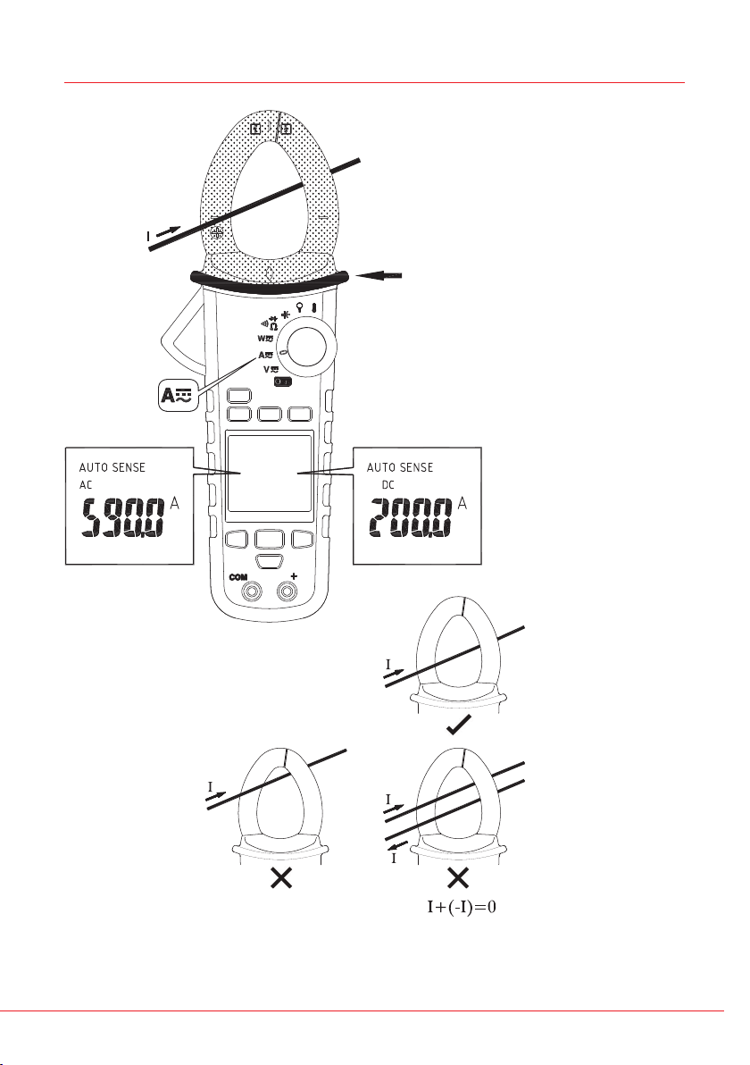
Measuring current
G CAT IV 600 V CAT III
1000 V with respect to
earth for the jaw.
Fixed Barrier hand guard.
G Do not hold the meter
above the fixed barrier
- The torch turns on when the clamp jaws open.
www.megger.com User Guide
11

AUTO SENSE mode:
Displays measurement result for AC only with RMS value or DC value, it depends on
whichever is greater.
AC mode: AC only with RMS value.
DC mode: DC value.
AC+DC mode: AC+DC RMS value.
Note Press MODE button to enter the AC/DC/AC+DC mode.
Press MODE button for more than 2 seconds to return to the AUTO SENSE
mode.
PEAK HOLD (AC mode only)
ACV mode
>2SEC
>2SEC
User Guide www.megger.com
12
 Loading...