

Page 1
DLRO2
Ducter™ Low Resistance Ohmmeter 2 A
User Guide
Page 2

This document is copyright of:
Megger Limited, Archcliffe Road, Dover, Kent CT17 9EN. ENGLAND
T +44 (0)1304 502101 F +44 (0)1304 207342 www.megger.com
Megger Ltd reserves the right to alter the specification of its products from time to time without
notice. Although every effort is made to ensure the accuracy of the information contained within
this document it is not warranted or represented by Megger Ltd. to be a complete and up - to - date
description.
For Patent information about this instrument refer to the following web site:
megger.com/patents
ii
DLRO2
www.megger.com
Page 3

This manual supersedes all previous issues of this manual. Please ensure that you are using the most recent issue of this
document. Destroy any copies that are of an older issue.
Declaration of Conformity
Hereby, Megger Instruments Limited declares that radio equipment manufactured by Megger Instruments Limited
described in this user guide is in compliance with Directive 2014/53/EU. Other equipment manufactured by Megger
Instruments Limited described in this user guide is in compliance with Directives 2014/30/EU and 2014/35/EU where they
apply.
The full text of Megger Instruments EU declarations of conformity are available at the following internet address:
megger.com/company/about-us/eu-dofc
www.megger.com
DLRO2
iii
Page 4

Contents
Contents
1. Introduction ................................................................................................................................... 2
1.1 Product Description ................................................................................................................................. 2
1.2 Features .................................................................................................................................................... 2
1.2.1 Difference Meter .................................................................................................................................... 2
1.3 Applications ............................................................................................................................................. 3
1.4 Company web site ................................................................................................................................... 4
2. Safety Warnings ............................................................................................................................ 5
2.1 Warnings, Cautions and Notes ............................................................................................................... 5
2.1.1 Warnings ............................................................................................................................................... 5
2.1.2 Cautions ................................................................................................................................................ 5
2.1.3 Notes ..................................................................................................................................................... 5
2.2 Safety warnings ....................................................................................................................................... 5
2.3 Test lead safety warnings ....................................................................................................................... 6
2.4 Installation Category Definitions............................................................................................................ 6
2.5 Safety, Hazard and Warning Symbols on the Instrument ..................................................................... 7
2.5.1 Warning Icons ........................................................................................................................................ 7
3. Instrument Controls ..................................................................................................................... 8
3.1 Instrument Layout ................................................................................................................................... 8
3.2 Instrument Display .................................................................................................................................. 9
3.3 Instrument Rotary Control ...................................................................................................................... 10
3.4 Instrument connections and leads.......................................................................................................... 11
3.4.1 External electrical connections of DLRO2 ................................................................................................ 11
3.5 The Difference Meter .............................................................................................................................. 12
3.5.1 Difference Meter example of operation .................................................................................................. 13
4. Setting up the DLRO2 ................................................................................................................... 15
4.1 Warnings and exception conditions ....................................................................................................... 15
4.2 Power ....................................................................................................................................................... 15
4.2.1 First use ................................................................................................................................................ 15
4.2.2 Turn the instrument on and off .............................................................................................................. 15
4.2.3 Battery options ....................................................................................................................................... 15
5. Tests, Inductive mode ................................................................................................................... 16
5.1 Manual stop ............................................................................................................................................. 16
5.1.1 First test ................................................................................................................................................. 16
5.1.2 Second test ............................................................................................................................................ 17
5.2 Auto stop ................................................................................................................................................. 18
5.2.1 First test ................................................................................................................................................ 18
5.2.2 Second test ............................................................................................................................................ 19
iv
DLRO2
www.megger.com
Page 5

Contents
6. Tests, Resistance mode .................................................................................................................. 20
6.1 Auto-start, bidirectional / unidirectional resistance mode ................................................................... 20
6.1.1 Post auto-start, unidirectional test .......................................................................................................... 21
6.1.2 Post auto-start, bidirectional test ............................................................................................................ 21
6.2 Manual, bidirectional / unidirectional resistance mode........................................................................ 22
6.2.1 For a unidirectional test .......................................................................................................................... 23
6.2.2 For a bidirectional test ............................................................................................................................ 23
6.2.3 After the test ......................................................................................................................................... 23
7. Tests, Long leads mode ................................................................................................................. 24
7.1 Long leads mode – auto and manual start ............................................................................................ 24
7.1.1 For manual mode ................................................................................................................................... 25
7.1.2 For auto mode ....................................................................................................................................... 25
8. Error and Warning Conditions...................................................................................................... 27
8.1 Error code categorization ....................................................................................................................... 27
8.2 On screen error messages ....................................................................................................................... 27
8.2.1 Error screen A ........................................................................................................................................ 27
8.2.2 Fuse fail screen ....................................................................................................................................... 27
8.2.3 Error screen B ......................................................................................................................................... 27
9. Settings .......................................................................................................................................... 28
9.1 General settings ....................................................................................................................................... 28
9.2 Language settings ................................................................................................................................... 29
9.3 Instrument Information .......................................................................................................................... 29
9.4 Firmware update ..................................................................................................................................... 29
10. Maintenance ................................................................................................................................ 31
10.1 General Maintenance ............................................................................................................................ 31
10.2 Cleaning ................................................................................................................................................. 31
10.3 Battery .................................................................................................................................................... 31
10.3.1 Battery status ....................................................................................................................................... 31
10.3.2 12 V supply .......................................................................................................................................... 32
10.3.3 Battery Charging .................................................................................................................................. 32
10.3.4 Battery error screens ............................................................................................................................. 32
10.4 Battery Replacement ............................................................................................................................. 33
10.4.1 Replace batteries and remove isolation tab ........................................................................................... 34
11. Specifications ............................................................................................................................... 35
12. Accessories and Equipment ........................................................................................................ 37
12.1 Included Accessories .............................................................................................................................. 37
12.2 Optional Accessories.............................................................................................................................. 37
www.megger.com
DLRO2
v
Page 6

Contents
13. Calibration, Repair and Warranty .............................................................................................. 38
13.1 Return procedure .................................................................................................................................. 38
14. Decommissioning ........................................................................................................................ 39
14.1 WEEE Directive ...................................................................................................................................... 39
14.2 Battery disposal ..................................................................................................................................... 39
15. Notes ............................................................................................................................................ 40
vi
DLRO2
www.megger.com
Page 7

Contents
www.megger.com
DLRO2
vii
Page 8

Introduction
1. Introduction
This user guide details the operational and functional details of the Megger DLRO2 Ducter Low Resistance
Ohmmeter 2 A.
Please read this user guide fully before attempting to use the DLRO2.
1.1 Product Description
The DLRO2 is a tough and truly hand held 2 A low resistance ohmmeter, designed to provide fast, accurate and
repeatable measurements even in electrically noisy environments.
The DLRO2 is designed for ease of use, it can be operated by non-technical users with minimal training.
There are three main measurement modes:
Normal resistance (µΩ).
Fast / long test lead (mΩ).
Inductive resistance (µΩ).
The DLRO2 is supplied with six HR6 rechargeable NiMH cells which can be charged in the instrument using the
supplied external power supply. Non-rechargeable Alkaline AA cells can also be used.
For personal safety and to get the maximum benefit from this instrument, make sure that the safety warnings and
instructions are read and understood before the instrument is used. Refer to 2. Safety warnings on page 5.
Note: This user guide includes instructions for all DLOR2 variants. Some facilities may not be available on your
model of this equipment.
1.2 Features
New ‘Difference Meter’ for quick comparison of results. Refer to 3.5 The Difference Meter on page 12.
Rotary dial test function selection.
Unidirectional or bidirectional test options on normal resistance test mode.
Secondary display field showing either forward and reverse measurement results or previous two test results,
allowing three test results to be on display at any time for easy comparison.
Current reversal capability to cancel standing EMF.
Noisy connection warning, showing when electrical noise or noise from poor clip / probe connections is present.
Test currents selectable from 1 mA to 2 A
Capable of 500 measurements from a single charge.
Supplied with compact CATIII 600 V / CATIV 300 V rated kelvin clip test leads.
1.2.1 Difference Meter
The Difference Meter allows repetitive measurements to be easily compared with an initial reference measurement.
The Difference Meter translates percentage difference to a needle / pointer movement making it easy to see changes
in value.
A new reference measurement can be set at any time at the push of a button.
Refer to 3.5 The Difference Meter on page 12 for further information.
2
DLRO2
www.megger.com
Page 9

Introduction
1.3 Applications
The DLRO2 measures low resistance values in applications ranging from railways and aircraft to resistance of
components in industry.
Any metallic joint can be measured but users must be aware of measurement limitations depending on application.
For example, if a cable manufacturer plans to make resistive measurements on a thin wire, a low test current should
be selected to prevent heating the wire thereby changing its resistance.
This instrument is suited to measuring thick conductors, bonds and quality of welding.
Measurements on electric motors and generators will be inductive and require the user to understand the inductive
mode and charging process before a correct result is achieved.
Electromagnetic noise induced into the leads can interfere with a reading. A noise icon alerts the user, but does not
prevent a measurement.
When dissimilar metals are joined a galvanic effect is created. Users should select a bidirectional mode to make sure
this effect is cancelled. The instrument measures with current flowing in both directions and averages the result.
Aviation – Lightning protection testing measuring mΩ resistance between receptors. Wing tip to wing tip etc.,
using long test leads. Optional long cable reel test leads are available, can be used for assembly of components,
interconnection of equipment, repair and maintenance.
Wind turbines – Lightning protection, measuring mΩ resistance between wing tip to ground connection at base
using long test leads. Optional long cable reel test leads are available.
Rail – Tram and Underground - rolling stock and infrastructure, track high current joints, signalling systems.
Marine - Power wiring systems, protection systems, ship to shore bonding, cathode protection system testing.
Cable laying applications.
Oil and gas pipelines - Bonding between welded joints, grounding systems.
Automotive and EV - Battery connections, weld quality, quality of crimped connections, assembly robot welding
cables.
Cable manufacturers - Quality control, cable length.
Component manufacturers - Quality control.
Space exploration and engineering - structural metal to metal, ground network metal to metal, carbon fibre to
metal, carbon fibre to carbon fibre.
Data Centres - During electrical installation of main panel, generator and UPS systems. Verification of protective
device contact resistance, busbar parallel feeds, busbar lapped joints, optimum resistance over torque and cable
lug to busbar connections. During maintenance using trending data for all aspects of the above, verification
after repair.
Medical hand held opportunity - earthing and bonding systems for protection against microshock and
macroshock.
Panel / Switchgear Manufacturers - End of production line testing, site commissioning, maintenance and fault
finding.
Robotics - Wiring systems and connections which are subject to stress / movement / vibration, bonding of
component parts to minimise static, grounding of machine, welding leads of robot spot welder.
Electrical infrastructure - Cable resistance from one end, cable length, identification of parallel supplies while
connected, cable to lug to connection fault finding, checking assembled connections main supply cables and
panels, switch gear and protective devices, ups and changeover panels, interlinking busbars, interlinking cables,
distribution and PDU boards, lightning protection systems, final circuits.
www.megger.com
DLRO2
3
Page 10

Introduction
1.4 Company web site
Occasionally an information bulletin may be issued via the Megger web site. This may concern new accessories, new
usage instructions or a software update. Please occasionally check on the Megger web site for anything applicable
to your Megger instruments.
www.megger.com
4
DLRO2
www.megger.com
Page 11

Safety Warnings
2. Safety Warnings
The safety instructions given in this document are indicative of safe practice and are not to be considered exhaustive.
Additionally, they are not intended to replace local safety procedures in the region where the instrument is used. If
the equipment is used in a manner not specified by the manufacturer, the protection provided by the equipment may
be impaired.
There are no user replaceable parts within the DLRO2.
2.1 Warnings, Cautions and Notes
This user guide follows the internationally recognized definition of warnings, cautions and notes. These instructions
must be adhered to at all times.
2.1.1 Warnings
Warnings alert the reader to hazardous situations where injury to personnel can occur. They are set in red type
to make them stand out. They are placed before the item to which they relate and repeated at each applicable
occasion.
2.1.2 Cautions
Cautions alert the reader to situations where equipment damage may result if a process is not followed properly.
They are set in bold type. They are placed before the item to which they relate and repeated at each applicable
occasion.
2.1.3 Notes
Notes give additional important information that will help the reader. They are not used when a Warning or Caution
is applicable. They are not safety related and may be placed either before or after the associated text as required.
2.2 Safety warnings
These safety warnings must be read and understood before the instrument is used. Retain for future reference.
Warning: This instrument must be operated only by suitably trained and competent people.
Protection provided by the instrument may be impaired if it is not used in a manner specified by the
manufacturer.
Local Health and Safety Legislation requires users of this equipment and their employers to carry out valid risk
assessments of all electrical work to identify potential sources of electrical danger and risk of electrical injury such
as inadvertent short circuits. Where the assessments show that the risk is significant the use of fused test leads
may be appropriate.
If battery power is lost during the test, then the user will no longer be warned that the load is being discharged.
The user must check by independent means that the load is discharged before breaking connection.
Disconnect all test leads and switch the instrument OFF before opening the battery cover. Covers must be in
place before reconnecting the test leads.
Ensure every cell in the battery compartment is of identical type. Never mix rechargeable and non-chargeable
cells.
This product is not intrinsically safe. Do not use it in an explosive atmosphere.
Protection provided by the instrument may be impaired if it is not used in a manner specified by the
manufacturer.
The voltage warning function will operate only if the instrument is switched on and working correctly.
In the absence of an indication do not assume that there are no hazardous voltages.
www.megger.com
DLRO2
5
Page 12

Safety Warnings
The voltage indicator and current discharge features must be regarded as additional safety features and MUST
not substitute the normal safe working practice which MUST be followed.
The instrument must not be used if any part of it is damaged or if the terminal shutter is missing.
The circuit under test must be switched off, de-energized, securely isolated and proved dead before test
connections are made.
Circuit connections, exposed conductive parts and other metalwork of an installation or equipment under test
must not be touched during testing.
Only Megger approved test leads with right-angled instrument connectors must be used with this instrument.
Test leads must be at least 1 m in length and provide a total loop impedance ≥ 26 mΩ.
When inductive loads are measured it is essential that the current carrying leads are securely clamped to the item
being tested and that they are not removed before any stored charge has been discharged at the end of the test.
Failure to comply with these instructions might result in an arc being produced which might be dangerous for
the instrument and the operator.
All test leads, probes and crocodile clips must be in good order, clean and with no broken or cracked insulation.
Verify the integrity of the test leads before use.
The safe maximum limit of a measurement connection is that of the lowest rated component in the
measurement circuit formed by the instrument, test leads and any accessories.
Ensure that hands remain behind finger guards of probes and clips.
2.3 Test lead safety warnings:
Test leads, including crocodile clips, must be in good condition, clean, dry, and free of broken or cracked
insulation. The lead set or its components must not be used if any part of it is damaged.
The safe maximum limit of a measurement connection is that of the lowest rated component in the
measurement circuit formed by the instrument, test leads and any accessories.
2.4 Installation category definitions:
CAT IV - Measurement category IV: Equipment connected between the origin of the low-voltage mains supply and
distribution panel.
CAT III -Measurement category III: Equipment connected between the distribution panel and electrical outlets.
CAT II - Measurement category II: Equipment connected between the electrical outlets and user’s equipment.
Measurement equipment may be safely connected to circuits at the marked rating or lower. The connection rating is
that of the lowest rated component in the measurement circuit.
6
DLRO2
www.megger.com
Page 13
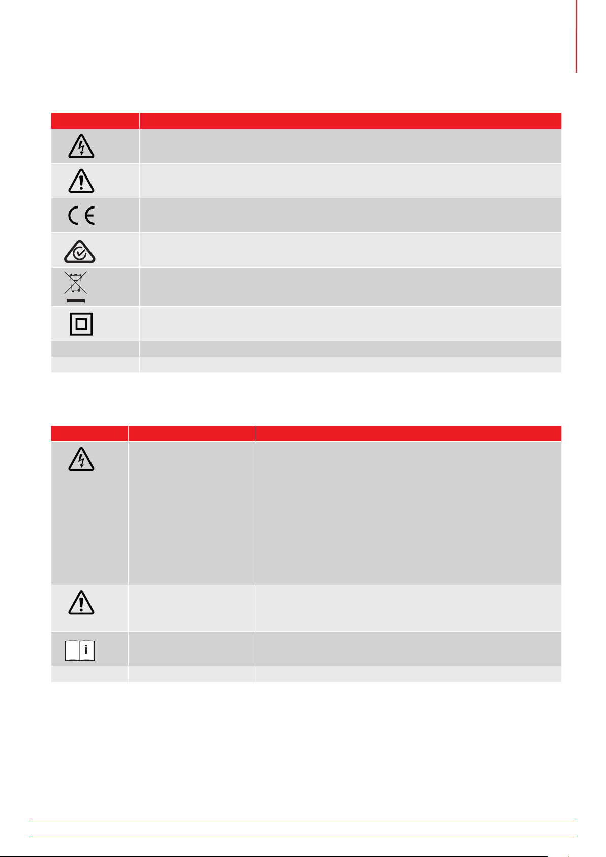
2.5 Safety, Hazard and Warning Symbols on the Instrument
i
This paragraph details the various safety and hazard icons on the instrument’s outer case.
Icon Description
Warning: High Voltage, risk of electric shock
Caution: Refer to User Guide.
Equipment complies with current EU directives.
Equipment complies with current ‘C tick’ requirements.
Do not dispose of in the normal waste stream.
Equipment protected throughout by double insulation.
Safety Warnings
IP54 IP rating
2.5.1 Warning Icons
This paragraph details the warning icons that can show on the display.
Icon Warning Description
External Voltage Warning If an external voltage is applied between the terminals and the
instrument is set to ON, the external voltage warning will flash
on the display. This is a warning that the item under test is live,
it might be dangerous so testing is disabled. The external voltage
warning message will flash if more than 5 V potential difference
is applied between the voltage terminals and the current
terminals. This warning will not show if all terminals are at the
same external voltage.
NOTE: The warning will not operate if the instrument is set to OFF.
Internal Error Warning Internal Error Warning. To clear the error, switch the instrument
OFF and then back ON. Contact Megger if this does not clear
the error.
Read the User Guide Refer to the user guide if this message shows.
www.megger.com
DLRO2
7
Page 14
Instrument Controls
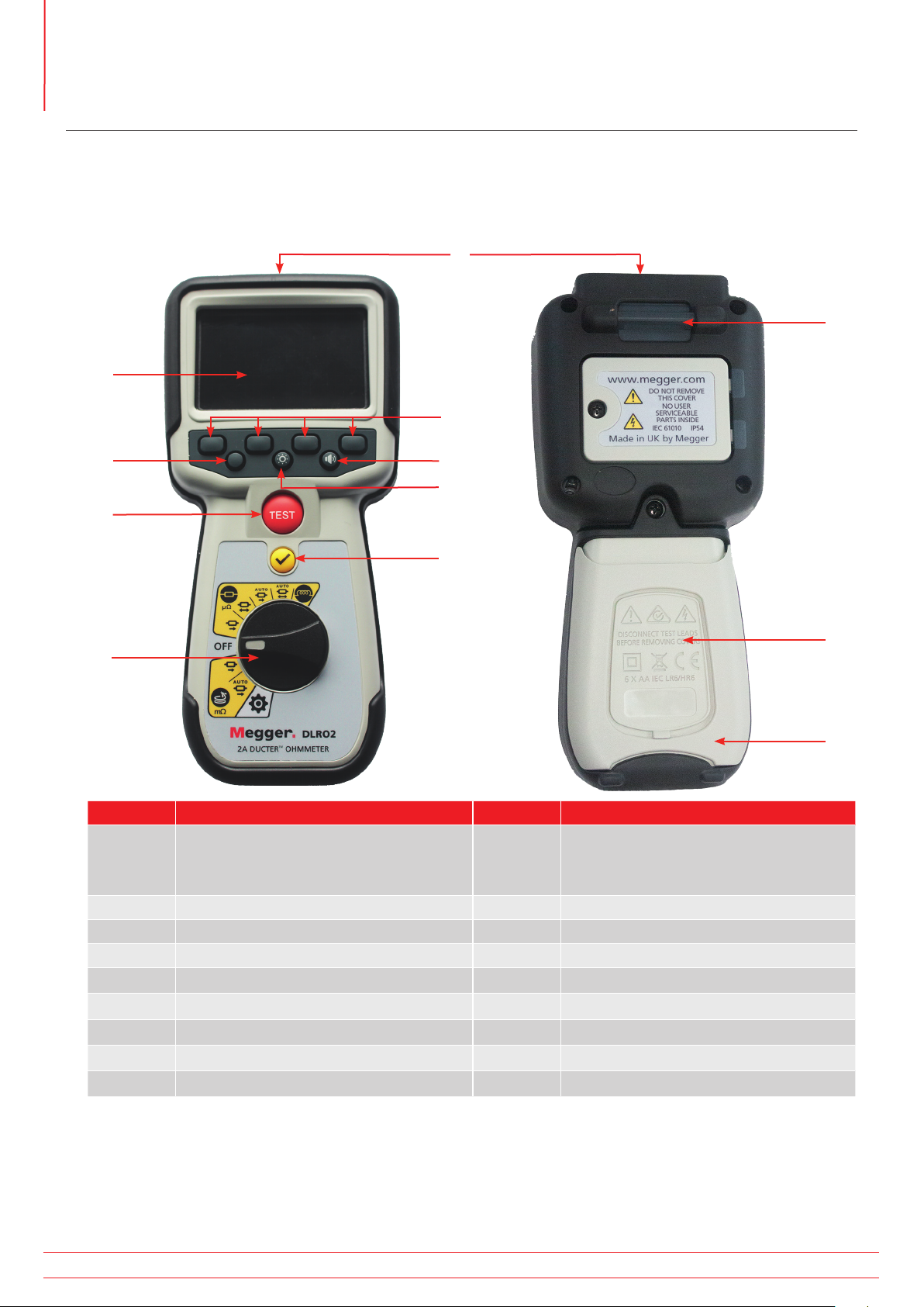
3. Instrument Controls
3.1 Instrument Layout
Front View Rear View
1
2
3
10
6
7
9
Item Description Item Description
1 External electrical connections.
Refer to 3.4.1 External electrical
connections of DLRO2 on page 11
2 Display 11 Battery cover
3 Soft keys (multifunction) 12 Stand
4 Has no function on this model
5 Back-light control
6 Has no fucntion on this model
7 Test
8 TICK button
9 Rotary selection switch
4
5
8
10 Attachment point for strap
11
12
8
DLRO2
www.megger.com
Page 15

3.2 Instrument Display
Instrument Controls
1
16
15
14
13
12
3 4
52
6
7
8
9
10
Item Description Item Description
1 Difference Meter. Refer to 3.5 The
Difference Meter on page 12
2 Operating mode 10 P continuity indicator
3 Primary field 11 Soft keys functions (dependant on rotary
4 Latest result 12 Secondary field
5 Battery condition indicator 13 C continuity indicator
6 Noise indicator 14 Forward measurement result
7 Units of measure (for latest result) 15 Unidirectional or bidirectional selection
8 Reverse measurement result 16 Inductive charge warning
9 Selected test current
selection switch position)
11
www.megger.com
DLRO2
9
Page 16

Instrument Controls
3.3 Instrument Rotary Control
2
3
4
Item Description Item Description
Rotary switch positions
1 Inductive mode 4 Long leads mode
2 Resistance mode 5 Settings mode (grey)
3 Off position
1
5
10
DLRO2
www.megger.com
Page 17

3.4 Instrument connections and leads
3.4.1 External electrical connections of DLRO2
Slider to front Slider to back
Instrument Controls
1
3
2
7
Item Description Item Description
1 Rear attachment point for strap 4 Slider in rear position
2 Slider in front position 5 Battery charger connection
3 Connections: C1, P1, P2, C2 6 USB port (firmware update)
4
5
7 Front
1
7
6
www.megger.com
DLRO2
11
Page 18

Instrument Controls
3.5 The Difference Meter
The Difference Meter is a feature on the DLOR2 that is displayed at the top of the primary screen
(marked ‘1’ on the diagram).
The Difference Meter works in inductive and resistive modes only.
It can be toggled off and on in the instrument settings, giving space for other characters in the primary field to be
displayed in a larger format making them easier to read, if required. Refer to 9.1 General Settings on page 28.
Repetitive measurements can be easily compared with an initial reference measurement. The Difference Meter
translates percentage difference to a needle / pointer movement making it very easy to see change. The green
marker shows the initial or reference reading. Noisy results are shown with a red marker. Good results are shown
with a blue marker.
When testing, pressing the TICK button (
readings recorded on display, including those on the Difference Meter and the secondary field.
1
Item Description Item Description
1 Difference Meter. 4 Blue result marker shows that noise is
2 Red result marker shows that noise
is present. Open circle for latest
result / solid circle for previous
result.
3 Reference measurement, green
) sets the latest reading as the reference reading and cancels all other
2
3
5 Latest measurement showing
4
5
not present. Open circle for latest result
/ solid circle for previous result
percentage difference compared to
initial reference measurement
-7%
Note: All markers are positioned in chronological order. The most recent is positioned high on the Difference Meter
line, the oldest is positioned lowest.
12
DLRO2
www.megger.com
Page 19

3.5.1 Difference Meter example of operation
This explanation of the Difference Meter is written in reference to resistance mode
but the explanation applies equally to inductive mode.
Resistance measurement is selected. The Difference Meter is
inactive. Continuity is indicated for C and P leads
First measurement is complete. The Difference Meter is now
active. The first measurement is shown as a green ring at the
centre of the scale with +0% below.
Instrument Controls
A second measurement is made, the Difference Meter shows
result relative to reference measurement (+30% in this case)
showing an increase. Shown as a blue ring
Note: For each successful measurement the needle leaves
a blue marker on the Difference Meter (a red marker if the
reading contains noise).
Third measurement is made, the Difference Meter shows it’s
result relative to the first (>+1000% in this case) showing an
increase.
The 1000% difference shows clearly that something isn’t
right. Check the leads, connections, unit under test, etc.
Note: The units on the main display have changed from µΩ to
mΩ and are now indicated in blue to highlight the change.
www.megger.com
DLRO2
13
Page 20

Instrument Controls
Fourth measurement is made, the Difference Meter shows
it’s result, again relative to the first measurement.
The new reading is -1% showing a possible return to
the expected result.
Note: The units on the main display have changed back
to µΩ and are shown in blue indicating another change.
Fifth measurement is made, the Difference Meter shows it’s
result, relative to the reference measurement. This reading is
now just -1% lower than the reference measurement.
Note: The units remained unchanged as µΩ and are shown
in black.
14
DLRO2
www.megger.com
Page 21

Setting up the DLRO2
4. Setting up the DLRO2
Before each use visually inspect all equipment about to be used. Check the instrument is in good condition and
there is no visible damage to either the instrument or the test leads. Confirm the instrument case, test leads and
connectors are in good condition with no damaged or broken insulation
4.1 Warnings and exception conditions
Refer to 8. Error and Warning Conditions on page 27.
4.2 Power
4.2.1 First use
NOTE: Before the DLRO2 can be turned on the battery isolation tab must be removed.
1. Remove the battery cover.
2. Pull the battery isolation tab clear of the batteries.
3. Replace cover.
For further details on accessing the battery panel, Refer to 10.4 Battery Replacement on page 33.
4.2.2 Turn the instrument on and off
1. Turn the instrument ON by rotating the rotary switch to the required operating mode (away from the OFF
position).
2. Turn the instrument OFF by rotating the rotary switch to the OFF position.
4.2.3 Battery options
Caution: Do not attempt to recharge alkaline cells, this action is a high potential fire hazard.
The DLRO2 is powered by Internal batteries,
These cells may be used:
6 x LR6 1.5 V Alkaline (AA)
6 x IEC HR6 1.2 V NiMH
The DLRO2 is charged using the supplied mains adapter (NiMH cells only), which will work at voltages between 100 V
and 240 V AC. Ensure the correct battery type is selected in the setting menu. Charging will only occur if the battery
type is set to NiMH. Refer to 9. Settings on page 28.
Warning: Charge NiMH cells only between 0 ºC and 40 ºC ambient temperature.
www.megger.com
DLRO2
15
Page 22

Tests, Inductive mode
5. Tests, Inductive mode
Inductive test mode allows users to measure resistance of an inductive load (i.e. motors, small power transformers,
etc.).
Note: Test current can measure up to 1 A.
Note: Pre-charging; before any measurement can be made, the circuit needs to be ‘pre-charged’.
This is carried out at a low current (1 mA) and is indicated on the display by an animated sequence
of chevrons (< << <<< <<<<).
The animation will be displayed until the pre-charge phase is complete.
Warning: When inductive loads are measured it is essential that the current carrying leads are securely
clamped to the item being tested and that they are not removed before any stored charge has been
discharged at the end of the test. Failure to comply with these instructions might result in an arc being
produced which might be dangerous for the instrument and the operator.
5.1 Manual stop
1. Turn rotary switch to select the inductive mode position.
5.1.1 First test
Inductive test screen appears, ‘Inductive Mode’ shows in
secondary field for a short time then disappears.
Note: Soft key 1 toggles manual / auto stop.
2. Select MANUAL on soft key 1.
3. Connect C1-C2 and P1-P2 to the instrument and the unit
under test.
C and P indicators show red background with
continuity or green background with for good continuity.
Proceed when both show . The continuity indicators are
active during the test and will update if continuity changes.
for no
16
DLRO2
www.megger.com
Page 23

4. To start the test press the TEST button.
Resistance and current values continually up date on screen.
The current starts at 1 mA and can reach a maximum of 1 A if a
higher current is required for the resistance being measured.
End of the test
Tests, Inductive mode
To stop the test press the TEST button. Note: The TICK button (
Warning: Do not disconnect test leads until discharge is completed.
During the discharge phase, the buttons and rotary switch will be inactive. While discharging is still
in progress a warning symbol (F) will flash on the left of the screen and an audible warning buzzer
will sound. Do not remove the test leads until discharge is complete and the warning disappears.
5.1.2 Second test
1. To start the test press the TEST button.
The animated chevron sequence will be displayed during the
pre-charge phase of the measurement, to be replaced by
resistance and current values updating as the instrument
auto-ranges.
Readings continue to update until a stable measurement is
achieved.
2. When the result is stable press the TEST button.
The Difference Meter records the reading.
) will set a new reference value.
End of the test
To stop the test press the TEST button. Note: The TICK button (
Warning: Do not disconnect test leads until discharge is completed.
During the discharge phase, the buttons and rotary switch will be inactive. While discharging is still
in progress a warning symbol (
will sound. Do not remove the test leads until discharge is complete and the warning disappears.
Note: If continuity is lost from either the C or P connection
during a test, this screen will be displayed for 3 seconds.
The DLRO2 will then return to the start of the test.
www.megger.com
) will set a new reference value.
F) will flash on the left of the screen and an audible warning buzzer
DLRO2
17
Page 24

Tests, Inductive mode
5.2 Auto stop
1. Turn rotary switch to select the inductive mode position.
5.2.1 First test
Inductive test screen appears, ‘Inductive Mode’ shows in
secondary field for a short time then disappears.
Note: Soft key 1 toggles MANUAL / AUTO.
2. Select AUTO on soft key 1.
3. Connect C1-C2 and P1-P2 to the instrument and the unit
under test.
C and P indicators show red background with
continuity or green background with for good continuity.
Proceed when both show . The continuity indicators are
active during the test and will update if continuity is lost.
for no
18
DLRO2
www.megger.com
Page 25

Tests, Inductive mode
4. To start the test press the TEST button.
During the test results will live update on screen. The test will
stop automatically when the instrument determines that the
reading has been stable for long enough and is unlikely to
change significantly; the user can override the instrument and
stop the test at any time by pressing the TEST button.
The Difference Meter is active.
When the test is stopped the displayed result is static.
End of the test
When the test stops, either automatically or after the user has pressed the TEST button,
the instrument will enter the discharge phase.
Warning: Do not disconnect test leads until discharge is completed.
During the discharge phase, the buttons and rotary switch will be inactive. While discharging is still in
progress a warning symbol (
sound. Do not remove the test leads until discharge is complete and the warning disappears.
F) will flash on the left of the screen and an audible warning buzzer will
Note: The TICK button (
5.2.2 Second test
1. To start the test press the TEST button.
Previous result moves to secondary display. Primary display
shows 3 dashes till a new valid reading is received.
The readings will update until a stable measurement is
achieved, at which point the instrument will automatically stop
the test. The test can also be stopped at any time by pressing
the TEST button
After the test, the Difference Meter records the reading and
primary screen will show the result.
Note: ‘Two previous results’ in the secondary screen,
left is previous result and right is the result before that.
) will set a new reference value.
Caution: If the reading is unstable the DLRO may not auto stop. The user will need to manually stop the test.
When the test stops, either automatically or after the user has pressed the TEST button,
the instrument will enter the discharge phase.
Warning: Do not disconnect test leads until discharge is completed.
During the discharge phase, the buttons and rotary switch will be inactive. While discharging is still
in progress a warning symbol (
will sound. Do not remove the test leads until discharge is complete and the warning disappears.
Note: The TICK button (
www.megger.com
F) will flash on the left of the screen and an audible warning buzzer
) will set a new reference value.
DLRO2
19
Page 26

Tests, Resistance mode
6. Tests, Resistance mode
Resistance mode measures the resistance of a unit under test in a forward current direction (unidirectional mode) or
forward and reverse direction (bidirectional mode). In manual start mode, the test will be carried out when the TEST
button is pressed. In auto start mode the DLRO2 will start the test automatically as soon as continuity is detected,
however it will not automatically start testing if continuity is established before the test mode is selected.
6.1 Auto-start, bidirectional / unidirectional resistance mode
1. Turn rotary switch to select either the auto-start,
bidirectional resistance mode position or auto-start,
unidirectional resistance mode position.
OR
Resistance test screen appears, ‘Auto-start, Bidirectional
Resistance Mode’ or ‘Auto-start, Unidirectional Resistance
Mode’ shows in secondary field for a short time then
disappears.
Note: Soft key 1 toggles continuous / single test.
Soft keys 2 / 3 cycles through current ratings;
default is 2 A, selectable 1 A, 100 mA, 10 mA, 1 mA.
In bidirectional, soft key 4 toggles between ‘Display
previous 2 results’ and ‘Forward and reverse direction’.
2. Select test settings using the soft keys.
3. Connect C1-C2 and P1-P2 to the instrument and the unit
under test.
C and P indicators show red background with
continuity or green background with for good continuity.
When continuity is detected on both circuits, the C and
P indicators will both be greyed out and the test will start
automatically.
for no
20
If required, to stop the test press the TEST button.
DLRO2
www.megger.com
Page 27

The dashes (or an old result) will flash until a new result
is displayed.
During the test, continuity indicators will fade and soft keys
will be inactive.
For bidirectional tests, the dashes (or the previous result)
and left hand arrow will flash while the instrument performs
a reading in the forward direction. When the forward
measurement is complete, it is shown next to the left hand
arrow, and then the right hand arrow and the dashes (or the
previous result) flash to indicate that the test current has been
reversed.
For unidirectional tests, the dashes (or the previous result) will
flash until a result is ready.
6.1.1 Post auto-start, unidirectional test:
After an auto-start, unidirectional test the C and P continuity
indicators will be grey if continuity was maintained.
This indicates the C or P lead must be disconnected
and reconnected to restart the test.
Tests, Resistance mode
Note: Test button will start another test.
Soft key 1 toggles continuous / single test.
Soft keys 2 / 3 cycles through current ratings;
default is 2 A, selectable 1 A, 100 mA, 10 mA, 1 mA.
Soft key 4 is inactive.
TICK button sets new reference value.
6.1.2 Post auto-start, bidirectional test:
After an auto-start, bidirectional test the C and P continuity
indicators will be grey. This indicates the C or P lead must be
disconnected and reconnected to start the next test.
If an auto-start test is interrupted by pressing the TEST button
C and P continuity indicator will turn grey. This indicates the C
or P lead must be disconnected and reconnected to restart the
test. Alternatively press the TEST button to start another test.
Continuity on C or P has been lost. Re-establish continuity to
start a new test.
www.megger.com
DLRO2
21
Page 28

Tests, Resistance mode
6.2 Manual, bidirectional / unidirectional resistance mode
1. Turn rotary switch to select either the bidirectional
resistance mode position or unidirectional resistance mode
position.
Resistance test screen appears, ‘Bidirectional Resistance Mode’
or ‘Unidirectional Resistance Mode’ shows in secondary field
for a short time then disappears.
Note: Soft key 1 toggles continuous / single test.
Soft keys 2 / 3 cycles through current ratings; default is 2
A, selectable 1 A, 100 mA, 10 mA, 1 mA.
Soft key 4 is only active in bidirectional resistance mode
and toggles between ‘Display previous 2 results’ / ‘Forward
and reverse direction’.
In unidirectional resistance mode soft key 4 is inactive and
will default to ‘Display previous 2 results’.
OR
2. Select test settings using the soft keys.
3. Connect C1-C2 and P1-P2 to the instrument and the unit
under test.
C and P indicators show red background with
continuity or green background with for good continuity.
Proceed when both show .
4. To start the test press the TEST button.
If required, to stop the test press the TEST button.
for no
22
DLRO2
www.megger.com
Page 29

6.2.1 For a unidirectional test:
As the test starts, continuity indicators will fade.
Dashes or previous value will flash on the main display until
result appears.
On the secondary display dashes or previous results will flash
until a new result is ready.
The soft keys will not operate during this test.
6.2.2 For a bidirectional test:
As the test starts, continuity indicators will fade.
The left arrow with dashes will flash first until a result appears,
then the right arrow with dashes will flash until
a result appears.
Dashes or previous value will flash on the main display until
average of the two results appears.
Tests, Resistance mode
On the secondary display dashes or previous results will flash
until a new result is ready.
The soft keys will not operate during this test.
6.2.3 After the test:
For a single test the result is displayed constant in the
main field.
To perform another test press the TEST button (continuity
indicators must be green).
Note: Soft key 1 toggles continuous / single test.
Soft keys 2 / 3 cycles through current ratings; default is 2
A, selectable 1 A, 100 mA, 10 mA, 1 mA.
Soft key 4 is only active in bidirectional resistance mode
and toggles between ‘Display previous 2 results’ / ‘Forward
and reverse direction’.
TICK button sets new reference value.
For a continuous test results in the secondary screen will keep
updating. Tests will be performed back to back.
‘Two previous results’ in the secondary screen, left is previous
result and right is the result before that.
To stop the test press the TEST button.
If continuity is maintained, pressing the TEST button will
start a new test
www.megger.com
DLRO2
23
Page 30

Tests, Long leads mode
7. Tests, Long leads mode
Long leads resistance test mode has been designed for use with test leads of very long length.
The Difference Meter is disabled in long leads mode.
All readings are displayed in mΩ.
Minimum current is 1 A.
Restricted to single tests.
In long leads mode, all soft keys are inactive. The test is pre-set to single measurement,
1 A with previous 2 results displayed.
7.1 Long leads mode - auto and manual start
1. Turn rotary switch to select the long leads mode, either
MANUAL or AUTO position.
OR
Long leads test screen appears, either ‘Long Leads Mode Manual Start’ or ‘Long Leads Mode - Auto Start’ will show in
the secondary field for a short time, the text then disappears to
reveal the previous results fields.
2. Connect C1-C2 and P1-P2 to the instrument and the unit
under test.
C and P indicators show red background with for no
continuity or green background with for good continuity.
24
DLRO2
www.megger.com
Page 31

7.1.1 For manual mode
Tests, Long leads mode
Proceed when both show green background with
3. To start the test press the TEST button.
During the test, continuity indicators will fade.
The dashes (or an old result) will flash until a new result is
displayed.
On the secondary display dashes or previous results will flash
until a new result is ready.
For a single test the result is displayed constant in the main
field. No latest results are displayed in the secondary field
unless multiple tests have been made in this sequence.
.
If continuity is maintained, pressing the TEST button will start
a new test.
7.1.2 For auto mode
In auto-start mode the instrument will start the test when
continuity is established. If both C and P continuity is made
before the test mode is selected, the continuity flags will be
shown in grey – this means that the user must disconnect and
reconnect or press the TEST button to start the test.
During the test, continuity indicators will fade.
The dashes (or an old result) will flash until a new result
is displayed.
On the secondary display dashes or previous results will flash
until a new result is ready.
The test will run automatically.
If required, to stop the test press the TEST button
or break continuity.
www.megger.com
DLRO2
25
Page 32

Tests, Long leads mode
For a single test the result is displayed constant in the main
field. No latest results are displayed in the secondary field
unless multiple tests have been made in this sequence.
Note: The TICK button (
the secondary fields.
Two previous results appear in the secondary fields, left is the
previous result and right is the result before that.
For auto single tests the continuity indicators are grey,
indicating that to repeat the test the leads must be
disconnected and reconnected again.
If the test has been stopped by the TEST button the continuity
indicators will be grey.
If continuity already is shown on the C and P connectors press
the TEST button to re-start the test.
) will clear the previous results in
26
DLRO2
www.megger.com
Page 33

Error and Warning Conditions
8. Error and Warning Conditions
If an error code appears on the display follow the on screen instructions.
8.1 Error code categorization
Item Number Range Description User Action
1 1 - 999 Non dismissible errors Restart unit to recover.
2 1000 - 1999 User dismissible errors
3 2000 - 2999 Auto dismissible errors eg voltage present warning disappears when voltage
4 3000 - .... Logged only errors No user intervention
Press
goes
8.2 On screen error messages
8.2.1 Error screen A
1. Error code.
2. Error text, where applicable, explains what went wrong.
to continue
Remove the message by pressing the TICK button (
8.2.2 Fuse fail screen
1. Error code.
2. Error text, fuse failure.
The fuses in DLRO2 are not user replaceable. If this error screen
appears the instrument must be returned to Megger for repair.
Refer to 13. Calibration, Repair and Warranty on page 38.
8.2.3 Error screen B
1. Error code.
2. Error text, switch the DLRO2 OFF then back ON. If the
problem persists contact Megger.
).
www.megger.com
DLRO2
27
Page 34

Megger DLR02 icons
µΩ
Settings
9. Settings
In this section various user settings can be adjusted or accessed.
9.1 General settings
Switch the rotary switch to the settings mode .
Go to the general settings tab
.
Use soft key 2 to select required setting as listed below.
General settings
Key Press Beep Can be set on or off.
Results Beep Can be set on or off.
Background Colour Toggle between yellow and white using the tick button.
Backlight Timer Use soft keys 2 and 3 to select from off up to 60 seconds (default is 20 seconds).
Battery Technology Toggle between NiMH and alkaline using the tick button.
Difference Meter Toggle ON and OFF using the tick button.
Sleep Timer Press the tick button and navigate using soft keys 2 and 3. Use the tick button to
set.
Restore Factory Settings
Select using the TICK button (
) . When the prompt screen appears, press and
hold the TICK button ( ) for 3 seconds.
Calibration Not user accessible.
28
DLRO2
www.megger.com
Page 35

9.2 Language settings
Switch the rotary switch to the settings mode (Refer to 9.1 General settings on page 28).
Settings
Go to the language settings tab
Use soft keys 2 and 3 to highlight a language, and press the
TICK button (
languages are English, French, German and Spanish.
Changing the set language changes the on screen display
language and the keyboard layout.
) to select the highlighted language. Available
.
9.3 Instrument Information
Switch the rotary switch to the settings mode (Refer to 9.1 General settings on page 28).
Go to the instrument information tab
Instrument information is read only, displaying: GUI version,
measurement version, date of calibration and product serial
number.
.
9.4 Firmware update
The USB port on top of the DLRO2 is for firmware updates only.
There are two parts to a firmware update; the first part
updates the user interface while the second part updates the
measurement firmware. A firmware update file may include
either or both of these. Connect a USB flash drive to the
DLRO2 with the firmware update file in the root directory. The
DLRO2 will automatically update when the instrument is turned
on if a firmware update file is found on the USB flash drive.
1. Plug the USB flash drive in to the USB slot at the top of the
instrument. Turn OFF. Wait 3 seconds and turn back ON.
2. The boot loader screen will be displayed when the
instrument starts up.
3. Press [OK] to upgrade firmware or [TEST] to cancel.
4. The will progress through various stages.
www.megger.com
DLRO2
29
Page 36

Settings
5. When complete, remove the USB flash drive.
6. Restart the DLRO2 (turn off and on).
7. If a measurement firmware update is to be performed,
then the measurement firmware update screen will display.
At the end of the firmware update, the instrument will
automatically restart.
30
DLRO2
www.megger.com
Page 37

Maintenance
10. Maintenance
Note: There are no user replaceable parts within the DLRO2.
10.1 General Maintenance
Test leads should be checked before use for damage and continuity.
Ensure the unit is kept clean and dry after use.
Close all covers when not in use.
10.2 Cleaning
1. Disconnect from mains power.
2. Wipe the instrument with a clean cloth dampened with either water or isopropyl alcohol (IPA).
10.3 Battery
Warning: Always set the instrument to Off and remove test leads before batteries are removed or
installed.
Caution: Old batteries must be disposed of in accordance with local regulations.
Caution: Only use approved batteries as defined below.
Replacement battery types are: 6 x IEC HR6 NiMH (rechargeable) or LR6 AA Alkaline (non rechargeable). Refer to
Specifications on page 34.
Battery technology (battery type) can be selected between alkaline or NiMH. When changing between battery types
always ensure the correct type is selected in the settings menu, failure to do this may result in incorrect battery level
indication and may prevent charging. Refer to 9. Settings on page 28
To help maintain the health, reliability and longevity of the installed batteries:
Ensure if using rechargeable batteries they are fully charged before use (charger supplied).
Store batteries in a cool, dry place. Batteries can be damaged when exposed to heat.
10.3.1 Battery status
Warning: Do not recharge Alkaline batteries.
The battery condition icon is positioned at the top right hand corner of display. This icon is displayed at all times
when the DLRO2 is switched on. When running the icon will indicate state of charge, the icon will be filled in
proportion to the state of charge.
When the battery is in a good state of charge the battery icon will be white and in a low state of charge the battery
icon will flash.
When the battery is very low a large red battery icon will appear in the primary field with the message ‘Battery low
please charge or replace to continue’. No tests will be able to be performed but changes to settings and data
handling can be carried out. The battery must be recharged (NiMH) or replaced (Alkaline) before the DLRO2 can be
used.
When the battery is charging, it will show an animation of the battery from empty to full, then repeats. Once the
battery is full, the animation stops.
The maximum charging time for NiMH batteries is 6 hours, normal charging time is approximately 4 hours.
www.megger.com
DLRO2
31
Page 38

Maintenance
10.3.2 Battery Charging
When charging NiMH rechargeable batteries, only use the power supply provided by Megger. Other power supplies
will not function with the DLRO2. The Megger power supply is designed to preserve the functions and accuracy of
the DLRO2.
Warning: ONLY NiHM batteries are rechargeable.
When charging the DLRO2 while the instrument is OFF, an animated battery will display across the screen to show
charging is taking place. Once the battery is fully charged the screen will display a solid green battery.
Battery charging Battery fully charged
When charging the DLRO2 while the instrument is ON, an animated battery will display in the top right hand corner
of the screen. Tests cannot be performed while the charger is connected. If the TEST button in pressed the buzzer
will sound. However the Settings are fully accessible while the instrument is charging.
10.3.3 Battery error screens
Battery Low
The battery is too low to perform a test.
Charging Fault
A generic charging fault warning screen.
32
Turn off and disconnect the charger. Then reconnect and try
again.
DLRO2
www.megger.com
Page 39

Maintenance
10.4 Battery Replacement
Warning: Remove all test leads before removing the battery cover.
Caution: Batteries should not be left in the instrument if remaining unused for an extended period.
1
2
4
3
No. Description Quantity
1 Screw, captive 1
2 Cover, battery 1
3 Battery isolation tab 1
4 Batteries 6
www.megger.com
DLRO2
33
Page 40

Maintenance
10.4.1 Replace batteries and remove isolation tab
The batteries are housed in the lower section of the DLRO2, behind the rotary switch. Looking at the back of the
instrument, the lower (battery) cover incorporates a stand and has the replacement cell types written on it.
NOTE: If using the DLRO2 for the first time remove and discard the battery isolation tab (3).
1. Remove the test leads and ensure the DLRO2 is switched off.
2. Slacken one captive cross-point screw (1) which is centred at the top of the cover.
3. Battery cover (2) will now lift away from the top.
4. Ease out of lugs at the bottom of the cover.
5. The six batteries (4) can now be lifted out of the compartment.
Caution: Ensure the new cells are replaced in the correct polarity as indicated on the cells and battery
compartment.
Caution: Ensure all batteries are of the same type, do not mix NiMH or Alkaline.
6. Replace all six batteries (4).
7. Replace the battery cover (2) in reverse order to above.
8. Re-secure with screw (1).
9. If the type of batteries has changed (NiMH or Alkaline) ensure the battery technology setting is changed. Refer
to 9. Settings on page 28.
34
DLRO2
www.megger.com
Page 41

Specifications
11. Specifications
Specification Detail
PHYSICAL
Dimensions: 228 x 105 x 75 mm (8.98 x 4.1 x 2.95 in)
Display: Full LCD colour screen with user configurable backlight.
Weight: 905 grams (with batteries)
SAFETY AND ELECTRICAL PROTECTION
Safety rating CATIII 600 V / CATIV 300 V to EN 61010, IEC 61010-031 : 2015, IEC 61010-030
Safety category rating valid to altitude of 3000 m
Live voltage Active live voltage protection to 600 V between any test terminals without blowing a fuse.
LOW RESISTANCE MEASUREMENT
Resistance measurement test modes: Normal test mode, Fast mΩ/long test lead mode and Inductive test mode (Resistance of
Overall resistance range: 1 μΩ – 2000 Ω
Max resistance across C terminals: 2 A with up to 1.1 Ω total resistance and 1 A with up to 3.2 Ω total resistance
Basic accuracy: Bi-directional test current mode: + /- 1% +/- 2 digits
Resistance measurement ranges:
Live voltage warning on display and audible when >5 V is applied between any test terminals.
Fuse protected to 1000 V, fuses are not user changeable.
inductive loads)
Uni-directional test current mode: + /- 1% +/- 10 digits
Inductive mode or unidirectional mode will introduce an undefined error
if an external EMF is present
Full Scale
Test Current Resolution Normal
Resistance
15000 μΩ 2.00 A 1 μΩ
120.00 mΩ 2.00 A 0.01 mΩ
1000.0 mΩ 2.00 A 0.1 mΩ
30.000 mΩ 1.00 A 0.001 mΩ
220.00 mΩ 1.00 A 0.01 mΩ
2000.0 mΩ 1.00 A 0.1 mΩ
300.00 mΩ 100 mA 0.01 mΩ
2500.0 mΩ 100 mA 0.1 mΩ
20.000 Ω 100 mA 0.001 Ω
3000.0 mΩ 10.0 mA 0.1 mΩ
24.000 Ω 10.0 mA 0.001 Ω
200.00 Ω 10.0 mA 0.01 Ω
30.000 Ω 1.00 mA 0.001 Ω
240.00 Ω 1.00 mA 0.01 Ω
2000.0 Ω 1.00 mA 0.1 Ω
Inductive
Resistance
Mode
Mode
Long Test
Lead Mode
(1 A only)
www.megger.com
DLRO2
35
Page 42

Specifications
TEST CURRENT OUTPUT
Normal resistance test mode
Current ranges: 2 A, 1 A, 100 mA, 10 mA and 1 mA
Maximum compliance output voltage: 3.24 V (1 A mode) 2.2 V (2 A mode)
Current output accuracy: Normal and Inductive mode: ±10 %
Long test lead mode: +10 % -0%
At all battery conditions except with low battery indication
Thermal EMF / Seebeck effect
compensation:
ENVIRONMENT
Noise immunity: Less than 1% ±20 digits additional error with 80 mV peak 50/60 Hz with
EMC: IEC61326-1, industrial specification IEC61326-2-2
Dust and moisture ingress: IP54 to IEC60529 in use
Altitude: Operational to 3000 m
Temperature: Operational range 0 ºC to 50 ºC
Humidity: Operational to 95 % Storage to 90 %
Yes, average of forward and reverse test current measurements.
on screen noise indicator.
Less than 1% ±20 digits additional error with 80 mV peak 400 Hz with
on screen noise indicator.
Storage range -20 ºC to 50 ºC
POWER SUPPLY
Rechargeable 6 x HR6 Ni MH batteries with in unit fast charge (also ability to use non-rechargeable Alkaline AA batteries (LR6))
Battery charge time: < 4 hours
Battery life: >1000 bi-directional tests at 2 A into a 1 Ω load
BATTERY CHARGER ADAPTOR:
Mains / line input voltage: 100-240 V
Mains / line input frequency: 47-63 Hz
Output: 12 V DC 1.2 A 14.4 W max.
Type: Travel adaptor / interchangeable plug adaptor
Plug types: Australia, USA, Europe and UK plugs
CONNECTIONS
Test terminals: 4 X 4 mm shrouded sockets
Data: USB (For firmware updates only)
Battery charger: 2.5 mm DC jack connector
User may update instrument firmware to latest version themselves
LANGUAGES
User Interface: English, French, German and Spanish
User guide: English, French, German and Spanish
36
DLRO2
www.megger.com
Page 43

Accessories and Equipment
12. Accessories and Equipment
12.1 Included Accessories
Item Order No.
DLRO2, Ducter Low Resistance Ohmmeter 2 A
Test leads:
Kelvin clip lead set, CAT III 600 and CAT IV 300
Kelvin probe lead set CAT III 600 and CAT IV 300
Accessories:
240 V charger power supply
Batteries: Six 1.2 V NiMH AA 2000mAHR
USB memory stick (with user guide)
Hanging hook and strap
Soft pouch
12.2 Optional Accessories
1012-280
1011-928
1011-929
1002-736
1002-735
1012-068
1012-063
Item Order No.
Test leads:
Set of 4 Kelvin probe pins. Replacement probe tips.
4 right angled adaptors to allow hook terminated (E.g. KC100) leads to fit DLRO2
10 A Fused test probe and clip lead set
DLRO2 current and potential leadset 2m. 2 x red lead, 2 x blk lead, 2 x grabber clip, 2 x probe
Full calibration certificate DLRO2
UKAS calibration certificate DLRO2
1012-064
1012-511
1013-224
1011-673
1013-170
1013-169
www.megger.com
DLRO2
37
Page 44

Calibration, Repair and Warranty
13. Calibration, Repair and Warranty
Megger operate fully traceable calibration and repair facilities to make sure your instrument continues to provide
the high standard of performance and workmanship that is expected. These facilities are complemented by a
worldwide network of approved repair and calibration companies, which offer excellent in-service care for your
Megger products.
For service requirements for Megger instruments contact:
Megger Limited OR Megger
Archcliffe Road Valley Forge Corporate Centre
Dover 2621 Van Buren Avenue
Kent Norristown
CT17 9EN PA 19403
U. K. U. S. A.
Tel: +44 (0) 1304 502 243 Tel: +1 610 676 8579
Fax: +44 (0) 1304 207 342 Fax: +1 610 676 8625
13.1 Return procedure
Warning: Remove the battery cells before shipping this instrument.
UK and USA Service Centres
1. When an instrument requires recalibration, or in the event of a repair being necessary, a Returns Authorisation
(RA) number must first be obtained from one of the addresses shown above. The following information is to be
provided to enable the Service Department to prepare in advance for receipt of your instrument and to provide
the best possible service to you:
Model (for example, DLRO2).
Serial number (found on the display under settings, device information, or on the rear cover and by the
batteries or on the calibration certificate).
Reason for return (for example, calibration required, or repair).
Details of the fault if the instrument is to be repaired.
2. Make a note of the RA number. A returns label can be emailed or faxed to you if required.
3. Pack the instrument carefully to prevent damage in transit.
4. Before the instrument is sent to Megger, freight paid, make sure that the returns label is attached or that the RA
number is clearly marked on the outside of the package and on any correspondence. For items being returned
outside of the UK and USA please send copies of the original purchase invoice and packing simultaneously
by airmail to expedite clearance through customs. In the case of instruments which require repair outside the
warranty period, an immediate quotation can be provided when obtaining the RA number.
5. Track the progress on line at www.megger.com.
38
DLRO2
www.megger.com
Page 45

Decommissioning
14. Decommissioning
14.1 WEEE Directive
The crossed out wheeled bin symbol placed on Megger products is a reminder not to dispose of the product at the
end of its life with general waste.
Megger is registered in the UK as a Producer of Electrical and Electronic Equipment. The Registration No is
WEE/ HE0146QT.
For further information about disposal of the product consult your local Megger company or distributor or visit your
local Megger website.
14.2 Battery disposal
The crossed out wheeled bin symbol placed on a battery is a reminder not to dispose of batteries with general waste
when they reach the end of their usable life.
The battery, is located under the battery cover on the back of the instrument. To remove the battery follow the
instructions in 10.4 Battery Replacement on page 33.
For disposal of batteries in other parts of the EU contact your local Megger branch or distributor.
Megger is registered in the UK as a producer of batteries (registration No.: BPRN00142).
For further information see www.megger.com
www.megger.com
DLRO2
39
Page 46

Notes
15. Notes
40
DLRO2
www.megger.com
Page 47

Local Sales office
Megger Limited
Archcliffe Road
Dover
Kent
CT17 9EN
ENGLAND
T. +44 (0)1 304 502101
F. +44 (0)1 304 207342
Manufacturing sites
Megger Limited
Archcliffe Road
Dover
Kent
CT17 9EN
ENGLAND
T. +44 (0)1 304 502101
F. +44 (0)1 304 207342
Megger USA - Dallas
4545 West Davis Street
Dallas TX 75237
USA
T. 800 723 2861 (USA only)
T. +1 214 333 3201
F. +1 214 331 7399
E. USsales@megger.com
Megger GmbH
Obere Zeil 2 61440
Oberursel,
GERMANY
T. +49 06171 92987 0
F. +49 06171 92987 19
Megger AB
Rinkebyvägen 19, Box 724,
SE-182 17
DANDERYD
T. +46 08 510 195 00
E. seinfo@megger.com
Megger USA - Valley Forge
Valley Forge Corporate Center
2621 Van Buren Avenue
Norristown
Pennsylvania, 19403
USA
T. +1 610 676 8500
F. +1 610 676 8610
Megger USA - Fort Collins
4812 McMurry Avenue
Suite 100
Fort Collins CO 80525
USA
T. +1 970 282 1200
This instrument is manufactured in the United Kingdom.
The company reserves the right to change the specification or design without prior notice.
Megger is a registered trademark
The Bluetooth
®
word mark and logos are registered trademarks owned by Bluetooth SIG,
Inc and is used under licence.
DLRO2--2012-833_UG_EN_V01 07 2020
© Megger Limited 2020 www.megger.com
 Loading...