

Page 1
DLRO2
Ducter™ Low Resistance Ohmmeter 2 Amp
New ‘Difference Meter’ for quick
data comparisons
Use long leads at 1 A without compromising
test speed
Safely test the resistance of inductive loads at 1 A
Up to 600 V active protection against inadvertent
live connections without blowing a fuse
Ideal for outdoor use with protection against dust
and moisture to IP54
Industry standard safety rated at
CATIII 600 V/CATIV 300
DESCRIPTION
The DLRO2 is a tough, hand-held 2 Amp low resistance
ohmmeter. It’s designed to provide fast, accurate,
repeatable measurements, even in electrically noisy
locations. The DLRO2 is the latest in a long line of
instruments to proudly display the Ducter™ brand, the
Ducter™ testers being as well-known and relied upon as
Megger insulation resistance testers.
For the utility or industrial user, a high level of safety
is provided with a CATIII 600 V/CATIV 300 V rating to
IEC61010. In addition, the instrument can protect itself
from inadvertent connections to up to 600 V without
blowing a fuse, thereby avoiding essential time lost due to
repairs or finding a replacement fuse.
When working outside, the IP54 rating ensures that neither
rain nor dust will prevent testing.
The DLRO2 measures low resistance values across a wide
range of applications, from railways and aircraft to the
resistance of industry components.
Applications requiring long test leads are not a problem for
the DLRO2 as it has a dedicated long lead test to optimize
the output. The long test lead function is able to provide
up to 1 A of test current into 4 ohms resistance. This makes
the DLRO2, with its optional cable reel test leads, ideal
for testing wind turbine and avionic lightning protection
applications.
To allow testing of smaller inductive loads, the DLRO2 can
apply 2 A for at least 15 seconds, made possible by the
high-capacity built-in rechargeable batteries, together with
a separate inductive load function. The batteries can be fully
recharged in 2.5 hours, minimizing down time.
Note: The DLRO2 is not ATEX/intrinsically safe rated and
must not be used in explosive gas environments.
FEATURES
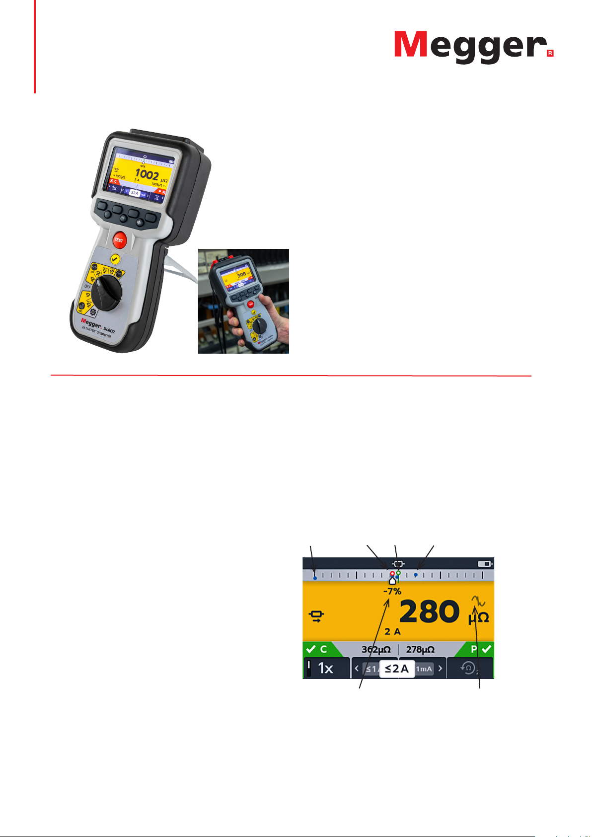
New Difference Meter
The DLRO2 is also equipped with a new innovative
feature called a ‘difference’ meter. This allows repetitive
measurements to be easily compared with an initial
reference measurement. The difference meter translates
percentage difference to a needle/pointer movement to
make it visually easy to see change.
New reference measurements can be set at the
push of a button.
1
3
2
4
56
DLRO2 color display with new Difference Meter
Key to Difference Meter screen:
1 Difference Meter scale
2 Previous result markers in red indicates noise was present
3 Reference measurement
4 Previous result markers
5 Electrical noise warning
6 Percentage difference between current measurement and
initial reference measurement
Page 2

DLRO2
Ducter™ Low Resistance Ohmmeter 2 Amp
DLRO2 keeps you testing and produces reliable
measurements
To ensure the DLRO2 is always ready to test, the supplied
fitted as standard AA rechargeable NiMH batteries can
easily be swapped for non-rechargeable standard AA
alkaline batteries to keep you testing.
The DLRO2 provides 1% accuracy with a focus on
repeatability making it ideal for repeated quality tests in
production environments.
FEATURES AND BENEFITS
n Easily select functions using the rotary dial.
n Option to run the test in bidirectional mode or in
unidirectional mode to save time and battery power.
n The ability to view 3 results on the screen at any time
makes it ideal for 3-phase systems.
n Overcome the effects of standing EMF voltages using
the bidirectional test mode. Forward and reverse
results can be viewed on the secondary display.
n For stability of results, the instrument will warn you
when electrical noise, or noise from poor clip/probe
connections, is present.
n Keeps testing as long as you can, with as many as
500 x 2 A - 3 second tests from a full charge.
n Supplied with compact CATIII 600 V/CATIV 300 V
rated kelvin clip test leads.
EXAMPLE APPLICATIONS
n Aviation – lightning protection testing measuring mΩ
resistance between receptors, wing tip to wing tip
etc., using long test leads. Optional long cable reel
test leads are available, can be used for assembly of
components, interconnection of equipment, repair
and maintenance.
n Wind turbines – lightning protection, measuring mΩ
resistance between wing tip to ground connection at
base using long test leads. Optional long cable reel
test leads are available.
n Rail, tram and underground – rolling stock and
infrastructure, track high current joints, signalling
systems.
n Marine – power wiring systems, protection systems,
ship-to-shore bonding, cathode protection system
testing and cable laying applications.
n Oil and gas pipelines – bonding between welded
joints and grounding systems.
n Automotive and EV – battery connections, weld
quality, crimped connections quality, assembly robot
welding cables.
n Cable manufacturers – quality control, cable length.
n Component manufacturers – quality control.
n Space exploration and engineering – structural metal
to metal, ground network metal to metal, carbon
fiber to metal, carbon fiber to carbon fiber.
n Data centers – during electrical installation of main
panel, generator and UPS systems. Verification of
protective device contact resistance, busbar parallel
feeds, busbar lapped joints, optimum resistance over
torque and cable lug to busbar connections. During
maintenance using trending data for all aspects of the
above, verification after repair.
n Medical hand-held opportunity – grounding and
bonding systems for protection against microshock
and macroshock.
n Panel/switchgear manufacturers – end of production
line testing, site commissioning, maintenance and
fault finding.
n Robotics – wiring systems and connections which
are subject to stress/movement/vibration, bonding
of component parts to minimize static, grounding of
machine, welding leads of robot spot welder.
n Electrical infrastructure – cable resistance from one
end, cable length, identification of parallel supplies
while connected, cable to lug to connection fault
finding. Checking assembled connections main supply
cables and panels, switchgear and protective devices,
UPS and changeover panels, interlinking busbars,
interlinking cables, distribution and PDU boards,
lightning protection systems, final circuits.
Test modes / options:
The DLRO2 has three main test modes
n Normal resistance mode (μΩ)
n Fast/long test leads test mode (mΩ)
n Inductive resistance mode (μΩ)
Normal Resistance mode: gives the most flexibility. The
user can set any maximum test current range up to 2 A
and the instrument will auto range to suit the measured
resistance up to that value. Useful if the test piece has
a limit to the current it can withstand. The user has full
control of the instrument’s test features which is suitable
for many applications, as listed above.
Fast/long test leads mode: only has one user option,
which is manual/auto. ‘Manual’ starts the test when the
TEST button is pressed, ‘auto’ starts the test automatically
when the instrument detects continuity. In this mode,
the instrument settings are optimized for speed and, if
Page 3

DLRO2
Ducter™ Low Resistance Ohmmeter 2 Amp
needed, the use of very long test leads. The test current is
only in one direction for speed, 1 A and above, resistance
is only displayed in mΩ. This test mode is ideal for many
applications but is focused on applications where:
n The user is not technically trained. Use is simple, there
are no settings to change. Where test procedures
need to be very simple, “switch on, select this range
and press TEST” for example.
n The required minimum test current will be 1 A.
n The measurement will only be in mΩ. Non-technical
users can simply read a number and compare it with a
predetermined value.
n May need the use of very long test leads.
Example applications include:
n Wind turbine lightning protection (wing tip to ground
at base resistance)
n Subsea cable laying, checking cable resistance and
ground connections
n Manufacturing, including cable resistance, large cable
looms or assemblies etc.
Inductive resistance mode: tests with the test current
set to 1 A to speed up the charge time. The test current
will be auto ranged up as the inductance is charged.
Additional convenience is added with a clever ‘auto stop’
feature. The instrument will monitor the rate of change
and automatically stop the test as soon as the result is
stable.
Example applications include:
n Electric motors, small to medium in size, including
railway traction motor stator winding resistance
n Small power distribution transformers
n Continuity detection at less than 2000 Ω
Wind turbine lightning protection lead sets are specifically
designed for measuring resistance for lightning protection
circuit between wind turbine blade tip to ground. Three
lengths are available: 100 ft (30 m), 200 ft (60 m) and
330 ft (100 m).
SPECIFICATIONS
PHYSICAL
Dimensions: 8.98 x 4.1 x 2.95 in.
(228 x 105 x 75 mm)
Display: Full LCD color screen with user
configurable backlight
Weight: 32 oz (905 grams)
SAFETY AND ELECTRICAL PROTECTION
Safety rating: CATIII 600 V / CATIV 300 V to
EN 61010, IEC 61010-031 : 2015,
IEC 61010-030
Safety category rating valid to
altitude of 9842 ft (3000 m)
Live voltage: Active live voltage protection to
600 V between any test terminals
without blowing a fuse. Live voltage
warning on display and audible
when >5 V is applied between
any test terminals. Fuse protected
to 1000 V, fuses are not user
changeable.
TEST CURRENT OUTPUT
Normal resistance test mode:
Current ranges: 2 A, 1 A, 100 mA, 10 mA and 1 mA
Maximum compliance output voltage:
3.24 V (1 A mode) 2.2 V (2 A mode)
Current output accuracy:
Normal and inductive mode: ±10 %
Long lead test mode: +10 % -0%
at all battery conditions except
with low battery indication.
Thermal EMF/Seebeck effect compensation:
Yes, average of forward and reverse
test current measurements.
LOW RESISTANCE MEASUREMENT
Resistance measurement test modes:
Normal test mode, fast mΩ/long test
lead mode and inductive test mode
(resistance of inductive loads).
Overall resistance range: 1 µΩ – 2000 Ω
Max resistance across C terminals:
2 A with up to 1.1 Ω total resistance
and 1 A with up to 3.2 Ω total
resistance.
Basic accuracy: Bi-directional test current mode:
± 1% ±2 digits.
Uni-directional test current mode:
± 1% ± 10 digits.
Inductive mode or unidirectional
mode will introduce an undefined
error if an external EMF is present.
Page 4

DLRO2
Ducter™ Low Resistance Ohmmeter 2 Amp
ENVIRONMENT
Noise immunity: Less than 1% ±20 digits additional
error with 80 mV peak 50/60 Hz
with on screen noise limit indicator.
Less than 1% ±20 digits additional
error with 80 mV peak 400 Hz with
on screen noise limit indicator.
EMC: IEC61326-1, industrial specification
IEC61326-2-2.
Dust and moisture
ingress: IP54 to IEC60529 in use
Altitude: Operational to 9842 ft (3000 m)
Temperature: Operational range 32º F to 122º F
(0 ºC to 50 ºC)
Storage range -4º F to +122º F
(-20 ºC to 50 ºC)
Humidity: Operational to 95%
Storage to 90%
POWER SUPPLY
Rechargeable 6 x AA NiMH batteries with built-in fast
charge
(also has the ability to use non-rechargeable alkaline
AA batteries (LR6)
Battery charge time < 4 hours
Battery life >1000 bi-directional tests at
2 A auto into a 1 Ω load
BATTERY CHARGER ADAPTOR
Line input voltage: 100 to 240 V
Line input frequency:
50 to 60 Hz
Output: 12 V DC 1.2 A 14.4 W max
Type: Travel adaptor/interchangeable plug
adaptor
Plug types: Australia, USA, Europe and UK plugs
CONNECTIONS
Test terminals: 4 x 4 mm
shrouded sockets
Battery charger: 2.5 mm
DC jack connector
Resistance measurement ranges:
Full Scale
Resistance
15000 µΩ 2.00 A 1 μΩ
120.00 mΩ 2.00 A 0.01 mΩ
1000.0 mΩ 2.00 A 0.1 mΩ
30.000 mΩ 1.00 A 0.001 mΩ
240.00 mΩ 1.00 A 0.01 mΩ
2200.0 mΩ 1.00 A 0.1 mΩ
300.00 mΩ 100 mA 0.01 mΩ
2500.0 mΩ 100 mA 0.1 mΩ
20.000 Ω 100 mA 0.001 Ω
3000.0 mΩ 10.0 mA 0.1 mΩ
24.000 Ω 10.0 mA 0.001 Ω
200.00 Ω 10.0 mA 0.01 Ω
30.000 Ω 1.00 mA 0.001 Ω
240.00 Ω 1.00 mA 0.01 Ω
2000.0 Ω 1.00 mA 0.1 Ω
Test Current Resolution Normal
Resistance Mode
Inductive Mode Long Test Lead
Mode (1 A only)
Page 5

DLRO2
Ducter™ Low Resistance Ohmmeter 2 Amp
ORDERING INFORMATION
Description Part number
DLRO2, Ducter Low Resistance Ohmmeter 2 A 1012-280
Included accessories
Kelvin clip lead set 2m CAT IV 300 V 10 A 1011-928
Kelvin probe lead set 2m CAT IV 300 V 10 A 1011-929
100-240 V, 50/60 Hz Charger power supply 1002-736
Six Batteries: 1.2 V NiMH AA 2000mAHR 1002-735
Hanging hook and strap 1012-068
Soft pouch 1012-063
USB memory stick (with user guide)
SALES OFFICE
Megger USA Valley Forge Corporate Center
2621 Van Buren Avenue, Norristown,
Pennsylvania, 19403, USA
T. 1-866-254-0962
F. 1-610-676-8625
DLRO2_DS_US_V02
www.megger.com
ISO 9001
The word ‘Megger’ is a registered trademark
Description Part number
Optional accessories
Set of 4 Kelvin probe pins
Replacement probe tips 1012-064
4 right angled adaptors to allow hook
terminated (E.g. KC100) leads to fit DLRO2 1012-511
DLRO2 current and potential leadset 2m. 2 x red lead,
2 x blk lead, 2 x grabber clip, 2 x probe 1011-673
10 A fused test probe and clip lead set 1013-224
Certificate of calibration traceable to NIST CERT-NIST
*KC30 Wind turbine lightning protection test leads,
100 ft (30 m) 1001-249
*KC60 Wind turbine lightning protection test leads,
200 ft (60 m) 1001-248
*KC100 Wind turbine lightning protection test leads,
330 ft (100 m) 1000-809
* Requires P/N 1012-511 to fit
 Loading...