

Page 1
10 A Digital Low Resistance Ohmmeter
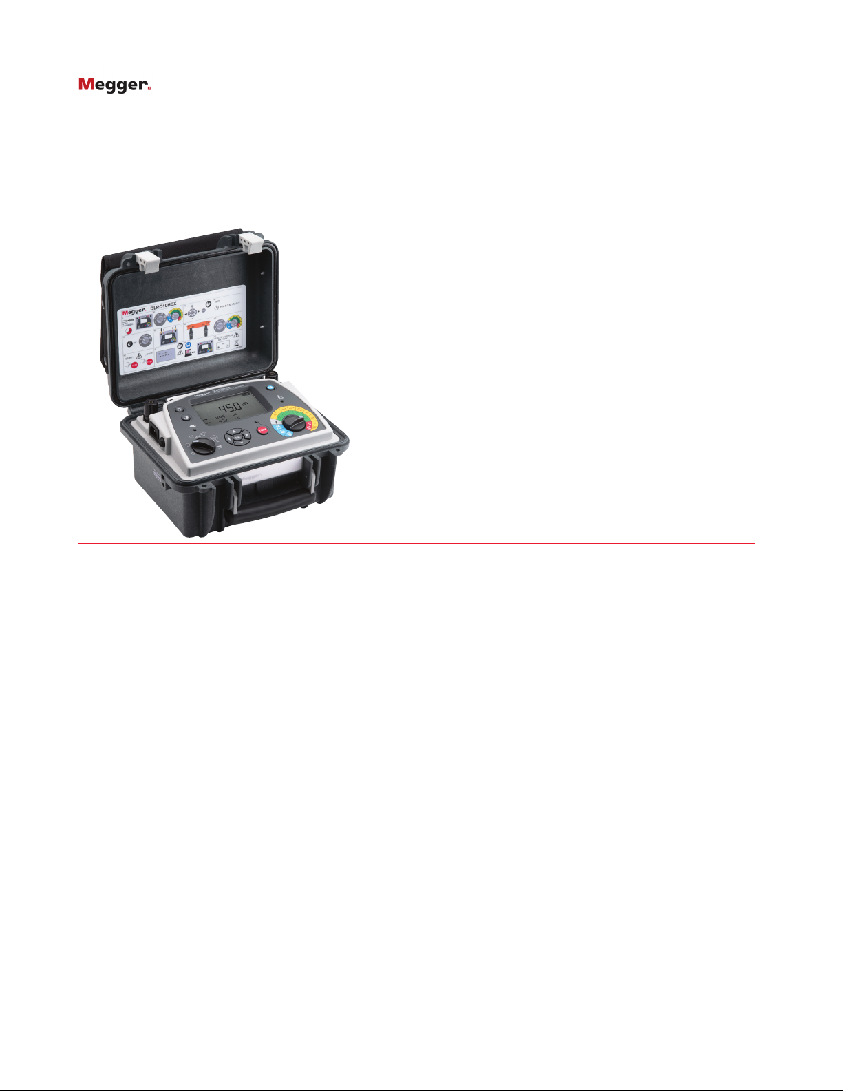
DLRO10HDX
10 Amp Digital Low Resistance
■ NEW Onboard memory storage for test
results up to 200 records (HDX only)
■ Download to PowerDB
■ NEW interchangeable test lead terminations
■ High or low output power selection for
condition diagnosis
■ Operates from battery or AC mains supply
■ Protected to 600 V without blowing a fuse,
test lead live voltage warning light
■ Heavy duty case: IP 65 lid closed,
IP54 operational
DLRO10HDX
DESCRIPTION
Augmenting Megger’s DLRO10 and 10X range the
DLRO10HDX combines ultimate simplicity of operation with
a rugged IP65 case designed for stable ground and bench
operation and provides memory storage.
These units are powered from either rechargeable battery
or AC power making it suitable for continuous testing in
production line/repetitive use environments.
Rotary switch controls are simple and easy to operate in all
weather conditions and with gloved hands. A large, clear,
backlit LCD display is easy to read from a distance. The
DLRO10HDX provides significantly enhanced compliance
and is capable of delivering 10 A into measurements up
to 250 mΩ and 1 A into measurements up to 2.5 Ω. The
duration of each test may be up to 60 seconds.
The DLRO10HDX is rated CAT III 300 V provided the
optional terminal cover is fitted to the instrument. Details can
be found in the ordering information panel of this data sheet.
The DLRO10HDX provides five test modes each of which is
selected through a simple rotary control on the Mode selection
rotary switch. All memory functions, delete, download to
PowerDB and recalling test results are also accessible via the
Range Selection rotary switch.
A simple control panel enables easy navigation for
configuration settings.
■ Simple rotary switch selection of five test
modes, including auto start on connection
History of ‘DUCTER’ Testing
For over 100 years the ‘Ducter’ test has been used to describe
a simple test for measuring ver low contact resistances and
‘Ducter’, which is still used as a trademark, was the name
origianally given to the low resistance ohmmeter manufactured
by Megger. The name ‘Ducter’ was registered by Megger in
June 1908 and ‘Ducter’ has since become the inudstry standard.
FEATURES AND BENEFITS
n Rugged case well suited to transportation with shoulder
strap and lead set pouch
n Removable lid facilitates easy test lead connection
n Operational ingress protection is IP 54 (battery power only)
ensuring protection from the elements
n 7Ah lead acid battery provides extended operation and can
be charged whilst operating from line power
n Rotary mode switch with bidirectional (current reversal with
averaging cancels thermal EMFs), unidirectional, automatic,
continuous and inductive modes
n Large, clear LCD display with backlight and contrast
adjustment
n Auto power off function conserves battery
Page 2
DLRO10HDX
10 A Digital Low Resistance Ohmmeter
APPLICATIONS
The DLRO10HDX measures low resistance values in applications
ranging from railways and aircraft to resistance of components
in industry.
Any metallic joint can be measured but users must be aware
of measurement limitations depending on application. For
example, if a cable manufacturer plans to make resistive
measurements on a thin wire, a low test current should be
selected to prevent heating the wire thereby changing its
resistance.
Measurements on electric motors and generators will
be inductive and require the user to understand the
inductive mode and charging process before a correct result
is achieved.
The DLRO10HDX is well suited to measuring thick conductors,
bonds and quality of welding because of its 10 A range for
resistance values up to 250 mΩ.
Electromagnetic noise induced into the leads can interfere
with a reading. A noise symbol alerts the user and prevents
a measurement when the instrument detects noise above its
threshold.
When dissimilar metals are joined a thermocouple effect is
created. Users should select a bidirectional mode to ensure
cancellation of this effect. The instrument measures with
current flowing in both directions and averages the result.
Normal mode is initiated by pressing the ‘Test’ button after
connecting the test leads to the unit under test. Continuity
of all four connections is checked. Current is applied in both
forward and reverse direction following which measurement
is displayed.
Automatic mode is started as soon as the probes make
contact. Forward and reverse current measurements are made
and the average value is displayed. This mode is ideal when
working with handspikes. Each time the probes are removed
and reconnected to the load a new test will be performed
without the need to press the test button.
TEST modes
Automatic unidirectional mode applies current in one
direction only to speed up the measurement process.
However thermal EMF resulting from dissimilar metal bonds
can cause lower accuracy. Test starts automatically when
probes are connected.
Continuous mode allows repeated measurements to be made
on the same sample. Simply connect the test leads and press
the test button. The measurement is updated every three
seconds until the circuit is broken.
Inductive mode is selected when measuring resistance on, for
example, motors and generators. When measuring inductive
loads it is necessary to wait for the voltage to stabilize as the
inductive element is charged. Test leads are firmly connected
to the device under test and the ‘Test’ button pressed. The
instrument will pass the selected current through the sample
continuously in one direction only and take repetitive readings
that will gradually decrease to the true value as the voltage
stabilizes. The operator decides when the result is stable and
presses the ‘Test’ button to terminate the test.
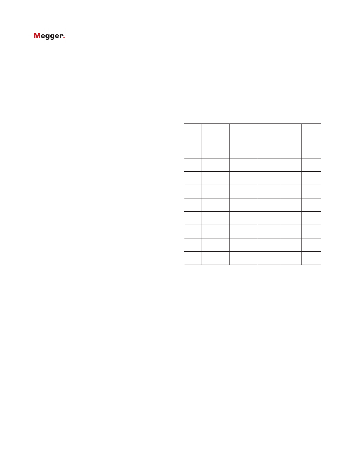
ELECTRICAL SPECIFICATIONS
Resistance/Current Ranges
The green resistance ranges on the keypad indicate low
output power (<0.25 W) outputs. Red ranges indicate higher
2.5 W (1 A) and 25 W (10 A) power outputs.
Resolution and Accuracy
Test current accuracy ±10%
Voltmeter input impedance >200 kΩ
Test
current
Resistance
range
0.1 mA0 to
2500.0 Ω
0.1 mA0 to
250.00 Ω
0 to
1 mA
25.000 Ω
0 to
10 mA
2500.0 mΩ
100 mA0 to
250.00 mΩ
0 to
1 A
25.000 mΩ
0 to
10 A
2500.0 µΩ
0 to
1 A
2500.0 mΩ
0 to
10 A
250.00 mΩ
Resolution
(as
displayed)
0.1 Ω ±0.2% 25 mV
0.01 Ω ±0.2% 25 mV
1 mΩ ±0.2% 25 mV 25 μW
0.1 mΩ ±0.2% 25mV 250 μW
0.01 mΩ ±0.2% 25 mV 2.5 mW
1 μΩ ±0.2% 25 mV 25 mW
0.1 μΩ ±0.2% 25 mV 0.25 W
0.1 mΩ ±0.2% 2.5 V 2.5 W
0.01 mΩ ±0.2% 2.5 V 25 W
Basic
accuracy*
Full
scale
voltage
Max.
power
output
25 μ
W
W
2.5 μ
* The accuracy stated assumes forward and reverse
measurements.
Inductive mode or undirectional mode will introduce an
undefined error if an external EMF is present.
Basic accuracy at reference conditions.
GENERAL SPECIFICATIONS
Temperature coefficient < 0.01% per ºC, from 5 ºC to
40 ºC
Maximum altitude 2000 m (6562 ft) to full safety
specifications
Display size/type Main 5 digit + 2 x 5 digit
secondary displays
Battery type 6 V, 7Ah sealed lead acid
Voltage input range 100 - 240 V 50 / 60 Hz 90 VA
Charge time 8 hours
Backlight LED backlight
Battery life >1000 Auto (3 sec) tests
Page 3

DLRO10HDX
10 A Digital Low Resistance Ohmmeter
Auto power down 300s
Mode selection Rotary switch
Range selection Rotary switch
Memory features selection Rotary switch
Weight 6.7 kg (14.8 lb)
Case dimensions L 315 x W 285 x H 181 mm
(L 12 x W 11 x H 7 in.)
Pouch for test leads Yes (lid mounted)
Test leads included depending on
chosen option:
DH4C lead set
KC1 Kelvin Clip lead set
IP rating IP65 case closed, IP54 battery
operation
Record storage 200 test records
Safety rating
In accordance with IEC61010-1, CATIII 300V when used
with optional terminal cover (details in ordering information)
Operating temperature and humidity
-10 °C to +50 °C
(14 °F to 122 °F) <90% RH
Reference conditions 20 °C ±3 °C (68 °F ±37 °F)
Storage temperature and humidity
-25 °C to +60 °C (-13 °F to +60 °F), <90% RH
EMC
In accordance with IEC61326-1 (Heavy industrial)
Noise rejection
Less than 1% ±20 digits additional error with 100 mV peak
50/60 Hz. on the potential leads. Warning will show if hum
or noise exceeds this level.
Maximum lead resistance
100 mΩ total for 10 A operation irrespective of battery
condition.
OPTIONAL TERMINAL COVER
The CAT III 300 V rating on the
DLRO10HDX is only valid when
the instrument is fitted with
the optional terminal cover to
provide the required creepage
and clearances at the instrument
terminals. Although the terminal
cover may be used with any test
leads, only the Megger DH4,
DH5 and DP1-C duplex handspikes, and KC2-C insulated
kelvin clips have suitable probe insulation to comply with the
requirements of IEC61010-1 and the CATIII 300 V rating.
SUPPLIED LEADSET OPTIONS
DLRO10HDX
+ DH4-C probe 1.5 m leads
+ KC1 Kelvin clip 3 m leads
+ No test leads supplied
Page 4

ORDERING INFORMATION
Item (Qty) Order No.
DLRO10HDX, no leads supplied 1008-052
DLRO10HDX, suplied with hand spikes 1008-075
DLRO10HDX, supplied with Kelvin clips 1008-095
Standard included accessories
Test lead pouch (lid mounted) 1000-036
DLRO10HDX user guide CD
Optional Accessories at extra cost
Calibration Shunt,10 Ω, current rating 1 mA 249000
Calibration Shunt, 1 Ω, current rating 10 mA 249001
Calibration Shunt, 100 mΩ current rating 1A 249002
Calibration Shunt, 10 mΩ current rating 10 A 249003
Certificate of Calibration for Shunts, NIST CERT-NIST
Optional Test Leads at extra cost
Normal test leads not fitted with in-line connector:
Duplex Leads
DH5 straight duplex handspikes (2)
One has indicator lights. 2.5m/8ft 6111-517
Terminal cover (use in conjunction with DH4 test leads
supplied as standard, or optional DH5 test leads for
CATIII 300 V compliance 1002-390
Duplex Handspikes (2) with spring loaded helical contacts
2m/7ft 242011-7
DH1 2.5m/8ft 1006-442
DH1 5.5m/18ft 242011-18
DH2 6m/20ft (only 1 lead supplied) 1006-443
DH2 9m/30ft (only 1 lead supplied) 242011-30
DLRO10HDX
10 A Digital Low Resistance Ohmmeter
Item (Qty) Order No.
Duplex Heavy Duty 5cm (2”) C-Clamps. (2)
2m/7ft 242004-7
Duplex Heavy Duty 5cm (2”) C-Clamps. (2)
5.5m/18ft 242004-18
Duplex Heavy Duty 5cm (2”) C-Clamps. (2)
9m/30ft 242004-30
Duplex handspikes with replaceable
Needle Points 2m/7ft 242003-7
Duplex 1.27 cm (1/2“) Kelvin Clips (2)
gold plated 2m/7ft 241005-7
Duplex 1.27 cm (1/2“) Kelvin Clips (2)
silver plated 2m/7ft 242005-7
Duplex 3.8 cm (11/2”) Kelvin Clips (2)
2m/7ft 242006-7
Duplex 3.8 cm (11/2”) Kelvin Clips (2)
5.5m/18ft 242006-18
Duplex 3.8 cm (11/2”) Kelvin Clips (2)
9m/30ft 242006-30
Single handspike (1) for potential measurement
2m/7ft 242021-7
Single handspike (1) for potential measurement
5.5m/18ft 242021-18
Single handspike (1) for potential measurement
9m/30ft 242021-30
Current clip (1) for current connections
2m/7ft 242041-7
Current clip (1) for current connections
5.5m/18ft 242041-18
Current clip (1) for current connections
9m/30ft 242041-30
6m/20 ft ext 1006-460
Straight Duplex Handspikes (2) Heavy Duty
with fixed contacts. 2m/7ft 242002-7
Straight Duplex Handspikes (2) Heavy Duty
with fixed contacts 5.5m/18ft 242002-18
Straight Duplex Handspikes (2) Heavy Duty
with fixed contacts 9m/30ft 242002-30
SALES OFFICE
Megger USA Valley Forge Corporate Center
2621 Van Buren Avenue, Norristown,
Pennsylvania, 19403, USA
T. 1-610 676 8500
F. 1-610-676-8610
DLRO10HDX_DS_US_V04
www.megger.com
ISO 9001
The word ‘Megger’ is a registered trademark
 Loading...