

Page 1
10 A Digital Low Resistance Ohmmeter
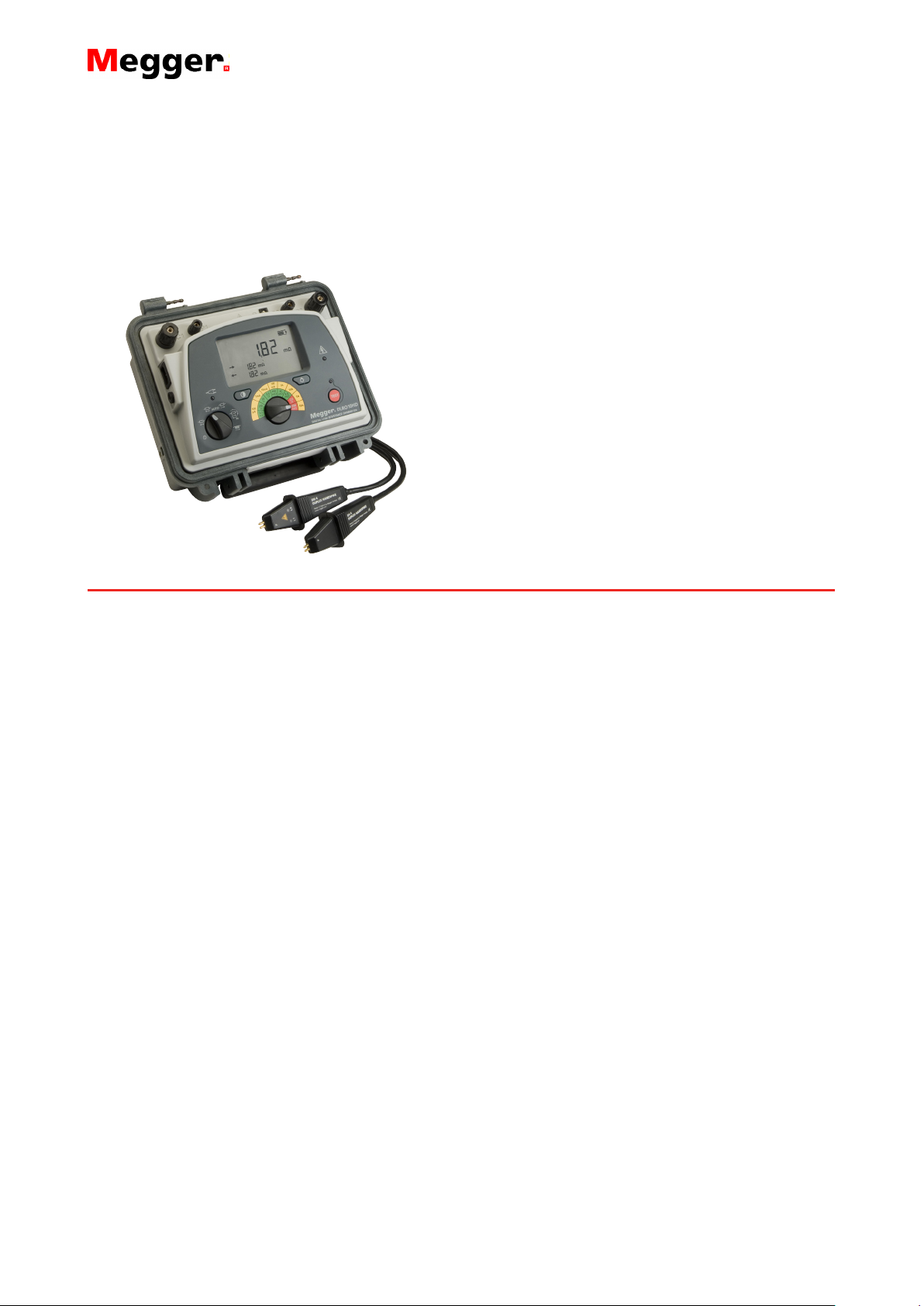
DLRO10HD
10 Amp Digital Low Resistance
n High or low output power selection for
condition diagnosis
n Rechargeable battery or line power supply,
continuous operation, even with dead
battery
n 10 A for 60 seconds, less time waiting to
cool, great for charging inductance
n High input protection to 600 V, inadvertent
connection to line or UPS voltage will not
blow a fuse
n Heavy duty case: IP 65 lid closed, IP54
operational (battery operation only)
n Rotary switch selects one of five test
modes, including auto start on connection,
giving ease of use
DLRO10HD
DESCRIPTION
Augmenting Megger’s DLRO10 and 10X range the
DLRO10HD combines ultimate simplicity of operation with
a rugged IP65 case designed for stable ground and bench
operation.
The unit is powered from either its rechargeable battery or
line power making it suitable for continuous testing in
production line/repetitive use environments.
Rotary switch controls are simple and easy to operate in all
weather conditions and with gloved hands. A large, clear,
backlit LCD display is easy to read from a distance. The
DLRO10HD provides significantly enhanced compliance
and is capable of delivering 10 A into measurements up to
250 mΩ and 1 A into measurements up to 2.5 Ω. The
duration of each test may be up to 60 seconds.
The DLRO10HD is rated CATIII 300 V provided the
optional terminal cover is fitted to the instrument. Details
of which can be found in the ordering information panel of
this data sheet.
The DLRO10HD provides five test modes each of which is
selected through a simple rotary control.
ADDITONAL FEATURES AND BENEFITS
n Rugged case well suited to transportation with shoulder
strap and lead set pouch
n Removable lid facilitates easy test lead connection
n Operational ingress protection is IP 54 (battery power
only) ensuring protection from the elements
n 7Ah lead acid battery provides extended operation and
can be charged whilst operating from line power
n Rotary mode switch with bidirectional (current reversal
with averaging cancels thermal EMFs), unidirectional,
automatic, continuous and inductive modes
n Large, clear LCD display with backlight and contrast
adjustment
n Auto power off function conserves battery
APPLICATIONS
The DLRO10HD measures low resistance values in
applications ranging from railways and aircraft to resistance
of components in industry.
Any metallic joint can be measured but users must be aware
of measurement limitations depending on application. For
example, if a cable manufacturer plans to make resistive
measurements on a thin wire, a low test current should be
selected to prevent heating the wire thereby changing its
resistance.
Measurements on electric motors and generators will
be inductive and require the user to understand the
inductive mode and charging process before a correct result
is achieved.
The DLRO10HD is well suited to measuring thick conductors,
bonds and quality of welding because of its 10 A range for
resistance values up to 250 mΩ.
Electromagnetic noise induced into the leads can interfere
with a reading. A noise symbol alerts the user and prevents
a measurement when the instrument detects noise above its
threshold.
When dissimilar metals are joined a thermocouple effect is
created. Users should select a bidirectional mode to ensure
cancellation of this effect. The instrument measures with
current flowing in both directions and averages the result.
Normal mode is initiated by pressing the ‘Test’ button after
connecting the test leads to the unit under test. Continuity of
all four connections is checked. Current is applied in both
forward and reverse direction following which measurement is displayed.
Page 2

DLRO10HD
10 A Digital Low Resistance Ohmmeter
Automatic mode is started as soon as the probes make
contact. Forward and reverse current measurements are
made and the average value is displayed. This mode is
ideal when working with the supplied DH4 handspikes.
Each time the probes are removed and reconnected to
the load a new test will be performed without the need to
press the test button.
TEST modes
Automatic unidirectional mode applies current in one
direction only to speed up the measurement process.
However thermal EMF resulting from dissimilar metal
bonds can cause lower accuracy. Test starts automatically
when probes are connected.
Continuous mode allows repeated measurements to be
made on the same sample. Simply connect the test leads
and press the test button. The measurement is updated
every three seconds until the circuit is broken.
Inductive mode is selected when measuring resistance
on, for example, motors and generators. When measuring
inductive loads it is necessary to wait for the voltage to
stabilise as the inductive element is charged. Test leads
are firmly connected to the device under test and the
‘Test’ button pressed. The instrument will pass the
selected current through the sample continuously in one
direction only and take repetitive readings that will
gradually decrease to the true value as the voltage
stabilises. The operator decides when the result is stable
and presses the ‘Test’ button to terminate the test.
ELECTRICAL SPECIFICATIONS
Resistance/Current Ranges
The green resistance ranges on the keypad indicate low
output power (<0.25 W) outputs. Red ranges indicate
higher 2.5 W (1 A) and 25 W (10 A) power outputs.
Inductive mode or undirectional mode will introduce an
undefined error if an external EMF is present.
Basic accuracy at reference conditions.
GENERAL SPECIFICATIONS
Temperature coefficient < 0.01% per ºC, from 5 ºC to
40 ºC
Maximum altitude 2000m (6562 ft) to full safety
specifications
Display size/type Main 5 digit + 2 x 5 digit
secondary displays
Battery type 6 V, 7Ah sealed lead acid
Voltage input range 90 - 264 V, 50-60 Hz
Charge time 8 hours
Backlight LED backlight
Battery life >1000 Auto (3 sec) tests
Auto power down 300s
Mode selection Rotary switch
Range selection Rotary switch
Weight 6.7 kg
Case dimensions L315 mm x W285 mm x
H181 mm
Pouch for test leads Yes (lid mounted)
Resolution and Accuracy
Test current accuracy ±10%
Voltmeter input impedance >200 kΩ
Test
current
0.1 mA
0.1 mA
1 mA
10 mA
100 mA
1 A
10 A
1 A
10 A
Resistance
range
0 to
2500.0 Ω
0 to
250.00 Ω
0 to
25.000 Ω
0 to
2500.0 mΩ
0 to
250.00 mΩ
0 to
25.000 mΩ
0 to
2500.0 μΩ
0 to
2500.0 mΩ
0 to
250.00 mΩ
Resolution
(as
displayed)
0.1 Ω ±0.2% 25 mV 25 μW
0.01 Ω ±0.2% 25 mV 2.5 μW
1 mΩ ±0.2% 25 mV 25 μW
0.1 mΩ ±0.2% 25mV 250 μW
0.01 mΩ ±0.2% 25 mV 2.5 mW
1 μΩ ±0.2% 25 mV 25 mW
0.1 μΩ ±0.2% 25 mV 0.25 W
0.1 mΩ ±0.2% 2.5 V 2.5 W
0.01 mΩ ±0.2% 2.5 V 25 W
Basic
accuracy*
Full
scale
voltage
* The accuracy stated assumes forward and reverse
measurements.
Max.
power
output
Test leads DH4 lead set included
IP rating IP65 case closed, IP54 battery
operation
Safety rating
In accordance with IEC61010-1, CATIII 300V when used
with optional terminal cover (details in ordering information)
Operating temperature
and humidity -10 °C to +50 °C
(14 °F to 122 °F) <90% RH
Reference conditions 20 °C ±3 °C
Storage temperature and
humidity -25 °C to +60 °C, <90% RH
EMC
In accordance with IEC61326-1 (Heavy industrial)
Noise rejection
Less than 1% ±20 digits additional error with 100 mV peak
50/60 Hz. on the potential leads. Warning will show if hum
or noise exceeds this level.
Maximum lead resistance
100 mΩ total for 10 A operation irrespective of battery
condition.
Page 3

OPTIONAL TERMINAL COVER
The CATIII 300 V rating on
the DLRO10HD is only valid
when the instrument is fitted
with the optional terminal
cover to provide the required
creepage and clearances at
the instrument terminals.
Although the terminal cover
may be used with any test
leads, only the Megger DH4 and DH5 duplex handspikes
have suitable probe insulation to comply with the
requirements of IEC61010-1 and the CATIII 300 V rating.
ORDERING INFORMATION
Item (Qty) Order No.
DLRO10HD Low Resistance Ohmmeter 1000-348
Included accessories
DH4 duplex handspike 1.2m 6111-503
Test lead pouch (lid mounted) 1000-036
DLRO10HD user guide CD 1000-869
Warranty book. 6170-618
Optional Accessories at extra cost
Calibration Shunt,10 Ω, current rating 1 mA. 249000
Calibration Shunt, 1 Ω, current rating 10 mA. 249001
Calibration Shunt, 100 mΩ current rating 1A. 249002
Calibration Shunt, 10 mΩ current rating 10 A. 249003
Certificate of Calibration for Shunts, NIST CERT-NIST
Replacement tips for DH4 and DH5 handspikes.
Needle point 25940-012
Serrated end 25940-014
Optional Test Leads at extra cost
Duplex Leads
DH5 straight duplex handspikes (2).
One has indicator lights. 2.5m/8ft 6111-517
Terminal cover (use in conjunction with DH4 test leads supplied
as standard, or optional DH5 test leads for CATIII 300 V
compliance) 1002-390
Duplex Handspikes (2) with spring loaded helical contacts.
2m/7ft 242011-7
DH1 2.5m/8ft 6111-022
5.5m/18ft 242011-18
only 1 lead supplied
DH2 6m/20ft 6111-023
9m/30ft 242011-30
DH3 9m/30ft 6111-024
DLRO10HD
10 A Digital Low Resistance Ohmmeter
Item (Qty) Order No.
Straight Duplex Handspikes (2)
Heavy Duty with fixed contacts.
2m/7ft 242002-7
5.5m/18ft 242002-18
9m/30ft 242002-30
Duplex Heavy Duty 5cm (2”)
C-Clamps. (2)
2m/7ft 242004-7
5.5m/18ft 242004-18
9m/30ft 242004-30
Duplex handspikes with replaceable
Needle Points 2m/7ft 242003-7
Duplex 1.27 cm (1/2 “)
Kelvin Clips. (2)
gold plated 2m/7ft 241005-7
silver plated 2m/7ft 242005-7
Duplex 3.8 cm (11/2”)
Kelvin Clips. (2) 2m/7ft 242006-7
5.5m/18ft 242006-18
9m/30ft 242006-30
Single Leads
Single handspike (1) for potential measurement.
2m/7ft 242021-7
5.5m/18ft 242021-18
9m/30ft 242021-30
Current clip (1) for current connections.
2m/7ft 242041-7
5.5m/18ft 242041-18
9m/30ft 242041-30
Note: For more details of optional leadsets see separate test
lead datasheet DLRO_TL_DS_en_V01.pdf
UK
Archcliffe Road Dover
CT17 9EN England
T +44 (0) 1304 502101
F +44 (0) 1304 207342
UKsales@megger.com
UNITED STATES
4271 Bronze Way
Dallas TX 75237-1019 USA
T 800 723 2861 (USA only)
T +1 214 333 3201
F +1 214 331 7399
USsales@megger.com
OTHER TECHNICAL SALES OFFICES
Valley Forge USA, College Station USA, Sydney
AUSTRALIA, Täby SWEDEN, Ontario CANADA,
Trappes FRANCE, Oberursel GERMANY, Aargau
SWITZERLAND, Kingdom of BAHRAIN, Mumbai
INDIA, Johannesburg SOUTH AFRICA, Chonburi
THAILAND, Malaga SPAIN
CERTIFICATION ISO
Registered to ISO 9001:2008 Cert. no. Q 09250
Registered to ISO 14001-2004 Cert. no. EMS 61597
DLRO10HD_DS_EN_V04
www.megger.com
Megger is a registered trademark
 Loading...