

Page 1
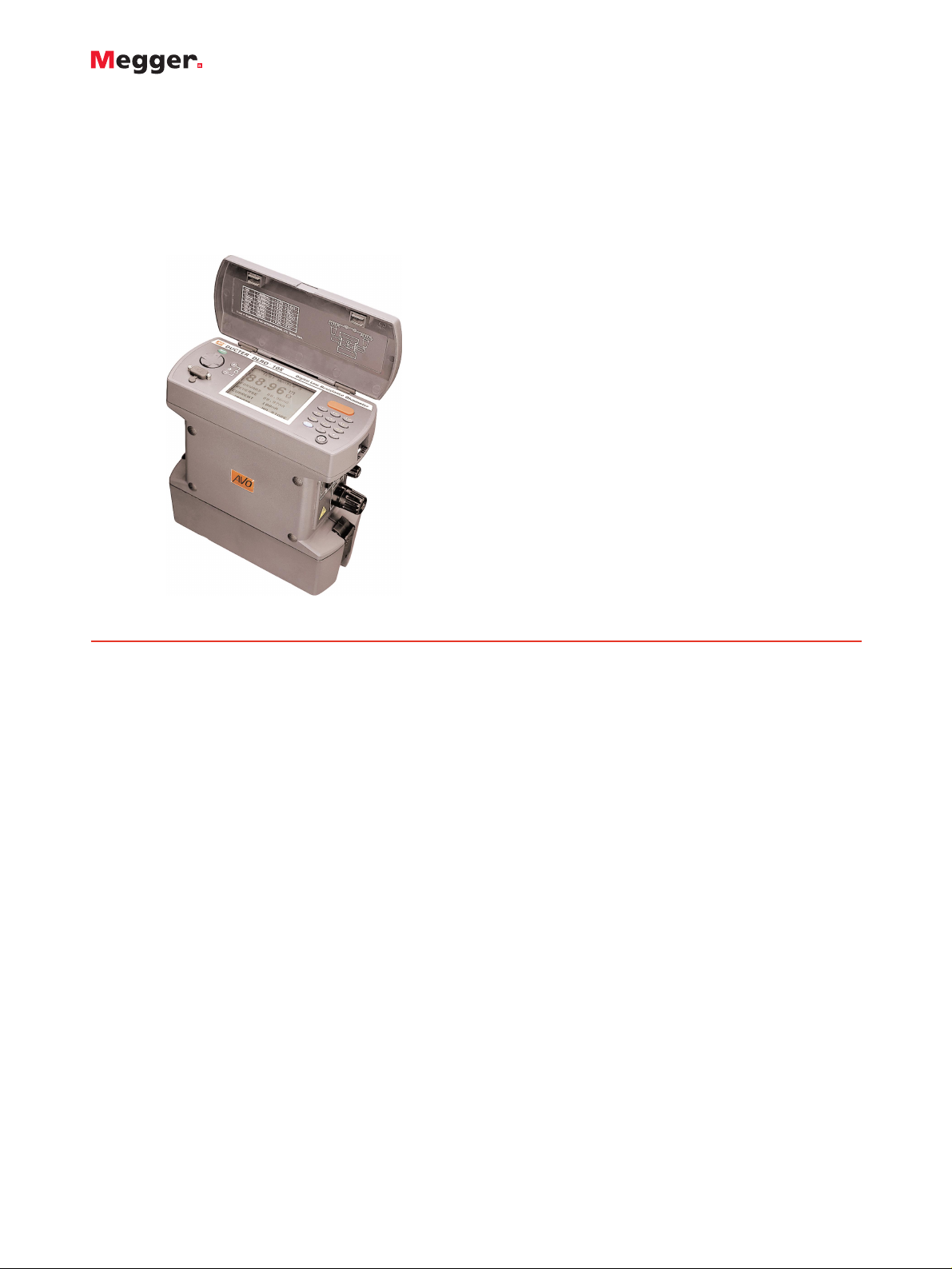
DLRO 10 and DLRO 10X
Digital Microhmmeter
DESCRIPTION
DLRO 10 and DLRO 10X set the standards for low resistance
measurement. DLRO 10 and DLRO 10X are fully automatic
instruments, selecting the most suitable test current up to 10A d.c.
to measure resistance from 0.1 µΩ to 2000 Ω, on one of seven
ranges.
For users who desire more control over the measurement process,
DLRO 10X uses a menu system controlled by a two-axis paddle to
allow the user to manually select the maximum test current.
DLRO 10X also adds real time download of results and on board
storage for later download to a PC.
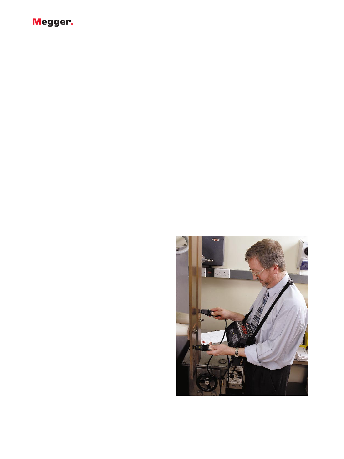
Both instruments are built into a strong, lightweight case that is
equally at home in the field or in the laboratory. Light enough to
be worn around the neck, they are small enough to be taken into
areas that were previously too small to access.
DLRO 10 uses a large, bright 4 1/2 -digit LED display while DLRO
10X has a large, backlit LCD display. Normally, measurements are
made with forward and reverse currents to cancel the effects of
any standing voltages across the test sample.
The average value is then displayed within 3 seconds, to a basic
accuracy of 0.2%. DLRO 10X displays both forward and reverse
measurements as well as the average of the two.
DLRO 10X allows the user to set high and low pass limits, thereby
enabling simple go-no-go testing.
At the end of a test DLRO10X will store the test results, as well as
any notes relevant to the test.
To assist operator safety and ease of use, both instruments are
supplied complete with a pair of duplex handspikes with 1.2 m
(4 ft) leads. One of the probes is fitted with LED’s, which
duplicate indicators on the instrument display indicating that all
four contacts have been made, the presence of a high voltage
across the load, and the presence of current flow while a load is
discharging. A full range of test leads is available with probes,
clamps and Kelvin clips.
Nickel Metal Hydride (NiMH) batteries power the instruments.
The battery packs are interchange-able so that an exhausted
battery may be recharged using the external charger supplied
while testing continues using a spare pack. Although full charging
will take 4 hours, a fast charge mode allows the battery to be 90%
charged within 2 1/2 hours from a 12 volt battery or from a
standard 120/230 V AC supply via the supplied charger. The
battery pack contains its own battery state indicator, which allows
the charge-state to be monitored, even without being connected
to the instrument.
DLRO 10X is fitted with RS232 communications that will allow
results to be downloaded in real time or stored for later retrieval.
Up to 700 sets of results may be stored within DLRO 10X
complete with notes containing up to 200 characters which may
be added using the on board keypad. These results can also be
downloaded to a PC.
MEASUREMENT MODES:
A variety of measurement modes are available. Since the
introduction of V2.0 firmware, Normal, Auto, Continuous and
Inductive mode are available on both the DLRO 10 and the
DLRO 10X.
■
Auto current reversal cancels standing
emfs
■
Protected to 600 V
■
Automatically detects continuity in
potential and current connections
■
Multiple operating modes including fully
automatic
■
Alpha-numeric keypad for entering test
notes (DLRO 10X)
■
User selectable high and low limits
(DLRO 10X)
■
Printer output and memory (DLRO 10X)
DLRO 10 AND DLRO10X
Digital Microhmmeter
Page 2
DLRO 10 AND DLRO 10X
Digital Microhmmeter
FEATURES AND BENEFITS
■ Small, lightweight and portable - can be used in tight places,
reduces the need for extra long leads and two person
operation.
■ Four terminal resistance method shows the true resistance of
the item under test.
■ Bright LED (DLRO 10) and LCD (DLRO 10X) displays are easily
visible under all lighting conditions and reduce human error.
■ Automatically applies forward and reverse currents which cancel
out any standing voltages across the sample under test.
■ Checks for undue noise during measurement, reducing the
possibility of recording the incorrect result.
■ Automatically detects continuity in P and C circuits, preventing
erroneously high reading to be taken due to high resistance
contact.
■ Battery module has a battery condition indicator allowing the
user to check the state of spare batteries without connecting to
the instrument.
■ RS232 connector on the DLRO 10X allows downloading of
results in real time or stored for later retrieval.
DLRO 10 will display the average of the measurements achieved
using forward and reverse current, while DLRO 10X displays both
individual measurements and the average.
Normal mode initiates a test by pressing the Test button on the
instrument front panel after connecting the test leads. Continuity
of all four connections is checked, forward and reverse currents
are applied.
Auto mode allows forward and reverse current measurements to
be made and the average displayed simply by making contact
with all four probes. This mode is ideal when working with the
supplied handspikes. Each time the probes are removed and
reconnected to the load another test will be performed without
the need to press the test button on the instrument.
Continuous mode allows repeated measurements to be made on
the same sample. Simply connect the test leads and press the test
button. The measurement is updated every 3 seconds until the
circuit is broken.
Inductive mode is intended for use when measuring inductive
loads. When measuring inductive loads it is necessary to wait for
the voltage to stabilise. This means that the measurement could
take a few seconds or several minutes. The test leads are firmly
connected to the item to be measured and the Test button is
pressed. The instrument will pass a current through the sample
and wait for the voltage to stabilise. If possible the current will be
increased. This procedure will be repeated until the voltage
detected falls into the range 15 mV to 200 mV. The instrument will
then continue to take readings, which will gradually decrease to
the true value as the voltage stabilises further. The operator
decides when the result is stable and presses the Test button to
terminate the test. Measurement is made with forward current only.
Unidirectional mode, on DLRO 10X only, applies a current in
one direction only. This does not enable any standing emfs to be
negated but speeds up the measurement process. Test starts
automatically when probes are connected.
APPLICATIONS
The needs for accurate low resistance measurement are well
known and very diverse. They range through Goods Receiving
inspection of components to ground bonding and welded joints.
Typical applications include, but are not limited to, making d.c.
resistance measurements of:
■ Switch and contact breaker resistance
■ Busbar and cable joints
■ Aircraft frame bonds and static control circuits
■ Integrity of welded joints
■ Inter-cell connections on battery systems up to 600 V peak
■ Quality control of resistive components
■ Transformer and motor winding resistance
■ Rail and pipe bonds
■ Metal alloys, welds and fuse resistance
■ Graphite electrodes and other composites
■ Wire and cable resistance
■ Transmitter aerial and lightning conductor bonding
The DLROs are light enough to be worn around the neck. They
are also small enough to be taken into areas which were
previously too cramped for easy testing.
Page 3

DLRO 10 AND DLRO 10X
Digital Microhmmeter
Full Scale
1.9999 mΩ
19.999 mΩ
199.99 mΩ
1.9999 Ω
19.999 Ω
199.99 Ω
1999.9 Ω
Resolution
0.1 µΩ
1 µΩ
10 µΩ
100 µΩ
1 mΩ
10 mΩ
100 mΩ
Accuracy
±0.2% ±0.2µΩ
±0.2% ±2 µΩ
±0.2% ±20 µΩ
±0.2% ±0.2 mΩ
±0.2% ±2 mΩ
±0.2% ±20 mΩ
±0.2% ±0.2 Ω
Resistive
20 mV
20 mV
20 mV
20 mV
20 mV
20 mV
200 mV
Inductive
n/a
20 mV
200 mV
200 mV
200 mV
200 mV
200 mV
Resistive
10 A
1 A
100 mA
10 mA
1 mA
100 µA
100 µA
Inductive
n/a
1 A
1 A
100 mA
10 mA
1 mA
100 µA
Full Scale Volts
Test Current
DLRO 10 DLRO 10X
Manual, Auto, Continuous, Manual, Auto, Continuous,
High Power High Power, Unidirectional
Fully Automatic Fully Automatic/Manual
<3s for forward & reverse current and to display average
41/2 digit seven segment LED
LED indication Large backlit LCD
Single cycle reversing d.c. ratiometric measurement -average result display.
±10%
<10 ppm per second
100 mΩ total for 10A operation irrespective of battery condition.
> 200 kΩ
Less than 1% ±20 digits additional error with 100 mV peak 50/60 Hz. on the potential leads. Warning
will show if hum or noise exceeds this level.
Real Time or from storage via RS232
700 tests
Up to 256 characters per test via integral
alphanumeric keypad
7 Ah NiMH rechargeable
Typically 1000 x 10 A tests before recharge
Via External 90V - 260V 50/60 Hz charger or from 12 to 15V d.c. supply
2.5 hours to 90% capacity, 4 hrs for full charge
+5ºC to +45ºC (41ºF to 113ºF) at full specification
-10ºC to +50ºC (14ºF to 122ºF) at reduced accuracy
-30ºC to +70ºC (-22ºF to 158ºF)20ºC (68ºF)
<0.01% per ºC over range 5ºC to 40ºC
<0.01% per ºC from 5ºC to 40ºC (<0.006% per oF from 41ºF to 104ºF)
0ºC to +45ºC (32ºF to 113ºF)
+10ºC to +45ºC (50ºF to 113ºF)
90% RH @ 40ºC (104ºF) non-condensing
2000m (6500 ft) to full safety specifications
In accordance with EN61010-1 600V Category III
The instrument meets EN50081-1 and EN50082-1 (1992)
220 x 100 x 237 mm (8.6 x 4 x 9.5 in)
2.6 kg (5 3/4 lb.) including battery module.
Measurement: Mode:
Control:
Speed:
Display: Measurement:
Range and Safety:
Test Method:
Test Current:
Accuracy:
Stability:
Maximum Lead Resistance:
Voltmeter input impedance:
Hum rejection:
Data:
Transfer:
Storage:
Memo Field
Battery: Capacity:
Life:
Recharge:
Charging Rate: Standard:
Temperature: Operation:
Storage:
Calibration:
Co-efficient:
Slow charging:
Fast charging:
Humidity (max):
Altitude (max):
Safety:
EMC:
Dimensions:
Weight:
Page 4

ORDERING INFORMATION
Item (Qty) Order No.
DLRO 10 Digital Low Resistance Ohmmeter 6111-428
DLRO10X Digital Low Resistance Ohmmeter 6111-429
Complete with
7 Ah NiMH battery module. 6340-101
DH4 Duplex handspikes (2),
one with indicator lights. 1.2m / 4 ft 6111-503
Battery charger for operation from 115/230 V .
50/60Hz supply. 6280-333
Cigar lighter adapter for battery charging. 6280-332
User guide. 6172-473
Warranty book. 6170-618
Optional Accessories at extra cost
Carrying case for DLRO10/10X
and all standard accessories. 6380-138
Carrying case for optional lead sets. 18313
Calibration Shunt,10 Ω, current rating 1 mA. 249000
Calibration Shunt, 1 Ω, current rating 10 mA. 249001
Calibration Shunt, 100 mΩ current rating 1A. 249002
Calibration Shunt, 10 mΩ current rating 10 A. 249003
Certificate of Calibration for Shunts, NIST CERT-NIST
Replacement tips for DH4, DH5 and DH6 handspikes.
Needle point 25940-012
Serrated end 25940-014
Optional Test Leads at extra cost
Duplex Leads
DH5 straight duplex handspikes (2).
One has indicator lights. 2.5m/8ft 6111-517
DH6 Duplex handspikes (2) suitable
for working on 600 V. systems. 2.5m/8ft 6111-518
Duplex Handspikes (2) with spring
loaded helical contacts. 2m/7ft 242011-7
2.5m/8ft 6111-022
5.5m/18ft 242011-18
6m/20ft 6111-023
9m/30ft 242011-30
Item (Qty) Order No.
Straight Duplex Handspikes (2)
Heavy Duty with fixed contacts. 2m/7ft 242002-7
5.5m/18ft 242002-18
9m/30ft 242002-30
Duplex Heavy Duty 5cm (2")
C-Clamps. (2) 2m/7ft 242004-7
5.5m/18ft 242004-18
9m/30ft 242004-30
Duplex handspikes with replaceable
Needle Points 2m/7ft 242003-7
Duplex 1.27 cm (1/2 ")
Kelvin Clips. (2) gold plated 2m/7ft 241005-7
silver plated 2m/7ft 242005-7
Duplex 3.8 cm (11/2")
Kelvin Clips. (2) 2m/7ft 242006-7
5.5m/18ft 242006-18
9m/30ft 242006-30
Single Leads
Single handspike (1) for
potential measurement. 2m/7ft 242021-7
5.5m/18ft 242021-18
9m/30ft 242021-30
Current clip (1) for current
connections. 2m/7ft 242041-7
5.5m/18ft 242041-18
9m/30ft 242041-30
DLRO 10 AND DLRO 10X
Digital Microhmmeter
UK
Archcliffe Road Dover
CT17 9EN England
T +44 (0) 1304 502101
F +44 (0) 1304 207342
UNITED STATES
4271 Bronze Way
Dallas TX 75237-1088 USA
T 800 723 2861 (USA only)
T +1 214 333 3201
F +1 214 331 7399
OTHER TECHNICAL SALES OFFICES
Norristown USA, Toronto CANADA,
Mumbai INDIA, Trappes FRANCE,
Sydney AUSTRALIA, Madrid SPAIN
and the Kingdom of BAHRAIN.
Registered to ISO 9001:2000 Reg no. Q 09290
Registered to ISO 14001 Reg no. EMS 61597
DLR10_DLRO10X_DS_en_V10
www.megger.com
Megger is a registered trademark
 Loading...