

DLRO 10 and DLRO 10X
Digital Microhmmeter
DLRO 10 and DLRO 10X
Digital Microhmmeter
■ NEW interchangeable test lead
terminations
■ Auto current reversal cancels standing
emfs
■ Protected to 600 V
■ Automatically detects continuity in
potential and current connections
■ Multiple operating modes including fully
automatic
■ Alpha-numeric keypad for entering test
notes (DLRO 10X)
DESCRIPTION
DLRO 10 and DLRO 10X set the standards for low resistance
measurement, also known as the Megger ‘Ducter™’ test.
History of ‘Ducter’ testing
For over 100 years the ‘Ducter test’ has been used to describe a
simple test for measuring very low contact resistances and “Ducter”,
which is still used as a trade mark, was the name originally given to
the low resistance ohmmeter manufactured by Megger. The name
Ducter was registered by Megger in June 1908 and ‘Ducter’ has since
become the industry standard.
DLRO 10 and DLRO 10X are fully automatic instruments, selecting the
most suitable test current up to 10 A d.c. to measure resistance from
0.1 μΩ to 2000 Ω, on one of seven ranges.
For users who desire more control over the measurement process,
DLRO 10X uses a menu system controlled by a two-axis paddle to
allow the user to manually select the maximum test current.
DLRO 10X also adds real time download of results and on board
storage for later download to a PC.
Both instruments are built into a strong, lightweight case that is
equally at home in the field or in the laboratory. Light enough to be
worn around the neck, they are small enough to be taken into areas
that were previously too small to access.
DLRO 10 uses a large, bright 4 1/2 -digit LED display while DLRO
10X has a large, backlit LCD display. Normally, measurements are
■ User selectable high and low limits
(DLRO 10X)
■ Printer output and memory (DLRO 10X)
made with forward and reverse currents to cancel the effects of any
standing voltages across the test sample.
The average value is then displayed within 3 seconds, to a basic
accuracy of 0.2%. DLRO 10X displays both forward and reverse
measurements as well as the average of the two.
DLRO 10X allows the user to set high and low pass limits, thereby
enabling simple go-no-go testing.
At the end of a test DLRO10X will store the test results, as well as any
notes relevant to the test.
To ensure customers are able to choose the best test leads to suit
their application, the DLRO10 and DLRO10X may be purchased in
one of two packages. The first option is supplied with a pair of duplex
handspikes with 1.2 m (4 ft) leads, the second option is supplied
without test leads to allow customers to order exactly the test leads
they require from the accessory list.
The instruments are supplied as standard with a Nickel Metal Hydride
(NiMH) battery pack. The battery packs are interchange-able so that
an exhausted battery may be recharged using the external charger
supplied while testing continues using a spare pack. Although full
charging will take 4 hours, a fast charge mode allows the battery
to be 90% charged within 2 1/2 hours from a 12 volt battery or
from a standard 120/230 V AC supply via the supplied charger. The
battery pack contains its own battery state indicator, which allows
the charge-state to be monitored, even without being connected to
the instrument.

DLRO 10 and DLRO 10X
Digital Microhmmeter
In addition an optional mains / line power supply, the DLRO10LPU is
available. This enables the instruments to be directly powered from
90V to 264V, 50/60Hz ideal for repetitive testing applications such as
manufacturing production line use.
DLRO 10X is fitted with RS232 communications that will allow results
to be downloaded in real time or stored for later retrieval.
Up to 700 sets of results may be stored within DLRO 10X complete
with notes containing up to 200 characters which may be added
using the on board keypad. These results can also be downloaded
to a PC.
MEASUREMENT MODES:
A variety of measurement modes are available. Since the introduction
of V2.0 firmware, Normal, Auto, Continuous and Inductive mode are
available on both the DLRO 10 and the DLRO 10X.
DLRO 10 will display the average of the measurements achieved
using forward and reverse current, while DLRO 10X displays both
individual measurements and the average.
Normal mode initiates a test by pressing the Test button on the
instrument front panel after connecting the test leads. Continuity
of all four connections is checked, forward and reverse currents are
applied.
Auto mode allows forward and reverse current measurements to
be made and the average displayed simply by making contact with
all four probes. This mode is ideal when working with the supplied
handspikes. Each time the probes are removed and reconnected to
the load another test will be performed without the need to press the
test button on the instrument.
Continuous mode allows repeated measurements to be made on
the same sample. Simply connect the test leads and press the test
button. The measurement is updated every 3 seconds until the circuit
is broken.
Inductive mode is intended for use when measuring inductive loads.
When measuring inductive loads it is necessary to wait for the voltage
to stabilise. This means that the measurement could take a few
seconds or several minutes. The test leads are firmly connected to the
item to be measured and the Test button is pressed. The instrument
will pass a current through the sample and wait for the voltage to
stabilise. If possible the current will be increased. This procedure will
be repeated until the voltage detected falls into the range 15 mV to
200 mV. The instrument will then continue to take readings, which
will gradually decrease to the true value as the voltage stabilises
further. The operator decides when the result is stable and presses
the test button to terminate the test. Measurement is made with
forward current only.
APPLICATION
The needs for accurate low resistance measurement are well known
and very diverse. They range through Goods Receiving inspection
of components to ground bonding and welded joints. Typical
applications include, but are not limited to, making d.c. resistance
measurements of:
n Switch and contact breaker resistance
n Busbar and cable joints
n Aircraft frame bonds and static control circuits
n Integrity of welded joints
n Inter-cell connections on battery systems up to 600 V
peak
n Quality control of resistive components
n Transformer and motor winding resistance
n Rail and pipe bonds
n Metal alloys, welds and fuse resistance
n Graphite electrodes and other composites
n Wire and cable resistance
n Transmitter aerial and lightning conductor bonding
FEATURES AND BENEFITS
n Small, lightweight and portable - can be used in tight
places, reduces the need for extra long leads and two
person operation.
n Four terminal resistance method shows the true
resistance of the item under test.
n Bright LED (DLRO 10) and LCD (DLRO 10X) displays are
easily visible under all lighting conditions and reduce
human error.
n Automatically applies forward and reverse currents which
cancel out any standing voltages across the sample under
test.
n Checks for undue noise during measurement, reducing
the possibility of recording the incorrect result.
n Automatically detects continuity in P and C circuits,
preventing erroneously high reading to be taken due to
high resistance contact.
Unidirectional mode, on DLRO 10X only, applies a current in one
direction only. This does not enable any standing emfs to be negated
but speeds up the measurement process. Test starts automatically
when probes are connected.
n Battery module has a battery condition indicator allowing
the user to check the state of spare batteries without
connecting to the instrument.
n RS232 connector on the DLRO 10X allows downloading of
results in real time or stored for later retrieval.
2

DLRO 10 and DLRO 10X
Digital Microhmmeter
NEW DUPLEX CONNECT TEST LEADS – NOW
SUPPLIED AS STANDARD
n Carry one lead set and swap terminations
n Simple push and twist for a quick change
n Lockable twist cap secures the leads
n Extension leads available
The Megger DLRO duplex connect four terminal test lead system
is designed to provide the most cost effective and convenient way
to provide the user with all off the test lead terminations and lead
lengths required for the many different applications encountered in
low resistance testing.
At the centre of this unique test lead system is a bespoke connector
allowing terminations such as kelvin clips or duplex test probes to be
changed as required.
SUPPLIED LEADSET OPTIONS:
DLRO10 + NO LEADSET SUPPLIED =
DLRO10-NLS, order code 1006-660
DLRO10 + LEADSET SUPPLIED =
DLRO10 + DH4-C, order code 1006-598
DLRO10X + NO LEADSET SUPPLIED =
DLRO10X-NLS, order code 1006-659
DLRO10X + LEADSET SUPPLIED =
DLRO10X + DH4-C, order code 1006-600
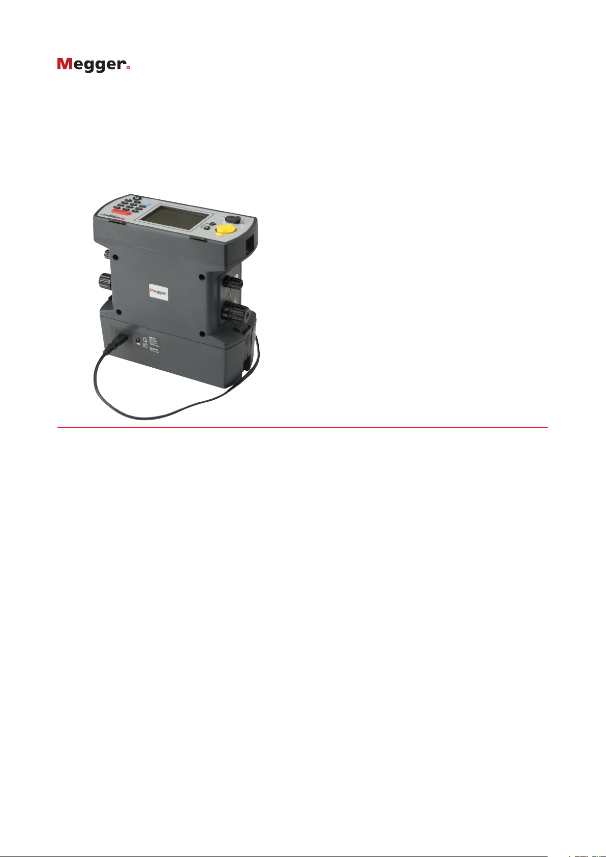
OPTION MAINS / LINE POWER SUPPLY UNIT
The DLRO10 and DLRO10X may
be also powered from an optional
mains / line power supply unit the
DLRO10LPU. This unit is simply
fitted to the instrument in place of
the standard battery pack.
When in use a red LED is illuminated when the instrument is powered
from a mains / line power supply
The DLRO10X is seen here fitted with the optional DLRO10LPU
The DLRO10X will particularly benefit providing the ability to store
test results with memos whilst
powered from a mains / line
supply.
Ideal for repetitive testing
applications such as manufacturing
production line use
Resistance ranges Full scale volts Test current
Full Scale Resolution Accuracy* Resistive Inductive Resistive Inductive
1.9999 mΩ 0.1 μΩ ±0.2% ±0.2 μΩ 20 mV n/a 10 A n/a
19.999 mΩ 1 μΩ ±0.2% ±2 μΩ 20 mV 20 mV 1 A 1A
199.99 mΩ 10 μΩ ±0.2% ±20 μΩ 20 mV 200 mV 100 mA 1 A
1.9999 Ω 100 μΩ ±0.2% ±0.2 mΩ 20 mV 200 mV 10 mA 100 mA
19.999 Ω 1 mΩ ±0.2% ±2 mΩ 20 mV 200 mV 1 mA 10 mA
199.99 Ω 10 mΩ ±0.2% ±20 mΩ 20 mV 200 mV 100 μA 1 mA
1999.9 Ω 100 mΩ ±0.2% ±0.2 Ω 200 mV 200 mV 100 μA 100 μA
3

SPECIFICATIONS
Measurement mode DLRO 10:
Manual, Auto,
Continuous, Inductive
DLRO 10X:
Manual, Auto,
Continuous, Inductive,
Undirectional
Measurement control DLRO 10:
Fully Automatic
DLRO 10X:
Fully Automatic/Manual
Measurement speed <3s for forward and reverse
current and to display average
Display Measurement :
4
Range and safety: DLRO10 LED indications
DLRO10X Large backlight LCD
Test method Single cycle reversing d.c.
ratiometric measurement -
average result display.
Test current accuracy ±10%
Test current stability <10 ppm per second
Lead resistance Maximum
100 mΩ total for 10 A
operation irrespective
of battery condition.
Voltmeter input impedance >200 kΩ
Noise rejection Less than 1% ±20
digits additional
error with 100 mV peak
50/60 Hz.
on the potential leads.
Warning
will show if hum or noise
exceeds this level.
Data transfer DLRO10X:
Real Time or from storage
via RS232
Data storage DLRO10X:
700 tests
Memo field DLRO10X:
Up to 200 characters per
test via
integral alphanumeric keypad
Battery type 7Ah NiMH rechargeable
Battery life Typical 1000 x 10 A
tests before recharge
Battery charge time Via external 90 V - 260 V
50/60 Hz charger from 12 to
15 V dc supply
Standard: 2.5 hours to
90% capacity,
4 hours to fully charged
Slow Charge: +10 °C to
+ 45 °C
(50 °F to 113 °F)
1
/2 digit seven segment LED
Operating temperature range and humidity
+5 °C to +45 °C
(41 °F to 113 °F)
at full accuracy
-10 °C to +50 °C
(14 °F to 122 °F)
at reduced accuracy
<90% RH @ 40 °C (104 °F)
non-condensing
Storage temperature range and humidity
-30 °C to +70 °C
(50 °F to 113 °F)
<90% RH @ 40 °C (104 °F)
non-condensing
Temperature co-efficient <0.01% per °C, over range 5 °C
to 40 °C (<0.0006% per °F
from 41 °F to 104 °F)
Maximum altitude 2000m (6562 ft) to full
safety specifications
Safety In accordance with IEC61010-1,
CAT III 600 V - only when
DH6 leads are used.
EMC IP65 case closed,
IP54 battery operation
In accordance with IEC61326-1
(Heavy industrial)
Dimensions 220 x 100 x 237 mm
Weight 2,6 kg including battery
* The accuracy stated assumes forward and reverse measurements.
Inductive mode or undirectional mode will introduce an undefined
error if an external EMF is present.
DLRO 10 and DLRO 10X
Digital Microhmmeter
4

DLRO 10 and DLRO 10X
Digital Microhmmeter
ORDERING INFORMATION
Description Order Code
DLRO10 + NO LEADSET SUPPLIED =
DLRO10-NLS, 1006-660
DLRO10 + LEADSET SUPPLIED =
DLRO10 + DH4-C, 1006-598
DLRO10X + NO LEADSET SUPPLIED =
DLRO10X-NLS, 1006-659
DLRO10X + LEADSET SUPPLIED =
DLRO10X + DH4-C, 1006-600
Included Accessories
7 Ah NiMH battery module. 6121-492
DH4-C Duplex handspikes (2), one with indicator lights.
1.2m/4 ft (Not NLS models) 1006-444
Battery charger for operation from 115/230 V .
50/60Hz supply. 6280-333
Cigar lighter adapter for battery charging. 6280-332
User guide. 6172-473
Warranty card. 6170-618
Optional Accessories at extra cost
Connect test lead options – see data separate sheet
DLROTestLeads_DS_en_V01
Standard test lead option – see data separate sheet
DLRO_TL_DS_en_V01
Carrying case for DLRO10/10X and
all standard accessories. 6380-138
Carrying bag for cables 18313
Calibration Shunt,10 Ω, current rating 1 mA. 249000
Calibration Shunt, 1 Ω, current rating 10 mA. 249001
Calibration Shunt, 100 mΩ current rating 1A. 249002
Calibration Shunt, 10 mΩ current rating 10 A. 249003
Certificate of Calibration for Shunts, NIST CERT-NIST
DLRO10LPU-EU Mains power attachment -
schuko plug 1003-172
DLRO10LPU-UK Mains power attachment - UK plug 1003-093
DLRO10LPU-US Mains power attachment - US plug 1003-171
Replacement tips for DH4, DH5 and DH6 handspikes.
Needle point 25940-012
Serrated end 25940-014
SALES OFFICE
Megger Limited
Archcliffe Road Dover
CT17 9EN England
T +44 (0) 1304 502101
E UKsales@megger.com
DLRO10--DLRO10X_DS_en_V22
www.megger.com
ISO 9001
The word ‘Megger’ is a registered trademark
 Loading...