

Page 1

WWW.MEGGER.COM
Page 2

Page 3

TABLE OF CONTENTS
Contents
Introduction .......................................................................................................... 2
Clamp-On Testing versus Fall of Potential Testing ............................................. 3
Fall of Potential Testing ................................................................................. 3
Clamp-On Testing ........................................................................................... 4
Clamp-On Ground Testing Theory and Methodology ....................................... 6
Series Circuit ................................................................................................... 6
Parallel Circuit................................................................................................. 7
Parallel-Series Circuit ...................................................................................... 7
Clamp-On Test Methodology ........................................................................ 8
Summary ....................................................................................................... 11
Ground Leakage Current Measurement ........................................................... 11
Applications .................................................................................................. 12
Utility Poles/Service Entrance or Meter .................................................. 12
Street Lighting ......................................................................................... 14
Lightning Protection ................................................................................ 14
Street Cabinets ......................................................................................... 16
Telephone Pedestals ................................................................................ 16
Cell Towers (applications with buried ground ring) .............................. 17
Pad Mounted Transformer ...................................................................... 17
Pole Mounted Transformer ..................................................................... 18
Potential Sources of Error .................................................................................. 19
Factors in Selecting a Clamp-On Ground Tester ............................................... 20
Jaw Design .................................................................................................... 20
Clamp Head Size and Shape ........................................................................ 21
Instrument Size ........................................................................................... 23
Category (CAT) Rating ................................................................................. 24
Noise Filtering............................................................................................... 25
Backlight ....................................................................................................... 25
Data Hold ...................................................................................................... 25
Ergonomics ................................................................................................... 26
Alarm Limit Function.................................................................................... 26
Result Storage............................................................................................... 26
Clamp-on Ground Testers Available from Megger .......................................... 27
Models DET14C/24C...................................................................................... 27
©2013 Megger
Guide to Clamp-on Ground Testing 1
Page 4

Introduction
Testing the quality of the grounding system has been a critical part of any
electrical maintenance program for many years. Ground electrodes are
used to provide a safe path to earth for the dissipation of fault currents,
lightning strikes, static charges and EMF/RFI signals. Over time, ground
systems deteriorate due to either environmental conditions or catastrophic
events (like lightning strikes). Alternatively, facility expansion may change
needs in the installed ground system.
The risks from ground system deterioration include potentially deadly
electrical shocks, plant-wide equipment damage, disruption in the
performance of sensitive electrical equipment, heat build-up and
eventually fire on a single piece of electrical equipment and disruption
in digital communication service. Grounding systems present a unique
challenge because they are out of site, buried beneath the soil. The
only way to ensure that the system remains capable of dissipating fault
currents is to measure its resistance periodically.
Good grounding protects people and equipment and improves the
performance of sensitive electronic equipment. The bonding to the
ground system is also a critical part of the system. Testing the quality
of grounds and bonding should be an active part of any electrical
maintenance strategy. Ground (or earth) testing is done to determine the
effectiveness of the ground system and connections to protect personnel
and equipment and ensure optimal equipment performance. Fall of
potential (and its variants) was the only method of testing ground system
integrity until the 1980s. Clamp-on, or stake-less, ground testing first
appeared in the 1980s and has gained in popularity and acceptance in the
years since its introduction.
This booklet will focus on the clamp-on method of ground testing and
is designed to give the reader a better understanding of the test method
and where it can and cannot be used. Factors that a technician may
want to consider when selecting a clamp-on ground tester will also be
addressed. Please refer to Megger’s booklet “Getting Down to Earth” for
further information on fall of potential tests and soil resistivity tests.
2 1-866-254-0962 www.megger.com
Page 5
Clamp-On Testing versus Fall of Potential Testing
Fall of Potential Testing
As mentioned, clamp-on, or stake-less, ground testing is a relatively
new method of determining the quality of a ground system. The fall of
potential method dates back to the 1930s and is based on the research
of H.B. Dwight. It is the most accurate way of measuring and confirming
ground rod resistance, but it has several major disadvantages. The basic
methodology follows. This booklet will not go into the theory or math
behind this method.
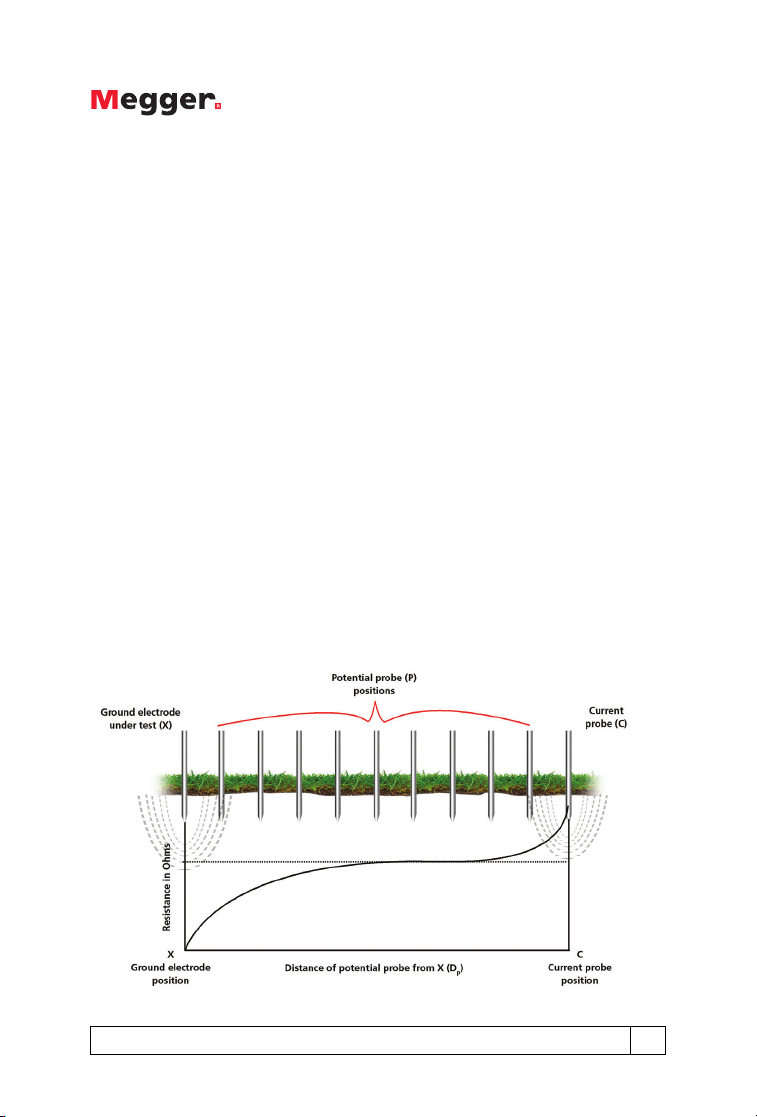
Proper fall of potential testing involves placing a current probe in the soil
at a distance from the ground electrode being tested (please note that
the ground electrode must be disconnected from the system). The actual
distance is determined by the size of the ground electrode/system. The
ground tester is then connected to the ground electrode under test, the
current probe and a potential probe. The potential probe is placed in the
soil at distances of 10%, 20%, 30%, up to 90% of the distance between
the ground electrode and the current probe and a reading is taken at
each location. The readings are then plotted against the distances and the
point where the curve flattens is the approximate resistance of the ground
electrode (see figure below).
Guide to Clamp-on Ground Testing 3
Page 6

The fall of potential method is extremely reliable, as the results can be
checked by testing at different current probe distances. This built-in proof
capability means that results do not have to be accepted on faith. The
operator has complete control of the test set-up. This method can be
used on any size ground system as long as the current probe can be
placed far enough from the ground system under test. It conforms to IEEE
81 and is IEEE approved. In an ideal world, fall of potential would be the
only method used. Unfortunately, nothing is ideal and this method has
three important disadvantages:
1. It is exceedingly time consuming and labor intensive. Temporary probes
must be placed and moved. Cables must be run. Readings must be
taken and plotted.
2. The operator must disconnect the ground electrode to make the test.
As a result, the system is not protected during the test. The ground
electrode must then be reconnected after the test, which, in addition
to being time consuming, leaves the possibility for error if it is poorly
bonded.
3. In real-world situations, space constraints can make it difficult to place
the remote probes.
Clamp-On Testing
The clamp-on ground tester is an effective and time-saving method when
used correctly because the user does not have to disconnect the ground
system to make a measurement or place probes in the ground. The theory
behind this method and the methodology itself will be covered in more
detail later in this booklet. The method is based on Ohm’s Law, where
R (resistance) = V (voltage) / I (current). The clamp includes a transmit coil,
which applies the voltage and a receive coil, which measures the current.
The instrument applies a known voltage to a complete circuit, measures
the resulting current flow and calculates the resistance (see figure on next
page).
4 1-866-254-0962 www.megger.com
Page 7
The clamp-on method requires a complete electrical circuit to measure.
The operator has no probes and therefore cannot set up the desired test
circuit. The operator must be certain that earth is included in the return
loop. The clamp-on tester measures the complete resistance of the path
(loop) that the signal is taking. All elements of the loop are measured in
series. The method assumes that only the resistance of the ground
electrode under test contributes significantly. Based on the math behind
the method (to be reviewed later), the more returns, the smaller the
contribution of extraneous elements to the reading and, therefore, the
greater the accuracy.
The major advantage of the clamp-on method is that it is quick and
easy. The ground electrode does not have to be disconnected from the
system to take the measurement and no probes need to be driven and
no cables connected. In addition, it includes the bonding and overall
connection resistance. Good grounding must be complemented by
“bonding”, having a continuous low-impedance path to ground. Fall of
potential measures only the ground electrode, not the bonding (leads
must be shifted to make a bonding test). Because the clamp-on uses the
grounding conductor as part of the return, an “open” or high resistance
bond will show up in the reading. The clamp-on ground tester also allows
Guide to Clamp-on Ground Testing 5
Page 8
the operator to measure the leakage current flowing through the system.
If an electrode has to be disconnected, the instrument will show whether
current is flowing to indicate whether it is safe to proceed.
Unfortunately, the clamp-on ground tester is often misused in applications
where it will not give an effective reading. The clamp-on method is
effective only in situations where there are multiple grounds in parallel. It
cannot be used on isolated grounds as there is no return path. Therefore,
it cannot be used for installation checks or commissioning new sites.
It also cannot be used if an alternate lower resistance return exists not
involving the soil (such as with cell towers). Unlike with fall of potential
testing, there is no way of proofing the result, meaning the results must
be taken on “faith.” The clamp-on ground tester does fill a role as one
tool that the technician could have in his “bag”, but not the only tool.
Clamp-On Ground Testing Theory and Methodology
Understanding how and why the clamp-on method works helps in
understanding where it will and will not operate, and how to optimize its
use. As mentioned, the clamp-on test method is based on Ohm’s Law
(R = V/I). Understanding Ohm’s law and how it applies to series and
parallel circuits is the first step to understanding how and why a clamp-on
ground tester works. The following graphics will show a series circuit, a
parallel circuit and a series-parallel circuit, and the math used to determine
the total current and resistance.
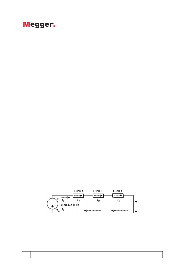
Series Circuit
In a series circuit, total current and total resistance are calculated as
follows: It = I1 = I2 = I
Rt = R1 + R2 + R
6 1-866-254-0962 www.megger.com
3
3
Page 9
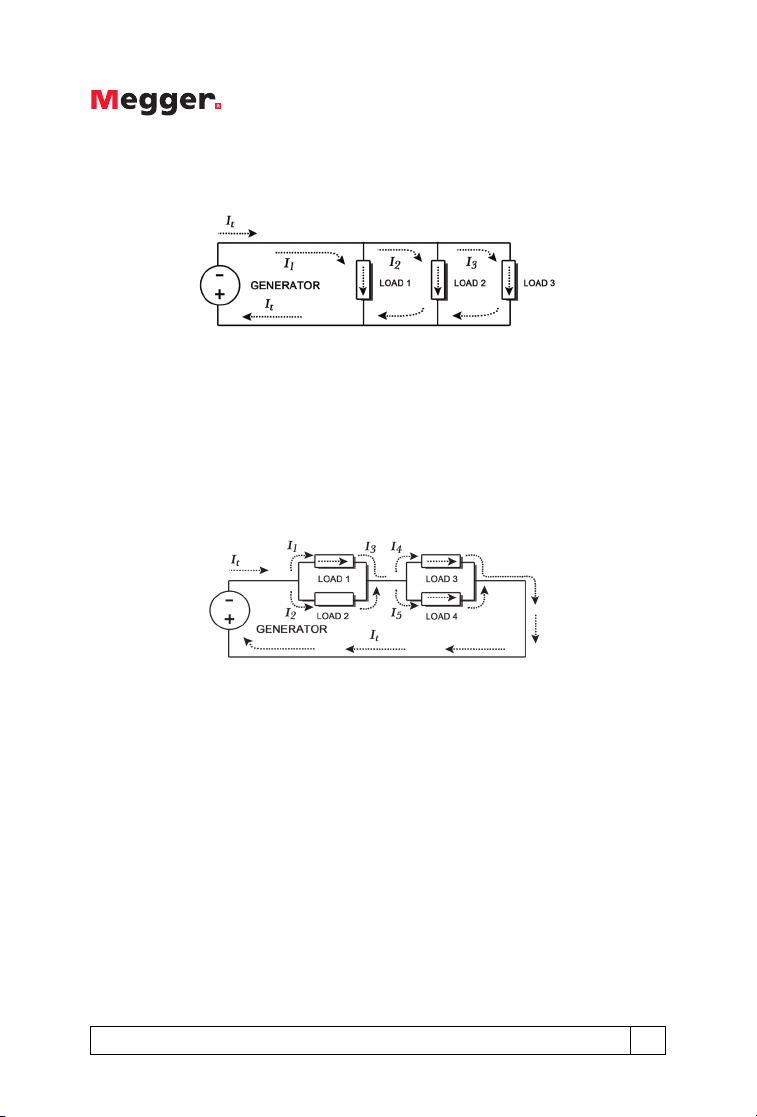
Parallel Circuit
In a parallel circuit, total current and total resistance are calculated as
follows:
It = I1 + I2 + I
3
Rt = 1/ (1/R1 + 1/R2 + 1/R3)
Parallel-Series Circuit
In a parallel-series circuit, total current and total resistance are calculated
as follows:
It = I1 + I2 = I3 = I4 + I
5
Rt = 1/ (1/R1 + 1/R2) + 1/ (1/R3 + 1/R4)
Guide to Clamp-on Ground Testing 7
Page 10
Clamp-On Test Methodology
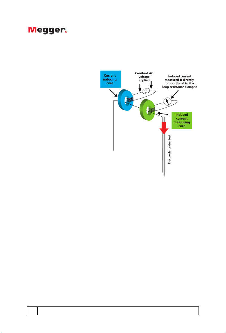
The head of a clamp-on
ground tester includes two
cores (see figure at right). One
core induces a test current
and the other measures how
much was induced. The input
or primary voltage of the
test current inducing core is
kept constant, so the current
actually induced into the test
circuit is directly proportional
to the loop resistance.
The important thing to
remember with clamp-on
testing is that clamp-on
ground testers effectively
make loop resistance
measurements. Clamp-on
measurements are loop
measurements. For the clamp-on method to work there must be a seriesparallel resistance path (and the lower the better). The more electrodes or
ground paths in the system the nearer the measurement gets to the actual
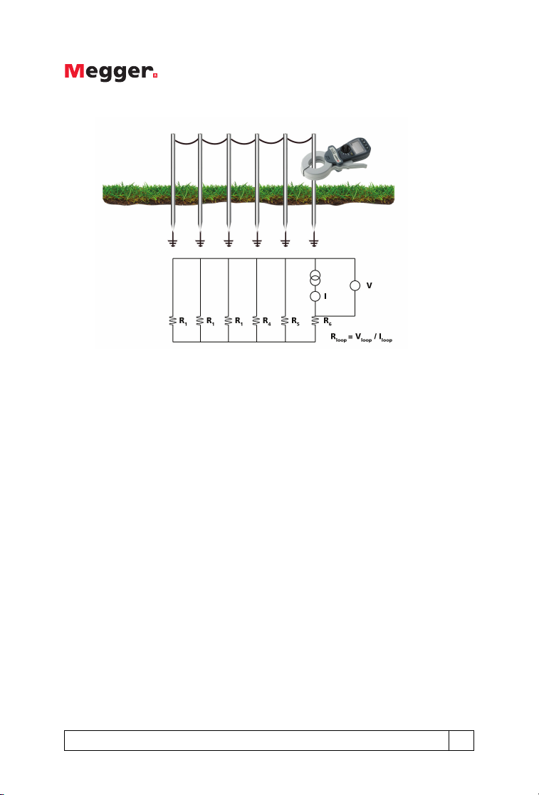
electrode under test’s true resistance. The following figure shows a pole
ground configuration, one of the most effective applications of the clampon ground tester.
8 1-866-254-0962 www.megger.com
Page 11

The circuit diagram for this configuration follows (based on a clamp-on
ground tester being clamped around pole 6):
The clamp-on ground tester is clamped around one of the electrodes and
then measures the resistance of the entire loop. The remaining ground
electrodes are all in parallel, and, as a group, are in series with the ground
electrode being measured. If the clamp-on tester is clamped around
pole #6, the measurement of the resistance of the entire loop would be
calculated using the following equation:
R
= R6 + (1/ (1/R1 + 1/R2 + 1/R3 + 1/R4 + 1/R5))
loop
Guide to Clamp-on Ground Testing 9
Page 12

For six similar ground electrodes with a resistance of 10Ω each, the
measurement of the total loop resistance would be:
R
= 10 + (1/ (1/10 + 1/10 + 1/10 + 1/10 + 1/10))
loop
R
= 10 + (1/ (5/10))
loop
R
= 10 + 2
loop
R
= 12Ω
loop
The measurement of the loop resistance is relatively close to the resistance
of the ground electrode being tested. If there were 60 similar ground
electrodes with a resistance of 10Ω each, the measurement of the total
loop resistance would be:
R
= 10Ω + 0.17Ω = 10.17Ω
loop
The more ground electrodes in parallel, the smaller the impact of the
resistance of the electrodes not being tested and the closer the loop
resistance is to the resistance of the electrode being tested. If the
electrode being measured has a high resistance, the test will indicate that
there is a problem. Using the six electrode example, if electrode number
6 had a resistance of 100Ω and all the other electrodes had resistances of
10Ω, the measurement of the loop resistance would be:
R
= 100 + (1/ (1/10 + 1/10 + 1/10 + 1/10 + 1/10))
loop
R
= 100 + (1/ (5/10))
loop
R
= 100 + 2
loop
R
= 102Ω
loop
In the following example, the clamp-on ground tester would indicate the
bad ground. If the 100Ω electrode was one of the electrodes not being
measured, the impact on the overall measurement would be minimal:
10 1-866-254-0962 www.megger.com
Page 13

R
= 10 + (1/ (1/10 + 1/100 + 1/10 + 1/10 + 1/10))
loop
R
= 10 + (1/ (41/100))
loop
R
= 10 + 2.44
loop
R
= 12.44Ω
loop
Please note that the measured resistance will always be higher than the
actual resistance of the ground electrode being tested. Any error present
is on the side of safety, as resistance guidelines are for maximum ground
resistance. This means that if the measured resistance is below target
level for the ground electrode, the operator can be assured that actual
resistance will also be below the target.
Summary
In summary, remember that a clamp-on ground tester measurement is a
measurement of the resistance of the entire loop. There must be a loop
resistance to measure. If there isn’t a loop to measure the operator can
create one with a temporary jumper lead. The greater the number of
parallel paths, the closer the measured value will be to the actual earth
resistance of the electrode under test. The clamp-on ground tester can
easily indicate a poor electrode whether there are a few parallel paths in
series with the measured value, or many parallel paths present.
Remember that the earth path must be in the circuit to measure ground
resistance. This caveat sounds obvious, but if you have metal structures
involved there may be a connection through that, rather than the earth
mass.
Ground Leakage Current Measurement
In addition to measuring the loop resistance, a clamp-on ground tester
should also have the ability to measure ground leakage current. Operator
safety is the most important reason to measure leakage current. If the
tester indicates leakage current, the operator knows that the circuit is live
and that he/she should not contact it without the proper precautions.
Beyond the safety aspect, the leakage current measurement can indicate
if there is a load imbalance on the system. If the loads are balanced,
Guide to Clamp-on Ground Testing 11
Page 14

there will not be any current flowing. If a 3-phase system has been split
and different pieces of equipment are being run off different phases,
there is the potential for an imbalance. The system will try to compensate
and dump the imbalance on the ground system. This situation results in
wasting energy (and money) and stressing the ground system. Leakage
current flow may also result from gradually deteriorating insulation that is
not bad enough to trip the breaker. Whatever the cause, the presence of
leakage current indicates that further action should be taken.
Applications
As with any type of testing, it is critical that the operator understand
the apparatus (in this case, the ground system) that is being tested. The
clamp-on measurement works in many situations, but is not applicable
in certain configurations. In this section, we will look at various types of
applications and outline whether the clamp-on method is viable or not.
Utility Poles/Service Entrance or Meter
The more parallel earths in series with the electrode under test, the nearer
the measurement will be to the actual earth resistance value. Utility poles
(see below) are an ideal application for the clamp-on method.
12 1-866-254-0962 www.megger.com
Page 15

The earth systems on utility poles have many parallel ground connections
making this a perfect location for using the clamp-on method. Each
pole has a ground electrode to maintain fault and lightning protection,
and pole mounted transformers have two electrodes on star configured
systems. It is important that these electrodes are checked. The overall
earth value of such systems typically needs to be less than 0.3 – 0.5Ω,
while each electrode typically needs to be below 10 – 20Ω to be effective.
Another related application is to test the ground electrode resistance on a
service entrance or meter (see graphic below). Here, there is the possibility
of multiple earth paths, two electrodes, or maybe connection to a water
pipe, so take care to identify the best positions to make a measurement.
Sometimes it is best to clamp the electrode itself below where the earth
connections are made.
Guide to Clamp-on Ground Testing 13
Page 16

Street Lighting
A similar application to utility pole electrodes is street lighting. The cable
running to each street light’s electrode may be clamped, but remember to
clamp the correct side of the grounding conductor as shown below.
Lightning Protection
Another ideal application for the clamp-on test method is to test ground
electrodes on lightning protection. Lightning protection on any building
is only as effective as the quality of its grounding. Electrodes are normally
placed at each corner of a building with extra electrodes between on
larger buildings. The conductors used are typically copper tapes up to 50
mm wide. The following figure shows a typical lightning protection circuit
where a clamp-on ground tester is clamped around the electrode.
14 1-866-254-0962 www.megger.com
Page 17

In many cases this is difficult because the electrode is buried in a small pit.
In addition, many lightning protection down tapes are fitted with
removable links to allow the application of a two-wire continuity test.
These removable links, often referred to as ‘jug handles’, are time
consuming to remove, but make ideal locations to use a clamp-on tester.
The clamp-on tester will measure the whole loop, including all of the
connections and tape bonds, just the same as a two wire test.
Many lightning protection systems on factory buildings, especially in
European countries, use lightning receptors mounted at regular intervals
on the roof. These receptors are all interconnected as shown in the
following figure. This approach further decreases the series resistance of
the parallel earth path, meaning the measured value is even closer to the
true earth resistance of an electrode under test.
Remember there could be other connections to the lightning protection
system. The user must remember to clamp around the tape below all
connections. Otherwise the ground electrode will be tested in parallel
to any other paths to earth. There may be connections to external
metal work such as metal balconies and hand rails. These must also
be above the point where the clamp-on tester is clamped. Remember
the importance of a visual inspection as well. With the price of copper,
grounding tapes can be cut and stolen. Depending where the tape is cut,
and how the system is linked, the instrument could return a good, but
false, reading.
Guide to Clamp-on Ground Testing 15
Page 18

Street Cabinets
Another application is to test the
ground electrode installed inside
primary cross-connection points,
sometime called street cabinet/
flexibility points (see figure below).
These electrodes typically need to be
below 25Ω to maintain reliability. In
this application there may not be more
than two parallel earth paths in series
with the electrode. However, based
on the math, if the clamp-on ground
tester provides a measurement below
25Ω, then the electrode must certainly
be below 25Ω.
Telephone Pedestals
Telephone pedestal ground
electrodes can be tested
using the clamp-on method.
Cable sheaths are all
connected to a ground bar,
which in turn is connected
to the ground electrode.
The clamp-on can be placed
around the cable connecting
the ground bar to the
electrode to perform a test. If
access is difficult a temporary
extension cable can be fitted
to facilitate fitting on the
clamp-on tester.
16 1-866-254-0962 www.megger.com
Page 19

Cell Towers (applications with buried ground ring)
A ground resistance measurement cannot be made if the rods are
linked together by a ring that is buried beneath the soil. This type of
configuration, which is common in cell towers, allows access somewhere
above the ring. Cell towers are grounded at the base, with each guy wire
grounded and all of them connected together in a ring of grounds.
If the operator clamps around the head of one of the guy wire grounds,
the test current will simply complete the circuit in the ground ring and not
through the soil. The test current circulates through the conductor that
connects the individual elements (ground rods) that comprise the ring. As
such, the clamp-on ground tester will not be measuring the quality of the
ground system. The reading will actually be a reading of the resistance
of the “loop”. This measurement does allow the operator to verify the
connections beneath the soil.
Guide to Clamp-on Ground Testing 17
Page 20

Pad Mounted Transformer
Pad-mounted transformer ground electrodes can be verified using
the clamp-on method. However, sometimes there are a number of
connections to the same electrode so the user may have to clamp around
the electrode itself below the connections. Should all these connections
be to a large buried ground mat this measurement would then become
a continuity measurement because the test loop will not include an earth
path.
Pole Mounted Transformer
Remember the first of the two golden
rules of clamp-on testing, “there must
be a loop resistance to measure.”
There are some occasions with utility
poles where that loop does not exist,
at least not where you want it to be
anyway. The figure below illustrates a
system with a star-delta transformer
mounted on a pole with two sets of
electrodes.
Neither set of electrodes are connected
to an overhead earth cable. One
is connected to the metal case of
18 1-866-254-0962 www.megger.com
Page 21

the transformer, and the other is connected to the star point of the LV
secondary winding. The danger here is that the loop measured could
be between the two sets of electrodes, with part of the loop being the
resistance of the wood pole, resulting in a high measurement. This could
mislead the user into believing there is a problem when in fact there isn’t
one.
In contrast, in the graphic below, there is a connection to local distribution
and its local ground system. This means we now have an earth loop to
measure and a measurement may be taken. However, remember the
resistance measurement taken is a combination of the two earths in
series. A measurement of 40Ω will not mean each electrode system is
below 25Ω of course, one could be 10Ω and the other 30Ω. If the
measurement is, for example, 10Ω then we know we are going to be
okay.
Potential Sources of Error
If used correctly, the clamp-on test will give reliable measurements as long
as the operator uses a good quality instrument. To highlight and forewarn
users here are some potential sources of error:
Guide to Clamp-on Ground Testing 19
Page 22

We have already discussed one potential source of error; that the user
might not understand the circuit under test. Remember that there must
be a loop resistance to measure and that the earth path must be in the
circuit to measure earth resistance. The example with the pole-mounted
transformer discussed previously is a prime example of an application
where the earth path was not in the circuit.
There are two other key sources of error that the user must understand:
1. Dirt Trapped in the Clamp Head: Dirt trapped between the closing
gap in the head will modify the magnetic circuit. Magnetic flux will
bleed over between the inducing core and the measuring core. The
result will be a false low reading which in some cases could result in
a poor electrode being measured as being good. Many instruments
use interlocking laminations or teeth as they are sometimes referred
to. These can trap the dirt and are difficult to clean. They are also
easily damaged. Damaged teeth will either result in poor, inaccurate
measurements, or render the instrument useless.
2. Noise Current Affecting the Measurement: Testing in noisy
environments can result in high levels of noise current flowing down
the electrode under test. This can cause readings to vary, making them
difficult to interpret, or if the current is too high, make measurement
impossible.
Factors in Selecting a Clamp-On Ground Tester
The most common reason for users not being able to use the clamp-on
ground tester is poor access. Often cable or tape sizes are too large for
the clamp or the instrument design and size make it difficult to fit in tight
spaces. This section will cover the factors that a user should consider
before buying a clamp-on ground tester. In addition to access, we will
look at safety and performance factors.
Jaw Design
There are two ways to design the jaws of the clamp on a clamp-on
ground tester. The easier way to get the jaws to mate properly is to use
interlocking teeth on the core ends. The more complex way, from an
20 1-866-254-0962 www.megger.com
Page 23

engineering standpoint, is to use flat core ends. This latter approach,
when implemented, provides greater measurement integrity and
instrument reliability.
Interlocking teeth Flat jaws
As mentioned in the section on potential sources of error on the previous
page, dirt trapped between the closing gap in the clamp head can result
in erroneous readings. Clamp-on ground testers are used outdoors in
environments that are often dusty and dirty. They are exposed to materials
that can end up on the core ends of the jaws. With flat core ends, the
surfaces can be cleaned easily. This same material tends to get stuck in the
interlocking teeth and is very hard to remove.
The interlocking teeth are also delicate and relatively easy to damage
or shift out of alignment. Damaged teeth cause the instrument to give
inaccurate readings or can cause the instrument to not work at all. Often,
an instrument with damaged teeth must be scrapped.
When considering a clamp-on ground tester, make sure to look at the
clamp head and jaw mating surfaces.
Clamp Head Size and Shape
Ground electrodes come in different shapes and sizes and can be
positioned in difficult-to-access locations. The clamp head size and shape
should be considered when choosing an instrument. Clamp-on ground
testers have different head shapes (round, oval or elliptical), opening sizes
and thicknesses.
Guide to Clamp-on Ground Testing 21
Page 24

An elliptical shaped head can allow much easier access to ground
electrodes in recessed wells.
A larger inner area allows for clamping around larger ground rods or
ground tapes (some of which can have a width of 50 mm). With a smaller
internal opening on the instrument, the larger ground tape must be cut
and a thinner copper bar welded in between to allow the instrument to
make a measurement.
22 1-866-254-0962 www.megger.com
Page 25

Some ground electrodes are secured quite close to the building wall or
utility pole, making it difficult to clamp the head around the rod. The
thicker the head, the more difficult this process is. A thinner head is
preferable, if performance is not compromised.
Before selecting an instrument, the user should consider the size
and location of the ground electrodes to be tested and compare this
information with the specifications of the instruments being considered.
If the user is unsure of what future requirements might be, he/she should
err on the side of there being larger ground rods/tapes to test in the
future.
Instrument Size
The early clamp-on ground tester
models were quite long. In recent years,
technology has allowed manufacturers to
make these instruments shorter. Why is
shorter better? A shorter instrument will
allow better access in difficult locations,
especially in recessed wells.
Guide to Clamp-on Ground Testing 23
Page 26

Category (CAT) Rating
The CAT rating of a test instrument defines where in the electrical supply
chain the instrument can be safely used. This is usually printed on the
instrument across the test connections and appears as CATII, CATIII or
CATIV. CATI is generally no longer used as it has no practical application.
The CAT rating defines the level of transient (spike or surge) the
instrument has been designed to withstand. These transients vary in size
and duration depending on the source of the transient. The transient
riding on a high-energy supply is more dangerous than a transient on an
isolated cable as it can deliver larger currents when a fault occurs (a spike
on steroids, for example).
A transient may be several kV in amplitude but its duration is typically
very short, maybe only 50 microseconds. On its own the transient will
cause little damage. However, when it occurs on top of the normal
mains sinusoidal supply voltage it can start an arc, which continues until
the end of the cycle. In the case of a CAT IV system the available short
circuit current can be in excess of 1000 amps. This generates hundreds
of kilowatts of heat in a small space for a few milliseconds, creating a big
bang, possibly causing burns, fire or explosion.
Instruments designed with the correct category rating have sufficient
clearance between critical parts to prevent an arc from creating the initial
breakdown when a transient occurs. The electrical supply can be broken
down into categories from CATI to CATIV as shown below:
24 1-866-254-0962 www.megger.com
Page 27

As most ground electrode testing takes place outside, users should
consider buying an instrument rated to CATIV 600 V.
Noise Filtering
As mentioned, testing in electrically noisy environments can result in
high levels of electrical noise current flowing down the electrode under
test. This situation can cause the readings to vary, making them difficult
to read. If the current is too high, it can make measurement impossible.
If the user is going to measure ground resistance in an electrically noisy
environment like a switch yard, he/she should look at clamp-on ground
testers that include noise filtering functions. The instrument should detect
the presence of noise and indicate it to the user. Noise filtering increases
noise immunity (usually with a slight increase in measurement time).
Backlight
Ground tests are not always made in the sunlight or in clear weather. As
an example, measurements are often made in low light environments like
cable basements. If the user may be working in such an environment, he/
she should consider an instrument that includes backlight capability.
Data Hold
Depending on the location of the ground electrode, the instrument’s
screen may not always be visible when taking a reading. In this situation,
the user cannot see the reading being taken by the instrument. Including
a hold function on the instrument allows the user to freeze the reading
and then view it when the screen is again visible. Accessing a data hold
button can be difficult during a test and activating it at the time that
the reading settles requires guesswork. Instruments with intelligent data
hold capability allow the user to activate the data hold function before
clamping around the ground electrode. The unit then automatically
captures the reading once it settles and indicates that the measurement is
done by an audible sound.
Guide to Clamp-on Ground Testing 25
Page 28

Ergonomics
Clamp-on ground testers can be used to make many
measurements in a single day (think about the pole
ground application). It is important to consider the
instrument’s ergonomic features, especially in relation to
opening the jaw. The trigger design should be easy and
comfortable to operate. If it is too small, it will require
more force to open (as there is less leverage) and have a
greater chance of the fingers slipping off, causing the jaw
to snap shut.
Alarm Limit Function
The ability to set audible and visual alarm limits can be quite useful,
especially for inexperienced users. Limit alarms should be able to be set for
both resistance and current. A current alarm is an operator safety feature.
Result Storage
Result storage is another capability that the user should consider before
buying an instrument. Traditionally, ground tester results are written
down manually. Buying an instrument that stores the results can save time
and prevent recording errors. Accuracy is improved if the results are time
and date stamped.
26 1-866-254-0962 www.megger.com
Page 29

Clamp-on Ground Testers Available
from Megger
Models DET14C/24C
The DET14C and DET24C are advanced
clamp-on ground resistance testers that
set new standards pertaining to access,
performance, features, simplicity of
operation and safety. Designed with
flat core ends, they prevent dirt buildup, ensuring measurement integrity and
improved reliability over products with
interlocking teeth. Other enhancements
include safety to CATIV 600V, a builtin filter function for electrically noisy
environments, time and date stamped
stored test results and ultra long battery life.
Guide to Clamp-on Ground Testing 27
Page 30

NOTES
28 1-866-254-0962 www.megger.com
Page 31

Page 32

Megger makes high quality instruments for
the following electrical testing applications:
n Insulation Testing
n Relay Testing
n Oil Testing
n Circuit Breaker Testing
n Power Quality Analysis
n Low Resistance Testing
n Battery Testing
n Watthour Meter Testing
n Transformer Testing
n Cable Fault Locating
n Power Factor Testing
n Hi Pot Testing
Megger manufactures electrical test and maintenance
instruments for electrical power, process manufacturing,
building wiring, engineering services and communications.
Visit our website for local assistance worldwide at
www.megger.com.
UNITED STATES
Megger Valley Forge
2621 Van Buren Avenue
Norristown, PA 19403
866-254-0962
CLAMPONGuide_en_V01
 Loading...