

Page 1

DET Series
EARTH GROUND ELECTRODE TESTERS
M
USER GUIDE
Page 2

CONTENTS
CONTENTS 2
INTRODUCTION 3
G SAFETY WARNINGS 4
G LIVE EARTH SAFETY PRECAUTIONS 5
G BATTERY INSTALLATION 5
GBATTERY CHARGING (DET4TCR2 and DET4TR2 ONLY) 5
GENERAL DESCRIPTION 6
PREPARATIONS FOR USE 9
GENERAL OPERATING INSTRUCTIONS 10
INSTRUMENT ILLUSTRATIONS 12
BATTERY 18
DESCRIPTION OF TESTS 23
PREVENTIVE INSTRUMENT MAINTENANCE 60
TECHNICAL SPECIFICATION 61
REPAIR AND WARRANTY 64
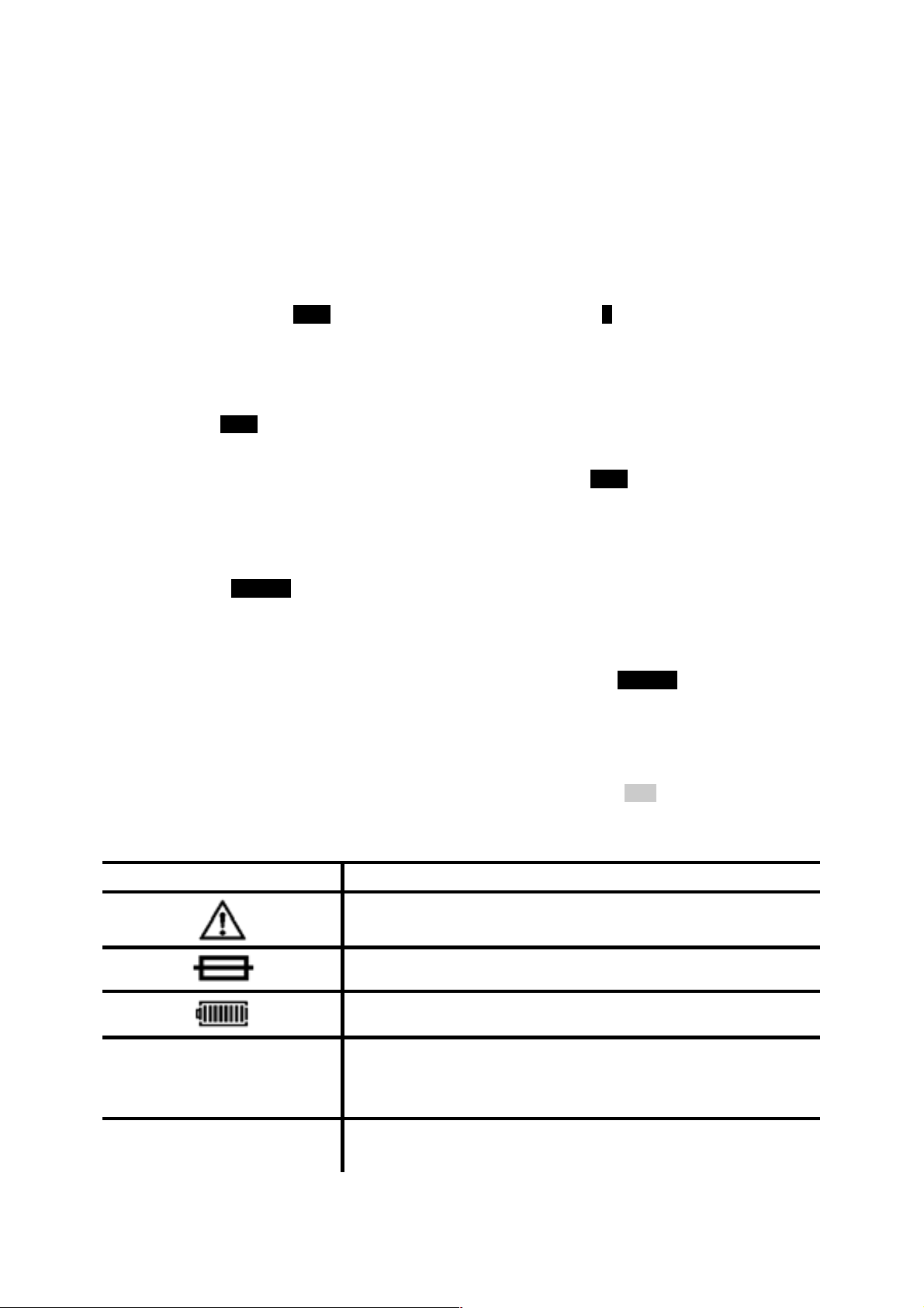
Symbols used on the instrument are:
G Caution: refer to accompanying notes
t Equipment protected throughout by Double Insulation
c Equipment complies with current EU directives
Equipment complies with “C tick” requirements
Do not dispose of in normal waste stream
Note: The safety warnings provided in this document are indicative of safe practice and shall not be
considered exhaustive. Additionally, they are not intended to replace local safety procedures where the
instrument is being used.
Note: This user guide uses the terms ‘earth’ and ‘ground’ interchangeably.
2
Page 3

INTRODUCTION
Thank you for purchasing the Megger Earth Ground Tester.
For your own safety and to get the maximum benefit from your instrument, please ensure that you read
and understand the following safety warnings and instructions before attempting to use the instruments.
This user manual describes the operation and functions of the DET series of Earth Ground Testers:
DET3TA
DET3TC
DET3TD
DET4TD2
DET4TR2
DET4TC2
DET4TCR2
ICLAMP
VCLAMP
CALIBRATION ADAPTOR
TWO-CLAMP CALIBRATION ADAPTOR
These instruments are designed and manufactured by:
Megger Limited
Archcliffe Road
Dover
Kent
CT17 9EN
England
Megger Limited reserves the right to change the specification of these instruments at any time without
prior notice.
3
Page 4

G
Safety Warnings and Precautions must be read and understood before the instrument is used.
Do not leave the instrument connected to the system under test when not in use.
Do not touch circuit connections and exposed metalwork of an installation or equipment under test.
Do not touch the earth stakes, test leads and their terminations (including connections to the
Do not touch the earth stakes, test leads and their terminations (including connections to the
Do not operate the instrument or connect it to any external system if it shows any visible signs of
Do not operate the instrument or connect it to any external system if the battery compartment or
Special precautions are necessary when operating in situations where "live" earths may be
Special precautions are necessary when working near high tension systems (MV and HV): rubber
Special precautions are necessary when working in wet conditions or in agricultural areas: observe
SAFETY WARNINGS
They must be observed during use.
earthing system under test) if an installation earth fault can arise unless adequate precautions are
taken.
earthing system under test) while the instrument is switched on.
damage or if it has been stored for prolonged periods in unfavourable conditions.
casing is open or any parts of the case (including keypad, selector switch, display window, etc.) are
missing.
encountered: isolation switches and fuses (not supplied with this instrument) must be used.
gloves and shoes (not supplied with this instrument) should be worn.
the local safety standards and take all necessary special precautions applicable to the particular
location and do not touch the test leads with bare hands.
Always disconnect the instrument from the earthing system under test while batteries are being
changed or the fuse replaced.
Always replace batteries and fuses with parts of the correct type and rating.
Do not replace the rechargeable cells in the DET4TR2 and DET4TCR2 with non-rechargeable “dry”
cells.
Do not use any other charging equipment other than that supplied by Megger for use with the
DET4TR2 and DET4TCR2.
Do not operate the charging equipment supplied with the DET4TR2 and DET4TCR2 in damp or wet
environments or outside.
NOTE: THE INSTRUMENT MUST ONLY BE USED BY SUITABLY TRAINED
AND COMPETENT PERSONS.
Users of this equipment and/or their employers are reminded that National Health and Safety Legislation
requires them to carry out valid risk assessments of all electrical work so as to identify potential sources of
electrical danger and risk of electrical injury such as inadvertent short circuits. Where the assessments
show that the risk is significant then the use of fused test leads may be appropriate.
4
Page 5

G
LIVE EARTH SAFETY PRECAUTIONS
A 'Live' earth is one that carries current from the mains supply, or could do so under fault conditions. The
following warnings apply in addition to those listed previously.
All persons involved must be trained and competent in isolation and safety procedures for the system
to be worked on. They must be clearly instructed not to touch the earth electrode, test stakes, test
leads, or their terminations if any 'Live' earths may be encountered. It is recommended that they wear
appropriate rubber gloves, rubber soled shoes, and stand on a rubber mat.
The earth electrode under test should be isolated from the circuit it is protecting before testing
commences. If this is not possible, ART may be used to measure electrode resistance.
The instrument terminals should be connected to the system under test through isolation switches
that are rated to handle the likely maximum fault voltages and currents that could be encountered at
the installation. The isolation switch must be open whilst any personal contact is made with the
remote test stakes, or the connecting leads, e.g. when changing their position.
The instrument terminals should be connected to the system under test through fuses that are rated
to handle the likely maximum fault voltages and currents that could be encountered at the
installation.
G
Warning: Whenever battery cells are being fitted or replaced, there should be no connections to the
instrument terminals and the instrument should be switched off.
Warning: To avoid damage by leaking electrolyte or deep discharge, do not leave cells fitted in an
instrument which will remain unused for extended periods of time.
Warning: Incorrect battery cell polarity can cause electrolyte leakage, resulting in damage to the
instrument. If the battery condition indicator does not show a full charge when battery cells are new, a cell
may be reversed.
DET4TR2 and DET4TCR2 ONLY Warning: Only use the cells recommended by Megger, part number
25985-031.
G
BATTERY INSTALLATION
BATTERY CHARGING (DET4TR2 and DET4TCR2 ONLY)
Warning: Whenever battery cells are being recharged, there should be no connections to the instrument
terminals and the instrument should be switched off.
Warning: Do not attempt to recharge non-rechargeable (dry) cells in the DET4TR2 and DET4TCR2.
Doing so will result in instrument damage and may cause personal injury.
Warning: Only use the charging equipment provided by Megger for use with this instrument.
5
Page 6

GENERAL DESCRIPTION
The Megger DET family of test instruments offers a unique solution to the measurement of earth or
ground electrode (rod) resistance and soil resistivity. The family has seven variants supporting 2, 3 and 4wire measurements:
The DET3TA provides 2 and 3-wire measurements and offers an analogue display.
The DET3TC and DET3TD provide 2 and 3-wire measurements and offer a digital display.
The DET4TD2, DET4TR2, DET4TC2 and DET4TCR2 provide 2, 3 and 4-wire measurement and offer a
digital display.
The DET4TR2 and DET4TCR2 provide a rechargeable battery power source.
The DET4TC2 and DET4TCR2 offer variable frequency testing (94 Hz, 105 Hz, 111 Hz and 128 Hz) and
measurement to 200 k).
The DET3TC, DET4TC2 and DET4TCR2 can use an optional current clamp (ICLAMP) to measure
conductor current and electrode (rod) resistance without disconnection, leaving the installation earthing
system intact (Attached Rod Technique, ART).
Additionally, the DET4TC2 and DET4TCR2 can drive an optional voltage-inducing clamp (VCLAMP) which,
in conjunction with the ICLAMP, can be used to make stakeless measurements of the earthing system.
6
Page 7

The DET family have the following features:
Feature DET3TA DET3TD DET3TC DET4TD2 DET4TR2 DET4TC2 DET4TCR2
Automatic C
stake check
Automatic P
stake check
Manual P stake
check
Automatic noise
check
Manual noise
check
Noise rejection
(40 V pk-pk)
Variable
frequency test
2-wire test
3-wire test
4-wire test
2 k range
20 k range
200 k range
No disconnect
testing (ART)
Stakeless
measurement
Voltmeter
(ground noise
voltage
measurement)
Current meter
LCD display
Backlit display
Moving coil
meter
IP54 rated
EN61010-1 100V
CAT IV
Built-in battery
charger
7
Page 8

Each instrument kit comprises the following:
DET instrument
Test leads (for 3-wire instruments, lead lengths are: 3m, 10m and 15m; for 4-wire instruments: 3m,
10m, 10m and 15m)
Test stakes (for 3-wire instruments: 2 stakes are supplied; for 4-wire instruments, 4 stakes are
supplied)
Batteries – 8x AA (LR6) alkaline (except DET4TR2 and DET4TCR2)
Batteries – 8x AA (LR6) 1800 mA hr NiMH (DET4TR2 and DET4TCR2 only)
Warranty card
Calibration certificate (not DET3TA)
Owners CD-ROM manual
Tough polypropylene carrying-case
External AC/DC adaptor (DET4TR2 and DET4TCR2 only)
8
Page 9

PREPARATIONS FOR USE
Batteries
The Megger DET series instruments are supplied with batteries fitted. When batteries become exhausted,
refer to the section on battery replacement or recharging.
Warning: Do not switch the instrument on with the battery cover removed.
Inspection
Before each use of the instrument, visually inspect the instrument case, test leads, stakes and connectors
to confirm that their condition is good, with no damaged or broken insulation.
9
Page 10
GENERAL OPERATING INSTRUCTIONS
OFF
Instrument output voltage selection
The maximum output voltage of the instrument is 50 V. It is possible to reduce this to 25 V for operation
in situations which require it. The most appropriate output voltage should be selected by the operator
based on local safety procedures.
The procedure for changing the output voltage is as follows:
DET3TA:
1. Press and hold the TEST button and switch instrument ON to the V setting using the selector
switch.
2. The needle will sweep across the scaleplate and return to the rest position. [On older DET3TC
and DET3TD instruments, the firmware version will be displayed followed by ‘tst’].
3. Release TEST button. The maximum output test voltage will be displayed, either ‘50 V’ or
‘25 V’.
4. To toggle between the maximum output test voltages, press the TEST button.
5. Switch off instrument when the desired maximum test voltage is displayed.
DET3TC, DET3TD, DET4TD2, DET4TR2, DET4TC2 and DET4TCR2:
1. Press the 25V/50V button after selecting the measurement mode; the display will indicate the
selected output voltage.
Note:
For ART mode, the output voltage is automatically set to 25 V and cannot be changed.
Note: Some older versions of the DET3TC and DET3TD do not have the the 25V/50V button. The
procedure for changing the output voltage is as per the DET3TA.
Auto power down
To extend battery life, the instrument will automatically switch off six minutes after the last operation.
The instrument can be switched back on by turning the selector switch to the O
selecting the desired mode of operation.
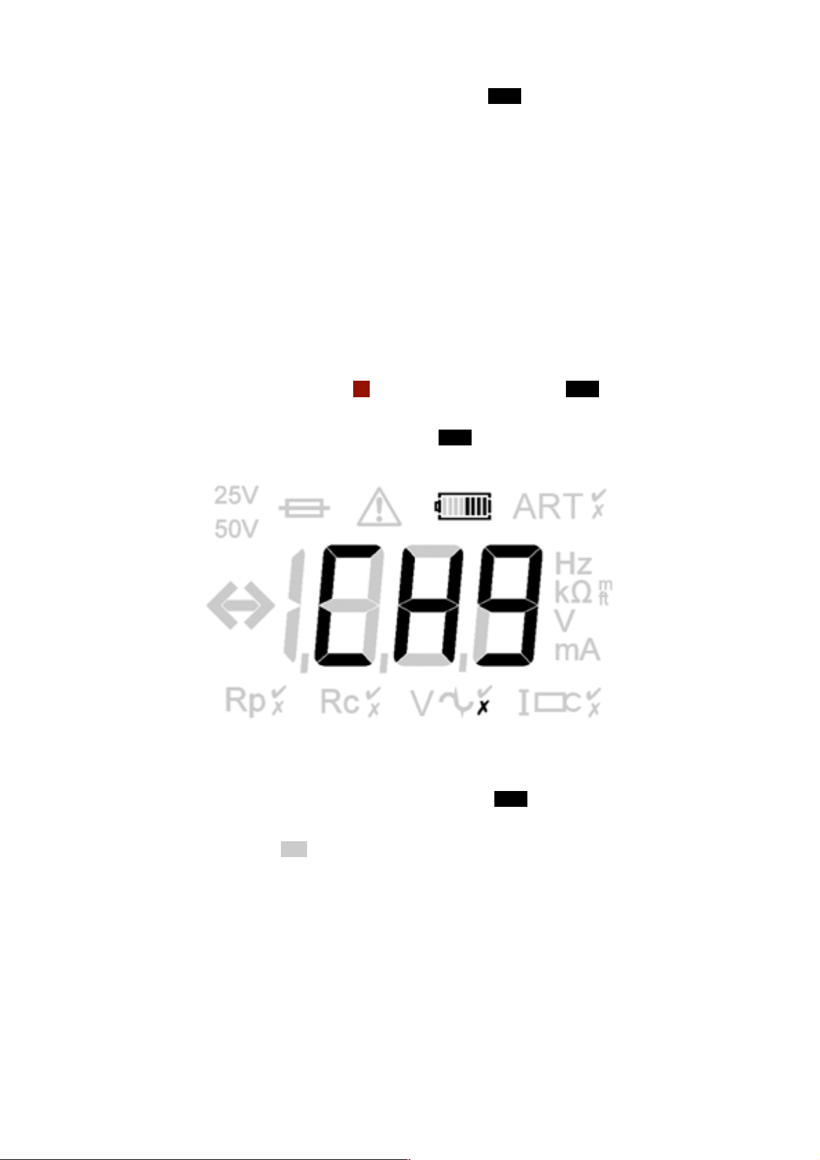
Display symbols (DET3TC, DET3TD, DET4TD2, DET4TR2, DET4TC2 and DET4TCR2)
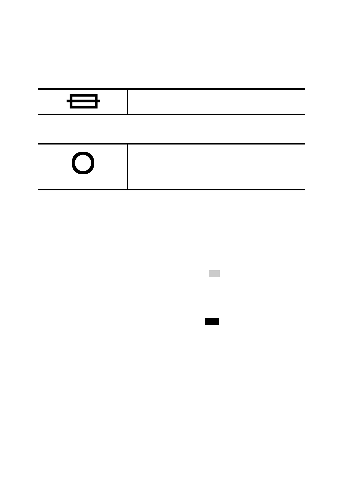
Symbol Meaning
Warning triangle. (Refer to user guide)
Fuse blown.
Battery indicator.
position and then
ART
ART
Situation is suitable for making ART measurements [DET3TC, DET4TC2
and DET4TCR2 only].
Situation is not suitable for making ART measurements [DET3TC,
DET4TC2 and DET4TCR2 only].
10
Page 11
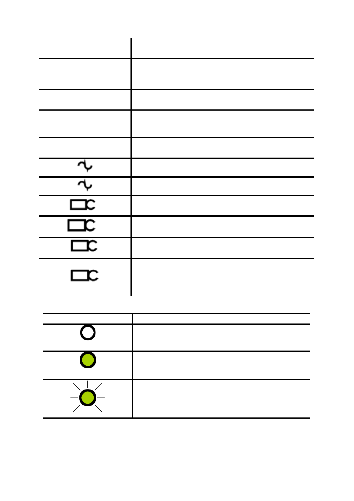
>100V
Rp
Indicates that the ground noise voltage exceeds the instrument
measurement capability (test is inhibited).
Potential stake (P stake) is within range for accurate measurement.
Rp
Rc
Rc
V
V
I
I
Potential stake (P stake) resistance exceeds range for accurate
measurement.
Current stake (C stake) is within range for accurate
Measurement.
Current stake (C Stake) resistance exceeds range for accurate
measurement.
Ground noise voltage is within range for accurate measurement of
resistance.
Ground noise voltage exceeds range for accurate measurement of
resistance.
ICLAMP is connected; VCLAMP is connected [DET3TC, DET4TC2 and
DET4TCR2 only].
ICLAMP is not connected; VCLAMP is not connected [DET3TC, DET4TC2
and DET4TCR2 only].
Sufficient ICLAMP current [DET3TC, DET4TC and DET4TCR only].
I
Insufficient ICLAMP current [DET3TC, DET4TC2 and DET4TCR2 only].
Display symbols (DET3TA)
Symbol Meaning
Rc
Rc
Rc
Current stake (C Stake) resistance exceeds range for accurate
measurement.
OR Fuse blown.
Current stake (C stake) is within range for accurate measurement.
Instrument is performing pre-measurement checks.
11
Page 12
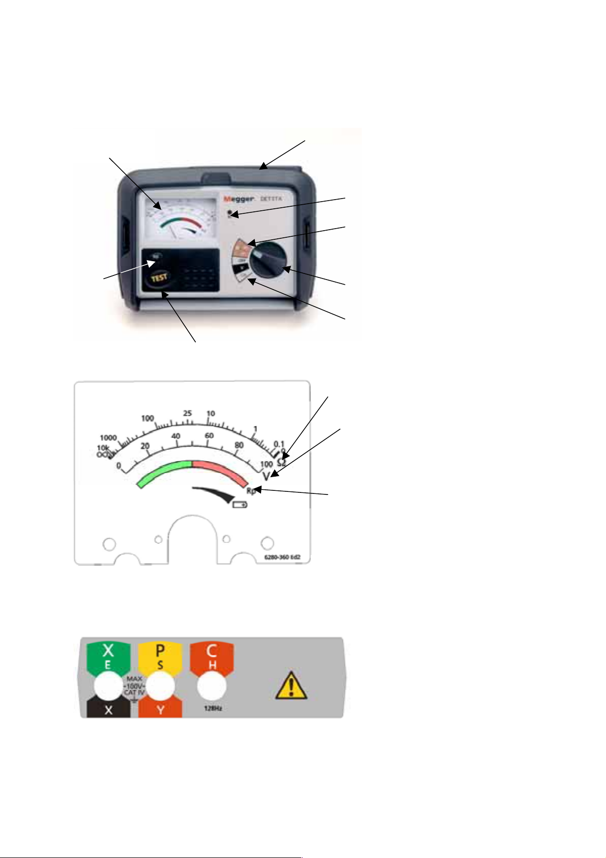
INSTRUMENT ILLUSTRATIONS
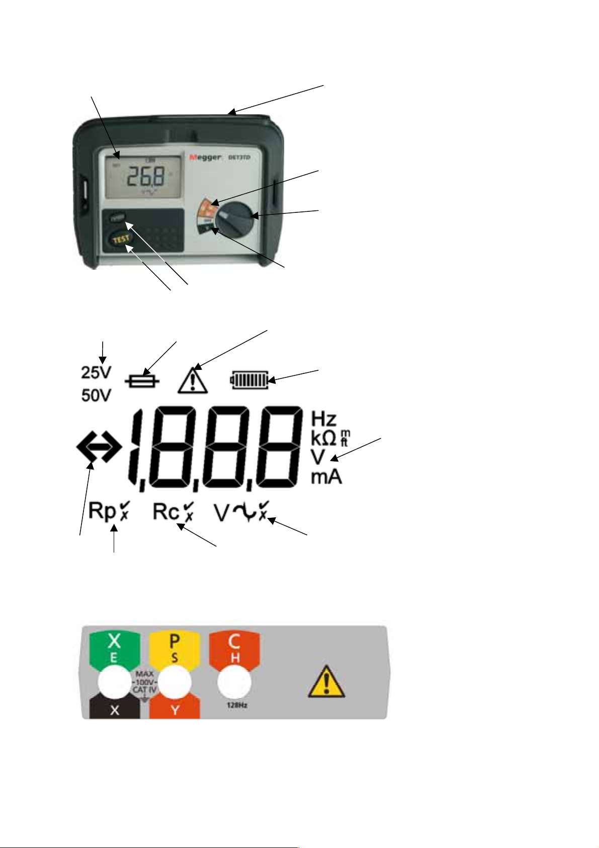
DET3TA
Multi-function
analogue display
Spike
button
Test button
Test lead
connections (at
rear)
Rc OK
Resistance
measurement
settings (2P and
3P)
Selector switch
Battery check setting
voltage setting
Resistance
Voltage scale
scale
Test lead connections (at rear of instrument)
Potential test
spike resistance
indicator
Battery charge
indicator
12
Page 13
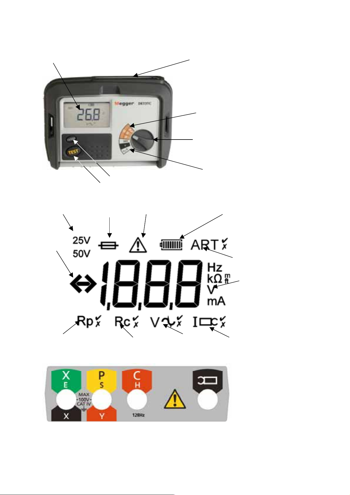
DET3TC
LCD display
Test button
25 V/50 V output
voltage select button
Test lead
connections (at rear)
Resistance
measurement
settings (2P and 3P
and clamp)
Selector switch
Voltage and current
measurement settings
Output voltage
indicator
Over/under
range
indicator
Potential probe
resistance indicator
(OK/Not OK)
Ruptured fuse
indicator
Current probe
resistance (OK/Not
OK)
Warning – refer to
user manual
Ground noise voltage
indicator (OK/Not OK)
Battery charge
indicator
ART measurement
indicator
(Possible/Not
possible
Measuring range
Clamp
current/presence
indicator (OK/Not OK)
Test lead connections (at rear of instrument)
13
Page 14
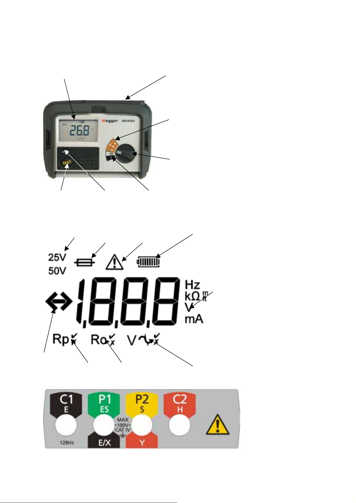
DET3TD
LCD display
25 V/50 V output voltage select button
Test button
Test lead connections (at
rear)
Resistance measurement
settings (2P and 3P)
Selector switch
Voltage measurement settings
Output voltage
indicator
Over/
under
range
indicator
Ruptured fuse
indicator
Potential probe
Resistance indicator
(OK or high)
Warning – refer to
user manual
Current probe resistance
(OK or high)
Battery charge
indicator
Measuring range
Ground noise voltage
indicator (OK high)
Test lead connections (at rear of instrument)
14
Page 15
DET4TD2
LCD display
Test button
Output voltage
indicator
25 V/50 V output
voltage select
button
Ruptured fuse
indicator
Test lead connections
(at rear)
Resistance measurement settings
(2P, 3P and 4P)
Selector switch
Voltage measurement
settings
Warning – refer to
user manual
Battery charge
indicator
Over/under
range
indicator
Potential probe
resistance indicator
(OK or high)
Current probe
resistance (OK or
high)
Measuring range
Ground noise voltage
indicator (OK high)
Test lead connections (at rear of instrument)
15
Page 16

DET4TR2
LCD display
Test button
Output voltage
indicator
Test lead connection
(at rear)
25 V/50 V output
voltage select button
Ruptured fuse
indicator
Resistance measurement settings
(2P, 3P and 4P)
Selector switch
Voltage measurement
settings
Warning – refer to
user manual
Over/
under
range
indicator
Potential probe
Resistance indicator
(OK or high)
Current probe resistance
(OK or high)
Battery charge
indicator
Measuring range
Ground noise voltage
indicator (OK high)
Test lead connections (at rear of instrument)
16
Page 17

DET4 TC2
LCD display
Test lead connections
(at rear)
Resistance measurement settings
Selector switch
Voltage and current
measurement settings
Test button
Output voltage
indicator
Over/under
range
indicator
Frequency select button
25 V/ 50 V output
voltage select button
Ruptured fuse
indicator
Backlight control button
Warning – refer to
user manual
Battery charge
indicator
ART measurement
indicator
(Possible/Not
possible
Measuring range
Potential probe
resistance indicator
(OK/Not OK)
Test lead connections (at rear of instrument)
Current probe
resistance (OK/Not
OK)
Ground noise voltage
indicator (OK/Not OK)
Clamp
current/presence
indicator (OK/Not OK)
17
Page 18
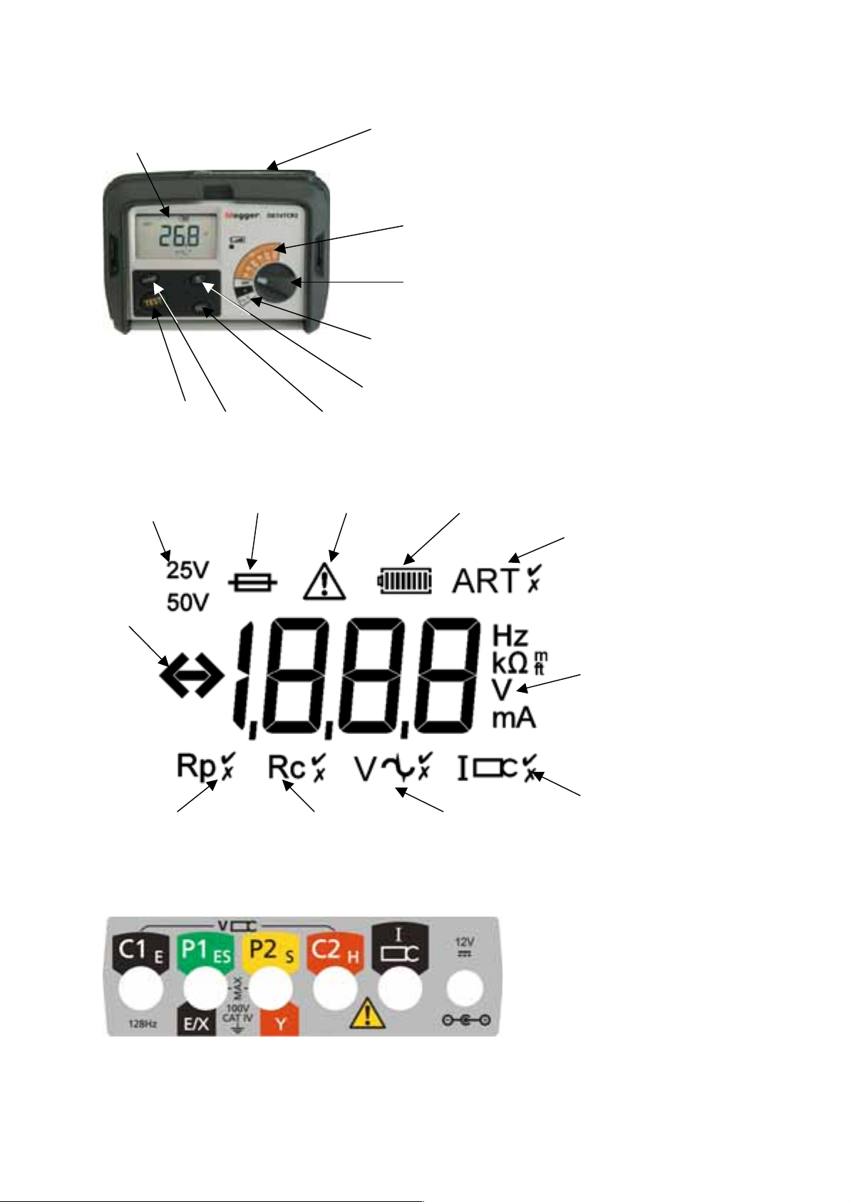
DET4TCR2
LCD display
Test button
Output voltage
indicator
Over/under
range
indicator
25 V/ 50 V output
voltage select button
Ruptured fuse
indicator
Test lead
connections
(at rear)
Resistance measurement settings
Selector switch
Frequency select button
Warning – refer to
user manual
Voltage and current
measurement settings
Backlight control button
Battery charge
indicator
ART measurement
indicator
(Possible/Not
possible
Potential probe
resistance indicator
(OK/Not OK)
Current probe
resistance (OK/Not
OK)
Test lead connections (at rear of instrument)
Ground noise voltage
indicator (OK/Not OK)
Measuring range
Clamp
current/presence
indicator (OK/Not OK)
18
Page 19
BATTERY
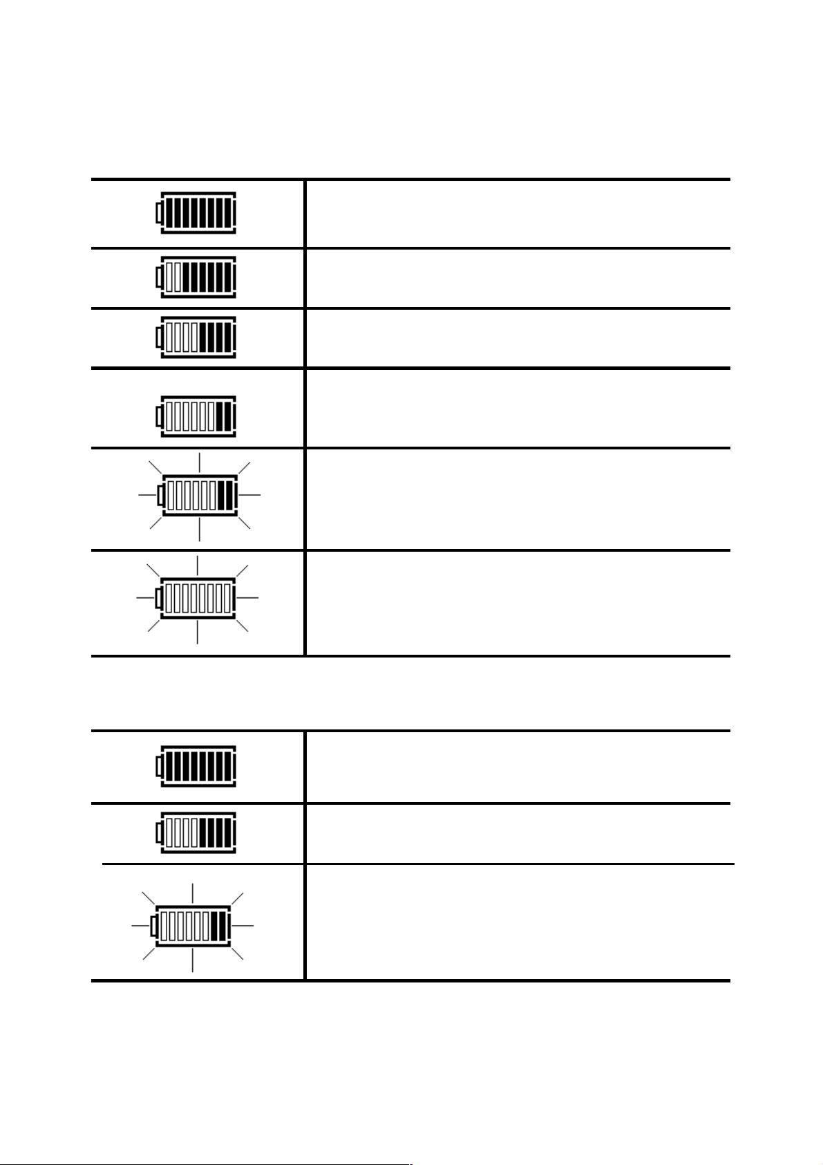
Battery status indication (DET3TC, DET3TD, DET4TD2 and DET4TC2)
The battery condition indicator is displayed whilst the instrument is switched on as shown:
100% battery charge remaining.
75% battery charge remaining.
50% battery charge remaining.
25% battery charge remaining.
Some charge remaining, but instrument may auto power
down at any time.
0% battery charge remaining – instrument will auto power
down.
Battery status indication (DET4TR2 and DET4TCR2)
The battery condition indicator is displayed whilst the instrument is switched on as shown:
Full battery charge – shown immediately after charging.
Nearly fully battery charge.
Some change remaining, but instrument may auto power
down at any time.
19
Page 20

0% battery charge remaining – instrument will auto power
down.
Note: If the DET4TR2 and DET4TCR2’s rechargeable batteries are replaced with alkaline batteries the
instrument may automatically disable its charging circuit to prevent inadvertent charging of nonrechargeable cells. Follow the instructions ‘Re-enabling the DET4TR2 and DET4TCR2 charger circuit’ to
switch the charger back on when the NiMH cells are re-inserted.
Battery status indication (DET3TA)
1. Set the rotary selector switch to the position.
2. Press and hold the TEST button.
3. The battery charge level will be indicated on the scaleplate as shown in Figure 1.
Figure 1: battery charge level indicator
4. Release the TEST button.
Battery charging (DET4TR2 and DET4TCR2)
When the battery status indicator shows a nearly empty or exhausted battery, the instrument may be
recharged using the following procedure.
Warning: Do not attempt to operate the instrument whilst the external AC/DC adaptor is connected.
Warning: Do not attempt to recharge non-rechargeable (dry) cells in the DET4TR2 and DET4TCR2.
Doing so will result in instrument damage and may cause personal injury. Only use the cells
recommended by Megger.
Warning: Only use the external charging equipment provided by Megger.
1. To avoid the possibility of electric shock, switch instrument OFF and disconnect the instrument
from any electrical circuits.
2. Move the slide on the terminal panel until the external AC/DC adaptor socket is exposed.
20
Page 21

3. Remove the bung from the AC/DC adaptor socket.
4. Connect the AC/DC adaptor and switch on.
5. The charging cycle will commence and last approximately 17 hours. Follow the progress using the
charge status LED as shown in Figure 2.
NOTE: The instrument ambient temperature should be between +10ºC (50ºF) and +40ºC (105ºF)
during the charging cycle.
Figure 2: charge status LED progression
Battery charging complete.
Battery charging in progress.
Defective/non-rechargeable cells detected or no batteries
present.
Defective/non-rechargeable cells detected or no batteries
present. Charging terminated.
Battery type
DET3TA, DET3TC, DET3TD, DET4TD2 , DET4TC2: 8 x AA (LR6) 1.5V Alkaline.
Megger part number: 25511-841.
DET4TR2, DET4TCR2: 8 x AA (LR6) 1.2V NiMH 1800mAhr.
Megger part number: 25985-031.
Battery replacement
Battery replacement
Warning: Do not operate instrument with the battery cover removed.
Warning: Incorrect battery cell polarity can cause electrolyte leakage, resulting in damage to the
instrument. If the battery condition indicator does not show a full charge when battery cells are new, a cell
may be reversed.
Warning: To avoid damage by leaking electrolyte or deep discharge, do not leave cells fitted in an
instrument, which will remain unused for extended periods of time.
1. To avoid the possibility of electric shock, switch instrument OFF and disconnect the instrument
from any electrical circuits.
2. The rear cover must not be opened if the test leads are connected.
21
Page 22
3. To avoid the possibility of electric shock, do not press the TEST button or touch the fuse when
changing batteries.
4. To remove the rear cover, release the screw at the bottom of the cover and lift the cover upwards.
5. Remove the exhausted cells and dispose of in an appropriate manner.
6. Refit new batteries of the correct type observing the correct polarity as marked on the battery
compartment.
7. Replace the instrument back cover and secure by tightening the retaining screw.
Re-enabling the battery charging circuit on the DET4TR2 and DET4TCR2
If the DET4TR2 and DET4TCR2’s rechargeable batteries are replaced with alkaline batteries the instrument
may automatically disable its charging circuit to prevent inadvertent charging of non-rechargeable cells.
Follow the instructions below to switch the charger back on when the NiMH cells are re-inserted.
1. Switch the instrument on in to the 4P position while holding down the TEST button. The display
will carry out a self test then briefly display the software version number.
2. The screen will show the letters ‘tst’ – release the TEST button.
3. The Charger Enable Screen will be shown (see below)
4. The state of the charger circuit is shown by either a cross or a tick being shown below the letters
‘CHg’. A cross indicates that the charger circuit is disabled.
5. If the cross is shown, re-enable the charger by pressing the TEST button once (the cross should
change to a tick).
6. Switch the instrument OFF to save the new setting.
22
Page 23
FUSE
Fuse status indication (DET3TC, DET3TD, DET4TD2, DET4TR2, DET4TC2
and DET4TCR2)
The fuse blown status indicator is displayed whilst the instrument is switched on and performing a test as
shown:
Fuse blown.
Fuse status indication (DET3TA)
The fuse blown indication is given by the Rc LED when performing a test as shown:
Fuse blown.
Rc
Fuse type
All instruments: 500 mA (F), HBC (50 kA, 600 V), 32mm x 6mm.
Megger part number: 25950-056.
Fuse replacement
Warning: Do not operate instrument with the battery cover removed.
Warning: Fitting an incorrect fuse type will reduce operator safety.
1. To avoid the possibility of electric shock, switch instrument OFF and disconnect the instrument
from any electrical circuits.
2. The rear cover must not be opened if the test leads are connected.
3. To remove the rear cover, release the screw at the bottom of the cover and lift the cover upwards.
4. To avoid the possibility of electric shock, do not press the TEST button when changing the fuse.
5. Remove the ruptured fuse.
6. Refit new fuse of the correct type.
7. Replace the instrument back cover and secure by tightening the retaining screw.
23
Page 24
DESCRIPTION OF TESTS
The description of tests contained within this user guide are instructions for the use of the DET family of
instruments by competent persons.
Suitable applications
Where there is doubt about a particular application, reference should be made to the advice and guidance
contained in the publication, “Getting Down to Earth” which is available from Megger, part number 21500-
072.
The DET range of instruments can be used in agricultural locations (as per IEC 61557-5). In these
circumstances, the output voltage should be switched to 25 V in order to comply with the standard.
The DET range of instruments makes resistance measurements using a switched DC signal at a frequency
of 128 Hz. The DET4TC2 and DET4TCR2 provide the user with the option to select 94 Hz,
105 Hz, 111 Hz or 128 Hz as the test frequency.
Note about measurements: when connecting the instrument to electrodes, ensure that any leads and
cables are fully unwound and laid out without loops.
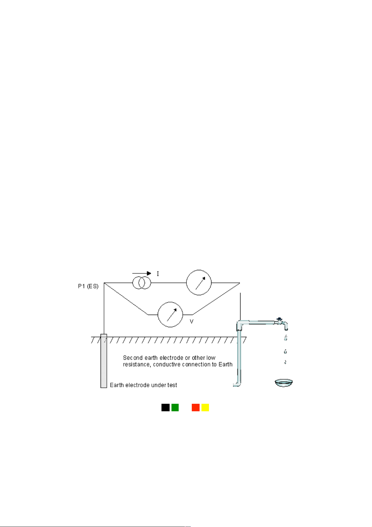
Principle of operation (two-terminal resistance measurement)
This technique is used to measure the resistance between two earth points, e.g. between an earth
electrode of unknown resistance and a known “good” ground connection such as metallic underground
pipework or building steelwork.
The DET injects an a.c. current of known magnitude into the system under test and measures the voltage
developed across it as shown in Figure 3. The system resistance is a simple ratio as per Ohm’s Law, i.e.
R=V/I.
Figure 3: schematic for two-terminal resistance measurement
C1 (E/X)
P2 (P/S)
C2 (C/H)
The DET instruments automatically link the C1-P1 and C2-P2 terminals when a two-terminal test is
selected.
24
Page 25
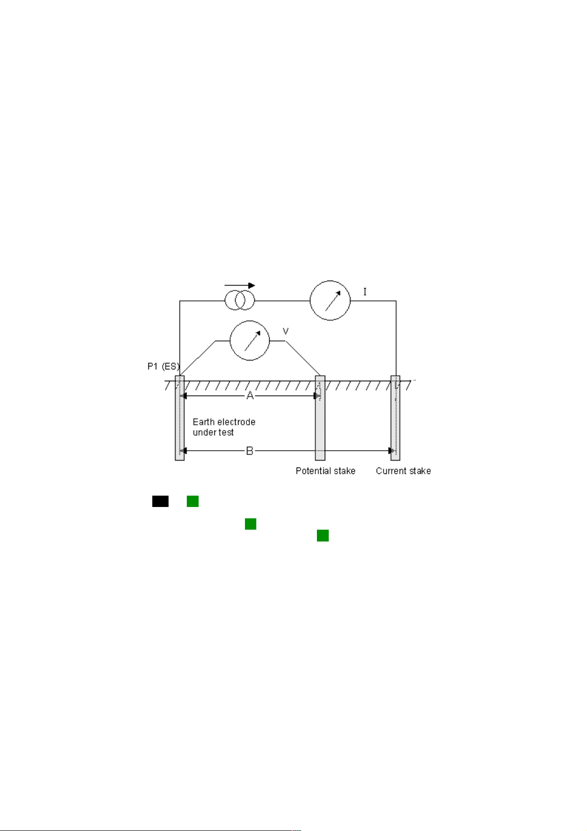
Principle of operation (three-terminal resistance measurement)
The classic “fall of potential” test is used to accurately measure the resistance of an earth electrode using
auxiliary stakes driven into the soil, which form a circuit for the test current injection and voltage
measurement as used for the two-terminal method.
The DET injects an a.c. current of known magnitude into the system under test and measures the voltage
developed across it as shown in Figure 4. The system resistance is a simple ratio as per Ohm’s Law. In this
case, the potential stake is moved by fixed increments in a straight line between the electrode under test
and the current stake. At each location, the resistance is calculated as R=V/I. A graph of resistance versus
potential stake position is plotted and the resistance of the electrode under test is taken to be the point at
which the curve is flattest.
Empirical testing has shown that with suitably positioned stakes, this method can be shortened by placing
the potential stake at a distance of approximately 62% between the electrode under test and the current
stake, i.e. at A = 0.62 x B.
Figure 4: schematic for three-terminal resistance measurement with lead null
C1 (E/X)
C2 (C/H) P2 (P/S)
In this diagram, the C11and P1 terminals are connected together at the electrode under test. This is the
“three-terminal with lead null” configuration which is only applicable in four-terminal testers. This
configuration allows the resistance of the P1 lead to the electrode under test to be “nulled” out. For threeterminal testers or when lead null is not required, only the P1 terminal (or X terminal on a three-terminal
instrument) connects to the electrode under test. This is shown in Figure 5.
25
Page 26

Figure 5: schematic for three-terminal resistance measurement without lead null
Principle of operation (three-terminal resistance measurement using
ART)
The classic three-terminal test method has a disadvantage, namely that the electrode under test must be
disconnected from the system it is supposed to protect in the event of a power system fault. The reason
for this is that the injected test current will take all possible routes to ground and not all of it will
necessarily flow through the electrode under test. In this case, the instrument will make a reading of the
entire earthing network, not just the individual electrode.
By using a current transducer (the Megger ICLAMP) to measure the current flowing through the electrode
under test as a fraction of the total test current injected, the instrument can determine the individual
resistance. This arrangement is shown in Figure 6.
Figure 6: schematic for three-terminal resistance measurement using
ART without lead null
In this configuration, the injected test current I splits along two paths into I1 (flowing into the connected
earthing system) and I2 (flowing into the electrode under test, i.e. I=I1+I2. The resistance of the
26
Page 27

electrode under test is calculated as R=V/I2 or R=V/(I-I1). The current transducer (ICLAMP) measures I2
and feeds this value back to the instrument.
Principle of operation (two-clamp stakeless resistance measurement)
In this example, the electrode under test is connected to a network of other electrodes. It is either
impractical or unsafe to disconnect an individual electrode for testing. Also, there might be insufficient
space to perform a classic three-terminal resistance measurement. The stakeless test method using both
VCLAMP and ICLAMP can be used to obtain a measurement for the electrode under test.
A defined test voltage is injected into the system using the VCLAMP, inducing a current, I, to flow and be
measured by the ICLAMP. The model shown in Figure 7 can be simplified to the resistance of the
electrode under test, Rx and the resistance of the other electrodes in parallel, i.e. R1 || R2 || … || Rn.
Therefore, the current induced by the test voltage is I=V/[R
resistance of the other electrodes in parallel approaches zero, then the resistance measured, approaches
the value of the electrode under test.
Figure 7: schematic for two-clamp stakeless resistance measurement
+(R1 || R2 || … || Rn)]. It follows that as the
x
27
Page 28

Principle of operation (four-terminal resistivity measurement)
The soil resitivity measurement works on a similar principle to the other measurements which use stakes:
a current is injected around an outer loop and a voltage measured, shown in Figure 8. In this case,
however, the measurement made by the instrument requires further conversion using a formula to derive
the volumetric soil resistivity from the resistance value display.
Figure 8: schematic for 4-terminal resistivity measurement
For this test, the relative spacing and depth of the stakes is important. When configured as shown in
Figure 8, the soil resistivity can be calculated from the resistance value, R, displayed on the instrument as
RA2 =
.
28
Page 29

Measurement of ground noise voltage (DET3TC, DET3TD, DET4TD2,
DET4TR2, DET4TC2 and DET4TCR2)
1. Ensure the rotary selector switch is in the OFF position.
2. Connect the instrument as shown in Figure 9.
Figure 9: instrument connection for measuring ground noise voltage
Potential stake
Electrode
under test
Electrode
under test
Potential stake
DET3TD
DET4TD2
DET4TR2
DET4TD
29
Page 30

Electrode
under test
Potential stake
DET3TC
3. Set the rotary selector switch to the V position.
4. The ground noise voltage reading will be displayed as shown in Figure 10.
Figure 10: example ground noise voltage reading (DET4 display shown)
30
Page 31

Note:
The instrument will display the warning triangle and an excessive noise voltage indicator above
40 V pk-pk (14 Vrms).
The instrument will display the warning triangle and an over-range condition above 100 V.
Measurement of ground noise voltage (DET3TA)
1. Ensure the rotary selector switch is in the OFF position.
2. Connect the instrument as shown in Figure 11.
Figure 11: instrument connection for measuring ground noise voltage
Potential stake
Electrode
under test
3. Set the rotary selector switch to the V position.
4. The ground noise voltage reading will be indicated on the scaleplate as shown in Figure 12.
Figure 12: example ground noise voltage reading
31
Page 32

Two-terminal resistance measurement (DET3TC, DET3TD, DET4TD2,
DET4TR2, DET4TC2 and DET4TCR2)
1. Ensure the rotary selector switch is in the OFF position.
2. Connect the instrument as shown in Figure 13.
Figure 13: instrument connection for measuring two-terminal resistance
Metallic interconect
Electrode
under test
Electrode
under test
Metallic interconnect
DET4TD2
DET4TR2
DET3TD
DET4TD
32
Page 33
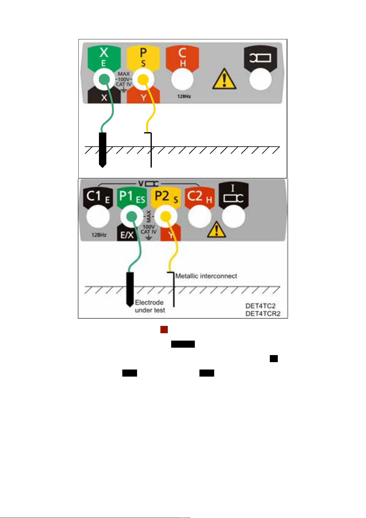
Electrode
under test
Metallic interconnect
DET3TC
3. Set the rotary selector switch to the 2P position.
4. Select the desired test voltage using the 25V/50V button.
5. DET4TC2 and DET4TCR2 only: Select the desired test frequency using the Hz button.
6. Press and release the TEST button (by holding the TEST button, the resistance measurement will
be continually updated).
7. The instrument will perform pre-measurement check, the status of which will be indicated on the
display.
8. The two-terminal resistance reading will be displayed as shown in Figure 14.
33
Page 34

Figure 14: example two-terminal resistance reading (DET4 display shown)
Note:
The test voltage used to make the two-terminal resistance reading is a.c. and may not be suitable for
continuity testing according to some local regulations.
The instrument will display the warning triangle and an excessive noise voltage indicator if the ground
noise voltage is above 40 V pk-pk (14 Vrms).
The instrument will display the warning triangle and a voltage over-range condition if the ground
noise voltage is above 100 V – no resistance reading is possible under these conditions.
34
Page 35
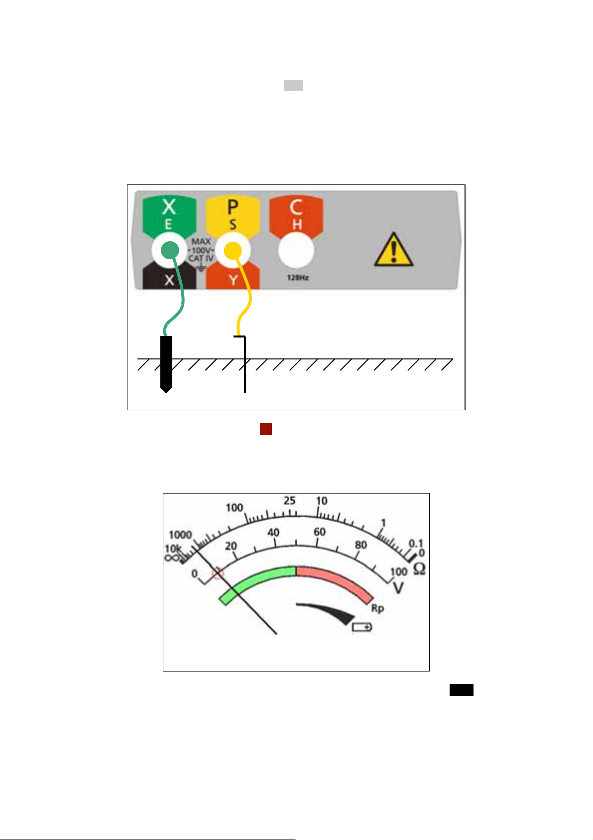
Two-terminal resistance measurement (DET3TA)
1. Ensure the rotary selector switch is in the OFF position.
2. Select the desired test voltage using the procedure in the section on General Operating
Instructions.
3. Connect the instrument as shown in Figure 15.
Figure 15: instrument connection for measuring two-terminal resistance
Metallic interconnect
Electrode
under test
4. Set the rotary selector switch to the 2P position.
5. The ground noise voltage will be indicated on the scale plate as shown in Figure 16.
Figure 16: ground noise voltage indication
6. If the ground noise voltage is less than 40 V pk-pk (14 V rms), press and hold the TEST button.
[Testing will be inhibited if the ground noise voltage exceeds 40 V pk-pk.]
7. The Rc LED will flash to indicate that the instrument is carrying out pre-measurement checks.
35
Page 36
8. If the Rc LED does not illuminate following the pre-measurement checks, this indicates that the
instrument fuse has ruptured.
9. If the Rc LED illuminates solidly following the pre-measurement checks, this indicates that a twoterminal measurement can be made.
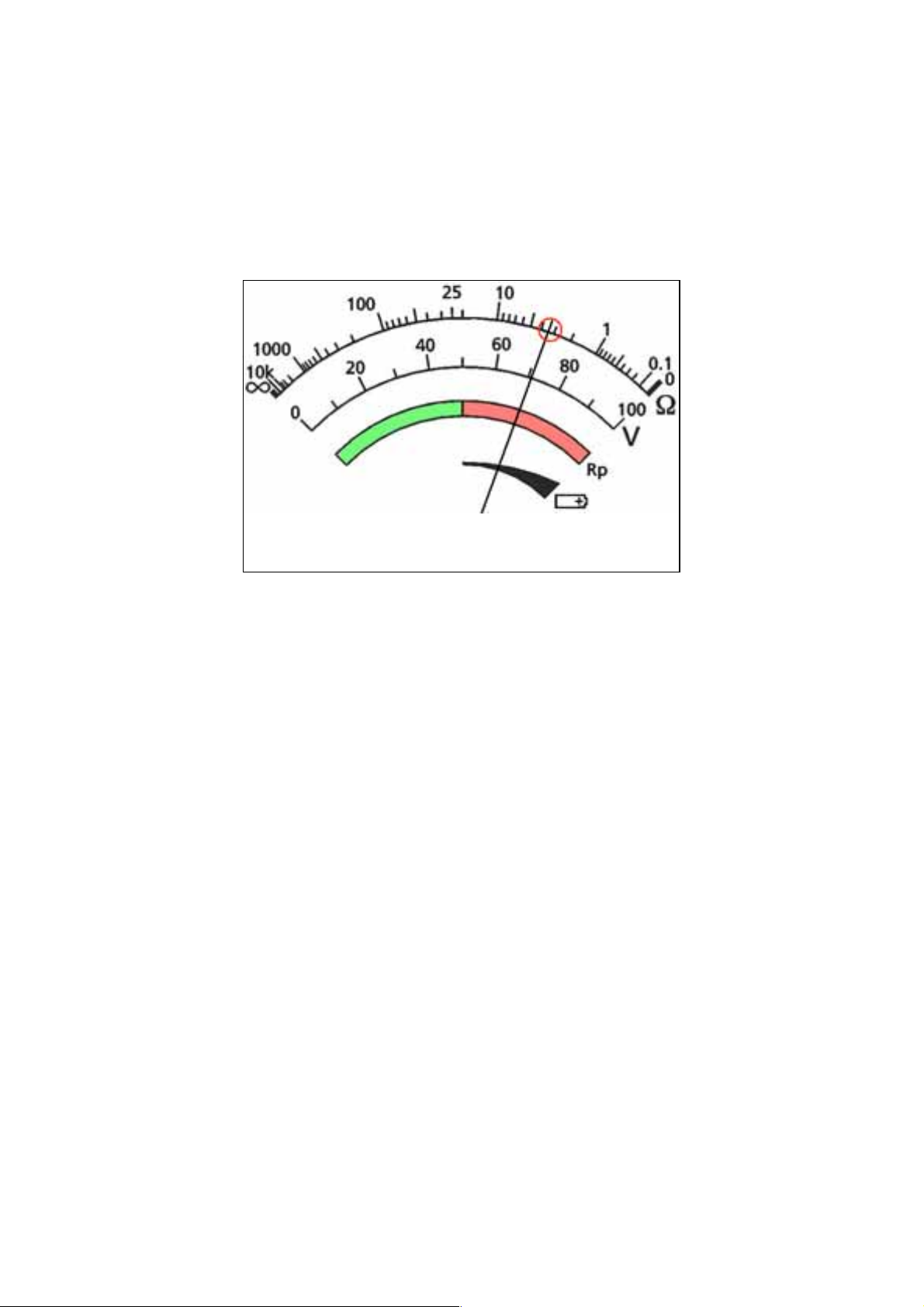
10. The two-terminal resistance reading will be indicated on the scaleplate as shown in Figure 17.
Figure 17: example two-terminal resistance reading
Note:
The test voltage used to make the two-terminal resistance reading is a.c. and may not be suitable for
continuity testing according to some local regulations.
No resistance reading is possible if the ground noise voltage exceeds 100 V.
36
Page 37
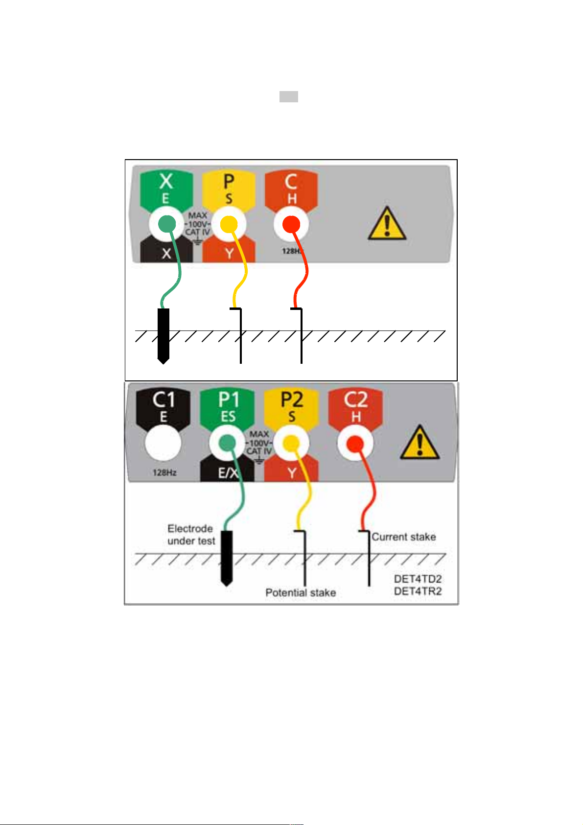
Three-terminal resistance measurement (DET3TC, DET3TD, DET4TD2,
DET4TR2, DET4TC2 and DET4TCR2)
1. Ensure the rotary selector switch is in the OFF position.
2. Connect the instrument as shown in Figure 18.
Figure 18: instrument connection for measuring three-terminal resistance
Electrode
under test
Potential stake
Current stake
DET3TD
37
Page 38
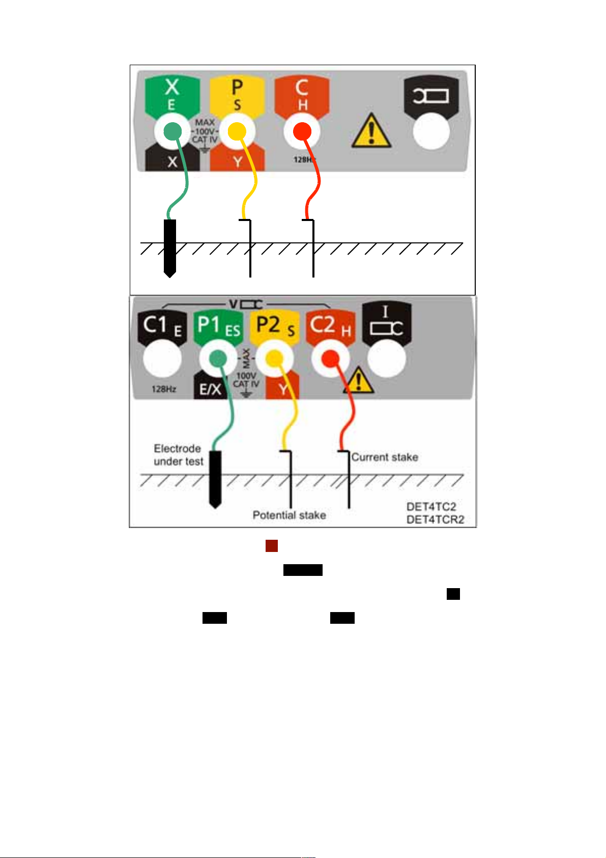
Electrode
under test
Current stake
Potential stake
3. Set the rotary selector switch to the 3P position.
4. Select the desired test voltage using the 25V/50V button.
DET3TC
5. DET4TC2 and DET4TCR2 only: Select the desired test frequency using the Hz button.
6. Press and release the TEST button [by holding the TEST button, the resistance measurement will
be continually updated].
7. The instrument will perform pre-measurement check, the status of which will be indicated on the
display.
8. The three-terminal resistance reading will be displayed as shown in Figure 19.
38
Page 39

Figure 19: example three-terminal resistance reading
(DET4 display shown)
Note:
The instrument will display the warning triangle and an excessive noise voltage indicator if the ground
noise voltage is above 40 V pk-pk (14 Vrms).
The instrument will display the warning triangle and a voltage over-range condition if the ground
noise voltage is above 100 V – no resistance reading is possible under this condition.
39
Page 40
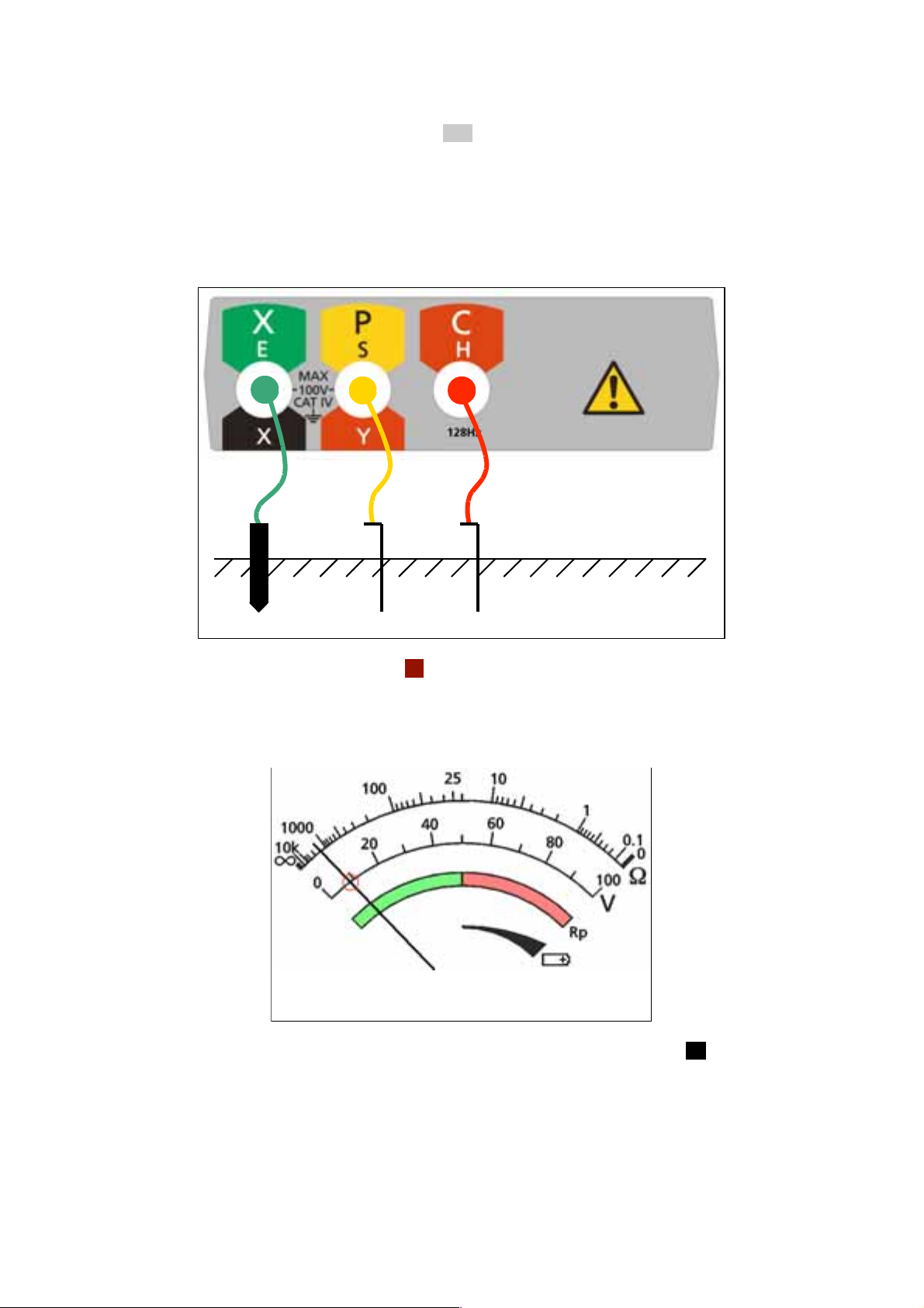
Three-terminal resistance measurement (DET3TA)
1. Ensure the rotary selector switch is in the OFF position.
2. Select the desired test voltage using the procedure in the section on General Operating
Instructions.
3. Connect the instrument as shown in Figure 20.
Figure 20: instrument connection for measuring three-terminal resistance
Electrode
under test
Current stake
Potential stake
4. Set the rotary selector switch to the 3P position.
5. The ground noise voltage will be indicated on the scaleplate as shown in Figure 21.
Figure 21: ground noise voltage indication
6. If the ground noise voltage is less than 40Vpk-pk (14Vrms), press and hold the Rp button.
[Testing will be inhibited if the ground noise voltage exceeds 40Vpk-pk.]
7. The P stake resistance will be indicated on the scaleplate: the needle will move into the green
region (Figure 22) if the P stake resistance is within limits for an accurate measurement and into
the red region (Figure 23) if the P stake resistance exceeds the limits for an accurate
measurement.
40
Page 41

Figure 22: P stake resistance OK (green region)
Figure 23: P stake resistance not OK (red region)
8. If the P stake resistance is acceptable (needle in the green region of the scaleplate), release the
Rp button.
9. Press and hold the TEST button.
10. The Rc LED will flash to indicate that the instrument is carrying out pre-measurement checks.
11. If the Rc LED does not illuminate following the pre-measurement checks, this indicates that the C
stake resistance exceeds the limits for an accurate measurement or that the instrument fuse has
ruptured.
12. If the Rc LED illuminates solidly following the pre-measurement checks, this indicates that a
three-terminal measurement can be made.
13. The three-terminal resistance reading will be indicated on the scaleplate as shown in Figure 24.
41
Page 42

Figure 24: example three-terminal resistance reading
Note:
No resistance reading is possible if the ground noise voltage exceeds 100 V.
42
Page 43

Three-terminal resistance measurement with lead null (DET4TD2,
DET4TR2, DET4TC2 and DET4TCR2)
In certain circumstances, the resistance of the test lead connecting to the electrode under test may itself
form a significant part of the measurement electrode resistance. This effect can be eliminated using the
lead-null technique described in this section.
1. Ensure the rotary selector switch is in the OFF position.
2. Connect the instrument as shown in Figure 25.
Figure 25: instrument connection for measuring three-terminal resistance
with lead-null
3. Set the rotary selector switch to the 4P position.
4. Select the desired test voltage using the 25 V/50 V button.
5. DET4TC2 and DET4TCR2 only: Select the desired test frequency using the Hz button.
43
Page 44

6. Press and release the TEST button [by holding the TEST button, the resistance measurement will
be continually updated].
7. The instrument will perform pre-measurement check, the status of which will be indicated on the
display.
8. The three-terminal resistance with lead-null reading will be displayed as shown in Figure 26.
Figure 26: example three-terminal resistance with lead-null reading
(DET4 display shown)
Note:
The instrument will display the warning triangle and an excessive noise voltage indicator if the ground
noise voltage is above 40 V pk-pk (14 Vrms).
The instrument will display the warning triangle and a voltage over-range condition if the ground
noise voltage is above 100 V – no resistance reading is possible under this condition.
44
Page 45

Four-terminal resistivity measurement (DET4TD, DET4TR2, DET4TC2 and
DET4TCR2)
The DET4TD2, DET4TR2, DET4TC2 and DET4TCR2 can be used to make soil resistivity measurements.
The resistivity value can be derived from the four-terminal resistance reading made by the instrument and
the particular separation and depth of the stakes.
1. Ensure the rotary selector switch is in the OFF position.
2. Connect the instrument as shown in Figure 27.
Figure 27: instrument connection for measuring four-terminal resistance
3. Set the rotary selector switch to the 4P position.
4. Select the desired test voltage using the 25 V/50 V button.
5. DET4TC2 and DET4TCR2 only: Select the desired test frequency using the Hz button.
6. Press and release the TEST button [by holding the TEST button, the resistance measurement will
be continually updated].
7. The instrument will perform pre-measurement check, the status of which will be indicated on the
display.
8. The four-terminal resistance reading will be displayed as shown in Figure 28.
45
Page 46

Figure 28: example four-terminal resistance reading (DET4 display shown)
9. A soil resistivity value can be derived from the resistance reading and the stake geometry.
Note:
The instrument will display the warning triangle and an excessive noise voltage indicator if the ground
noise voltage is above 40 V pk-pk (14 Vrms).
The instrument will display the warning triangle and a voltage over-range condition if the ground
noise voltage is above 100 V – no resistance reading is possible under this condition.
46
Page 47

Measurement of ground current (DET3TC, DET4TC2 and DET4TCR2)
Before measuring ground current, please follow the procedure contained in the section on ICLAMP
calibration.
1. Ensure the rotary selector switch is in the OFF position.
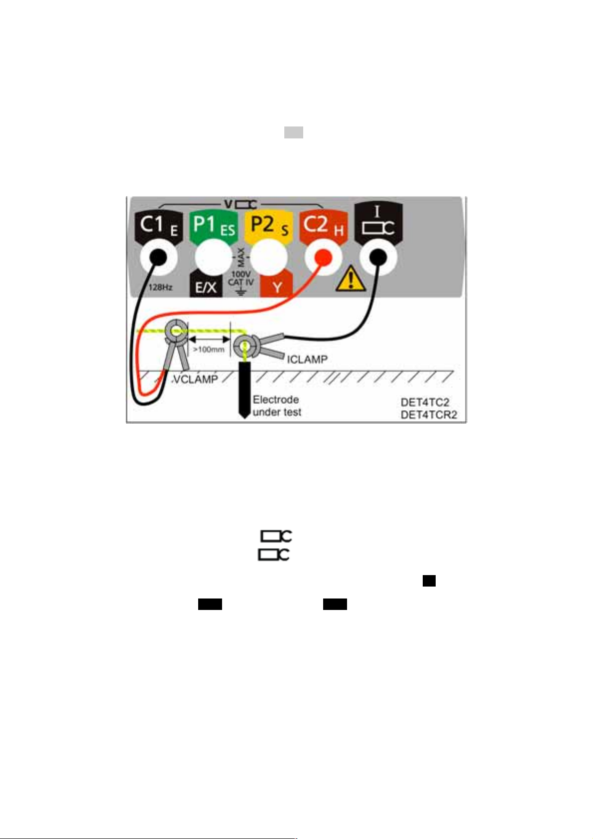
2. Connect the instrument as shown in Figure 29.
Figure 29: instrument connection for measuring ground current
Installation
earthing
conductor
ICLAMP
Electrode
under test
Installation
earthing
ICLAMP
conductor
Electrode
under test
3. Close the ICLAMP around the conductor under test.
DET3TC
DET4TCR2
DET4TC2
4. Set the rotary selector switch to the A position.
5. The ground current flowing in the conductor will be displayed as shown in Figure 30.
47
Page 48

Figure 30: example ground current reading (DET4 display shown)
Note:
The instrument will display the warning triangle above 2 A – no ART testing is possible under this
condition.
The instrument will display the warning triangle and an over-range condition above 20 A – no ART
testing is possible under this condition.
48
Page 49
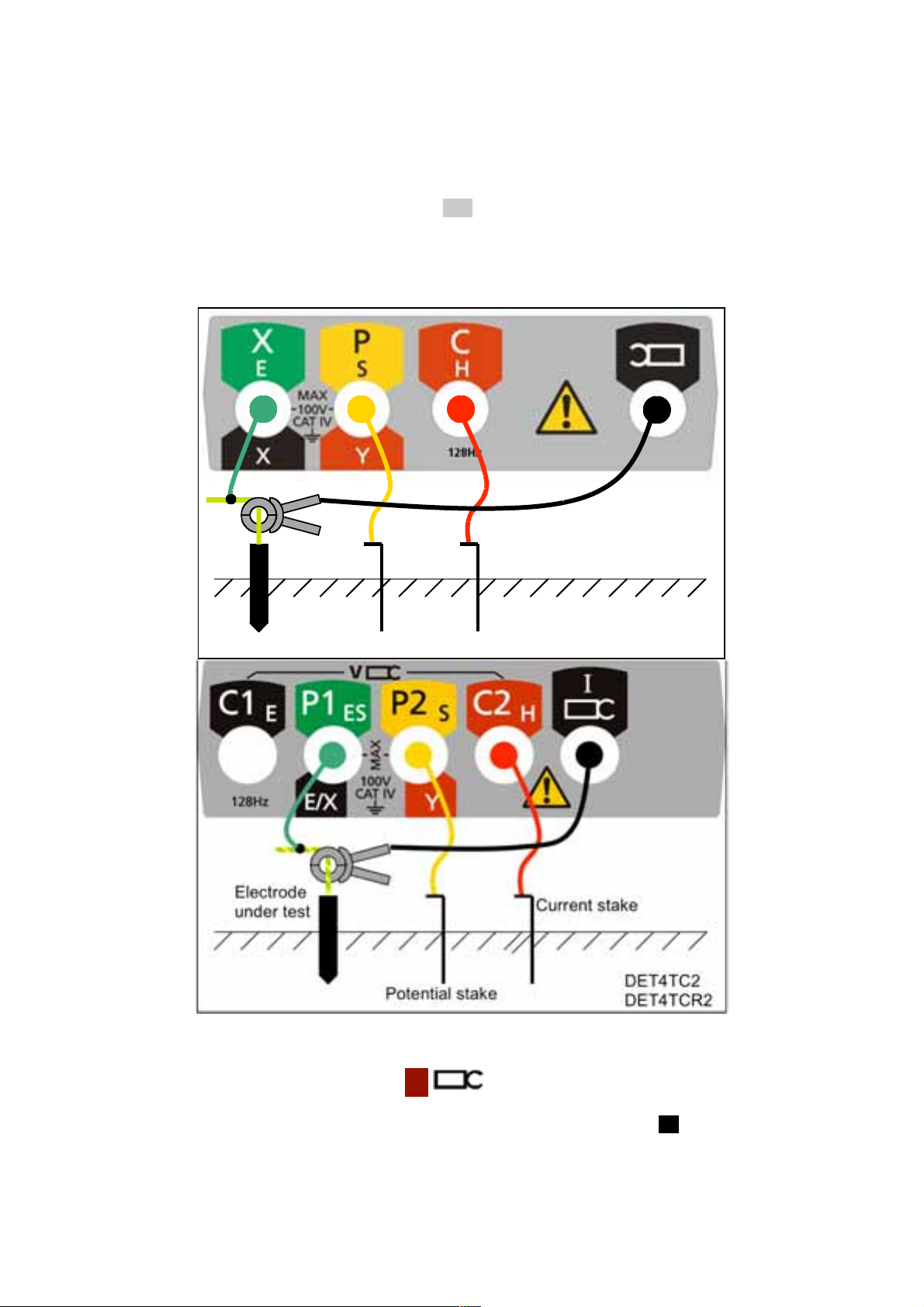
Three-terminal resistance measurement using ART (DET3TC, DET4TC2
and DET4TCR2)
Before making a measurement using ART, please follow the procedure contained in the section on
ICLAMP calibration.
1. Ensure the rotary selector switch is in the OFF position.
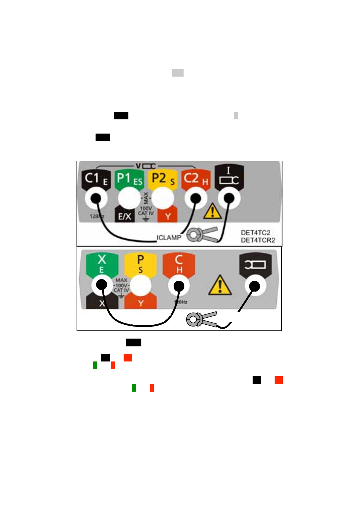
2. Connect the instrument as shown in Figure 31.
Figure 31: instrument connection for measuring three-terminal resistance using ART
Electrode
under test
Potential stake
Current stake
DET3TC
3. Close the ICLAMP around the conductor under test.
4. Set the rotary selector switch to the 3P position.
5. DET4TC2 and DET4TCR2 only: Select the desired test frequency using the Hz button
49
Page 50

6. Press and release the TEST button [by holding the TEST button, the resistance measurement will
be continually updated].
7. The instrument will perform pre-measurement checks, the status of which will be indicated on
the display.
8. The three-terminal resistance reading using ART will be displayed as shown in Figure 32.
Figure 32: example three-terminal resistance reading using ART
(DET4 display shown)
9. Under certain circumstances, the instrument may display a noise warning as shown:
This means that interference has been detected which may impair the accuracy of the measurement. In
particular, the reading could be lower than the actual resistance. The resistance of the electrode or system
must be verified by an alternative method.
50
Page 51

Note:
The instrument will display the warning triangle and an excessive noise voltage indicator if the ground
noise voltage is above 40 V pk-pk (14 Vrms).
The instrument will display the warning triangle and a voltage over-range condition if the ground
noise voltage is above 100 V – no resistance reading is possible under this condition.
The instrument will display the warning triangle above 2 A – no ART testing is possible under this
condition.
The instrument will display the warning triangle and an over-range condition above 20 A – no ART
testing is possible under this condition.
Ensure that the ICLAMP jaw mating surfaces are free of dust and contamination and that they contact
completely when the ICLAMP is closed.
Currents carried by conductors in close proximity to the ICLAMP may affect calibration and reduce the
accuracy of measurements made.
51
Page 52
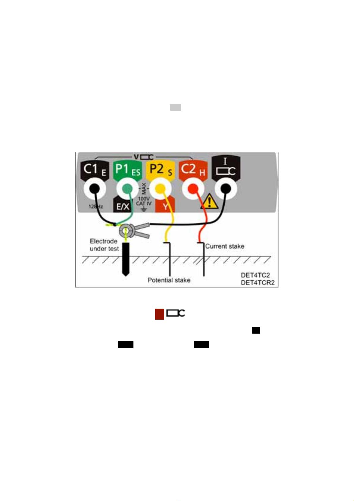
Three-terminal resistance measurement with lead-null using ART
4P
TEST
TEST
(DET4TC2 and DET4TCR2)
In certain circumstances, the resistance of the test leads connecting to the electrode under test may itself
form a significant part of the measurement electrode resistance. This effect can be eliminated using the
lead-null technique described in this section.
Before making a measurement using ART, please follow the procedure contained in the section on
ICLAMP calibration.
1. Ensure the rotary selector switch is in the OFF position.
2. Connect the instrument as shown in Figure 33.
Figure 33: instrument connection for measuring three-terminal resistance
with lead-null using ART
3. Close the ICLAMP around the conductor under test.
4. Set the rotary selector switch to the
5. DET4TC2 and DET4TCR2 only: Select the desired test frequency using the Hz button.
6. Press and release the
will be continually updated].
7. The instrument will perform pre-measurement checks, the status of which will be indicated on
the display.
8. The three-terminal resistance reading with lead-null using ART will be displayed as shown in
Figure 34.
button [by holding the
position.
button, the resistance measurement
52
Page 53
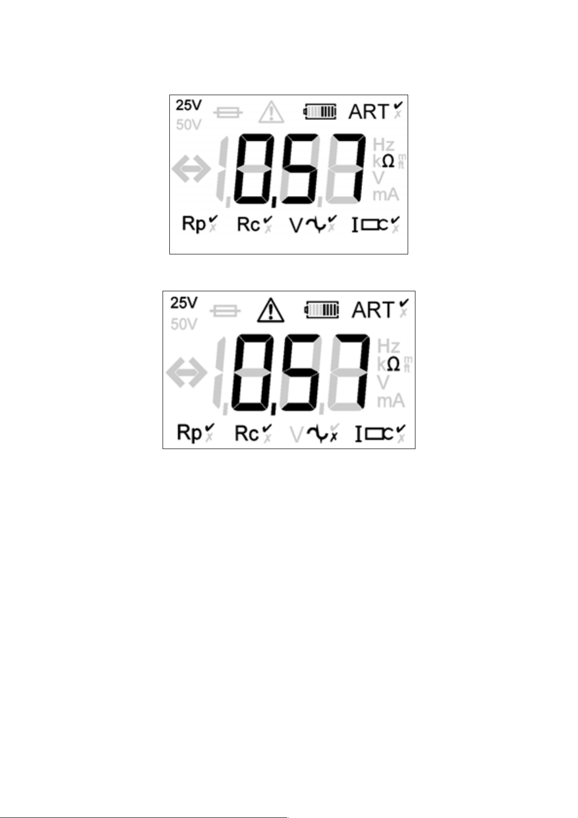
Figure 34: example three-terminal resistance reading with lead-null using ART (DET4
display shown)
8. Under certain circumstances, the instrument may display a noise warning as shown:
This means that interference has been detected which may impair the accuracy of the measurement. In
particular, the reading could be lower than the actual resistance. The resistance of the electrode or system
must be verified by an alternative method.
Note:
The instrument will display the warning triangle and an excessive noise voltage indicator if the ground
noise voltage is above 40 V pk-pk (14 Vrms).
The instrument will display the warning triangle and a voltage over-range condition if the ground
noise voltage is above 100 V – no resistance reading is possible under this condition.
The instrument will display the warning triangle above 2 A – no ART testing is possible under this
condition.
The instrument will display the warning triangle and an over-range condition above 20 A – no ART
testing is possible under this condition.
Ensure that the ICLAMP jaw mating surfaces are free of dust and contamination and that they contact
completely when the ICLAMP is closed.
Currents carried by conductors in close proximity to the ICLAMP may affect calibration and reduce the
accuracy of measurements made.
53
Page 54
Two-clamp stakeless measurement (DET4TC2 and DET4TCR2)
Before making a stakeless measurement, please follow the procedures contained in the sections on
ICLAMP calibration.
1. Ensure the rotary selector switch is in the OFF position.
2. Connect the instrument as shown in Figure 35.
Figure 35: instrument connection for two-clamp stakeless measurement
3. Close the ICLAMP around the conductor under test. Ensure the arrow on the side of the jaw is
pointing in the same direction as the arrow on the VCLAMP.
4. Close the VCLAMP around the conductor under test. Ensure the arrow on the side of the jaw is
pointing in the same direction as the arrow on the ICLAMP.
5. Ensure a minimum separation of 100mm between the ICLAMP and VCLAMP.
6. Set the rotary selector switch to the
7. DET4TC2 and DET4TCR2 only: Select the desired test frequency using the Hz button.
8. Press and release the TEST button [by holding the TEST button, the resistance measurement will
be continually updated].
9. The instrument will perform pre-measurement checks, the status of which will be indicated on
the display.
10. The stakeless resistance reading will be displayed as shown in Figure 36.
position.
54
Page 55

Figure 36: example resistance reading using two-clamp stakeless method
TEST
11. Under certain circumstances, the instrument may display a noise warning as shown:
This means that interference has been detected which may impair the accuracy of the measurement. In
particular, the reading could be lower than the actual resistance. The resistance of the electrode or system
must be verified by an alternative method.
Note:
The instrument will display the warning triangle above 2 A – no “Stakeless” testing is possible under
this condition.
The instrument will display the warning triangle and an over-range condition above 20 A – no
“Stakeless” testing is possible under this condition.
Ensure that the VCLAMP and ICLAMP jaw mating surfaces are free of dust and contamination and that
they contact completely when the VCLAMP and ICLAMP are closed.
Currents carried by conductors in close proximity to the VCLAMP and ICLAMP may affect calibration
and reduce the accuracy of measurements made.
If the VCLAMP opens at any time after the
button is pressed, the test will be aborted.
55
Page 56
ICLAMP calibration (DET3TC, DET4TC2 and DET4TCR2)
The ICLAMP should be calibrated once at each test site to take into account the effects of transportation,
temperature and humidity on the ICLAMP.
1. Ensure the rotary selector switch is in the OFF position.
2. Connect the instrument as shown in Figure 37.
3. Ensure that the ICLAMP is not clamped around a conductor.
4. Press and hold the TEST button and switch instrument ON to the A setting using the selector
switch.
5. Release the TEST button.
Figure 37: ICLAMP zero calibration
ICLAMP
DET3TC
6. Press and release the TEST button until a “0” reading is obtained on the display.
7. Connect the C1 and C2 terminals together using the calibration lead supplied with the
ICLAMP. [X and C terminals for DET3TC]
8. Close the ICLAMP around the calibration lead, which connects the C1 and C2 terminals
as shown in Figure 38. [X and C terminals for DET3TC]
56
Page 57
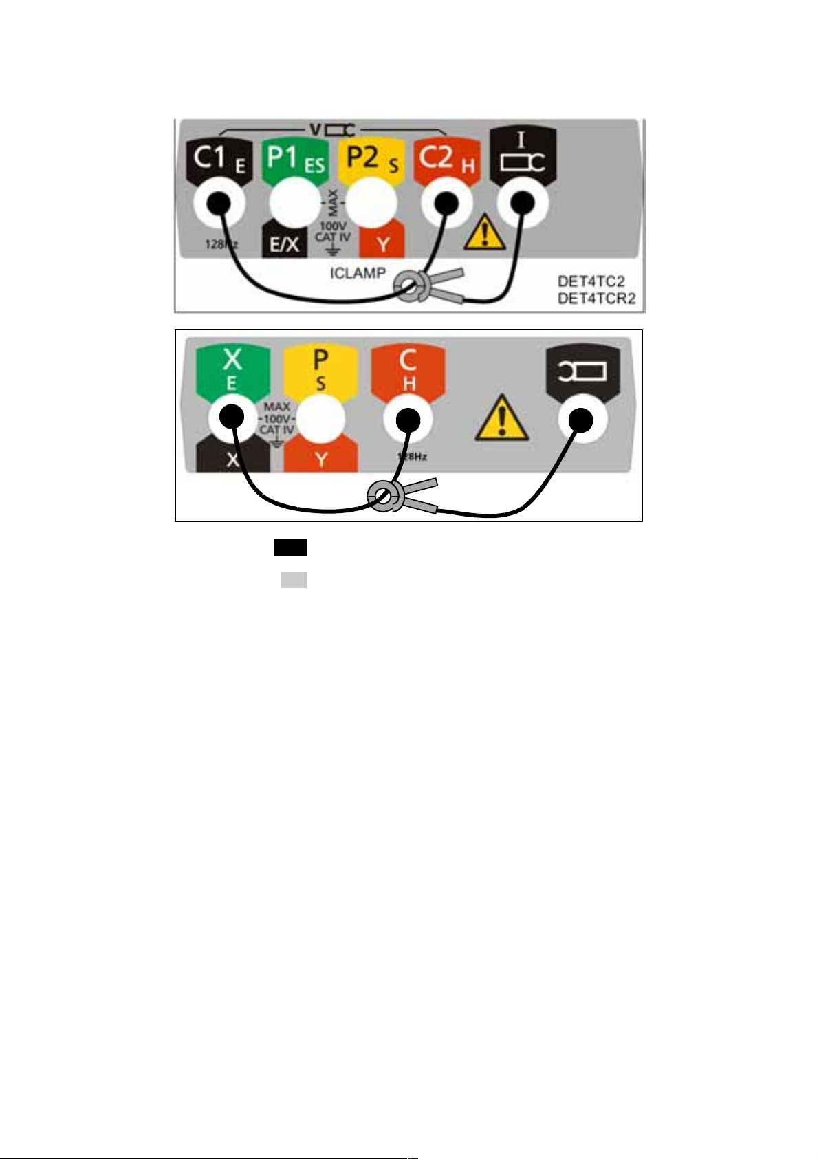
Figure 38: ICLAMP 100% calibration
ICLAMP
DET3TC
9. Press and release the TEST button until a “100” reading is obtained on the display.
10. Switch the instrument OFF using the selector switch.
11. The instrument is now calibrated to the ICLAMP and the calibration stored in non-volatile
memory.
57
Page 58

OPERATION OF THE TWO-CLAMP CALIBRATION ADAPTOR
1. Ensure the rotary selector switch is in the OFF position.
2. Connect the instrument as shown.
3. Close the ICLAMP around one loop of the two-clamp calibration adaptor.
4. Close the VCLAMP around the other loop of the two-clamp calibration adaptor.
5. Ensure a minimum separation of 100mm between the ICLAMP and VCLAMP.
6. Set the rotary selector switch to the
position.
7. Press and release the TEST button [by holding the TEST button, the resistance
measurement will be continually updated].
8. The instrument will perform pre-measurement checks, the status of which will be indicated on
the display.
9. The two-clamp resistance reading will be displayed and should match the value written on the
two-clamp calibration adaptor.
Note:
1. Ensure that the ICLAMP and VCLAMP jaw mating surfaces are free of dust and contamination
and that they contact completely when the units are closed.
2. Currents carried by conductors in close proximity to the ICLAMP may affect calibration and
reduce the accuracy of measurements made.
58
Page 59

OPERATION OF THE CALIBRATION ADAPTOR
1. Ensure the rotary selector switch is in the OFF position.
2. Connect the instrument as shown.
CALIBRATION
ADAPTOR
3. Set the rotary selector switch to the 2P, 3P or 4P position.
4. Press and release the TEST button [by holding the TEST button, the resistance measurement will
be continually updated].
5. The instrument will perform pre-measurement checks, the status of which will be indicated on
the display.
6. The resistance reading will be displayed and should match the value written on the calibration
adaptor.
59
Page 60

PREVENTIVE INSTRUMENT MAINTENANCE
1. The DET series instruments require very little maintenance.
2. Test leads should be checked before use to ensure there is no damage.
3. Ensure batteries are removed if left unused for extended periods.
4. When necessary, the instrument can be cleaned with a damp cloth.
5. Do not use alcohol-based cleaners, as these may leave a residue.
60
Page 61

TECHNICAL SPECIFICATION DET3Tx & DET4Tx
Only values with tolerance or limits are guaranteed data. Parameters without tolerances are for
information only.
Ingress protection:
IP54
C stake, P stake and Noise check:
Automatic
Noise rejection:
40 V pk to pk (14 V rms)
2-wire, 3-wire, 4-wire test:
Yes, no shorting links required
No disconnect testing (ART):
Yes, with ICLAMP
Stakeless measurement:
Yes, with ICLAMP and VCLAMP
Instrument output:
Voltage: ±25 V or ±50 V at 128Hz (DET3TA,
DET3TC, DET3TD, DET4TD2 and DET4TR2)
Resistance accuracy:
2P measurements: 2% ±3 digits
3P measurements: 2% ±3 digits
4P measurements: 2% ±3 digits
ART measurements: 5% ±3 digits
Stakeless measurements: 7% ±3 digits
Maximum probe resistance:
Rp limit: 100 k (5 0 V output voltage)
Rc limit: 100 k (50 V output voltage)
Limits reduced to 50 k for 25 V output voltage
Limits reduced to 5 k for 0.01 resolution
Display:
3½ digit high contrast liquid crystal, backlit
Battery type:
DET3TA, DET3TC, DET3TD, DET4TD2, DET4TC2 8 off AA (LR6) dry cells
DET4TCR2, DET4TR2 – 8 off AA (LR6) NiMH
rechargeable cells
Voltage:
±25V or ±50V at 94Hz, 105Hz, 111Hz and 128Hz
(DET4TC2 and DET4TCR2)
Current:
4.5 mA or 0.45mA (DET3TA, DET3TC, DET3TD,
DET4TD2 and DET4TR2)
Current:
4.5 mA or 0.45mA and 0.045 mA (DET4TC2 and
DET4TCR2)
Ground current range with clamp:
0.5 mA to 19.9 A
Ground current accuracy:
5% ±3 digits
Ground voltage range:
0 to 100 Vac
Ground voltage accuracy:
2% ±2 V
Resistance range:
0.01 to 2 k (DET3TA, DET3TC, DET3TD)
0.01 to 20 k (DET4TD2 and DET4TR2)
0.01 to 200 k (DET4TC2 and DET4TCR2)
Operating temperature range:
-15°C to +55°C / 5°F to 131°F
Storage temperature range:
-40°C to +70°C / -40°F to 158°F
Safety
Complies with the requirements of IEC61010-1
100V CAT IV between terminal pairs.
EMC
In accordance with IEC61326-1
Operational uncertainties
Refer to www.megger.com
Standards compliance
Complies with the requirements of KEMA K85B
Complies with the following parts of EN61557,
Electrical safety in low voltage distribution systems
up to 1000 V a.c. and 1500 V d.c. – Equipment for
testing, measuring or monitoring of protective
measures”.
Part 1 – General requirements
Part 5 – Resistance to earth
Dimensions:
203mm x 148mm x 78mm / 8in x 5.8in x 3in
Weight:
1 kg / 2.2 lb
61
Page 62

ICLAMP SPECIFICATIONS
Measurement range: 1 mA to 1200 A
Transformation ratio: 1000 : 1
Output signal: 1 mA / A (1 A @ 1000 A)
Accuracy
1mA to 100 mA : 3% of reading
0.1 A to 1 A : 2% of reading
1 A to 10 A : 1% of reading
10 A to 100 A : 0.5% of reading
Operating temperature
-10°C to +50°C / 14°F to 122°F
0% to 85% RH at +35°C / 95°F
Storage temperature
-20°C to +70°C / -4°F to 158°F
Jaw opening: 57 mm maximum (2.3 in)
Maximum conductor size: 52 mm (2.1 in)
Insulation: Double insulation
Voltage rating:
Current rating: 1200 A for 20 minutes
Ingress protection: IP40
600 V CAT III
VCLAMP SPECIFICATIONS
Insulation: Double insulation
Voltage rating: 600V CAT III
Current rating: 1200A for 20 minutes
Ingress protection: IP40
Operating temperature
-10°C to +50°C / 14°F to 122°F
0% to 85% RH at +35°C / 95°F
Storage temperature
-20°C to +70°C / -4°F to 158°F
Jaw opening: 57mm maximum (2.3in)
Maximum conductor size: 52mm / 2.1in
Electrical safety
IEC61010-2-032
EMC
IEC61326-1
Dimensions: 111mm x 216mm x 45mm
(4.4in x 8.5in x 1.8in)
Safety
IEC61010-2-032
EMC
IEC61326-1
Dimensions:
111 mm x 216 mm x 45 mm (4.4 in x 8.5
in x 1.8 in)
Weight: 0.5 kg approximately (1.2lb)
Weight: 0.5 kg approximately (1.2 lb)
62
Page 63

CALIBRATION ADAPTOR
ELECTRICAL SPECIFICATION
Value: 25 ± 0.1%
MECHANICAL SPECIFICATION
Operating temperature
-10°C to +50°C / 14°F to 122°F
0% to 85% RH at +35°C / 95°F
Storage temperature
-20°C to +70°C (-4°F to 158°F)
Dimensions: 60mm x 55mm x 25mm (2.5in x 2.25in x 1in)
Weight: 0.1 kg approximately (0.2 lb)
TWO-CLAMP CALIBRATION ADAPTOR
ELECTRICAL SPECIFICATION
Value: 25 ± 1%
MECHANICAL SPECIFICATION
Operating temperature
-10°C to +50°C (14°F to 122°F)
0% to 85% RH at +35°C / 95°F
Storage temperature
-20°C to +70°C (-4°F to 158°F)
Dimensions:
111mm x 216mm x 45mm (4.4in x 8.5in x 1.8in)
Weight:
0.1 kg approximately (0.2 lb)
63
Page 64

REPAIR AND WARRANTY
The instrument contains static sensitive devices, and care must be taken in handling the printed circuit board. If an
instrument’s protection has been impaired it should not be used, but sent for repair by suitably trained and qualified
personnel. The protection is likely to be impaired if for example, it shows visible damage, fails to perform the
intended measurements, has been subjected to prolonged storage under unfavourable conditions, or has been
subjected to severe transport stresses.
NEW INSTRUMENTS ARE GUARANTEED FOR 1 YEAR FROM THE
Note: Any unauthorized prior repair or adjustment will automatically invalidate the Warranty.
CALIBRATION, REPAIR AND SPARE PARTS
For service requirements for Megger Instruments contact:
Megger Limited or Megger
Archcliffe Road Valley Forge Corporate Centre
Dover 2621 Van Buren Avenue
Kent CT17 9EN Norristown PA 19403
England. U.S.A.
Tel: +44 (0) 1304 502 243 Tel: +1 610 676 8579
Fax: +44 (0) 1304 207 342 Fax: +1 610 676 8625
Megger operate fully traceable calibration and repair facilities, ensuring your instrument continues to provide the high
standard of performance and workmanship you expect. These facilities are complemented by a worldwide network of
approved repair and calibration companies, which offer excellent in-service care for your Megger products.
Returning your product to Megger - UK and USA service centres
1. When an instrument requires recalibration, or in the event of a repair being necessary, a Returns
Authorisation (RA) number must first be obtained from one of the addresses shown above. You will be asked
to provide the following information to enable the Service Department to prepare in advance for receipt of
your instrument, and to provide the best possible service to you.
Model, e.g. DET4TC2.
Serial number, to be found on the underside of the case or on the calibration certificate.
Reason for return, e.g. calibration required, or repair.
Details of the fault if the instrument is to be repaired.
2. Make a note of the RA number. A returns label can be emailed or faxed to you if you wish.
3. Pack the instrument carefully to prevent damage in transit.
4. Ensure the returns label is attached, or that the RA number is clearly marked on the outside of the package
and on any correspondence, before sending the instrument, freight paid, to Megger. Copies of the original
purchase invoice and packing note should be sent simultaneously by airmail to expedite clearance through
customs. In the case of instruments requiring repair outside the warranty period, an immediate quotation
can be provided when obtaining the RA number.
5. You may track the progress of your return on line at www.megger.com
Approved Service Centres
A list of Approved Service Centres may be obtained from the UK address above, or from Megger’s website at
www.megger.com
DATE OF PURCHASE BY THE USER.
64
Page 65

M
Megger Limited
Archcliffe Road, Dover
Kent CT17 9EN England
T +44 (0)1 304 502101
F +44 (0)1 304 207342
E uksales@megger.com
Megger
4271 Bronze Way, Dallas,
Texas 75237-1019 USA
T +1 800 723 2861 (USA ONLY)
T +1 214 333 3201
F +1 214 331 7399
E ussales@megger.com
Megger
Z.A. Du Buisson de la Couldre
23 rue Eugène Henaff
78190 TRAPPES France
T +33 (0)1 30.16.08.90
F +33 (0)1 34.61.23.77
E infos@megger.com
Megger Pty Limited
Unit 26 9 Hudson Avenue
Castle Hill
Sydney NSW 2125 Australia
T +61 (0)2 9659 2005
F +61 (0)2 9659 2201
E ausales@megger.com
Megger Limited
110 Milner Avenue Unit 1
Scarborough Ontario M1S 3R2
Canada
T +1 416 298 9688 (Canada only)
T +1 416 298 6770
F +1 416 298 0848
E casales@megger.com
Megger products are distributed in 146 countries worldwide.
This instrument is manufactured in the United Kingdom.
The company reserves the right to change the specification or design without prior notice.
Megger is a registered trademark
Part No. DET4TC_UG_en_V05 1108
www.megger.com
65
 Loading...