

Page 1
NEW PRODUCT LAUNCH
Sales guide
MMeeggggeerr DDEETT44TTCC aanndd DDEETT44TTCCRR
22,,33 aanndd 44 PPoollee EEaarrtthh TTeesstteerrss
The latest additions to the DET Earth testing range.
Providing a solution to every
earth testing challenge
Megger Limited PWS / Nov 06
DET4TC/R launch
Page 2

2
Table of Contents
PRODUCT FAMILY .......................................................................3
DET4TC/R Selection Chart........................................................... 3
NEW – Professional Earth Testing Kit........................................ 4
THIS PRODUCT IS USED FOR? ..................................................5
WHY?............................................................................................. 5
THIS PRODUCT IS USED BY? ..................................................... 6
TECHNICAL OVERVIEW ..............................................................7
Principle of Operation .................................................................. 8
FEATURES, ADVANTAGES AND BENEFITS ........................... 10
ORDERING INFORMATION........................................................ 11
COMPETITOR ANALYSIS ..........................................................11
DET4TC/R Verses Fluke 1623 ...............................................................................12
DET4TC/R Verses Fluke 1625 ...............................................................................13
DET4TC/R verses Metrel M2124C.........................................................................14
Appendix A.................................................................................. 15
Application Guide .................................................................................15
The “ART” of earth electrode testing ............................................15
Just a little aside ..........................................................................................16
Megger gets down to earth with “ART”...............................................16
Don’t underestimate the power of “ART” ...........................................18
The problem with Spheres of Influence..............................................19
We all like “ART” but sometimes it’s misunderstood ....................21
Some resistance to ART ..........................................................................22
The Best Application of “ART” ...............................................................22
“STAKELESS” Earth Electrode Testing .....................................23
Incorrect use of Stakeless testing.........................................................25
The Best Application of “Stakeless” testing......................................26
Megger Limited PWS / Nov 06
DET4TC/R Launch
Page 3
3
PRODUCT FAMILY
The new products are additions to the DET3 and 4 contractor series of earth testers,
launched about a year ago.
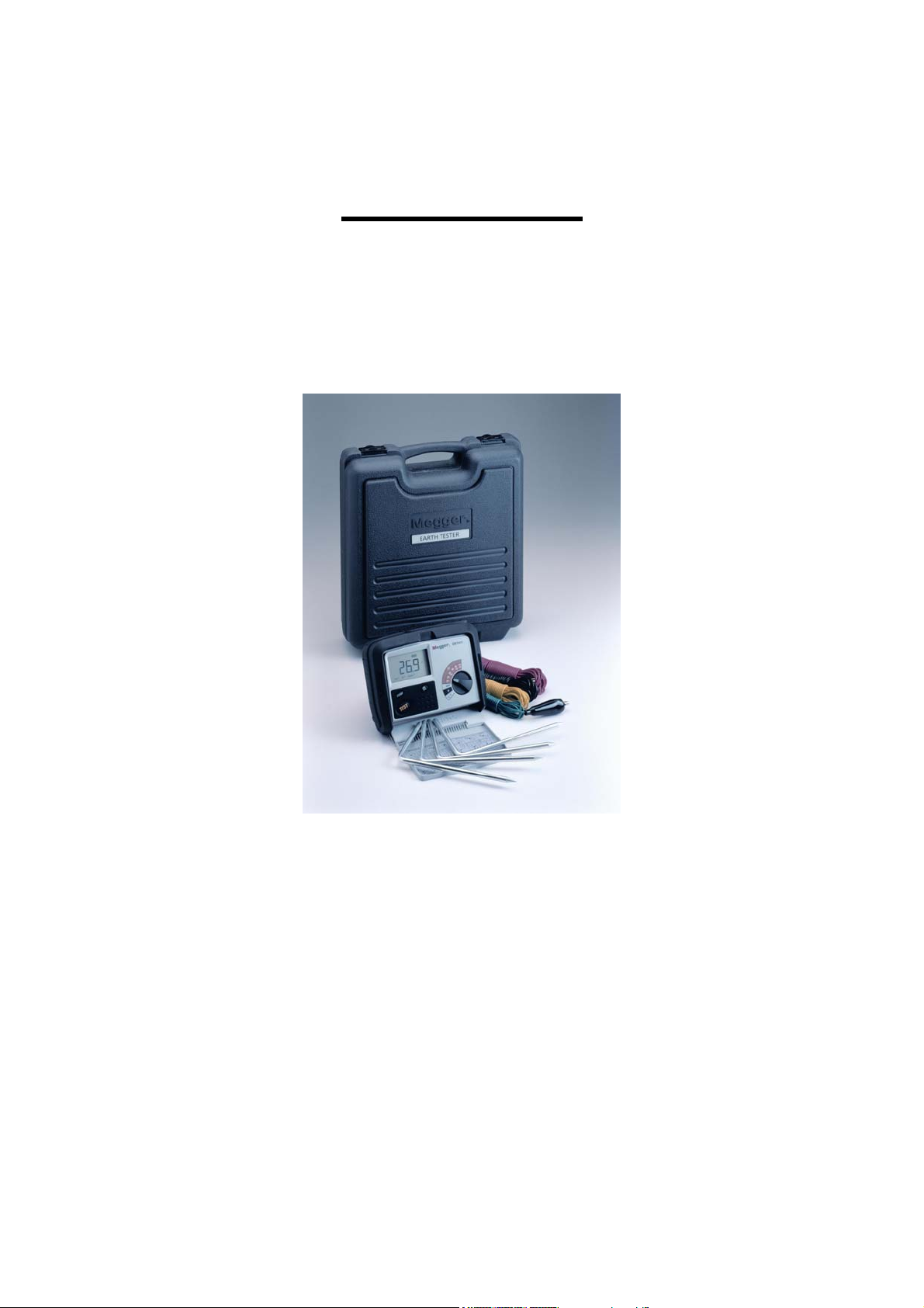
The instruments utilises the same rubber armoured, IP54 rated case as the DET3
and is supplied in a tough blow moulded case together with test leads and spikes.
The structure of the new instruments is as follows:
DET4TC 2, 3 & 4 pole earth testers with ART and Stakeless testing
capability
DET4TCR 2, 3 & 4 pole, rechargeable, earth testers with ART and
Stakeless testing capability.
DET4TC+Kit 2, 3 & 4 pole earth testers with ART and Stakeless testing,
complete with ICLAMP and VCLAMP.
DET4TCR+Kit 2, 3 & 4 pole, rechargeable, earth testers with ART and
Stakeless testing, complete with ICLAMP and VCLAMP.
The new DET4 range replaces the complete DET5/4 range, which has an intended
obsolescence date of 30
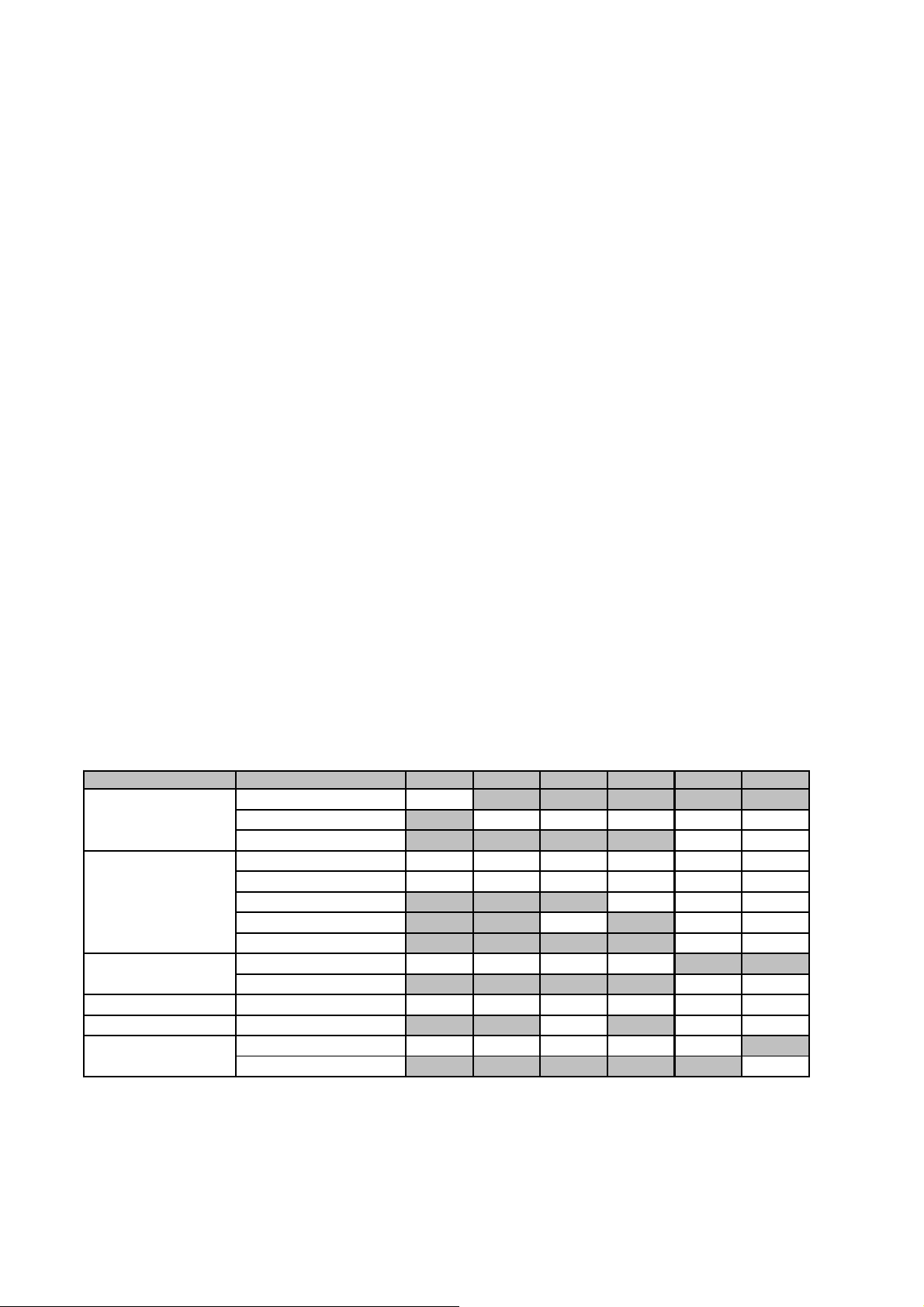
The complete contractor series of Earth testers can now be summarised by the
following chart:
DET4TC/R Selection Chart
Feature Sub-feature DET3TADET3TD DET3TC DET4TD DET4TC DET4TCR
Display Analog
Earth Tests 2 Pole
Earth Resistance Range 0.01 to 2kΩ
Earth Voltage Range 0-100V
Earth Current Range 0.5mA to 19.9A
Supply Alkaline batteries
Digital
Back light
3 Pole (Fall of potential)
4 Pole (Soil resistivity)
Selective (ART) capability
Stakeless (2 clamps)
0.01 to 20kΩ
Rechargeable batteries
Where does the name come from?
D E T 4T C R
Digital Earth Tester 4 Terminal Clamp Rechargeable
th
June 2007.
✔
✔✔✔✔✔
✔✔
✔✔✔✔✔✔
✔✔✔✔✔✔
✔✔✔
✔✔✔
✔✔
✔✔✔✔
✔✔
✔✔✔✔✔✔
✔✔✔
✔✔✔✔✔
✔
Megger Limited PWS / Nov 06
DET4TC/R Launch
Page 4
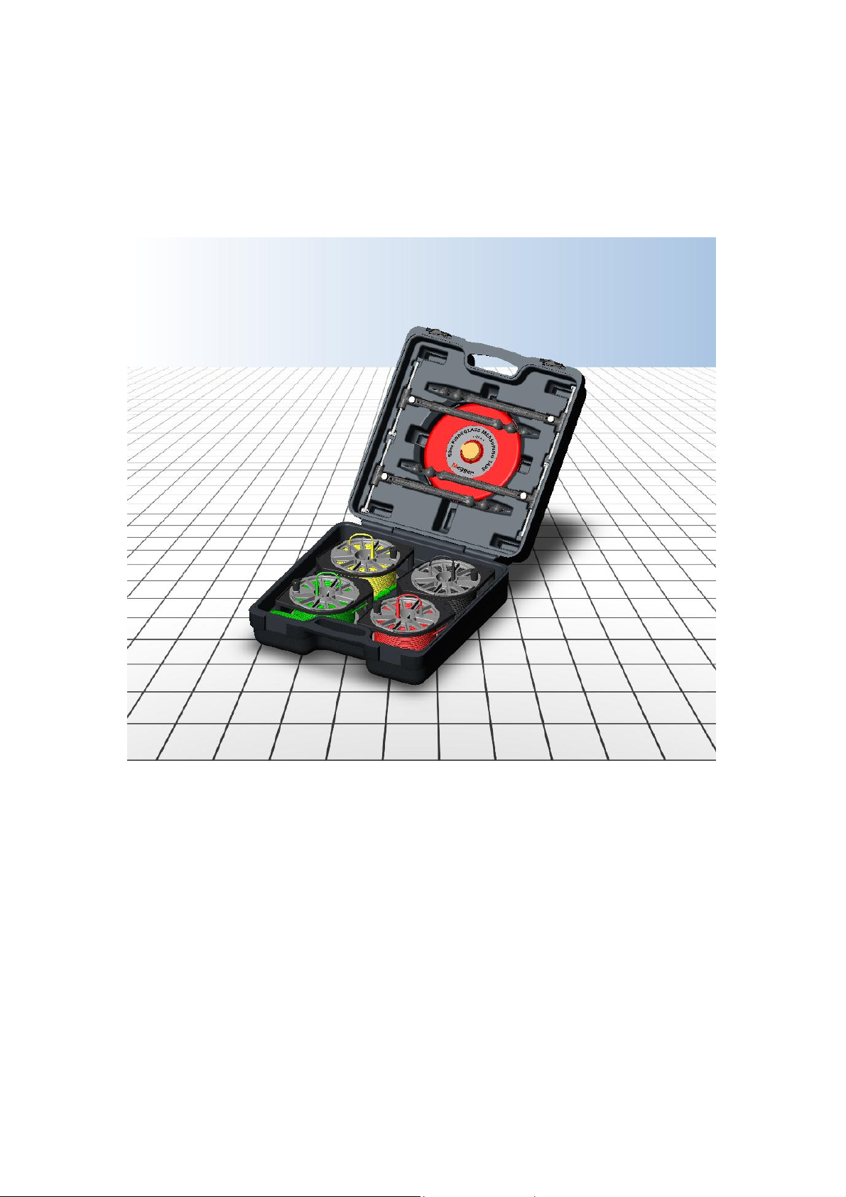
NEW – Professional Earth Testing Kit
To complement the launch of the new DET4TC/R a new Professional Earth Testing
Kit will be available shortly.
4
The new kit is innovative, high quality and comes supplied in a tough hard carry case
similar to the instrument carry case.
The kit consist of the following:
• Four twist in auger style test spikes
• Four test leads (2 x 50m, 2 x 30m)
o Supplied on four reels with test lead wind in while mounted on test
spike feature.
o Reels have innovative test lead brushing feature to clean while
winding in.
• Tape measure
Kit part number: 6320-245
Megger Limited PWS / Nov 06
DET4TC/R Launch
Page 5

5
THIS PRODUCT (DET4TC/R) IS USED FOR?
This product is used for both soil resistivity testing (4 pole) and earth electrode (2 and
3 pole) testing. Methods such as ART allow earth electrodes to be tested without
disconnection. The addition of Stakeless testing will allow testing of electrode where
the use of test stakes is impractical.
WHY?
• Soil resistivity testing. (4 pole)
o Used to locate the best lowest resistance location for a new earth
system.
o Obtain earth resistance values required to design the earth system
o Geophysics – locating changes in geology
• Earth Electrode testing (2, 3 pole)
o Earth electrode / system resistance must be low and reliable. Why?
• To ensure enough current to flow in fault conditions to ensure
the circuits’ protective device trips out in time. Failure to trip or
trip too slowly can result in expensive damage to equipment,
fire or serious injury.
• Lightning strike protection.
• Improve equipment performance by reducing noise levels.
• Static electricity dissipation.
• Prevent dangerously high step or contact voltages present
during fault or high load conditions, another safety issue.
o Earth systems require testing both immediately after installation, and
at regular intervals thereafter as part of a maintenance program.
• ART – Attached Rod Technique
o This method is an additional feature used when performing the
standard 3 pole method when testing earth electrode resistance.
o The main problem associated with testing an electrode resistance is
the requirement to disconnect it. This is because the test current from
the instrument will flow, not just down the electrode being tested, but
also through any other parallel paths. E.g. other electrodes in the
system or back through the building earth.
• ART uses a clamp to measure only the current flowing down
the electrode being tested; the instrument then uses this
measurement to calculate the resistance of electrode.
Megger Limited PWS / Nov 06
DET4TC/R Launch
Page 6

6
• Stakeless Test – Look no test spikes!
o Although the 3-pole method is the traditional method of test earth
electrode resistance, it relies on driving auxiliary test spikes into the
ground, which is not always practical. Imagine trying to drive spikes in
inner city concrete jungles, and locations such as cable cellars
beneath sub stations.
o Another ideal application for this test is measuring electrode
resistance on lightning protection system on buildings.
• The stakeless method utilises two clamps. One to induces
current into the circuit the other the measure the resulting
amount.
• The measurement taken is the resistance of a loop, including
that of the electrode under test.
• The reading will not directly compare to the 3-pole method due
to the additional elements in the reading. However the
readings will always be optimistic and should be repeatable,
ideal for monitoring the earth electrode condition over time.
• Stakeless measurements made in 4-pole mode allow all test
lead resistances to be ignored.
In summary, with the addition of ART and Stakeless testing, DET4TC/R is an
excellent replacement for the DET5/4. The DET4TC/R provides real additional
benefits to the customer in terms of ease of use and the ability to take measurements
in situations the DET5/4 cannot.
Provided with this sales guide in appendix A, is a applications note giving detailed
information on how to use ART and Stakeless testing. This will give valuable
assistance to customers, allowing them to fully understand and get the most from
these test methods.
Further, more detailed information on earth testing may be found on the Megger
Earth/ground micro site. http://www.megger.com/us/story/Index.php?ID=125
THIS PRODUCT IS USED BY?
• Electrical contractors,
• Utilities, Maintenance
• Railways
• Repair Organisations (Industrials),
• Telecoms and Datacoms installers.
• Specialist grounding/earthing companies and consultants.
• Petro-chemical companies
• Service providers
Megger Limited PWS / Nov 06
DET4TC/R Launch
Page 7

TECHNICAL OVERVIEW
7
Megger Limited PWS / Nov 06
DET4TC/R Launch
Page 8
8
DET4TCR
The instrument and display layout are identical with the exception of the 12V input for
battery charging.
Principle of Operation
The principal of operation is fully described in the User Guide, a copy of which has
been provided as part of the launch pack. However since the DET4TCR is replacing
the DET5/4, just the pertinent parts covering the additional ART and Stakeless
capabilities have been reproduced in this document.
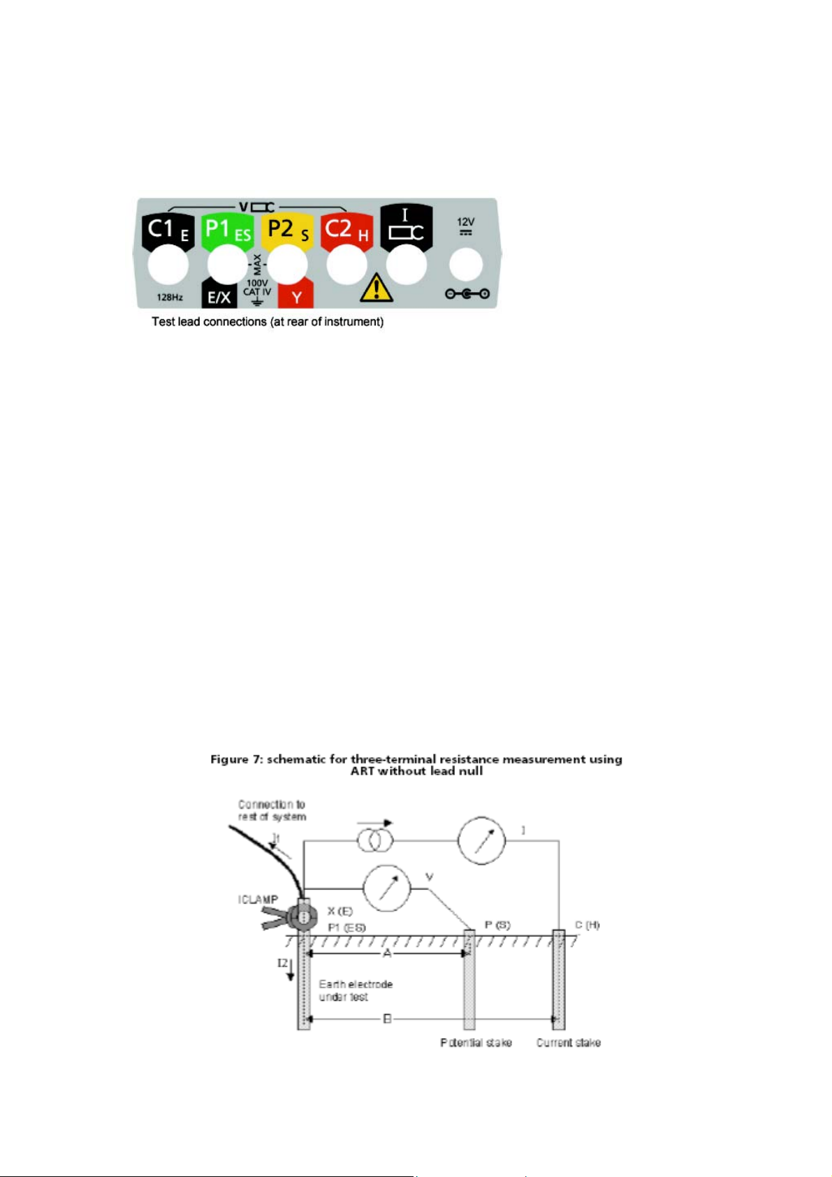
Principle of operation (three-terminal resistance measurement using
ART)
The classic three-terminal test method has a disadvantage, namely that the electrode
under test must be disconnected from the system it is supposed to protect in the
event of a power system fault. The reason for this is that the injected test current will
take all possible routes to ground and not all of it will necessarily flow through the
electrode under test. In this case, the instrument will make a reading
of the entire earthing network, not just the individual electrode.
By using a current transducer (the Megger ICLAMP) to measure the current flowing
through the electrode under test as a fraction of the total test current injected, the
instrument can determine the individual resistance. This arrangement is shown in
Figure 7.
Megger Limited PWS / Nov 06
DET4TC/R Launch
Page 9

In this configuration, the injected test current I splits along two paths into I1 (flowing
into the connected earthing system) and I2 (flowing into the electrode under test, i.e.
I=I1+I2. The resistance of the electrode under test is calculated as R=V/I2 or R=V/(II1). The current transducer (ICLAMP) measures I2 and feeds this value back to the
instrument.
Principle of operation (two-clamp stakeless resistance measurement)
In this example, the electrode under test is connected to a network of other
electrodes. It is either impractical or unsafe to disconnect an individual electrode for
testing. Also, there might be insufficient space to perform a classic three-terminal
resistance measurement. The stakeless test method using both VCLAMP and
ICLAMP can be used to obtain a measurement for the electrode under test.
A defined test voltage is injected into the system using the VCLAMP, inducing a
current, I, to flow and be measured by the ICLAMP. The model shown in Figure 8
can be simplified to the resistance of the electrode under test, Rx and the resistance
of the other electrodes in parallel, i.e. R1 || R2 || … || Rn. Therefore, the current
induced by the test voltage is I=V/[Rx+(R1 || R2 || … || Rn)]. It follows that as the
resistance of the other electrodes in parallel approaches zero, then the resistance
measured, approaches the value of the electrode under test.
9
Megger Limited PWS / Nov 06
DET4TC/R Launch
Page 10

10
FEATURES, ADVANTAGES AND BENEFITS
DET4TC/R
F: Tough rubber armoured IP54 rated instrument case.
A: Case can withstand knocks, and the outdoor environments experienced when
earth testing.
B: Instrument will last a long time, and will be ready to test when required.
----------------------------------------
F: Supplied in tough blow moulded carry case.
A: Keeps instrument, test leads, spikes, and optional clamps together and
protected.
B: Helps prevent loss of accessories, also makes ideal ‘tray’ to put the
instrument on when testing. Saves having to lay the instrument directly onto
muddy ground.
----------------------------------------
F: Supplied with calibration certificate, test leads and spike kit.
A: Nothing more to buy to start testing.
B: Saves time having to source separate leads and spikes. No waiting for
calibration to be carried out. No hidden costs. Convenient.
----------------------------------------
F: Back light
A: Easy to read in low light environments
B: Easier to operate when not having to use a torch to be able to read the
display.
----------------------------------------
F: ‘Attached Rod Technique’ capability, ART.
A: With the addition of an ICLAMP the instrument is able to take 3 or 4 pole
measurements of earth electrodes without disconnecting them.
B: Saves both time and aggravation having to undo rusted connections. No need
to shut down supply to ensure safety.
----------------------------------------
F: ‘Stakeless’ testing capability.
A: No need to drive test spikes in ground to perform measurement.
B: Allows testing in areas when driving test spike is impossible. E.g. Sub station
cable cellars, or when testing lightning protection in concreted locations.
----------------------------------------
F: One button operation with automatic noise check and automatic P and C
spike resistance check.
A: Easy to operate.
B: Little time required learning operation, and time saved not having to spend
considerable time troubleshooting poor connections etc.
----------------------------------------
F: User selectable output voltage – 25V or 50V
A: 25V required for testing agricultural environments
B: The ability to test in agricultural locations as per IEC61557-5. 25V will not
harm livestock.
----------------------------------------
F: 40V Pk to Pk Noise rejection
A: Able to make accurate measurements with up to 40V peak to peak (ground
voltage) between the potential terminals.
B: Can be used in most locations with ground noise such as sub-stations, near
transformers etc.
Megger Limited PWS / Nov 06
DET4TC/R Launch
Page 11

ORDERING INFORMATION
Item Number Description
DET4TC Four pole earth tester
DET4TCR Rechargeable four pole earth tester
DET4TC+KIT Four pole earth tester supplied with ICLAMP ,VCLAMP and
cal. check
DET4TC+KIT Rechargeable four pole earth tester. Supplied with ICLAMP,
VCLAMP and cal. check
Options / Accessories
Item Number Description
ICLAMP Current measuring clamp and connecting lead
VCLAMP Voltage inducing clamp, calibration check pcb + lead
6220-824 Calibration check box
Calibration check pcb
6220-803 Right angled terminal adaptor set
12V vehicle charge lead
6320-245 Professional ground test kit (2x50m, 2x30m, 4 auger
stakes, carry case)
List prices are provided on a separate price list sheet.
COMPETITOR ANALYSIS
Separate full competitor analysis tick charts are available separately
However here are some individual competitor comparisons for the competitors
equipped with both selective (ART) and stakeless capability: -
11
Megger Limited PWS / Nov 06
DET4TC/R Launch
Page 12

12
DET4TC/R Verses Fluke 1623
Following LEMs takeover by Fluke, the Saturn Geo Plus was re-badged as the
Fluke 1623. Other than the colour the units have not changed. The 1623 is equipped
with both selective (ART) and stakeless testing.
Megger DET4TC advantages:
1. Competitive price
2. Automatic P and C spike resistance high indication
3. No links required for 2 pole measurements
4. IP54 rated case
a. Fluke claim IP54 rating, but then state their battery compartment door
is only IP40 rated.
5. Carry case to keep leads and spikes together with the instrument.
a. Fluke only supply carry case with kit version or as option.
b. Blow moulded carry case make ideal tray for instrument when used on
the ground.
6. Supplied complete with 4 wire lead set and 3 test spikes.
a. 1623 supplied as standard with 2 test leads and no spikes, only kit
version has all leads and spike required.
7. Safety - Installation CATIV 100V rating
a. 1623 is rated at CATII 300V.
8. 25 or 50V user selectable output voltage
a. Required in agricultural locations to protect livestock.
b. 1623 is only 48V.
9. Ground voltage measurement range
10. Ground current measurement (using ICLAMP)
11. Easy to use with quick start guide on lid, colour coded terminals and
clear display.
12. Selective ART accuracy
a. Megger ±5%, ±3 dig
b. Fluke ±7%, ±3 dig
13. Superior operating and storage temperature range.
14. DET4TCR has capability to charge from 12V vehicle socket with optional
lead.
15. Supplied with free calibration certificate
16. 3 year warranty
Fluke 1623 advantages:
1. ART / Selective maximum noise current immunity is 3A
a. DET4TC is 2A adequate for the majority of applications
2. User selectable test frequency 125Hz or 128Hz
a. DET4TC is 128Hz, industry standard
3. Stakeless maximum noise current is 10A for readings below 20 ohms.
a. DET4TC is 2A adequate for the majority of applications
4. Display resolution (0.001 ohm)
a. DET4TC 0.01 Ohm (usually 1 Ohm resolution is sufficient)
5. Battery life quoted typical >3000 tests
a. DET4TC can perform 700 tests on new or recharged battery.
• How many customers perform more that 700 test in a week?
6. High earth voltage immunity at 24V (68V pk to pk).
Megger Limited PWS / Nov 06
DET4TC/R Launch
Page 13

13
DET4TC/R Verses Fluke 1625
Following LEMs takeover by Fluke, the Saturn Geo X was re-badged as the Fluke
1625. Other than the colour the units have not changed. The 1625 are equipped with
both selective (ART) and stakeless testing.
Megger DET4TC advantages:
1. Competitive price
2. IP54 rated case
a. Fluke claim IP54 rating, but then state their battery compartment door
is only IP40 rated.
3. Safety – Installation CATIV 100V rating.
a. 1625 rated at CATII 300V
4. Superior operating and storage temperature range.
5. Ground current measurement with ICLAMP
6. Supplied complete with 4 wire lead set and 3 test spikes.
a. 1625 supplied as standard with 2 test leads and no spikes, only kit
version has all leads and spike required.
7. Easy to use with quick start guide on lid, colour coded terminals and
clear display.
8. Carry case to keep leads and spikes together with the instrument.
a. Fluke only supply carry case with kit version or as option.
b. Blow moulded carry case make ideal tray for instrument when used on
the ground.
9. Supplied with free calibration certificate
10. 3 Year Warranty
Fluke 1625 advantages:
1. ART maximum noise current immunity is 3A
a. DET4TC has 2A immunity
2. Stakeless maximum noise current is 10A for readings below 20ohms
a. DET4TC has 2A immunity
3. Automatic frequency control, 94, 105, 111, or 128Hz
4. DC continuity test with buzzer (does this comply with the needs of your
local standards?)
5. Earth resistance measurement at 50Hz
6. Test lead resistance compensation (only valid for 2 wire continuity testing)
7. Interference frequency measurement
8. Display resolution (0.001 ohm)
a. DET4TC/R is 0.01 ohm (as above this is more than sufficient for most
customers)
9. Battery life quoted at typically >3000 tests
a. DET4TC/R can perform 700 tests (as above of limited value)
10. High earth voltage immunity at 24V (68V pk to pk).
Megger Limited PWS / Nov 06
DET4TC/R Launch
Page 14

14
DET4TC/R verses Metrel M2124C
The M2124C like the DET4TC/R is a 2,3 or 4 pole tester complete with both selective
(ART) and stakeless 2 clamp measurements.
Megger DET4TC advantages:
1. Quality of case with better case design.
a. Lid of M2124C has habit of trapping operator’s fingers when you open
it.
2. Many accuracies of the M2124C are not specified.
3. Distance between clamps for selective test.
a. M2124C requires 30cm.
b. DET4TC requires 10cm.
c. 30cm difficult to achieve in some location such as on lightning
protection removable links.
4. 25 or 50V user selectable output voltage
a. Required in agricultural locations to protect livestock
b. M2124C is 40V output only.
5. Backlight on display
6. Battery life not specified
7. Battery status indicator
a. Indication of remaining battery life.
8. Temperature specifications
a. M2124C not specified
9. Ground noise voltage rejection 40V pk to pk
a. M2124C not specified
10. Ground voltage measurement range
Metrel M2124C advantages:
1. 2-pole DC bond check range. (Does this comply with the needs of your local
standards?)
2. Wenner method – display of ρ (rho) (Requires further instrument setup to
use it)
3. User selectable test frequency, 125 or 128Hz. (128Hz, industry standard)
4. Result memory – majority of people still use paper sheets
5. Output to PC
Competitor Summary
The DET4TC/R offer the best blend of specification, included accessories, ease
of use and price on the market
Megger Limited PWS / Nov 06
DET4TC/R Launch
Page 15

Appendix A.
The following application guide can be downloaded from Megger.com
Application Guide
The NEW – DET4TC/R
With ICLAMP and VCLAMP
Options.
‘Clamp On’ Electrode Testing Methods
15
The “ART” of earth electrode testing
The testing of earth systems has relied for many years on the tried and tested “Fall of
Potential” and other related methods. These methods give reliable results, but can be
time consuming. To measure an individual electrode’s earth resistance requires the
disconnection of the electrode being tested from the rest of the earth system and any
connection to a building’s earth wiring. This can also involve downtime, or reduce the
degree of protection to the installation.
Now Megger has a solution to this problem in the form of A.R.T., the Attached Rod
Technique.
When the earth tester injects a test current into an electrode which is still connected
to the system, current not only flows down the electrode under test, but back into the
building’s system, and down any other electrodes connected in parallel.
Megger’s new DET4TC together with the optional ICLAMP utilises ‘ART’ to allow the
instrument to measure only the current being injected into the electrode under test.
The instrument uses this current to calculate the resistance of the electrode under
test. No disconnection, no wasted time, no downtime, no irritation, no scraped
knuckles!
Megger has made an “ART” of testing
Megger Limited PWS / Nov 06
DET4TC/R Launch
Page 16

16
Just a little aside
The ICLAMP has the ability to measure very small currents, so Megger used this
ability to add yet another benefit. The DET4TC is equipped with an earth leakage
range, allowing quick and easy measurement of leakage current flowing into the
earth system. So if you do need to disconnect an electrode for maintenance there are
no nasty surprises!
Megger gets down to earth with “ART”
So how does ‘ART’ work? The DET4TC will perform the traditional 3 pole
measurements like other earth testers. When in the normal 3P mode the DET4TC
injects a test current at 128Hz (X to C terminals), so as not to clash with the
generation frequency and its harmonics. The voltage measurement is then taken (X
to P terminals) at this frequency, therefore enabling the instrument to ignore other
currents flowing in the earth system. The rest is simply down to ohms law to calculate
the resistance as displayed.
The addition of the ICLAMP now enables only the test current in the individual
electrode to be measured. As with the voltage measurement the ICLAMP measures
the current only at the 128Hz the DET4TC generates, again allowing other currents
flowing to be ignored.
Building earth
connection/s
System leakage current
Ie
Ie Ie
Ie 4 leakage
DET4TC set to A range
Using ICLAMP to
measure electrode
leakage current
Megger Limited PWS / Nov 06
DET4TC/R Launch
Page 17

The diagram below demonstrates the operation of ‘ART’.
Building earth
connection/s
Ground
Electrodes
The ICLAMP has the ability to measure an electrode down to 5% of the total test
current generated by the instrument. In other words the electrode measured can
have a resistance up to 20 times that of the total system and still be measured.
Values higher than 20 times cannot be measured using ‘ART’, and so you will need
to carry out a traditional 3-pole measurement. See over leaf.
Ie
X
Ie
I Total
I
e
Ie
Ie Test > I Total
20
Current
17
Megger Limited PWS / Nov 06
DET4TC/R Launch
Page 18

18
X
Don’t underestimate the power of “ART”
Even if the test current flowing through the electrode under test is less than 5% of the
total current generated by the DET4TC you can still get an idea of the electrode’s
resistance. Should this happen the instruments display will show the “clamp low”
indication as follows.
So if you take a reading of the complete system in standard 3P mode you know that
the electrode you were trying to test is at least 20 times that. Usually enough
information to make a decision. In addition you can also measure the standing
leakage current in each individual electrode. The DET4TC with ICLAMP is a flexible
addition to your testing ‘toolkit’.
C
P
Let’s imagine we were trying to measure the resistance of an earth path ‘A’ above.
Then using ICLAMP the low current symbol, shown above, appeared on the display.
In this instance we cannot use ART. You should still perform a standard 3-pole
measurement on the complete system.
A
Parallel earth paths
on any earth system
Test point
Any Building
installation
B
C
Internal earth path
Megger Limited PWS / Nov 06
DET4TC/R Launch
Page 19

19
Let’s say the reading came up as 4.5 ohms. Then because we know that the ICLAMP
requires at least 1/20
least 90 ohms.
Reading 4.5 X 20 = 90 ohms
Enough information to know whether the earth path A, be it an electrode, connection
to a mesh or whatever, needs attention.
The problem with Spheres of Influence
However there is another factor to take into account, and that is the sphere of
influence around the earth electrode/s and the buildings earth paths, whether it’s
through water/gas pipes or metal framework.
Consider the following diagram;
C P
Here, the spheres of influence are outside each other, resulting in the equivalent
circuit shown underneath. ART should, subject to the 20:1 rule, work fine.
Note: If you are unclear as to the meaning of “Sphere of Influence”, more information
can be found in the Megger publication “Getting down to Earth”, part number 21500-
072.
th
of the test current, we now know that resistance ‘A’ must be at
X Test point
Megger Limited PWS / Nov 06
DET4TC/R Launch
Page 20

Now look at the next diagram.
C
P
20
X Test point
In this situation the electrode under test is very close to the building. The result is the
sphere of influence of the electrode and that of the building are overlapping.
Effectively we now have “earth coupling” occurring, hence the difference in
equivalent circuit.
The overlap in the spheres of influence introduces additional impedances that make
resolving the resistance of the electrode difficult using ART. The result will cause
either be the “clamp low” symbol appearing or an unexpectedly high reading. If this
happens proceed with the traditional 3-pole method with the electrode under test
disconnected.
Megger Limited PWS / Nov 06
DET4TC/R Launch
Page 21

We all like “ART” but sometimes it’s misunderstood
Like most modern and new forms of ART sometimes it’s misunderstood, but
hopefully we can prevent that happening to you.
Lets look at the following diagram and see if we can spot the error?
21
Current C
The error isn’t at first obvious, I want to measure the earth resistance of the guy line
with the clamp around it. But the guy lines on this tower are all shorted together. The
current being measured by ICLAMP is flowing not just to ground at the anchor point,
but back up the other guy lines and to ground via the tower. This means the
calculated resistance will be incorrect for the anchor point.
Always consider where the test current is going to flow, all measured test current
should flow through the required earth (soil) mass around the electrode under test.
Megger Limited PWS / Nov 06
DET4TC/R Launch
Page 22

22
Some resistance to ART
Finally, new ART forms can sometimes meet with additional resistance. However
with the DET4TC we easy ignore such resistance.
Sometimes it can be difficult to get the instrument close to where we need to make
our ‘X’ connection. The obvious solution is to use a long test lead, but this is going to
add additional resistance to our reading. However the solution is simple.
Simply select the 4P plus clamp range to use the ART method with four poles. Then
connect both the P1 and C1 terminals to the electrode system under test. Now the
potential measurement is taken at the electrode connection rather than the
instrument X terminal. The result is the lead resistance is totally ignored.
C1 and P1 connections
Building ea rth
Building ea rth
connection/s
connection/s
ISystem
ISystem
Ground
Ground
Electro des
Electro des
Under
Under
Test (X)
Test (X)
The Best Application of “ART”
C1 and P1 connections
Ie 1
Ie 1
Ie 2Ie 3
Ie 2Ie 3
I Total
I Total
Ie T est
Ie T est
Potential Probe (P) Current
Potential Probe (P) Current
Probe ( C)
Probe ( C)
There are many applications where ART work extremely well.
These include:
Field of earth / Earth Farms
Pole mounted transformers
Domestic TT (earth electrode) systems
Single guy lines on towers
Lightning protection electrodes
Megger Limited PWS / Nov 06
DET4TC/R Launch
Page 23

23
“STAKELESS” Earth Electrode Testing
Earth electrode testing can be a difficult and time-consuming business; this is why
Megger is committed to making life as easy as possible for you. Our experience of
real life situations led to the introduction of ART, first seen with the DET3TC, and
now with the DET4TC we add the capability to perform Stakeless measurements.
Adding a second clamp, the VCLAMP, the DET4TC can be used to measure
electrode resistance in locations where driving stakes is not practical.
To take a measurement simply select the dual clamp range on the DET4TC, connect
the ICLAMP and the VCLAMP to the appropriate terminals. Then clamp both of them
around the electrode under test (or the cable connected to the electrode) and press
the test button, simple. However there are a few simple things to remember.
The first is that there must be at least 100mm gap between the clamps. This is to
ensure the field around the clamps do not interfere with each other. The result would
be incorrect readings.
Lets take a look at the test in practice:
ICLAMP
Building earth
connection/s
VCLAMP
Gr ound
Elec tr ode
Under
Test
Current is induced into the circuit by the ICLAMP and then the resulting voltage is
measured with the VCLAMP. From this the resistance of the compete loop / current
path can be measured.
The important thing to remember is that the method measures the resistance of the
total loop, where the test current in flowing. Therefore it is important to understand
the path the test current is taking.
Megger Limited PWS / Nov 06
DET4TC/R Launch
Page 24

24
The equivalent circuit is shown below, which clearly illustrates how the measurement
is actually the electrode under test in series with all the other earth paths in parallel.
This means the measurement will always be pessimistic, never optimistic.
Equivalent Circuit
ICLAMP
VCLAMP
25 Ohms
22 Ohms 19 Ohms
25 Ohms
R testR1R2R3R4
45 Ohms
R Meas. = R test + 1 / (1/R1 + 1/R2 + 1/R3 + 1/R4)
The true resistance of the electrode being measured is 45 Ohms, but as the other
earth paths in parallel total 5,6 Ohm this is measured in series, hence the reading is
50.6 Ohms. In this case, though, there are only four parallel paths, the more parallel
paths there are the more accurate the reading becomes. With many parallel earth
paths, the reading will become almost identical to the actual value of the earth
electrode being measured.
Since the measurement is a complete loop, another useful feature of this
measurement is that the resistance of the cables and all connections are measured.
So any poor connections will be highlighted too. The readings taken are ideal for
monitoring over time the condition of installations, but without the inconvenience
associated with electrode disconnection and the driving in of test stakes.
R Meas.
= 50.6 Ohms
Megger Limited PWS / Nov 06
DET4TC/R Launch
Page 25

This makes this method particularly suited to measuring lighting protection systems
on buildings. Normally the time consuming practice of removing test links would be
required, and a 2-pole test applied.
The normal 2-pole method would be applied as follow:
25
Lightning protection tape
Link removed for
2 pole measurement
Removable links
(Jug handles)
Using the stakeless method negates the requirement to remove these links, just
clamp the ICLAMP and VCLAMP around the tape or link.
Incorrect use of Stakeless testing
The stakeless method is not unfortunately, to coin a phrase, miss-stakeless. As with
the ART method, test current must go through the earth mass to be able to measure
the earth resistance. Used incorrectly the method may give misleading results.
Test current flowing around loop
Of lighting protection tape.
Lightning protection tape
Megger Limited PWS / Nov 06
DET4TC/R Launch
Page 26

As can be seen in the above diagram, none of the test current flows through the
earth mass. In fact the measurement will be a short circuit.
Another example:
Test a guy line on a telecoms tower.
26
As the guy line are all linked together both at the tower metal work and at the anchor
point, a loop is formed, and no current flows through the earth mass. Hence the
reading will not be the resistance of the guy line to earth.
The Best Application of “Stakeless” testing
There are many applications where Stakeless testing will work extremely well.
These include:
• Field of earth / Earth Farms
• Pole mounted transformer electrodes
• Pole mounted transformer guy line when connected to earth system
• Earthing in Sub-station cable cellars
o It is often impossible to drive in test stakes so this is an ideal
application for Stakeless measurements.
• Single guy lines on towers
• Lightning protection electrodes
With a good understanding ‘ART’ and ‘Stakeless’ testing will be invaluable tools,
saving both time and trouble. Further information regarding Megger’s range of earth
testers and their applications may be found at www.megger.com
Megger Limited PWS / Nov 06
DET4TC/R Launch
 Loading...