

Page 1

DET2/3
Advanced Earth (Ground) Tester
User Guide
Page 2

Page 3

Contents
Safety 1
Safety warnings ...............................................................................................................................................1
Live earth safety precautions
Voltage measurement categories
...........................................................................................................................................................2
CAT IV
............................................................................................................................................................2
CAT III
............................................................................................................................................................2
CAT II
Test leads and clamps
Safety and hazard icons
Warning Icons
Warnings, Cautions and Notes
Warnings
Cautions
.............................................................................................................................................................3
Notes
..................................................................................................................................................3
.......................................................................................................................................................3
........................................................................................................................................................3
............................................................................................................................2
.....................................................................................................................2
......................................................................................................................................2
..................................................................................................................................3
.........................................................................................................................3
Introduction 4
Applications .....................................................................................................................................................4
Agricultural location.
Features
Accessories
...........................................................................................................................................................4
......................................................................................................................................................4
.....................................................................................................................................4
Overview 5
User interface ..................................................................................................................................................5
Display
Controls
Navigation control panel
Terminals
Soft keys
.............................................................................................................................................................6
...........................................................................................................................................................7
..................................................................................................................................8
.........................................................................................................................................................8
..........................................................................................................................................................9
Operation 10
Power on / off ................................................................................................................................................10
Auto off.......................................................................................................................................................10
Power options
Earth test options
Output voltage
Test frequency..............................................................................................................................................10
Noise filter
Test leads and terminal connections
Test modes
.............................................................................................................................................10
..........................................................................................................................................10
............................................................................................................................................10
...................................................................................................................................................10
...............................................................................................................11
....................................................................................................................................................11
Manual mode
Continuous graphical mode
www.megger.com
..............................................................................................................................................11
.........................................................................................................................11
DET2/3
i
Page 4

Set-up 12
Modify parameters.........................................................................................................................................12
General set-up
Graph set-up
Language set-up
...............................................................................................................................................12
.................................................................................................................................................13
............................................................................................................................................13
Earth / ground resistance 14
Test procedure .............................................................................................................................................14
Earth / ground resistivity 17
Test procedure .............................................................................................................................................17
Continuity Test 20
Test procedure .............................................................................................................................................20
Null test leads
................................................................................................................................................21
Leakage Current Test 22
Test procedure .............................................................................................................................................22
See Data management (page 33).
................................................................................................................22
Test methods and set-up 23
Fall of potential (FoP) test ...............................................................................................................................23
Four terminal test lead set-up
Four terminal ART test lead set-up
......................................................................................................................23
...............................................................................................................24
Three terminal test lead set-up
Three terminal ART test lead set-up..............................................................................................................25
Slope method (FoP)
Description
Slope four terminal test lead set-up
Slope three terminal test lead set-up
61.8% Rule (FoP)
61.8% Four terminal test lead set-up
61.8% Three terminal test lead set-up
Two terminal earth resistance test
Two clamp (stakeless) test
........................................................................................................................................25
..................................................................................................................................................25
...........................................................................................................................................29
.....................................................................................................................24
.............................................................................................................28
............................................................................................................28
...........................................................................................................29
.........................................................................................................29
..................................................................................................................30
..............................................................................................................................30
Calibration check tools 31
Instrument calibration check ..........................................................................................................................31
Checking instrument accuracy
Clamp calibration check
.......................................................................................................................31
.................................................................................................................................32
Data management 33
Save test result ...............................................................................................................................................33
To edit a record file name as...
USB connection
Single test result: download or delete
Multiple test results: download or delete
ii
.............................................................................................................................................34
.......................................................................................................................33
............................................................................................................35
........................................................................................................35
www.megger.comDET2/3
Page 5

Maintenance 36
General maintenance .....................................................................................................................................36
Cleaning
Battery
Battery status
Battery replacement.
Battery charge
12 V supply
........................................................................................................................................................36
...........................................................................................................................................................36
...............................................................................................................................................36
....................................................................................................................................37
.............................................................................................................................................38
...................................................................................................................................................38
Specifications 39
Measurement specifications ...........................................................................................................................39
Instrument specifications................................................................................................................................40
Instrument calibration check tool
Electrical specification
Mechanical specification
Clamp calibration check tool
Electrical specification
Mechanical specification
..................................................................................................................................40
..............................................................................................................................40
..................................................................................................................................41
..............................................................................................................................41
...................................................................................................................40
..........................................................................................................................41
Accessories 42
Repair and warranty 43
Calibration and repair 44
Return procedure ...........................................................................................................................................44
Approved service centres
...............................................................................................................................45
End of life 46
WEEE directive ..............................................................................................................................................46
Battery disposal
.............................................................................................................................................46
Declaration of conformity 47
Bibliography 48
Notes 49
www.megger.com
DET2/3
iii
Page 6

iv
www.megger.comDET2/3
Page 7

Safety
Safety
The safety warnings given in this document are indicative of safe practice and shall not be considered exhaustive.
Additionally, they are not intended to replace local safety procedures where the instrument is used.
Note: This User Guide uses the term ‘earth’ throughout some market areas may use the term ‘ground’.
Safety warnings
These safety warnings must be read and understood before the instrument is used. Retain for future reference.
Caution: The instrument must be operated only by suitably trained and competent persons.
If this instrument is used in a manner not specified by the manufacturer the protection of the instrument may
be impaired.
The instrument must NOT be used if any part of it is damaged.
Damaged test leads must NOT be used. Periodically inspect all test leads. Cables and connectors must be in
good order, clean and have no broken or cracked insulation. Users must exercise caution when connecting to
and disconnecting from the system under test. Do not touch any part that could be hazardous live.
Make sure that there are no hazardous voltages before connecting the instrument. Special precautions are
required when working with an untested and possibly 'live' earth. Isolation switches and fuses (not supplied)
must be used.
The instrument will indicate the presence of hazardous voltage between the P terminals. In the absence of
an indication do not assume that there are no hazardous voltages.
Do not touch the test leads or any conductive parts in the test circuit while a test is in progress.
Do not leave the instrument unattended when connected to the system under test and always disconnect the
instrument after tests have been completed.
The only clamps certified for use with the DET2/3 are the Megger MCC1010 and MVC1010, no other clamps
are to be used with this instrument. It is unsafe to use any other clamps.
This instrument contains a lithium-ion high energy battery pack.
Do not pierce, damage, disassemble or modify the battery. The battery contains safety and protection
devices, which if tampered with may cause the battery to generate heat, rupture or ignite.
If a battery is suspected to be faulty, replace it with a Megger approved battery pack. Refer to the User
Guide for instructions on how to change the battery.
If an instrument is suspected to contain a faulty battery, the battery must be removed before the
instrument is shipped.
Do not ship a faulty battery, either separately or inside an instrument.
The instrument must be set to OFF and the lid must be installed and securely closed before the instrument
is shipped.
Do not heat or dispose of the battery in a fire.
Do not subject the battery to strong impact, mechanical shock or excessive heat.
Do not short-circuit or reverse the polarity of the battery pack.
Users of this equipment and their employers are required by Health and Safety Legislation to carry out valid risk
assessments of all electrical work so as to identify potential sources of electrical danger and risk of electrical injury
such as inadvertent short circuits. Where the assessments show that the risk is significant then the use of fused
test leads may be appropriate.
www.megger.com
DET2/3
1
Page 8

Safety
Live earth safety precautions
A 'Live' earth is one that carries current from the mains supply, or could do so under fault conditions. The
following warnings apply in addition to those listed previously:
All persons involved must be trained and competent in isolation and safety procedures for the system to be
worked on. They must be clearly instructed not to touch the earth electrode, test stakes, test leads, or their
terminations, if any 'live' earths may be encountered. It is recommended that they wear appropriate rubber
gloves, rubber soled shoes, and stand on a rubber mat
The earth electrode under test should be isolated from the circuit it protects before a test is started. If this is
not possible, ART may be used to measure electrode resistance
The instrument terminals should be connected to the system under test through isolation switches. The
isolation switches must be rated to handle the likely maximum fault voltages and currents that could be
encountered at the installation.
The isolation switch must be open when any physical contact is made with the remote test stakes, or the
connecting leads, for example, when changing their position
The instrument terminals should be connected to the system under test through fuses, that are rated to
handle the likely maximum fault voltages and currents that could be encountered at the installation
Voltage measurement categories
The rated measurement connection voltage is the maximum line to earth voltage at which it is safe to connect.
CAT IV
Measurement Category IV: Equipment connected between the origin of the low-voltage Mains supply and the
Distribution Panel.
CAT III
Measurement Category III: Equipment connected between the Distribution Panel and the electrical outlets.
CAT II
Measurement Category II: Equipment connected between the electrical outlets and the User’s equipment.
Measurement equipment may be safely connected to circuits at the marked rating or lower. The connection rating
is that of the lowest rated component in the measurement circuit.
Test leads and clamps
Megger supply test leads designed for the DET2/3 which are rated correctly for the test voltage generated by this
instrument, but not all are rated for mains connection. Users must select the correct leads for their project, this
will be either low voltage type rated 50 V, 1 A or leads designed for mains environment rated at 300 V.
Caution: Measurement leads connected to this instrument must be rated at least 50 V, 1 A.
The terminals for connecting current and voltage clamps are not isolated from the measurement terminals. If the
DET2/3 is used in a CAT IV 300 V environment, the clamps and their measurement leads must be rated the same
or higher. Only the Megger MCC1010 and Megger MVC1010 are sufficiently rated, no other clamps are to be
used.
2
www.megger.comDET2/3
Page 9
Safety and hazard icons
i
This section details the various safety and hazard icons on the instruments outer case.
Icon Description
Warning: High Voltage, risk of electric shock
F
Caution: Refer to User Guide
G
Equipment complies with current EU directives
Equipment complies with current 'C tick' requirements
Do not dispose of in the normal waste stream
Warning Icons
This section details the warning icons that can show on the display.
Safety
Icon Warning Description
External Voltage Warning If an external voltage is applied between the terminals and the instrument
F
Internal Error Warning Internal Error Warning switch off and back on. Contact Megger if not
Read the User Guide Refer to the user guide if this message shows.
is set to On, the high voltage warning will flash to say that the item
under test is live and might be dangerous and the test is disabled.
The high voltage warning message will flash if more than 30 V potential
difference is applied between the voltage terminals and the current
terminals.
This warning will not show if all terminals are at the same high voltage.
Note: The warning will not operate if the instrument is set to Off.
cleared.
Warnings, Cautions and Notes
Warnings
Warnings alerts the reader to situations where a hazard to personnel can occur. They are placed before the event
to which they relate and are repeated at each applicable occasion.
Cautions
Cautions alerts the reader to situations where equipment damage may result if a process is not followed. They are
placed before the event to which they relate and are repeated at each applicable occasion.
Notes
Notes give additional information that aid the reader in the use or understanding of the equipment or subject,
they are not used when a Warning or Caution is applicable.
They are not safety related and may be placed either before or after the associated text as required.
www.megger.com
DET2/3
3
Page 10

Introduction
Introduction
This user guide details the operational and functional details of the DET2/3 advanced earth (ground) tester.
Please read this user guide fully before attempting to use the DET2/3.
The DET2/3 automatic earth test instrument is designed to measure earth Electrode Resistance and Soil Resistivity,
with highly accurate results. It is powered by an internal rechargeable battery which has a long usage period.
The battery is recharged with an external power supply unit.
Please refer to the image opposite on page 5 for detail of the DET2/3 layout.
For personal safety and to get the maximum benefit from this instrument, make sure that the safety warnings and
instructions (Safety (page 1)) are read and understood before the instrument is used.
The list of tests and connections detailed in this user guide are not exhaustive. Refer to the booklet Getting
Down To Earth for more information.
Applications
The DET2/3 can be used on large or more complex earth systems, which include communications earth systems
and difficult test environments. It can be used to test in accordance with BS 7430 (Earthing), BS-EN-62305
(Lightning Protection), BS-EN-50122-1 (Railway Applications) and IEEE Standard 81.
Soil resistivity measurements are used to establish the optimum electrode design and site, as well as performing
archaeological and geological investigations.
Where there is doubt about a particular application, reference should be made to the advice and guidance
contained in the publication Getting Down to Earth.
Agricultural location.
The DET2/3 can be used in agricultural locations (as per IEC 61557-5) where, to comply with the standard, the
output voltage must be set to 15 V.
It can also set to 15 V when risk assessment determines that a 50 V test voltage is too high.
Note: IEC 61557-5 recommends that the output is below 25 V in agricultural locations.
Features
The DET2/3 provides accurate 1 mΩ resolution measurements of earth Electrode Resistance.
With its microprocessor controlled system it provides a flexible user-friendly approach to earth tests by the
provision of excellent error detection capabilities and full test information shown on a large colour display.
Test frequency, test voltage and filtering can be quickly and easily adjusted so that adverse conditions, which can
influence the test, can be overcome.
Resistance measurements can also be made with a switched dc signal at a variable frequency of between 10 Hz
and 200 Hz.
A wide band of test current frequencies, with a resolution of 0.5 Hz, can be used to eliminate errors caused by
noise in the earth.
The DET2/3 also includes an automatic frequency selection feature that scans for frequencies with the lowest
noise level and then runs a test at that frequency.
Accessories
A large range of accessories are available, contact Megger for details (Refer to page 42).
4
www.megger.comDET2/3
Page 11
Overview
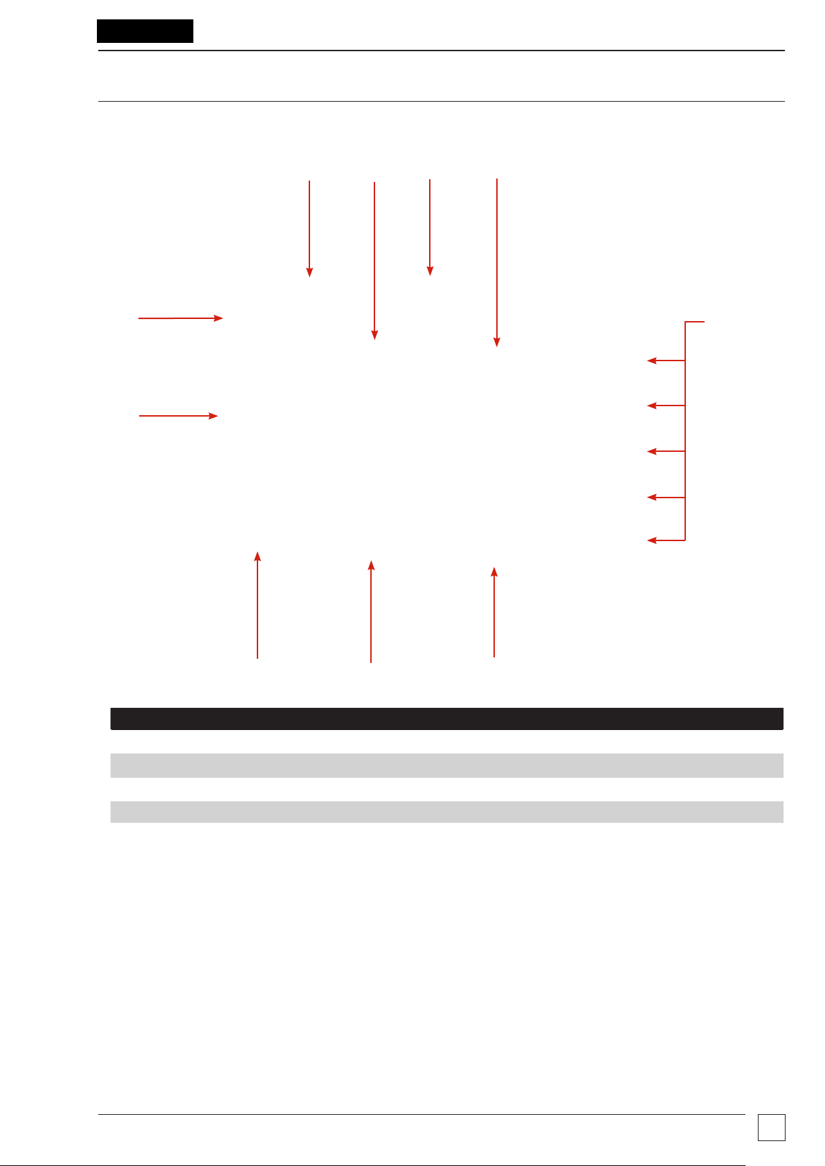
User interface
Overview
1
10
9
2
3
4
5
7
68
No. Description No. Description
1 External power / battery charge socket 6 Function switch (Controls (page 7))
2 Display 7 Navigation control panel (page 8)
3 USB: 1x Type A / 1x Type B 8 Mode switch (Controls (page 7))
4 Soft keys (page 9) 9 Save (Test Result Management (page 36))
5 Terminals (page 8) 10 External power LED (Power on / Charge (page 10))
www.megger.com
DET2/3
5
Page 12
Overview
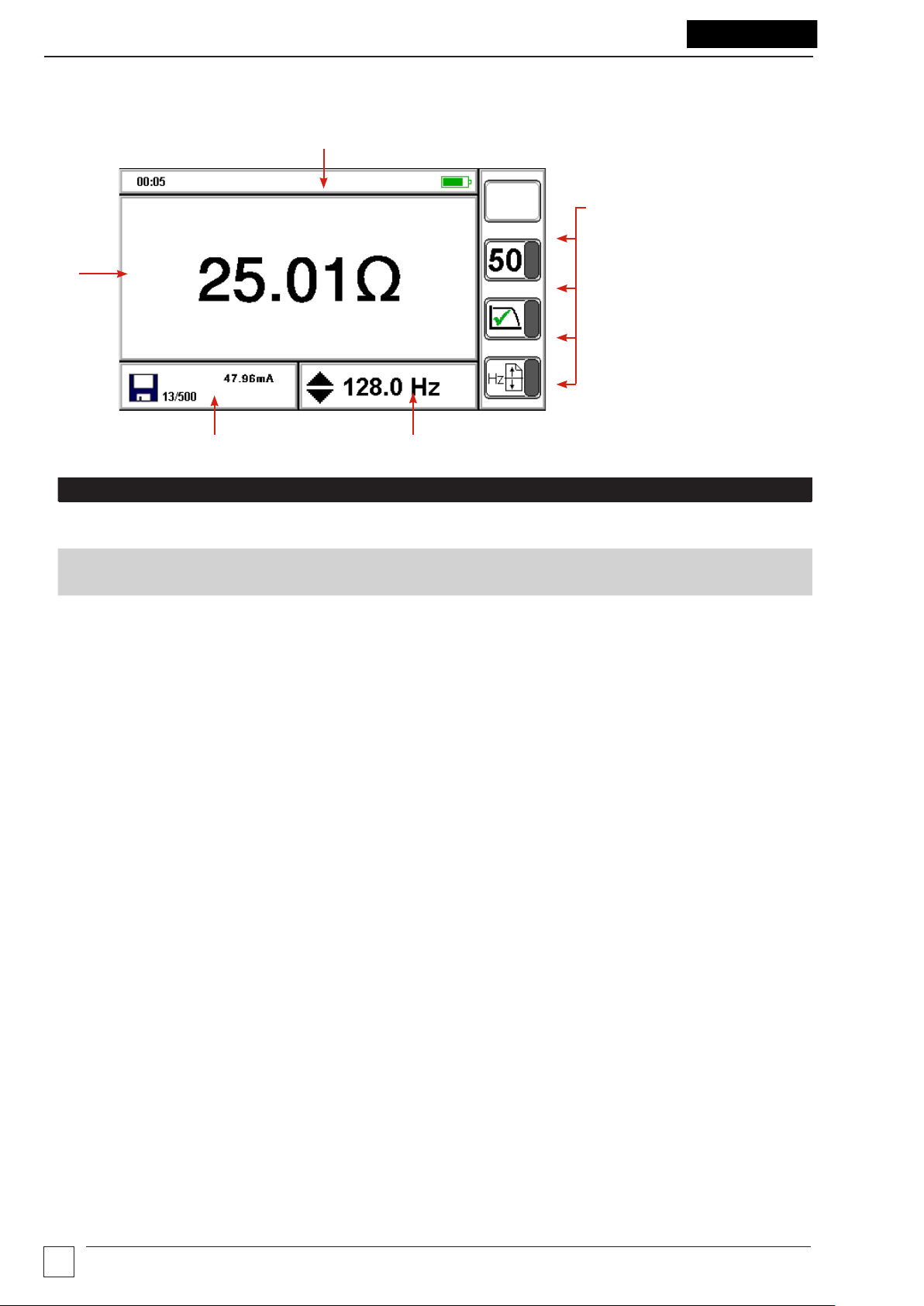
Display
2
1
3
4
4
5
No. Description No. Description
1 Status bar 4 Test mode: Secondary measurement result
Data management mode: Asset number
2 Main display / Primary measurement result 5 Test mode: Test parameters
Data management mode: Record name
3 Soft key functions
6
www.megger.comDET2/3
Page 13
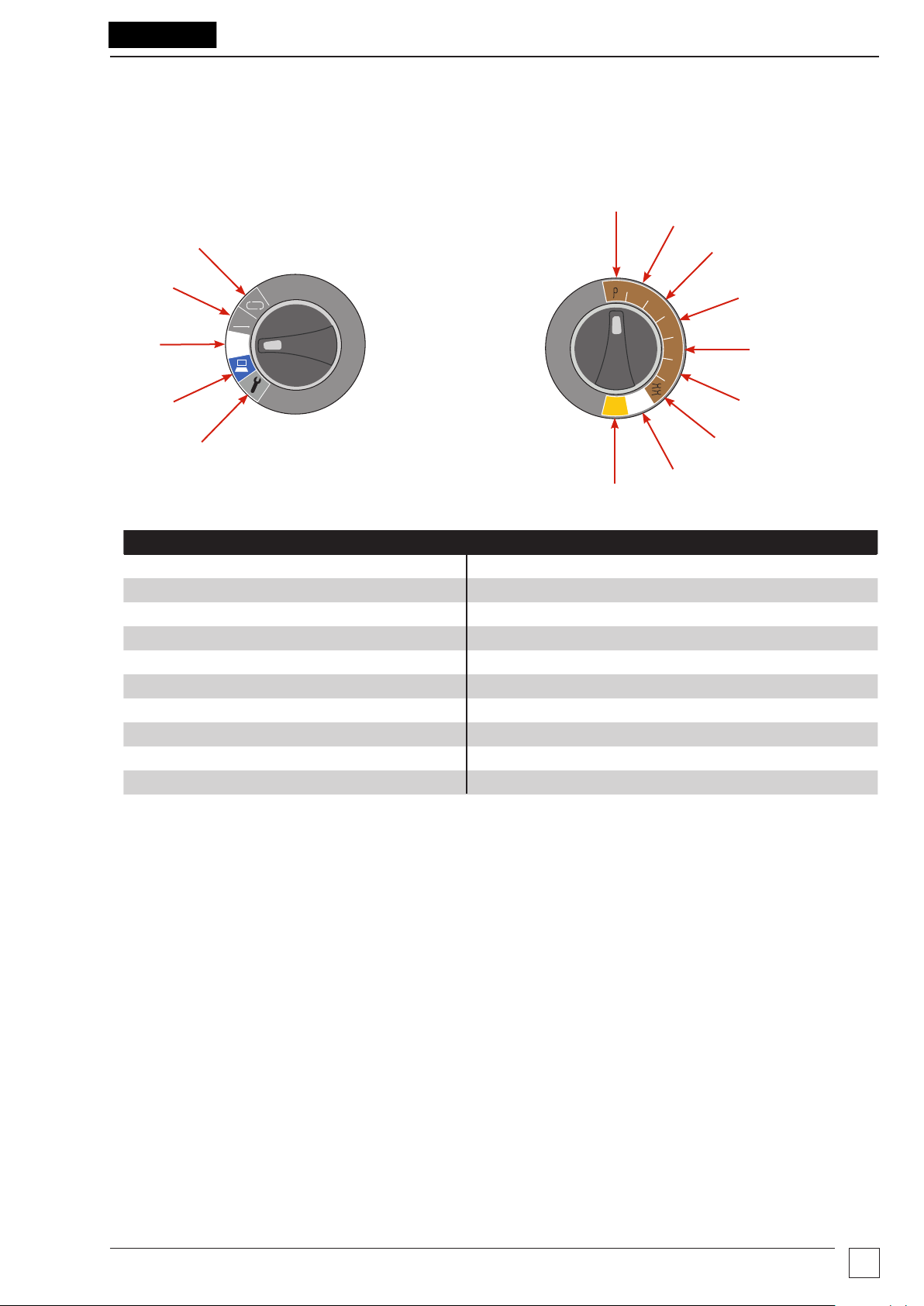
Controls
Refer to user interface (page 5).
Mode switch Function switch
1
Overview
1
2
3
2
MAN
3
4
OFF
5
No. Description No. Description
1 Continuous graphical mode (page 11) 1 ρ (Resistivity)
2 Manual mode (page 11) 2 4 Pole (ART)
3 Power on / off (page 10) 3 4 Pole
4 Test result management (page 33) 4 3 Pole (ART)
5 Set-up (page 12) 5 3 Pole
6 2 Pole
7 Dual clamp
8 A (leakage current)
9 Ω (continuity)
See Test methods and set-up (page 23).
4P
4P
3P
Ω
3P
2P
A
Ω
8
9
4
5
6
7
www.megger.com
DET2/3
7
Page 14
Overview
MVC1010
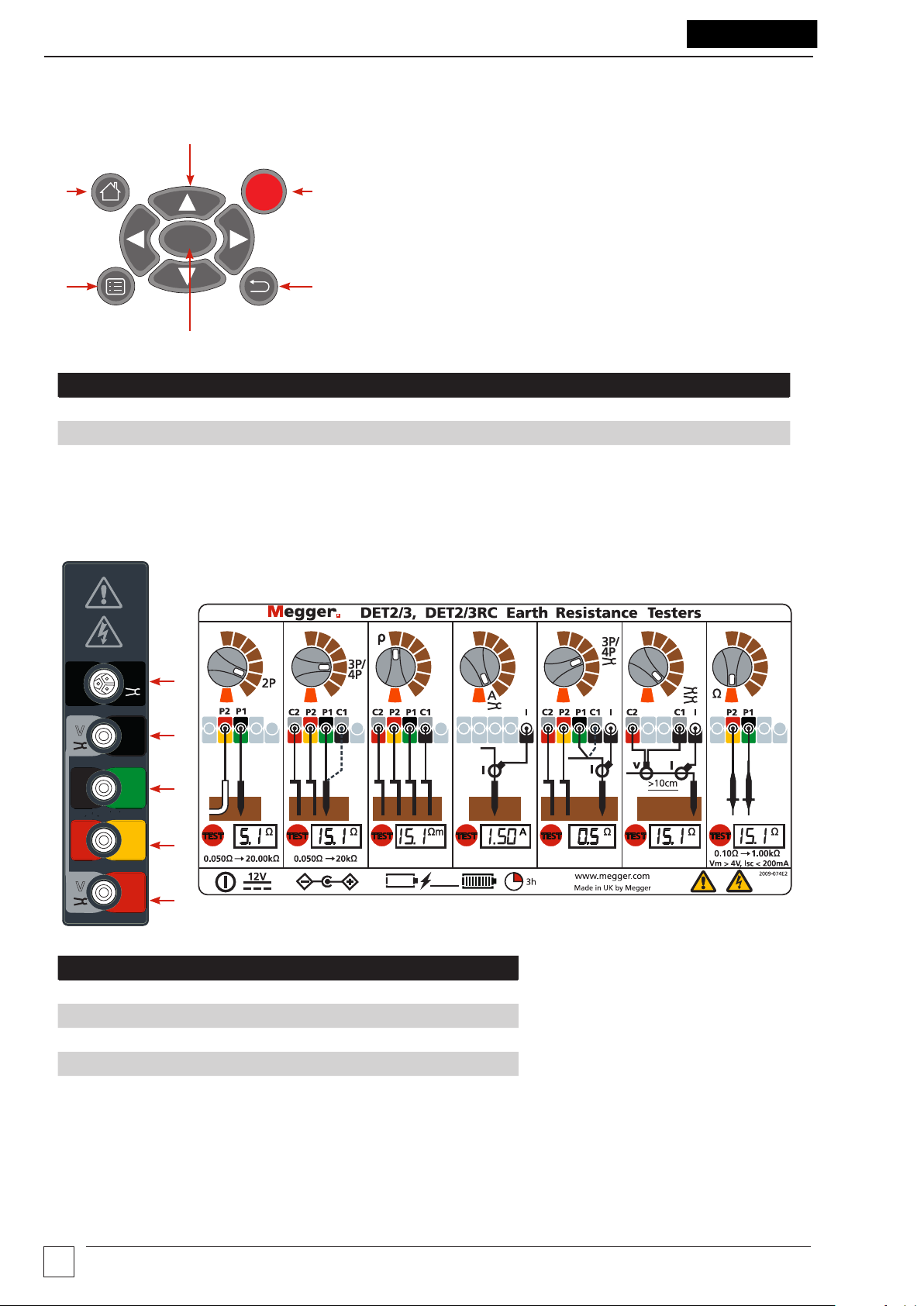
Navigation control panel
2
1
TEST
3
OK
6
5
No. Description No. Description
1 Home 4 Back
2 Navigation arrows 5 OK
3 Test 6 Menu
4
Terminals
See Test methods and set-up (page 23)
MCC1010
V
MVC1010
E
X
CAT IV 300V
Y
V
C1
P1
ES
P2
C2
H
I
I
E
S
1
2
3
4
5
No. Description
1 MCC1010 (used for ART, Noise current and stakeless tests)
2 MVC1010 / C1 E Voltage clamp, (current)
3 E/X / P1 ES (Potential)
4 Y / P2 S (Potential)
5 MVC1010 / C2 H Voltage clamp (current)
8
www.megger.comDET2/3
Page 15
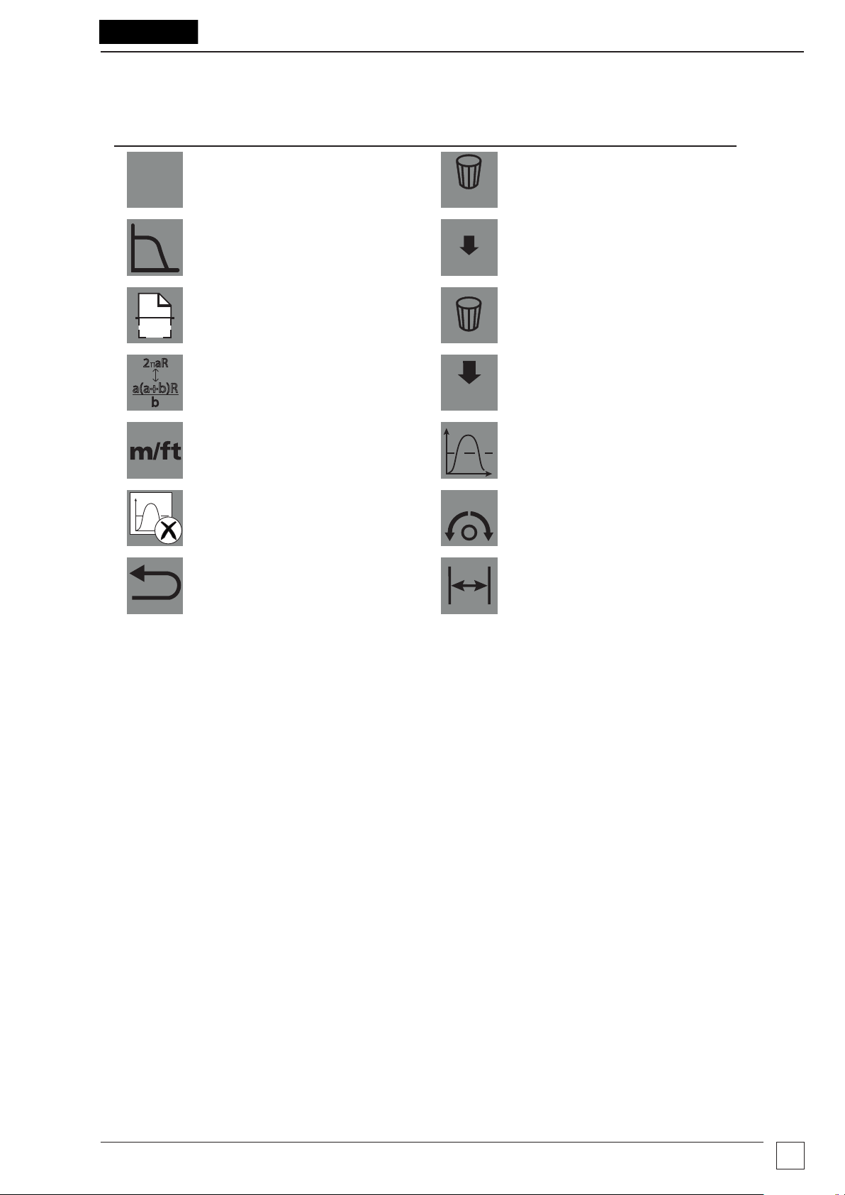
Soft keys
ALL
b
2 aR
Soft Key Description Soft Key Description
Overview
15/50V
Hz
a(a+b)R
Select 15 / 50 V
ALL
Noise filter on / off
Delete all test records
Send all test records to USB
USB
Automatic frequency Scan Delete single test record
Earth / ground resistivity test
method
Send single test record to USB
USB
Metres or feet Average
Clear
Back Resistivity spacing adjustment
NULL
Null
www.megger.com
DET2/3
9
Page 16
Operation
Operation
Before each use of the instrument, visually inspect the instrument case, test leads, stakes and connectors to
confirm their condition is good, with no damaged or broken insulation.
Power on / off
Rotate the mode switch away from Off to a mode to power up and activate the instrument
Rotate the mode switch to Off to power down the instrument.
Auto off
The instrument switches Off after a period of inactivity (user adjustable) (see General set-up (page 12)).
To start the instrument again rotate the mode switch to Off and then select a mode.
Power options
Internal battery
Mains supply: The instrument charges using the dc adapter, which will work at voltages between 100 and
240 V ac. You may continue to use the instrument while the internal battery is charging.
(See Battery charge (page 38)).
Green LED: On charge
Amber LED: External power On
12 V dc supply: Operate the instrument while connected to a 12 V dc supply. See 12 V supply (page 38).
See also Specifications (page 39).
Earth test options
Output voltage
The maximum output voltage of the instrument is ±50 V. This can be reduced to ±15 V for operation in situations
which require it. The most appropriate output voltage should be selected by the user based on local safety
procedures.
To change the output voltage
15/50V
Press
Test frequency
The instrument can either scan the usable frequency range to identify the test frequency with the lowest noise,
or the frequency set be manually set, as required.
Auto: Press
after the measurement mode is selected. The display will show the selected output voltage.
Hz
. The instrument searches for the best frequency
Manual: Press to set a frequency between 10 Hz and 200 Hz
Noise filter
Press (noise filter) to give additional noise rejection on the input signal in order to produce more stable
results, this will also extend the test duration.
10
www.megger.comDET2/3
Page 17
Operation
Test leads and terminal connections
Test lead set-up and terminal connections are described as part of the test procedure.
Important: When the instrument is connected to electrodes, make sure that all leads and cables are fully
unwound and laid out without loops.
Important: When running test leads out to each remote spike, take care not to lay them close to each other.
This is to minimise the effect of mutual inductance. Test leads must be spread out at least one metre apart.
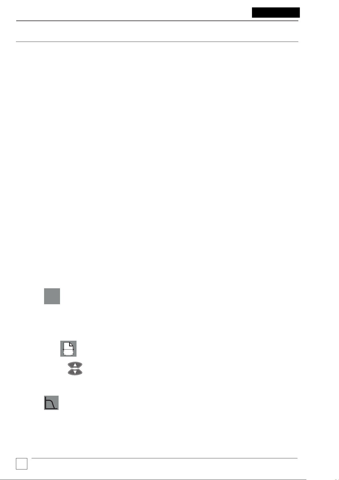
Test modes
The instrument can operate in two modes to do a test:
Manual mode
In manual mode the test result can be shown as a single digital read out result, or as a continuously updated
digital read out result.
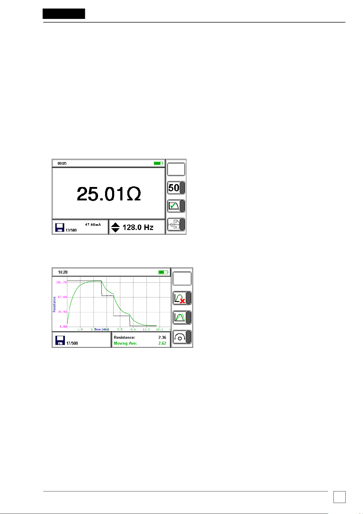
Continuous graphical mode
In continuous mode a continuous updated graph is displayed.
Green line: Measurement line
Black Line: Recorded average
www.megger.com
DET2/3
11
Page 18

Set-up
Set-up
This section details the instrument set-up.
Modify parameters
1. Set the Mode switch to .
2. Press
3. See instructions below for each set-up group.
Note: The set-up group screen is not active until
OK
to select a set-up group.
Setting in bold: Current setting
Setting underlined: Current selection
General set-up
1. Press to scroll through the parameters
OK
is pressed.
2. Press
3. Use to move left and right through the parameter options.
Date / Time
1. Press to modify current selected setting.
2. Press
Auto Off / Auto Dim / Brightness
1. Press to modify current selected setting.
2. Press
OK
OK
to select the highlighted parameter.
OK
to accept.
OK
to accept.
must be pressed to exit the parameter, even if no parameter was modified.
12
www.megger.comDET2/3
Page 19

Graph set-up
1. Press to scroll through the parameters.
Set-up
Graph length: 1, 5, 10, 15 min
Moving Average: 5, 10, 25, 50, 100
2. Press
3. Use to move through the options.
4. Press
OK
OK
to select the highlighted parameter.
OK
to accept.
must be pressed to exit the parameter, even if no parameter was modified.
Language set-up
Select the instrument language
1. Press to scroll through languages.
2. Press
www.megger.com
OK
to select the highlighted language.
DET2/3
13
Page 20

Earth / ground resistance
G
F
V
I
C1
E
E/X
CAT IV 300V
CAT IV 300V
CAT IV 300V
CAT IV 300V
Y
V
P1ESP2SC2
H
G
F
V
I
C1
E
E/X
CAT IV 300V
CAT IV 300V
CAT IV 300V
CAT IV 300V
Y
V
P1ESP2SC2
H
P1 P2 C2
Earth / ground resistance
Test procedure
Warning: Make sure the circuit is de-energised, before the instrument is connected for measurement.
Note: Manual or Continuous Graphical Mode (see Test modes (page 11).
Step Manual Mode Continuous Graphical Mode
OR
1
15 m to 25 m 15 m to 25 m
P1 P2 C2
15 m to 25 m 15 m to 25 m
Connect pins / stakes Connect pins / stakes
Note:
Set up test leads and stakes as required by each test (do not connect the test leads to the instrument):
Test Test Method Set-up
4P / 4P ART
3P / 3P ART
4P / 4P ART
3P / 3P ART
4P / 4P ART
3P / 3P ART
Fall of potential
Fall of potential
Fall of potential
Slope method
Slope method
61.8% rule
61.8% rule
Four terminal test lead set-up (page 23)
Three terminal test lead set-up (page 24)
Three terminal ART test lead set-up (page 24)
Slope four terminal test lead set-up (page 27)
Slope three terminal test lead set-up (page 28)
61.8% Four terminal test lead set-up (page 29)
61.8% Three terminal test lead set-up (page 29)
2P Two terminal earth resistance test (page 29)
2 Clamp Two clamp (stakeless) test (page 30)
4P
4P
3P
2
Ω
Ω
3P
2P
A
4P
4P
3P
Ω
3P
2P
A
Ω
Set the function Set the function
MAN
3
OFF
MAN
OFF
Set the mode Set the mode
14
www.megger.comDET2/3
Page 21

Earth / ground resistance
P2
P1
P2
C2
Manual mode Continuous graphical mode
CAT IV 300V
E/X
V
Y
CAT IV 300V
CAT IV 300V
P1
ES
P2
SC2H
C1
E
G
F
I
CAT IV 300V
V
OR
CAT IV 300V
CAT IV 300V
E/X
V
Y
CAT IV 300V
CAT IV 300V
P1
ES
P2
SC2H
C1
E
V
4
61.8% of EC 38.2% of EC
P1
C2
61.8% of EC 38.2% of EC
Connect test leads to instrument Connect test leads to instrument
5 Set test parameters Set test parameters
Note:
15/50V
15 or 50 test voltage
Manually select a frequency
Hz
Automatically select a frequency
Noise filter on or off
6 Start test Start test
Press
TEST
Press and hold
TEST
Press
TEST
7
until padlock icon appears
G
F
I
: Stop the current data stream and restart the graph.
: Activate / deactivate the average display
: Go back to test settings (the Ready screen)
8
End Test
9
Test ends
Press to stop
TEST
End Test
Press to stop
TEST
www.megger.com
DET2/3
15
Page 22

Earth / ground resistance
Manual mode Continuous graphical mode
10
11
Press / Repeat test
See Data management (page 33).
Repeat test if required. While the test result is shown, test parameters can be modified for the next test. If
required test parameters can be repeated.
OR
Press / Repeat test
16
www.megger.comDET2/3
Page 23

Earth / ground resistivity
C1
CAT IV 300V
P1
P2
C2
E
ES
S
H
I
V
E
X
Y
V
MVC1010 MVC1010
MCC1010
I
C1
CAT IV 300V
P1
P2
C2
E
ES
S
H
I
V
E
X
Y
V
MVC1010 MVC1010
MCC1010
I
a(a+b)R
b
2 aR
Earth / ground resistivity
Test procedure
Setup test
P1 (ES) C2 (H)P2 (S)
a a a
Wenner
1 Connect pins / stakes
P1 (ES) C2 (H)P2 (S)
a ab
Schlumberger
Note: Set up the test leads and stakes as required by the selected test method (on screen).
Do not connect the test leads to the instrument.
or
2 Set function to ρ
Set the mode
3
Manual or Continuous
(see Test modes (page 11).
4 Select test method
Set test measurements
4P
4P
A
Ω
MAN
OFF
Wenner or Schlumberger
Adjust parameters
Metres or Feet
3P
Ω
3P
2P
www.megger.com
DET2/3
17
Page 24

Earth / ground resistivity
Resistivity
The DET2/3 can measure and calculate resistivity using the Wenner or Schlumberger methods. These are very
similar, both involving placing four pins / stakes into the earth / ground. These only penetrate the soil by a short
distance.
MVC1010 MVC1010
Y
V
C2
P2
H
S
C1 (E) P1 (ES) C2 (H)P2 (S)
a a a
The Wenner method is the most common with the pins / stakes equally spaced in a line. The resistivity is
calculated in the equation:
ρ
X
E
CAT IV 300V
ES
P1
E
= 2πaR
V
MCC1010
C1
I
I
MVC1010 MVC1010
Y
V
C2
P2
H
S
C1 (E) P1 (ES) C2 (H)P2 (S)
a ab
CAT IV 300V
V
X
E
MCC1010
C1
ES
P1
E
I
I
The Schlumberger method has the potential pins / stakes closer together, with a<2b. The resistivity is calculated
in the equation:
ρ
=
5
Press
OK
a(a+b)
π
b
R
MVC1010 MVC1010
Y
V
C2
P2
H
S
CAT IV 300V
V
X
E
MCC1010
C1
ES
P1
E
I
I
6 Connect test leads to instrument
C1 (E) P1 (ES) C2 (H)P2 (S)
7 Set test parameters
18
15/50V
voltage
15 or 50 test
Set a frequency
Hz
Automatically
find a frequency
Noise Filter On
or Off
www.megger.comDET2/3
Page 25

8
Note:
Start test
Manual mode Continuous graphical mode
OR
Press and hold
TEST
Press
TEST
until padlock icon
appears
: Stop the current data stream and restart the graph.
: Activate / deactivate the average display
: Go back to test settings (the Ready screen)
Earth / ground resistivity
Press
TEST
9
End Test
10
Test ends
Press to stop
11
12
Press
/ Repeat test
Note: See Data management (page 33).
Repeat test if required. While the test result is shown, test parameters can be modified for the next
test, if required.
TEST
End Test
Press to stop
TEST
Press / Repeat test
www.megger.com
DET2/3
19
Page 26

Continuity Test
Continuity Test
Warning: Make sure the circuit is de-energised, before the instrument is connected for measurement.
Note: To remove any test lead resistance in the test result, Null the test leads (see Null test leads (page 21)).
Test procedure
1
Set function to Ω
2 Set the mode
3 Connect test leads to instrument
MAN
OFF
MVC1010 MVC1010
X
Y
V
CAT IV 300V
C2
ES
P2
H
S
4P
4P
3P
Ω
3P
2P
A
Ω
V
E
MCC1010
C1
P1
E
I
I
Start test
Manual mode Continuous graphical mode
4
Press to start
TEST
OR
Press
TEST
Clear: Stop the current data stream and restart the graph.
Average: Activate / deactivate the average display.
End test
5
Press to stop
TEST
Press
TEST
20
www.megger.comDET2/3
Page 27

Continuity Test
Manual mode Continuous graphical mode
6
Press
See Data management (page 33).
Note: Press Save at any time to save the current reading.
OR
Null test leads
Note: Test must be running to be able to Null the test leads.
The Null function only works when the measured resistance is less than 10 Ω.
Press
1. Put the two test lead tips firmly together.
2. Press .
When the test result shows, press again to activate / de-activate the Null process:
Null active: Result is minus the test lead resistance.
The Null function is active while results are continuously updated or when results update is stopped.
Null de-active: Result includes test lead resistance.
If the measured resistance is below zero, while Null is active, the result will show that it is too low to measure
(the instrument will not show negative resistance values).
www.megger.com
DET2/3
21
Page 28

Leakage Current Test
Leakage Current Test
Test procedure
1 Connect MCC1010
2 Set function to A
3 Set the mode
MAN
OFF
4P
4P
3P
Ω
3P
2P
A
Ω
4 Place MCC1010 around
conductor to be tested
Manual mode
5
Press to start
TEST
Note:
Clear: Stop the current data stream and restart the graph.
Average: Activate / deactivate the average display.
6
Press to stop
TEST
Start Test
OR
End Test
MVC1010 MVC1010
X
Y
V
E
CAT IV 300V
C2
ES
P2
H
P1
S
E
Continuous graphical mode
Press
TEST
Press
TEST
V
MCC1010
C1
I
I
7
8
See Data management (page 33).
22
Press
Press
www.megger.comDET2/3
Page 29

Test methods and set-up
P1 P2 C2
Test methods and set-up
The test methods detailed in this section is not exhaustive, see the booklet 'Getting Down To Earth' for more
information on other tests and methods.
Key to images in this section:
P: Potential spike
C: Current spike
E: Electrode
Fall of potential (FoP) test
Important: The current stake / pin, potential stake / pin and earth electrode must be placed in a straight line.
Important: When running test leads out to each remote stake / pin, take care not to lay them close to each
other. This is to minimise the effect of mutual inductance.
Four terminal test lead set-up
1. Insert the current stake / pin into the earth 30 to 50 metres away from the earth electrode to be tested.
2. Insert the potential stake / pin into the earth midway between the current test spike and the earth electrode.
3. Firmly connect terminal C1 and P1 to the earth electrode as shown.
4. Move the potential stake / pin three metres further away from the earth electrode and make a second
resistance measurement.
5. Move the potential stake / pin three metres nearer the electrode (than the original position) and make a third
resistance measurement.
If the three resistance readings are similar (within the required accuracy) then their average can be taken as the
resistance to earth of the electrode.
V
CAT IV 300V
CAT IV 300V
P2
S
C2
H
15 m to 25 m 15 m to 25 m
Y
CAT IV 300V
ES
P1
E/X
CAT IV 300V
E
V
C1
I
F
G
www.megger.com
DET2/3
23
Page 30

Test methods and set-up
100%
Four terminal ART test lead set-up
MVC1010 MVC1010
V
C2
H
Three terminal test lead set-up
V
CAT IV 300V
CAT IV 300V
C2
H
CAT IV 300V
ES
P2
S
P1
MCC1010
C1
E
I
I
V
X
Y
E
C1 (E)
P2 (S)
C2 (H)
P1 (ES)
62%
E/X
P1
CAT IV 300V
E
V
C1
I
F
G
Y
CAT IV 300V
ES
P2
S
15 m to 25 m 15 m to 25 m
P1 P2 C2
Important: The current stake / pin, potential spike and earth / ground electrode must be placed in a straight line.
Important: When running test leads out to each remote stake / pin, take care not to lay them close to each
other. This is to minimise the effect of mutual inductance.
Determine the earth electrode test lead resistance
The earth electrode test lead resistance can be determined separately.
1. Remove the test lead from the earth electrode and connect to the C2 and P2 terminals.
2. Press test.
The lead resistance can then be deducted from the earth resistance measurements.
This procedure is not required if the C1 and P1 terminals are connected by separate test leads.
Note: The result for a three terminal test will include the resistance of the test lead used to connect to the earth
electrode under test. The resistance can be measured by connecting the lead to the P1(X) and P2(Y) terminals,
selecting a 2P test and pressing the test button. This lead resistance can be subtracted from the earth resistance
measurements.
24
www.megger.comDET2/3
Page 31

Three terminal ART test lead set-up
Test methods and set-up
C2 (H)
MVC1010 MVC1010
Y
V
C2
H
CAT IV 300V
P2
S
P2 (S)
X
E
ES
P1
100%
V
MCC1010
C1
E
I
I
P1 (ES)
62%
Slope method (FoP)
Description
Extract from the technical guide Getting Down to Earth:
It has been shown that the true earth resistance of an electrode system is obtained when the temporary potential
P is positioned at a distance from the electrical centre of the system equal to 61.8% of the distance from the
electrical centre to the temporary current probe. This principle is used in the technique called 'Intersecting Curves'
explained in Getting Down to Earth. It becomes apparent that the method is complex in nature and requires
some trial and error calculations.
A further technique was evolved and is described below. It is easier to use and has been shown to give
satisfactory results, both in theoretical and practical cases and when the soil is nonhomogenous. It is called the
Slope Method.
To apply the Slope Method:
1. Choose a convenient rod E to which the Earth Tester can be connected. E is one of many parallel rods
forming the complex earth system.
2. Insert the current probe at a distance (DC) from E (DC is normally two to three times the maximum dimension
of the system).
3. Insert potential probes at distances equal to 20% of DC, 40% of DC and 60% DC.
See examples in step 4.
4. Measure the earth resistance using each potential probe in turn. Let these resistance values be R1, R2 and R3
respectively.
Examples:
R1 = 0.2 x DC
R2 = 0.4 x DC
R3 = 0.6 x D
C
5. Calculate the value of:
R3 - R
µ =
R2 - R
2
1
The resultant is called μ and represents the change of slope of the resistance / distance curve.
6. Refer to Table 1: Values of DP / DC for various values of µ (page 27) to find the corresponding value of
DP/DC for μ.
www.megger.com
DET2/3
25
Page 32

Test methods and set-up
7. Since DC (distance to the current probe) is already known, calculate a new DP (distance of the potential probe)
then insert the potential probe at this new distance from E.
DP= DP/DC x D
C
Now measure the earth resistance by placing the potential probe at this new distance DP. This measurement is
known as the 'true' resistance.
8. Repeat the whole process for a larger value of DC. If the 'true' resistance decreases appreciably as DC is
increased, it is necessary to increase the distance of DC still further. After making a number of tests and
plotting the 'true' resistance, the curve will begin to show less of a decrease and will indicate more stable
readings. It is at this point the resistance of the earthing system is noted.
Note: As with other earth testing techniques, some experimentation may be necessary to ascertain if the practical
result is as accurate as the theory appears to indicate.
The Slope Method has been designed to eliminate the need for impractically long leads by the ability to
interpolate the correct distance along the combined resistance curve, i.e. the curve of the current probe’s
resistance superimposed upon that of the tested grid, without sufficient spacing to produce the characteristic 'flat
portion' between.
One particular observation on the Slope Method is that if the calculation of μ is greater than that given in the
table, the distance C must be increased.
Secondly, before the measured values for R
, R2 and R3 can be accepted with a degree of confidence, it is
1
recommended that a curve be plotted which will identify any localized effects and eliminate uncharacteristic
readings from the calculations. Thirdly, it is also suggested that the test be repeated in different directions and
with different spacings. The various results should exhibit a reasonable degree of agreement.
26
www.megger.comDET2/3
Page 33

Table 1: Values of DP / DC for various values of µ
Test methods and set-up
µ DP / D
C
µ DP / D
C
µ DP / D
0.40 0.643 0.80 0.580 1.20 0.494
0.41 0.642 0.81 0.579 1.21 0.491
0.42 0.640 0.82 0.577 1.22 0.488
0.43 0.639 0.83 0.575 1.23 0.486
0.44 0.637 0.84 0.573 1.24 0.483
0.45 0.636 0.85 0.571 1.25 0.480
0.46 0.635 0.86 0.569 1.26 0.477
0.47 0.633 0.87 0.567 1.27 0.474
0.48 0.632 0.88 0.566 1.28 0.471
0.49 0.630 0.89 0.564 1.29 0.468
0.50 0.629 0.90 0.562 1.30 0.465
0.51 0.627 0.91 0.560 1.31 0.462
0.52 0.626 0.92 0.558 1.32 0.458
0.53 0.624 0.93 0.556 1.33 0.455
0.54 0.623 0.94 0.554 1.34 0.452
0.55 0.621 0.95 0.552 1.35 0.448
0.56 0.620 0.96 0.550 1.36 0.445
0.57 0.618 0.97 0.548 1.37 0.441
0.58 0.617 0.98 0.546 1.38 0.438
0.59 0.615 0.99 0.544 1.39 0.434
C
0.60 0.614 1.00 0.542 1.40 0.431
0.61 0.612 1.01 0.539 1.41 0.427
0.62 0.610 1.02 0.537 1.42 0.423
0.63 0.609 1.03 0.535 1.43 0.418
0.64 0.607 1.04 0.533 1.44 0.414
0.65 0.606 1.05 0.531 1.45 0.410
0.66 0.604 1.06 0.528 1.46 0.406
0.67 0.602 1.07 0.526 1.47 0.401
0.68 0.601 1.08 0.524 1.48 0.397
0.69 0.599 1.09 0.522 1.49 0.393
0.70 0.597 1.10 0.519 1.50 0.389
0.71 0.596 1.11 0.517 1.51 0.384
0.72 0.594 1.12 0.514 1.52 0.379
0.73 0.592 1.13 0.512 1.53 0.374
0.74 0.591 1.14 0.509 1.54 0.369
0.75 0.589 1.15 0.507 1.55 0.364
0.76 0.587 1.16 0.504 1.56 0.358
0.77 0.585 1.17 0.502 1.57 0.352
0.78 0.584 1.18 0.499 1.58 0.347
0.79 0.582 1.19 0.497 1.59 0.341
www.megger.com
DET2/3
27
Page 34

Test methods and set-up
Slope four terminal test lead set-up
V
CAT IV 300V
C2
H
P1 P2 C2
CAT IV 300V
a
Y
P2
S
Slope three terminal test lead set-up
V
CAT IV 300V
CAT IV 300V
P2
S
C2
H
CAT IV 300V
Y
ES
CAT IV 300V
ES
E/X
P1
> 50 m
E/X
P1
CAT IV 300V
E
CAT IV 300V
V
C1
I
aa
V
E
C1
aaa
I
F
F
G
aa
G
> 50 m
aa
aaa
P2
a
P1
aa
C2
28
www.megger.comDET2/3
Page 35

61.8% Rule (FoP)
P1
61.8% Four terminal test lead set-up
Test methods and set-up
V
CAT IV 300V
C2
H
61.8% of EC 38.2% of EC
P1
CAT IV 300V
S
P2
Y
CAT IV 300V
ES
61.8% Three terminal test lead set-up
CAT IV 300V
H
V
C2
CAT IV 300V
S
Y
P2
E/X
P1
CAT IV 300V
ES
CAT IV 300V
E
P1
E/X
V
C1
CAT IV 300V
G
F
I
P2
V
C1
E
F
I
C2
G
www.megger.com
100%
P2 C2
DET2/3
29
Page 36

Test methods and set-up
Two terminal earth resistance test
Warning: Make sure the circuit is de-energised, before the instrument is connected for measurement.
This will measure the resistance between the P1(X) and P2(Y) terminals using an ac test voltage. This method may
not be suitable for continuity and bonding tests (refer to local regulations).
Note: The test voltage used for the two pole resistance test is ac and may not be suitable for all continuity tests
(see local regulations).
Note: If the earth noise voltage is above 50 V peak to peak (18 Vrms), the display will show a warning triangle
and an excessive noise voltage indicator.
Set up the test leads and stakes as required (do not connect the test leads to the instrument):
P1 (E)
MVC1010 MVC1010
Y
V
C2
H
CAT IV 300V
P2
S
V
X
E
ES
P1
MCC1010
C1
E
I
I
P2 (H)
Two clamp (stakeless) test
The two clamp (stakeless) test uses both the MVC1010 and MCC1010 to obtain a measurement for the electrode
under test.
MVC1010 MVC1010
Y
V
C2
H
CAT IV 300V
P2
S
V
X
E
ES
P1
MCC1010
C1
E
I
I
30
www.megger.comDET2/3
Page 37

Calibration check tools
Calibration check tools
The instrument's calibration should be checked, before and after each test, against the calibration check tool.
Instrument calibration check
1. Make sure that the mode switch is set to Off.
2. Connect the instrument as shown:
MVC1010 MVC1010
Y
V
C2
H
CAT IV 300V
P2
S
V
X
E
ES
P1
MCC1010
C1
E
I
I
Calibration
adaptor
3. Set the function switch to 2P, 3P or 4P.
4. Start a test:
Press and release TEST.
The instrument completes pre-measurement checks.
The resistance is shown and should match the value written on the calibration check tool.
Checking instrument accuracy
Instrument accuracy: 0.5% (+ 2 digits). At 25 Ω is this gives an allowed measurement range of +/- 0.145 Ω.
Calibration check tool accuracy: 0.1%. At 25 Ω this gives an allowed variation of 0.025 Ω.
Therefore a test, which uses the 4 pole position, will produce the following bands:
25 + 0.145 + 0.025 = 25.17 (a figure greater than this is out of specification)
25 + 0.145 – 0.025 = 25.12 (a figure between 25.12 and 25.17 is possibly out of specification)
25 – 0.145 + 0.025 = 24.88 (a figure between 24.88 and 25.12 is in specification)
25 – 0.145 – 0.025 = 24.83 (a figure less than this is out of specification)
www.megger.com
DET2/3
31
Page 38

Calibration check tools
Clamp calibration check
1. Make sure that the mode switch is set to Off.
2. Connect the instrument as shown:
MVC1010 MVC1010
Y
V
H
CAT IV 300V
C2
P2
S
V
X
E
ES
P1
Dual Clamp calibration
check
Hold clamps against
these faces
MCC1010
C1
E
I
I
3. Close the MCC1010 around one loop of the clamp calibration check tool.
4. Close the MVC1010 around the other loop of the clamp calibration check tool.
5. Make sure that there is a minimum separation of 100 mm between the MCC1010 and MVC1010.
6. Set the function switch to
.
7. Start a test:
Press and release TEST.
The instrument completes pre-measurement checks.
The two-clamp resistance is shown and should match the value written on the clamp calibration check tool.
Note: Make sure that the MCC1010 and MVC1010 jaw mating surfaces are free of dust and contamination and
that they make a good contact with each other when the jaws are closed.
32
www.megger.comDET2/3
Page 39

Data management
Data management
Use test result management mode of view saved test results and transfer saved test results to USB drive or PC.
Test result data is saved in two formats:
As a Data File: Data saved from manual or guided mode saved as a single data file.
As a Graph File: Data saved from continuous mode saved as a graph of a complete test.
Data file records Graph file records
Up to 500 test records can be saved (data and graph files). A test record is either:
Manual mode: A single test record, several saved records may be required to complete a test.
Continuous mode: A single test record as a graph file.
Note: A pop-up error dialogue box will show when the memory is full to tell the user to clear some space.
Save test result
1. Press when the save icon is displayed.
The test is assigned a record number.
To edit a record file name as...
1. Set the mode switch to
2. Press
3. Press
4. Press
(Red bar visible)
5. Press to select a test result
www.megger.com
to select or
OK
OK
to select record name
DET2/3
33
Page 40

Data management
6. Press
(Red bar visible)
7. Press
8. Enter a test result three digit number.
Keyboard show - use arrow keys to navigate.
9. Press to save and return.
OK
Data file: Test001.tab.
Graph file: Graph001.tab.
to move to Asset ID.
OK
.
The save icon will display when save function is available.
Press save button and a record number will display.
Note: In continuous graphical mode save can be pressed at any time.
USB connection
A USB type socket is provided for this purpose on the top of the DET2/3. The position is clearly marked with a
USB symbol.
34
www.megger.comDET2/3
Page 41

Single test result: download or delete
ALL
Connect a USB memory device to the instrument.
1. Set the mode switch to
2. Select or
Data management
3. Press
4. Press
OK
OK
to select record number
(Red bar visible)
5. Press
to select a test result:
Download a single test record Delete a single test record
Press
The selected test record is downloaded (copied)
USB
Press
The selected test record is deleted
to the connected device
Multiple test results: download or delete
6. Select or .
7. Press
OK
.
Download all test records Delete all test records
Press
The selected test records are downloaded
USB
.
Press
All saved test records are deleted
(copied) to the connected device
www.megger.com
DET2/3
35
Page 42

Maintenance
Maintenance
General maintenance
Test leads should be checked before use for damage and continuity.
Ensure the unit is kept clean and dry after use.
Close all covers and flaps when not in use.
Cleaning
1. If connected, disconnect from mains power.
2. Wipe the Instrument with a clean cloth dampened with either water or isopropyl alcohol (IPA).
Battery
Caution: Old batteries must be disposed of in accordance with local regulations.
Caution: Always set the instrument to Off and remove test leads before battery is removed and
installed. Only use approved batteries supplied by Megger.
Approved batteries (see Specifications (page 39)).
To help maintain the health, reliability and longevity of the installed battery:
Make sure that the battery is fully charged before the instrument is used
Keep the battery charged up whenever possible while in use. Li-Ion batteries prefer frequent top-ups and
should never be left in a flat state for extended periods as this can cause permanent damage
If the battery is to be stored for extended periods maintain a charge of 40%, allow for some discharge and
maintenance of the protection circuit.
Store the battery in a cool, dry place. Li-ion batteries can get stressed when exposed to heat which can
reduce its life. See Specifications (page 39).
Battery status
Battery charging
Battery charged Battery low, 0%-5%, flashing
Battery down to 6%-26%
Battery discharging Battery faulty/error, flashing
When running from the battery, the above will indicate the current state of charge (the icon will be filled
proportionally to the state of charge). When the battery is charging, it will show an animation that starts with the
current state of charge and fills the indicator to 100 %, then repeats. Once the battery is full, the animation will
stop. If the charger is connected (and on), but unable to charge the battery, the icon will flash.
Capacity and typical charge life 10 hours max.
36
www.megger.comDET2/3
Page 43

Battery replacement.
Maintenance
1
2
3
7
4
5
6
Warning: Disconnect all leads before removing case.
Caution: Protect the face and switches of the instrument when turning it upside-down.
Note: Replace with Megger approved battery, part number 1002-552 only.
1. Remove lid by opening to approximately 70° and sliding right.
2. Switch the instrument Off.
3. Disconnect all leads .
4. Invert the lower case and rest the front panel on a soft surface so as not to damage the keypad.
5. Remove 4 fixing screws (1) and lift off the case.
6. Undo 4 fixing screws (2), remove battery cover (3).
7. Disconnect battery connector (4) and lift foam strips (7) to release the battery lead.
8. Remove battery (5).
9. Connect new battery to connector (5).
10. Install new battery ensuring correct orientation and that lead is correctly routed in slot (6). Secure lead using
foam strips (7).
Warning: Do not reconnect any test leads until the battery cover is fitted.
1. Refit battery cover (3) and secure using 4 screws (2) to torque 20 cNm.
2. Refit case and secure using 4 screws (1) to torque 40 cNm.
3. Turn instrument upright and refit lid.
Note: The battery must be disposed of according to local environmental regulations.
www.megger.com
DET2/3
37
Page 44

Maintenance
Battery charge
Note: Make sure the ambient temperature is correct to charge a battery (see Specifications (page 39)).
When the battery status indicator shows the battery is nearly discharged or is discharged, recharge the battery as
detailed below.
The DET2/3 can be used while the battery is on charge. The instrument will charge faster when switched off.
A charge cycle on a fully discharged battery takes approximately four hours (see the Battery status (page 36)).
1. Switch the instrument Off.
2. Disconnect the instrument from all electrical circuits.
3. Open the external power socket rubber door.
4. Connect the ac / dc adaptor (amber LED shows for two seconds then changes to green (charging)).
5. When fully charged the LED shows steady amber (power connected - battery charged).
6. Once the charge cycle has started the instrument can be used as normal.
12 V supply
When the battery status indicator shows the battery is nearly discharged or is discharged, use the power supply
provided with the instrument to recharge the battery. The instrument will function normally with the power
supply in use. Use only the power supply provided by Megger; other supplies may introduce noise into the
measurement, affecting accuracy and instrument stability.
Note: The LED indicating the instrument is connected to an external 12 V supply will go amber if the charger is
connected (and on), but unable to charge.
The instrument will now operate on the 12 V dc supply.
38
www.megger.comDET2/3
Page 45

Specifications
Specifications
Only values with tolerance or limits are guaranteed data. Parameters without tolerances are for information only.
Measurement specifications
2, 3 and 4 terminal resistance
Range 0.001 Ω to 20.00 kΩ Auto range
Accuracy
3P
2P
Operational uncertainty ±2% of reading ±2 digits
4 and 3 terminal ART (selective) resistance
Range 0.01 Ω to 10.00 kΩ auto range
Accuracy ±5% accuracy (±3 digits) at 23°C ±2°C
Stakeless resistance
Range 0.01 Ω to 200 Ω
Accuracy ±7% (±3 digits)
Test to standards BS 7430 (Earthing)
Test frequency 2P, 3P & 4P
resistivity
Test frequency dual clamp,
3p ART & 4P ART
Test current 50 mA max.
Maximum output voltage 50 V rms
Maximum interference 50 V peak to peak
Continuity
Range 0.01 Ω to 1 kΩ (3 digits)
Accuracy ±3% (±2 digits)
Test Current Up to 205 mA
Lead Null < 10 Ω
Leakage current
Range 0.00 A to 2.00 A at 5% (+3 digits)
Accuracy ±5% (±3 digits)
at 23 °C ±0.5% of reading ±2 digits
±10 mΩ
±20 mΩ
Meets IEC61557 operational uncertainty requirement with readings over 10 mΩ
when spike resistances are below 100 Ω
±5% of reading ±2 digits ±10 mΩ
Meets IEC61557 operational uncertainty requirement with readings over 50 mΩ
BS 62305 (Lightning)
IEEE Standard 81
10 Hz to 200 Hz (steps of 0.5 Hz)
70 Hz to 200 Hz (steps of 0.5 Hz)
www.megger.com
DET2/3
39
Page 46

Specifications
Instrument specifications
Display Backlit, colour, WQVGA display 5.25 in
Operating temperature From -10 to 40 °C (14 to 104 °F)
Operating humidity 90% RH max at 40 °C
Storage temperature From -20 to 60 °C (4 to 140 °F)
Temperature coefficient < ±0.1% per °C over operating Temp.
Environmental protection IP54 operational (lid open)
IP65 storage (lid closed)
Altitude: Up to 2000 m above sea-level.
Measurement connection rating CAT IV 300 V (clamp terminals not isolated from measurement terminals)
Measurement output rating ±50 V 1 A, ac or dc.
Power supply Internal Li-ion battery (rechargeable / replaceable)
External 100 to 240 V ac, 50 - 60 Hz (with adaptor)
External 18V dc supply (65 W)
Battery life 10 h. max. (typically)
Battery charge time Fast recharge to 50%, 3 h for 100%.
Ambient temperature
(battery charge)
Safety Meets IEC 61010
EMC Meets IEC 61326
Dimensions 315 x 285 x 181 mm
Weight 4.8 kg (10.6 lb)
PC data download USB 2.0
Data Management Internal 500 record storage
USB Host Send data to pen drive
Resistivity calculation Wenner
Tests 2P, 3P, ART (Selective), 4P, Stakeless (clamp) modes
Real time clock Yes
RoHS compliant Yes
0 - 40 ºC
(13.8 x 11.2 x 7.1 in)
Schlumberger
Instrument calibration check tool
Electrical specification
Resistance 25 Ω ±0.1%
Mechanical specification
Dimensions 60 x 55 x 25 mm (2.5 x 2.25 x 1 in)
Weight 0.1 kg (0.2 lb) approximately
40
www.megger.comDET2/3
Page 47

Clamp calibration check tool
Electrical specification
Resistance 25 Ω ±0.1%
Mechanical specification
Operating temperature -10 °C to 50 °C (14 °F to 122 °F)
0% to 85% RH at +35 °C (95 °F)
Storage temperature -20 °C to 70 °C (-4 °F to 158 °F)
Dimensions 111 x 216 x 45 mm (4.4 x 8.5 x 1.8 in)
Weight 0.1 kg (0.2 lb) approximately
Specifications
www.megger.com
DET2/3
41
Page 48

Accessories
Accessories
Warning: Use only Megger approved test leads and accessories with this instrument.
Item Part Number
Cable reel kit ETK30 1010-176
Cable reel kit ETK50 1010-177
Cable reel kit ETK100 1010-178
Cable reel kit ETK50C 1010-179
Cable reel kit ETK100C 1010-180
Clamp MCC1010 1010-516
Clamp MVC1010 1010-518
12 V dc power lead 1004-183
Terminal adapter, detachable retro-fit for C1, P1, P2, C2 connectors 6220-803
Power supply 18 V >3.5 A 1010-793
42
www.megger.comDET2/3
Page 49

Repair and warranty
Repair and warranty
If an instrument’s protection has been impaired it should not be used, but sent for repair by suitably trained
and qualified personnel. The protection is likely to be impaired if for example, it shows visible damage, fails to
perform the intended measurements, has been subjected to prolonged storage under unfavourable conditions, or
has been subjected to severe transport stresses.
New instruments are guaranteed for one year from the date of purchase by the user.
Note: Any unauthorized prior repair or adjustment will automatically invalidate the warranty and calibration.
Note: No user repair is possible beyond that which is described within this manual, i.e. battery replacement and
cleaning. Any attempt to disassemble or repair beyond this point will invalidate any warranty on the item.
www.megger.com
DET2/3
43
Page 50

Calibration and repair
Calibration and repair
Megger operate fully traceable calibration and repair facilities to make sure your instrument continues to provide
the high standard of performance and workmanship that is expected. These facilities are complemented by a
worldwide network of approved repair and calibration companies, which offer excellent in-service care for your
Megger products.
For service requirements for Megger Instruments contact:
Megger Limited
Archcliffe Road
Dover
Kent
CT17 9EN
England
Tel: +44 (0) 1304 502 243
Fax: +44 (0) 1304 207 342
or Megger
Valley Forge Corporate Centre
2621 Van Buren Avenue
Norristown
PA 19403
U.S.A.
Tel: +1 610 676 8579
Fax: +1 610 676 8625
Return procedure
Warning: This instrument contains a lithium ion high energy battery pack.
UK and USA Service Centres
1. When an instrument requires recalibration, or in the event of a repair being necessary, a Returns Authorisation
(RA) number must first be obtained from one of the addresses shown above.
The following information is to be provided to enable the Service Department to prepare in advance for
receipt of your instrument and to provide the best possible service to you:
Model (for example, DET2/3)
Serial number (found on the underside of the case or on the calibration certificate)
Reason for return (for example, calibration required, or repair)
Details of the fault if the instrument is to be repaired
2. Make a note of the RA number. A returns label can be emailed or faxed to you if required.
3. Pack the instrument carefully to prevent damage in transit.
4. Before the instrument is sent to Megger, freight paid, make sure that the returns label is attached, or that the
RA number is clearly marked on the outside of the package and on any correspondence.
Copies of the original purchase invoice and packing note should be sent simultaneously by airmail to expedite
clearance through customs. In the case of instruments which require repair outside the warranty period, an
immediate quotation can be provided when obtaining the RA number.
5. Track the progress on line at www.megger.com.
44
www.megger.comDET2/3
Page 51

Calibration and repair
Approved service centres
A list of Approved Service Centres can be obtained from the UK address above, or from Megger’s website at
www.megger.com
www.megger.com
DET2/3
45
Page 52

End of life
End of life
WEEE directive
The crossed out wheeled bin symbol placed on Megger products is a reminder not to dispose of the product at
the end of its life with general waste.
Megger is registered in the UK as a Producer of Electrical and Electronic Equipment (registration No.: WEE/
HE0146QT).
For further information about disposal of the product consult your local Megger company or distributor or visit
your local Megger website.
Battery disposal
The crossed out wheeled bin symbol placed on a battery is a reminder not to dispose of batteries with general
waste at the end of their life.
This instrument contains a rechargeable Li-ion battery, which is located under the battery cover at the bottom of
the instrument. To remove the Li-ion battery follow the instructions in Battery (page 36).
A spent Li-ion battery is classified as an Industrial Battery. For disposal in the UK contact Megger Ltd.
For disposal of batteries in other parts of the EU contact your local Megger branch or distributor.
Megger is registered in the UK as a producer of batteries (registration No.: BPRN00142).
For Further information see www.megger.com
46
www.megger.comDET2/3
Page 53

Declaration of conformity
Declaration of conformity
Hereby, Megger Instruments Limited declares that radio equipment manufactured by Megger Instruments
Limited described in this user guide is in compliance with Directive 2014/53/EU. Other equipment manufactured
by Megger Instruments Limited described in this user guide is in compliance with Directives 2014/30/EU and
2014/35/EU where they apply.
The full text of Megger Instruments EU declarations of conformity are available at the following internet address:
megger.com/eu-dofc
www.megger.com
DET2/3
47
Page 54

Bibliography
Bibliography
Getting Down to Earth, published by and available from Megger, Pt. No.: 21500-072.
48
www.megger.comDET2/3
Page 55

Notes
Notes
www.megger.com
DET2/3
49
Page 56

Megger Limited
Archcliffe Road
Dover
Kent
CT17 9EN
ENGLAND
T +44 (0)1 304 502101
F +44 (0)1 304 207342
Megger GmbH
Obere Zeil 2 61440
Oberursel,
Germany
T. 06171-92987-0
F. 06171-92987-19
Megger USA - Valley Forge
Valley Forge Corporate Center
2621 Van Buren Avenue
Norristown
Pennsylvania,
19403 USA
T. 1-610 676 8500
F. 1-610-676-8610
Megger USA - Dallas
4271 Bronze Way
Dallas TX 75237-1019 USA
T 800 723 2861 (USA only)
T +1 214 333 3201
F +1 214 331 7399
USsales@megger.com
Megger AB
Rinkebyvägen 19, Box 724,
SE-182 17 Danderyd
T. 08 510 195 00
E. seinfo@megger.com
OTHER TECHNICAL SALES OFFICES
Toronto CANADA, Sydney AUSTRALIA, Madrid SPAIN and Mumbai INDIA.
Megger products are distributed in 146 countries worldwide.
This instrument is manufactured in the United Kingdom.
The company reserves the right to change the specification or design without prior notice.
Megger is a registered trademark
The Bluetooth ® word mark and logos are registered trademarks owned by Bluetooth SIG, Inc and is used
under licence.
DET23_UG_en_V02 27 March 2018 10:02 AM
www.megger.com
 Loading...