

Page 1

DET2/2
Digital Earth Tester
USER GUIDE
GUIDE DE L’UTILISATEUR
GEBRAUCHSANLEITUNG
GUÍA DEL USUARIO
M
Page 2

SAFETY WARNINGS
• Special precautions are necessary when ‘live’ earths may be encountered, and isolation switches and fuses
are needed in this situation. See ‘Operation - Earth Testing Safety Precautions’.
• The earth spikes, test leads and their terminations must not be touched while the instrument is switched ‘On’.
• When working near high tension systems, rubber gloves and shoes should be worn.
• The DET2/2 must be disconnected from any external circuit while its battery cells are being charged.
• A 12 V d.c. battery must not be used as an external supply while it is still connected to the vehicle.
• Replacement fuses must be of the correct type and rating
• Before charging the DET2/2 battery ensure that the correct supply fuse is fitted and the voltage selector is
set correctly.
• Warnings and precautions must be read and understood before the instrument is used. They must be
observed during use.
THE INSTRUMENT MUST ONLY BE USED BY SUITABLY TRAINED AND COMPETENT PERSONS.
NOTE
2
Page 3

Contents
Safety Warnings 2
Contents 3
General Description 4
Applications 5
Features and Controls 6
Initial Configuration 7
Setting up Test spikes 8
Earth Testing Safety Precautions 9
Operation
General Testing Procedure 11
Test condition adjustments 11
Display messages 12
Error messages 13
Battery charging 15
Measuring Techniques
Testing earth electrodes
Fall-of-Potential method 17
The 61,8% Rule 18
The Slope method 20
Method using ‘Dead’ earth 22
BS7671 (16th Edition IEE Wiring
Regulations) Requirements 23
Other methods 23
Determining ‘Touch’ potential 24
Determining ‘Step’ potential 25
Guide de l’utilisateur p43 Gebrauchsanleitung s67 Guía del usuario p91
Measuring soil resistivity -
Typical variations in soil resistivity 26
Line traverse 27
Calculation of Resistivity 27
Continuity Testing 29
Specification 30
Accessories 33
Chart for use with Slope method 35
Repair and Warranty 40
Guide de l’utilisateur 43
Gebrauchsanleitung 67
Guía del Usuario 90
Symbols used on the instrument
Caution: Refer to accompanying notes.
Equipment protected throughout by
Double Insulation (Class II)
Equipment complies with EU Directives
3
Page 4

General Description
The Megger DET2/2 is a self contained compact
portable instrument designed to measure earth
electrode resistance and perform four terminal
continuity tests. It may also make earth resistance tests
which lead to the measurement of soil resistivity.
Powered by internal rechargeable battery with an
integral charger unit, the instrument design takes full
advantage of microprocessor technology and features
a large, clear liquid crystal display to provide digital
readings. Terminals on the instrument provide an
alternative power source connection to an external 12V
battery, e.g. motor vehicle battery.
Display language can be selected from English,
French, German, Portuguese or Spanish. A range of
frequencies can be selected. DET2/2 is auto ranging,
and will indicate earth resistance in the range - 0,010 Ω
to 19,99 kΩ, with a maximum resolution of 1 mΩ. The
display warns of problems with the test conditions and
also indicates low battery voltage. This enables the
earth spikes to be re-positioned or instrument settings
to be adjusted, to achieve optimum test conditions.
The red TEST push button is pressed to switch the
instrument on, and then turned clockwise to hold it in
the On position. To switch the instrument Off, the TEST
button is turned anti - clockwise and released.
To suit prevailing lighting conditions, the LCD display
4
can be adjusted by turning the contrast knob.
Four separate membrane switches (marked with ▲ or
▼) control the measurement function and are used to
set the required language and test settings.
Test leads are not supplied with an instrument but form
part of an earth testing field accessory kit which is
available as an option. This kit also includes test spikes
(electrodes) for making temporary earth spikes.
The instrument is housed in a robust and tough case
moulded in ABS plastic. All the controls, the terminals
and the LCD display are mounted on the front panel.
DET2/2 is splash proof, and suitable for outdoor use
in most weather conditions.
Terminal ‘C2’ (‘H’) is for the connection to the remote
Current test spike.
Terminal ‘P2’ (‘S’) is for the connection to the remote
Potential test spike.
Terminal ‘P1’ (‘ES’) is for the Potential connection to
the earth electrode to be tested.
Terminal ‘C1’ (‘E’) is for the Current connection to the
earth electrode to be tested.
Page 5

Applications
The installation of satisfactory earthing systems is an
essential part of electricity supply, wiring safety and
installation economics. It is also of great importance in
many communications systems.
The primary application of the DET2/2 is in the testing
of earth electrodes, whether these take the form of a
single electrode, multiple electrodes, mesh systems,
earth plates or earth strips. All earthing arrangements
should be tested immediately after installation and at
periodic intervals thereafter.
Choice of electrode site
For an earth electrode system to perform satisfactorily
it must always have a low total resistance to earth. This
value will be influenced by the specific resistance of
the surrounding soil. This in turn depends on the
nature of the soil and its moisture content. Before
sinking an electrode or electrode system it is often
helpful to survey the surrounding area before choosing
the final position for the electrode. It is possible with
DET2/2 to obtain the resistivity of the soil over an area
and at different levels beneath the surface of the
ground. These resistivity surveys may show whether
any advantage is to be gained by driving electrodes to
a greater depth, rather than increasing the cost by
having to add further electrodes and associated cables,
in order to obtain a specified total earth system
resistance.
Earthing Systems Maintenance
After installation, checks may be made on an earthing
system to see if there is any significant change in the
resistance over a period of time or under different soil
moisture conditions, (e.g. brought about by changing
weather conditions or different seasons of the year).
Such checks will indicate if the earth electrode
resistance to earth has been exceeded by changing
soil conditions or ageing of the system.
Other Applications
For archaeological and geological purposes, an
investigation of soil structure and building remains can
be carried out at varying measured depths, by the
resistivity survey technique.
In all cases the accuracy of the instrument readings
may be taken to be higher than the changes caused by
natural variables in soil characteristics.
A further application is in continuity testing, for example
checking the resistance of conductors used in an
earthing circuit.
5
Page 6
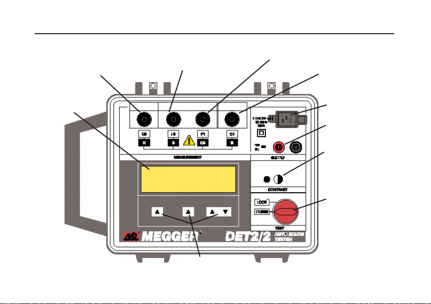
Features and Controls
To Current test spike
To Potential test spike
To electrode under test
(Potential connection)
To electrode under test
(Current connection)
31⁄2 digit L.C.D.
6
Charger socket
External 12 V d.c.
supply Terminals
Display contrast
adjustment
On / Off Test Button
(Rotate clockwise
to lock)
Test control
switches
Page 7

Initial Configuration
Default Language Setting
Select and set the display language default as follows:
1. Press the left hand key ▲ and the TEST button
together. Rotate the TEST button clockwise to the
lock position. The language options are displayed.
2. Adjust the display contrast as necessary.
3. Using the centre ▲ key, scroll through the
language options. When the required language is
highlighted with a box surround, press the left
hand ▲ key. The test frequency options are
displayed.
Default Frequency Setting
Default test frequencies are available as follows:-
108 Hz - For use when testing with interference
frequencies in the vicinity of 16 Hz.
128 Hz - For use when testing with interference
frequencies in the vicinity of 50 Hz.
135 Hz -
150 Hz - For use when testing with interference
frequencies in the vicinity of 60 Hz.
For each default value, the test frequency range can be
incremented in 0,5 Hz steps from 105 Hz to 160 Hz;
using the ▲ ▼ keys.
Select and set the default Frequency as follows:
1. Using the centre ▲ key, scroll through the
Frequency options. When the required Frequency
is highlighted with a box surround, press the left
hand ▲ key. The Test and Calibration mode
options are displayed. The message “Please
wait...” is displayed.
Saving the Test Parameter settings
The settings made for Test current and filtering options,
and the Frequency of the Test current may be saved for
use in subsequent tests as follows:
1. After making the settings, press and hold the ▲
Scroll key during the measuring mode. The
display lists the default selection.
2. Accept the settings and press the ▲ Yes key, or
press the ▲ No key to cancel.
Once accepted, further tests may, if desired be carried
out with different settings. The instrument will default to
the saved settings if switched Off and back On again.
7
Page 8

Setting up the Test spikes
For earth electrode testing and for earth resistivity
surveying, the instrument’s test leads are connected to
spikes inserted in the ground. The way the connections
are made depends on the type of test being undertaken
and details are given in ‘Measuring Techniques’.
Test spikes and long test leads are necessary for all
types of earth testing and the optional earth testing field
accessory kits contain the basic equipment. See
‘Accessories’.
1. Insert the Current test spike into the ground 30 to
50 metres away from the Earth electrode to to be
tested.
2. Connect this spike to the instrument terminal 'C2'
(‘H’).
3. Insert the Potential test spike into the ground
midway between the Current test spike and the
Earth electrode, and in direct line with them both.
4. Connect this spike to the instrument terminal 'P2'
(‘S’).
5. When running the test leads out to each remote
electrode, avoid laying the wires too close to each
other.
8
Page 9
Earth Testing Safety Precautions
Electrode Isolation or Duplication
It is preferable that the earth electrode to be tested is
first isolated from the circuit it is protecting, so that only
the earth is measured and not the complete system.
When this is done, the circuits and equipment must be
de-energised. If however this is not possible, the earth
electrode should be duplicated, so that when it is
disconnected for test purposes, the other one provides
the necessary circuit protection.
‘Live’ earth safety precautions
The DET2/2 allows earth testing to be done at a
relatively safe voltage using a maximum of a 50 V RMS
square wave at a frequency of nominally 128 Hz. In use
it is normally connected only to electrodes which are at
earth potential.
A 'Live' earth is one that carries current from the mains
supply, or could do so under fault conditions.
When working around power stations or sub stations
there is a danger that large potential gradients will
occur across the ground in the event of a phase to earth
fault. A wire which is connected to ground many metres
away will then no longer be at the same potential as
local ground, and in some cases could rise to above
1 kV. The following safety precautions are essential.
1. All persons involved must be trained and
competent in isolation and safety procedures for
the system to be worked on. They must be
clearly instructed not to touch the earth
electrode; test spikes; test leads, or their
terminations if any 'Live' earths may be
encountered. It is recommended that persons
involved wear appropriate rubber gloves, rubber
soled shoes, and stand on rubber mats.
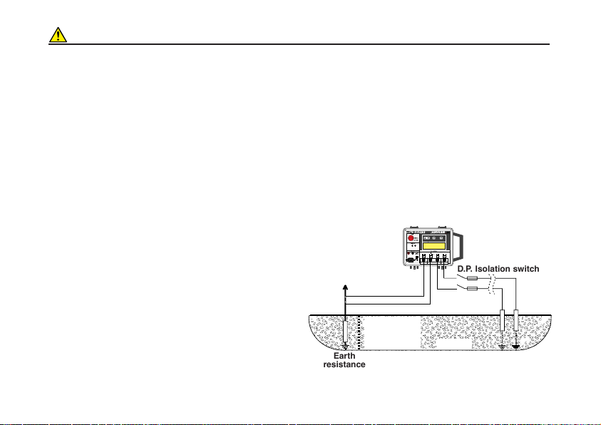
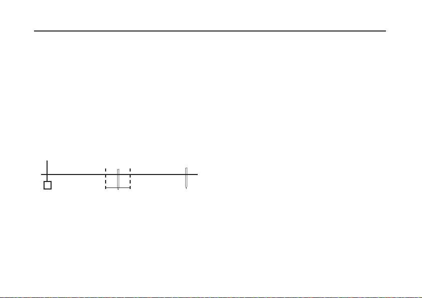
2. The 'P2' and 'C2' terminals should be connected
through a double pole isolation switch, the rating
of which will cope with the maximum fault
voltage and current. The isolation switch must
be open whilst any personal contact is made
with the remote test spikes, or the connecting
leads, e.g. when changing their position.
Fault
current
Voltage rise of
earthing system
under fault
conditions
Earth
resistance
A method of disconnection where fault conditions
may occur.
D.P. Isolation switch
Fuses
True earth
Remote
spikes
9
Page 10

Earth Testing Safety Precautions
If isolation switches cannot be used, the leads should
be disconnected from the instrument before remote
spikes and leads are handled. When the remote
connections have been made, the final connections
should be made to the instrument using insulated
plugs, ensuring that the Operator takes adequate and
appropriate precautions such as insulating mats,
rubber gloves etc.
If a fault occurs while a test is being made the
instrument may be damaged. Incorporating fuses
(rated at 100 mA and able to cope with the maximum
fault voltage) at the isolation switch will provide some
protection for the instrument.
Caution: When working on live sites, do not use an
external battery to power the instrument, as this would
also become live under fault conditions.
10
Page 11

Operation
It is advisable that the battery of the DET2/2 is fully
General T
charged before embarking on a test sequence. It can
be extremely inconvenient if the battery becomes too
low while a field test is in progress.
1. Firmly connect the instrument terminals to the
respective earth electrode and test spikes. See
‘Setting up the Test spikes‘ and ‘Measuring
Techniques‘.
2. Press and hold the On/Off push button, or rotate it to
the Lock position.
3. If required, carry out a Pspike test to check
continuity of the the Potential circuit.
4. The resistance value being measured is shown on
the sub display after a few moments, when the
“Please wait...” message has disappeared.
T
If the sub display message states that a true
measurement cannot be obtained, the test conditions
esting Procedure
est Condition Adjustments
can be altered to achieve optimum conditions for the
test. One or more of the following may be used:-
Test current Frequency
Using the right hand ▲ or ▼ keys, increase or decrease
the test current frequency range. See ‘Initial
Configuration and Spike set up‘.
Lo Current /Hi Current
Using the centre ▲ key, scroll through the left hand
options to select and highlight the ‘Current‘ option.
Press the left hand ▲ key to toggle between ‘Lo
Current‘ and ‘Hi Current‘. ‘Hi Current‘ assists to
overcome problems caused by high current spike
resistance. Note: Current circuit resistance is
constantly monitored during a test. If too high, a
message to this effect is displayed.
Filter
Using the centre ▲ key, scroll through the left hand
options to select and highlight the ‘Filter‘ option.
Press the left hand s key to toggle between ‘Filter off‘
and ‘Filter on‘. ‘Filter on‘ assists to reduce ‘noise‘
affecting the reading. The time taken to make a
measurement increases significantly with ‘Filter on‘.
PSpike
Using the centre ▲ key, scroll through the left hand
options to select and highlight the ‘Pspike‘ option.
Press the left hand ▲ key to automatically carry out a
11
Page 12

Operation
resistance check of the of the Potential circuit. After a
short pause, the result of this check is displayed on the
sub panel. If appropriate, the ‘Pspike‘ label then
changes to ‘Retest’, giving the option to repeat the test
after any alteration to spike position etc. has been
made. Press the centre ▲ key, now labelled ‘Measure’
to repeat the measurement.
Note: If for any reason a test is made with an open
Potential circuit, the resultant test reading will be
invalid. To confirm that connections are still in place
and to check the validity of the test, a ‘P spike‘ check
should be made before each test.
Auto Ranging
If the earth resistance being measured is low, but a
high level of ’noise’ is present, coupled with a high
Current spike resistance, the instrument will
automatically make a measurement with a lower
precision. If successful, the resistance reading will be
displayed with only 3 digits, the least significant digit
being blanked out.
Greater precision can be obtained by:-
a) Reducing spike resistance (e.g. by wetting the
ground, or by inserting the spikes deeper into the
ground).
b) Toggling to ‘Hi Current‘ option.
c) Eliminating the ‘noise’ source if possible.
12
Displa
When appropriate, messages are displayed. The
following message definitions are given:
This means that the instrument is making internal
measurements and tests before displaying the
resistance reading. The ▲ and ▼ keys remain active
and measurement conditions may be adjusted before
a reading is displayed. These messages may be
repeatedly displayed if there is a high ‘noise’ level
present, close to the frequency of the measurement,
or if the Potential circuit is incorrectly connected.
“Open Circuit Current Terminals”
This means that the test current flowing is low, and
implies that a resistance of >500 kΩ is present between
the test terminals. If this message remains displayed
when terminals ‘C1‘ and ‘C2‘ are shorted together, an
internal fuse has ruptured, with the possibility of other
internal damage having been caused. In this case,
return the instrument, return the instrument to the
manufacturer or an approved repair company. See
’Repair and Warranty’.
“Check connections voltage terminals”
This message is displayed when the connections to the
‘P1‘ and ‘P2‘ connections are reversed. Check and
correct as necessary.
y Messages
“Please wait...”
“Please wait... zeroing”
Page 13

“High current noise”
“High voltage noise”
These messages are displayed when the noise voltage
present is greater than the acceptable level, causing
the measurement to be invalid. Changing the test
frequency will have no effect in this instance. If
possible, eliminate the noise source, or reduce spike
resistance (e.g. by wetting the ground, or by inserting
the spikes deeper into the ground).
Further Display Messages
High level of interference or an instrument fault could
cause the display of any of the following messages:
“Invalid current”
“Invalid voltage”
“Invalid current zero”
“Invalid voltage zero”
“Current zero too big”
“Voltage zero too big”
“Noisy current zero”
“Noisy voltage zero”
Incorrect connection of the potential terminals could
cause an ‘Invalid voltage’ message.
Err
Error messages may appear on the bottom line of the
display in the event of a instrument or software fault, or
due to the existence of adverse electrical conditions. If
an error message appears, switch the DET2/2 off,
refer to ‘Repair and Warranty’ and return the
instrument to the manufacturer or approved agent,
giving details of the error message and the software
edition.
If calibration data stored in the instrument has been
incorrectly retrieved, the above message is displayed
(in English) when switching on. Switch the DET2/2
off, refer to ’Repair and Warranty’ and return the
instrument to the manufacturer or approved agent,
giving details of the error message and the software
edition.
Default language, frequency and current level are
normally retrieved when the instrument is switched on.
If unsuccessful, the above message is displayed (in
English) when switching on, with the option to “Retry”
(try reading the data again) or “Manual” (manually set
up the data again). If ‘Retry’ or ‘Manual’ is
or Messages
“Calibration data retrieval error
Refer to handbook”
“Setup data retrieval error”
13
Page 14

Operation
unsuccessful, switch the DET2/2 off, refer to ’Repair
and Warranty’ and return the instrument to the
manufacturer or approved agent, giving details of the
error message and the software edition.
14
Page 15

Battery Charging
Battery capacity
The capacity of the battery is continuously monitored
and displayed, adjacent to the battery symbol. The
indicator segments will show fully charged, or recede
as the battery is used, to indicate three quarters full,
half full or quarter full. A warning message is displayed
if the battery is unable to supply adequate test current.
Charging method
It is advisable that the battery is fully charged before
embarking on a test sequence. Charging is carried out
by external a.c. mains supply only. Charging
commences automatically as soon as the supply is
connected. Normal recharge time is 6 hours. Testing is
inhibited during charging.
Battery charging requires a supply voltage of 100 V to
130 V a.c., or
to a voltage from 130 V to 200 V will not cause harm,
but will not charge the battery, and the message
“Power Supply too low” will be displayed. Charging
time will be extended if either the power supply voltage
drops too low during the charge period or if the battery
has been excessively discharged. Charge the battery
as follows:
1. Switch the Test switch to Off.
2. Remove any connections to the 4 mm external
supply sockets.
200 V to 260 V, 50 - 60 Hz. Connection
3. Disconnect and remove the test leads.
4. Connect the mains supply to the IEC 320
connector on the top right of the instrument.
Confirm that the message “Charging On” is
displayed. Progressive and accumulated charging
times are displayed.
5. When fully charged, the charging current will
automatically reduce to ”Trickle Charge“.
Charging will automatically stop after a period of
24 hours.
Note: The battery will be prevented from charging if an
external battery is connected to the 4 mm sockets
during the charging process. An external connected
battery cannot be charged via the instrument.
15
Page 16

Battery Charging
Battery Charging Power cord plug
If the power cord plug is not suitable for your type of
socket, do not use an adaptor. You should use a
suitable alternative power cord, or if necessary, change
the plug by cutting the disconnected cord and fitting a
suitable plug.
The colour code of the cord is:-
Earth (Ground) - Yellow/Green
Neutral - Blue
Phase(Line) - Brown
If using a fused plug, a 3 amp fuse to BS 1362 should
be fitted.
Note: A plug severed from the power cord should be
destroyed, as a plug with bare connections is
hazardous in a live socket outlet.
16
Battery Charging Notes
1) Do Not leave battery in a totally discharged state.
If the instrument is idle for long periods, recharge
the battery at least every 6 months. (More
frequently if the storage temperature is >40 °C).
2) Battery charging should be carried out in a dry
environment and at temperatures in the range 0 °C
to 40°C.
3) When charging the battery indoors, the area
should be well ventilated.
Page 17
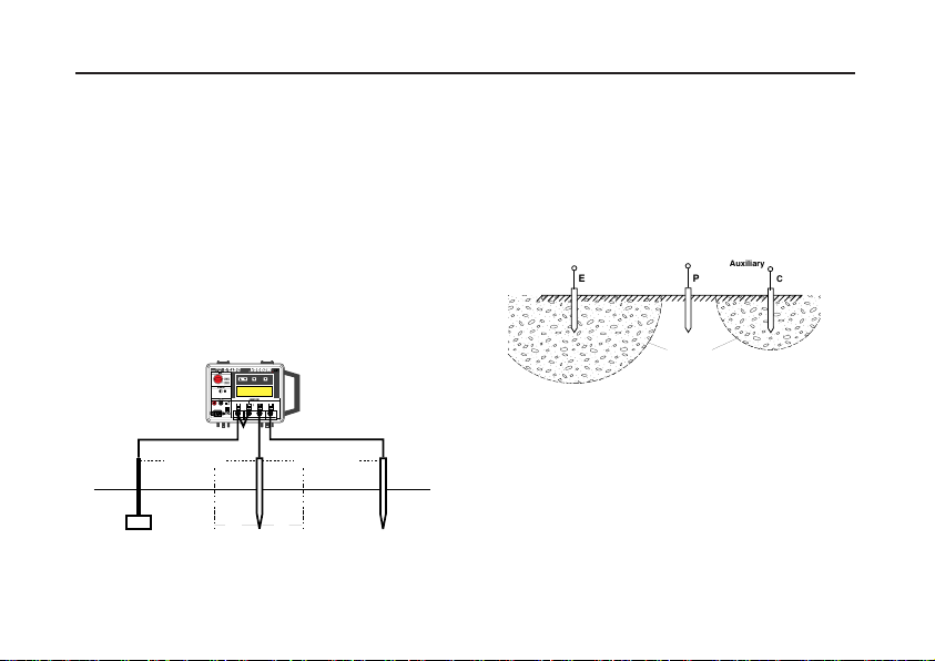
Measuring Techniques - Testing Earth Electrodes
Electrode
under test
Potential
spike
3m 3m
15m to 25m 15m to 25m
Current
spike
FALL-OF-POTENTIAL METHOD
This is the basic method for measuring the resistance
of earth electrode systems. However, it may only be
practical on small, single earth electrodes because of
limitation on the size of area available to perform the
tests.
Insert the Current test spike into the ground some 30 to
50 metres away from the earth electrode to be tested.
Firmly connect this spike to the instrument terminal 'C2'.
Insert the Potential test spike into the ground midway
between the Current test spike and the earth electrode.
Firmly connect this spike to the instrument terminal
'P2'.
Note:- It is important that the Current spike, the
Potential spike and the earth electrode are all in a
straight line. Also when running the test leads out to
each remote spike, it is preferable not to lay the wires
close to each other in order to minimise the effect of
mutual inductance.
Firmly connect the 'C1' and the 'P1' instrument
terminals to the earth electrode as shown.
Operate the instrument as explained in 'Basic Test
Procedure', and note the resistance obtained.
Move the potential spike 3 metres further away from the
earth electrode and make a second resistance
measurement. Then move the potential spike 3 metres
nearer the electrode (than the original position) and
make a third resistance measurement. If the three
resistance readings agree with each other, within the
required accuracy, then their average may be taken as
the resistance to earth of the electrode. If the readings
disagree beyond the required accuracy then an
alternative method should be used e.g. the 61,8% Rule
or the Slope Method etc.
Fall-of-Potential method connections.
17
Page 18
Measuring Techniques - Testing Earth Electrodes
Fall-of-Potential Method with Short 'E' Lead
Another way of making connections to the earth
electrode is to connect to the earth electrode using only
one single connection to the ‘C1’ terminal. This should
only be done if the test lead can be kept short because
its resistance will be included in the measurement.
Note:- Earth electrode test lead resistance can be
determined separately. First remove it from the the
electrode and connect to the 'C2' and 'P2' terminals.
Press the Test push button. The lead resistance can
then be deducted from the earth resistance
measurements. This procedure is not, of course,
necessary if the 'C1' and 'P1' terminals are connected
by separate test leads.
15m to 25m 15m to 25m
Electrode
under test
Fall-of-Potential method using a single lead to the
3m 3m
Potential
spike
Current
spike
earth electrode.
18
THE 61,8% RULE
To obtain an accurate reading using the Fall-ofPotential method the current spike must be correctly
sited in relation to the earth electrode. Since both
possess ‘resistance areas’, the Current spike must be
sufficiently remote to prevent these areas overlapping.
Furthermore, the Potential spike must be between
these areas. If these requirements are not met, the Fallof-Potential method may give unsatisfactory results.
Electrode
EPC
Under Test
Resistance areas associated with an earth
electrode and current spike.
Theoretically, both the Current and Potential spikes
should be at an infinite distance from the earth
electrode. However, by graphical considerations and by
actual test it can be demonstrated that:-
The ‘true’ resistance of the earth electrode is equal to
the measured value of resistance when the Potential
spike is positioned 61,8% of the distance between the
earth electrode and the Current spike, away from the
earth electrode.
Auxiliary
Potential
Electrode
Resistance Areas
(Not Overlapping)
Auxiliary
Current
Electrode
Page 19

This is the 61,8% Rule and strictly applies only when
Electrode
under test
Potential
spike
Current
spike
61,8% of EC
38,2% of EC
the earth electrode and Current and Potential spikes lie
in a straight line, when the soil is homogeneous and
when the earth electrode has a small resistance area
that can be approximated by a hemisphere. Bearing
these limitations in mind this method can be used, with
care, on small earth electrode systems consisting of a
single rod or plate etc. and on medium systems with
several rods.
Connections for the 61,8% Rule.
For most purposes the Current spike should be 30
metres to 50 metres from the centre of the earth
electrode under test. The Potential spike should be
inserted in the ground 61,8% of this distance, between
and in a straight line with, the Current spike and the
earth electrode. The distance is measured from the
earth electrode. If the earth electrode system is of
medium size containing several rods, then these
distances must be increased. The following table gives
a range of distances that agree with the rule. In the first
column ‘Maximum dimension’ is the maximum
distance across the earth electrode system to be
measured.
Maximum
dimension
in metres
5
10
20
Distance to Potential
spike in metres from
centre of earth
system
62
93
124
Distance to Current
spike in metres from
centre of earth
system
100
150
200
For greater accuracy an average reading can be
calculated by moving the current spike, say 10 metres,
towards and then away from its first position and
making further resistance measurements. (Remember
that the Potential spike must also be moved in
accordance with the 61,8% Rule). The average of the
three readings can then be calculated.
19
Page 20

Measuring Techniques - Testing Earth Electrodes
P
C
Electrode
under test
EC
Position of Electrode P
measured from E
Arbitrary position
of Earth electrode
0,2 EC 0,4 EC
0,6 EC
Position of
C electrode
Earth
resistance
curve
R3
R2
R1
Resistance
20
THE SLOPE METHOD
This method is more applicable to larger earth
electrode systems or where the position of the centre of
the earthing system is not known or inaccessible (e.g.
if the system is beneath the floor of a building). The
Slope method can also be used if the area available for
siting the earth electrodes is restricted. It can be tried if
the previous methods prove unsatisfactory and
generally yields results of greater accuracy than those
methods.
Connections for the Slope method
The equipment is set up as shown. The remote Current
spike is placed 50 metres or more from the earth
electrode system to be measured and connected to the
'C2' terminal. The Potential spike is inserted at a
number of positions consecutively, between the earth
system and the Current spike, and connected to the
'P2' terminal. The test spikes and the earth system
should all be in a straight line.
The 'C1' and 'P1' terminals are connected separately
to some point on the earth electrode system.
The earth resistance is measured at each separate
position of the Potential spike and the resistance curve
is plotted from the results. At least six readings are
needed. Drawing the curve will show up any incorrect
points which may be either rechecked or ignored.
Example Resistance curve from Slope method
tests.
Page 21

Suppose the distance from the earth electrode system
to the current spike is EC. From the curve equivalent
resistance readings to Potential positions 0,2EC, 0,4EC
and 0,6 EC can be found. These are called R1, R2 and
R3 respectively.
Calculate the slope coefficient μ, where
μ = (
which is a measure of the change of slope of the earth
resistance curve.
From the table commencing on page 36 obtain the
value of Pt / Ec for this value of μ.
Ptis the distance to the Potential electrode at the
position where the ‘true’ resistance would be
measured.
Multiply the value of Pt / Ec by Ec to obtain the distance
Pt.
From the curve read off the value of resistance that
corresponds to this value of Pt. The value obtained is
the earth electrode system's resistance.
Note:- (i) If the value of μ obtained is not covered in
the table then the current spike will have to be moved
further away from the earthing system.
R3-R2
(R2-R1)
)
(ii) If it is necessary, further sets of test results can be
obtained with different values of EC, or different
directions of the line of EC. From the results obtained of
the resistance for various values of the distance EC.
Example of possible results from several Slope
method tests.
This shows how the resistance is decreasing as the
distance chosen for EC is increased.
The curve indicates that the distances chosen for EC in
tests (1) and (2) were not large enough, and that those
chosen in tests (3) and (4) were preferable because
they would give the more correct value of the earth
resistance.
(iii) It is unreasonable to expect a total accuracy of
more than 5%. This will usually be adequate, bearing in
mind that this sort of variation occurs with varying soil
moisture conditions or non-homogeneous soils.
21
Page 22

Measuring Techniques - Testing Earth Electrodes
E
Electrode
under test
METHOD USING A ‘DEAD’ EARTH
The techniques using test spikes explained earlier are
the preferred methods of earth testing. In congested
areas it may not be possible to find suitable sites for the
test spikes, nor sufficient space to run the test leads. In
such cases a low resistance conductive water main
may be available. This is referred to as a ‘dead’ earth.
Great care must be taken before deciding to adopt this
method and its use is not to be encouraged. Before
employing this method, the user must be quite sure that
no part of the ‘dead‘ earth installation contains plastic or
other non-metallic materials.
1) Short together terminals ‘P1’ and ‘C1’.
2) Short together terminals ‘P2’ and ‘C2’.
2) Firmly
connect a test lead to ‘C1‘ and ’P1‘ and the
other test lead to ‘P2‘ and ‘C2‘.
3) Firmly
connect the free ends of the test leads
to the ‘dead’ earth, and to the electrode under test.
4) Press the Test push, and take a reading in
the normal way.
This test will give give the combined resistance to earth
of the two earths in series. If that of the ‘dead‘ earth is
negligible then the reading may be taken as that of the
electrode under test .
22
The resistance of the two test leads can be found by
firmly joining their free ends together, pressing the Test
push and taking the reading in the usual way. Test lead
resistance can then be subtracted from the original
reading, to obtain the combined resistance of the earth
electrode and the ‘dead’ earth.
In congested urban areas, the Star-Delta method is the
preferable. This method is explained along with other
methods referred to, in ‘Getting Down to Earth’ (see
‘Accessories‘ - Publications).
‘Dead’ earth testing
Page 23
BS7671(16th Edition wiring regulations)
requirements
Regulation 713-11 of BS7671 specifies that the
resistance of earth electrodes must be measured. The
accompanying Guidance Notes describe a method of
test that is very similar to the Fall-of-Potential method.
If the maximum deviation from the average of the three
readings is better than 5% then the average can be
taken as the earth electrode resistance. If the deviation
exceeds 5% then the current spike should be moved
further away from the electrodes and the tests
repeated.
Other Methods
There are other methods of earth electrode testing
among which are the Four Potential, Intersecting Curves
and Star Delta methods. Megger Limited publications
explain these test methods and give other helpful
information about earth testing. See ‘Accessories‘ -
Publications.
E
6m
P
6m
Test spike positions for BS7671 testing
C
23
Page 24
Measuring Techniques - Testing Earth Electrodes
Earth
1m
Potential
spike
Current
spike
Earthed Perimeter Fence
SUBSTATION
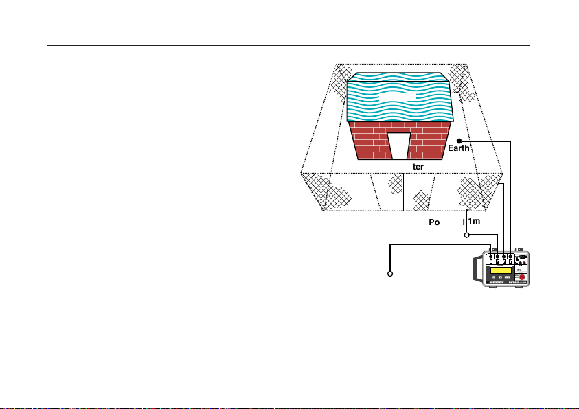
Determining ‘Touch’ Potential
‘Touch’ potential is the potential difference a person
would experience across his body if he were, for
example, standing on the ground outside the earthed
perimeter fence of a substation and touching the fence
at the time a fault occurred.
Firmly connect the instrument as follows:-
1) Terminal 'C1' to the substation earth.
2) Terminal 'C2' to the Current spike inserted in the
ground some distance away.
3) Terminal 'P1' to the structure being tested e.g. the
perimeter fence.
4) Terminal 'P2' to the Potential spike inserted in the
ground 1 metre away from the perimeter fence
adjacent to the point where a person might stand.
5) Press the Test push, and take a reading in
the normal way. This is the effective resistance
between the point of test on the fence and the
Potential spike as seen by the test current.
The maximum value of the current that would flow in
the earth when a fault to earth occurred at the
substation must be known. The maximum fault current
has to be calculated from the parameters associated
with the substation ratings involved. From Ohms Law
(V = I x R), the Touch potential can be calculated.
24
Determining 'Touch' potential.
Page 25

Determining ‘Step’ potential
Earth
Current
spike
SUBSTATION
1m
A
B
‘Step’ potential is the potential difference a person
would experience between his feet as he walked across
the ground in which a fault current was flowing.
Firmly connect the instrument as follows :-
1) Terminal 'C1' to the substation earth.
2) Terminal 'C2' to the Current spike inserted in the
ground some distance away.
3) Firmly connect the 'P1' and 'P2' terminals to test
spikes inserted in the ground 1 metre apart, (or the
length of a step) at positions A and B respectively.
A is nearest to the substation earth.
4) Press the Test push, and take a reading in
the normal way.
Record the resistance indicated. This is the effective
resistance across the positions A and B, as seen by the
test current.
The maximum value of the current that would flow in
the earth when a fault to earth occurred at the
substation must again be known. From Ohms Law the
‘Step potential’ can be calculated.
Determining ‘Step’ potential
25
Page 26

Measuring Techniques - Measuring Soil Resistivity
Typical variations in soil resistivity
The resistance to earth of an earth electrode is
influenced by the resistivity of the surrounding soil. The
resistivity depends upon the nature of the soil and its
moisture content and can vary enormously as seen in
the table below:-
Material
Ashes
Coke
Peat
Garden earth - 50% moisture
Garden earth - 20% moisture
Clay soil - 40% moisture
Clay soil - 20% moisture
London clay
Very dry clay
Sand - 90% moisture
Sand - normal moisture
Chalk
Consolidated
Sedimentary rocks
Specific
resistance
in Ω-cms
20 - 800
4500 - 20000
400 - 2000
5000 - 15000
13000
300000 - 800000
5000 - 15000
1000 - 50000
350
1400
4800
770
3300
Information
source
Higgs
Ruppel
Ruppel
Ruppel
Ruppel
Broughton
Edge & Laby
26
Because it is impossible to forecast the resistivity of the
soil with any degree of accuracy it is important to
measure the resistance of an earth electrode when it is
first laid down and thereafter at periodic intervals.
Before sinking an electrode into the ground for a new
installation it is often advantageous to make a
preliminary survey of the soil resistivity of the
surrounding site. This will enable decisions to be made
on the best position for the electrode(s) and to decide
whether any advantage can be gained by driving rods
to a greater depth. Such a survey may produce
considerable savings in electrode and installation costs
incurred trying to achieve a required resistance.
Page 27
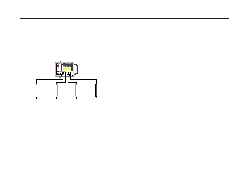
Line Traverse
a
a
a
P1
a
20
The most common method of measuring soil resistivity
is often referred to as the line traverse. Four test spikes
are inserted into the ground in a straight line at equal
distances 'a' and to a depth of not more than 1/20 of 'a'.
The instrument is connected to the test spikes as
shown.
Soil resistivity measurement.
The instrument is operated and the measurement
made in the normal way. The resistivity may be
calculated from the formula given opposite or from the
nomogram overleaf. This is the average soil resistivity
to a depth 'a'.
The four test spikes are then re-positioned for further
tests along a different line. If both the spacing 'a' and
the depth a/20 are maintained, a directly comparable
reading will be obtained each time, and thus regions of
lowest resistivity can be located over a given area (at
the constant depth 'a').
Re-spacing the test spikes at separations 'b', 'c', 'd', etc
will yield results from which a profile of the resistivity at
new depthsb/20, c/20, d/20,etc.can be obtained.
If the same line for the test spikes is maintained, but the
separation of them is progressively widened, resistivity
values at various depths can be obtained. By this
means depth surveys may be made.
More details can be found in the Megger Limited
publications. See ‘Accessories‘.
Calculation of resistivity
Assuming that the tests were carried out in
homogeneous soil the resistivity is given by the
formula:-
ρ = 2πaR
where ‘R’ is the resistance measured in ohms, ‘a’ is the
test spike spacing in metres and ‘ρ’ is the resistivity in
ohm-metres.
For non-homogeneous soils the formula will give an
apparent resistivity which is very approximately the
average value to a depth equal to the test spike spacing
'a'.
27
Page 28

Measuring Techniques - Measuring Soil Resistivity
Resistivity calculation Nomogram
28
Page 29
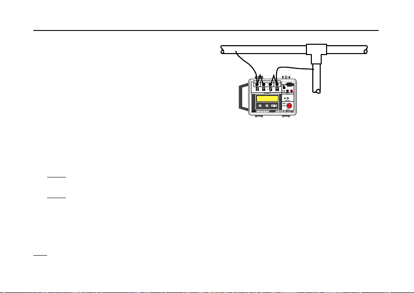
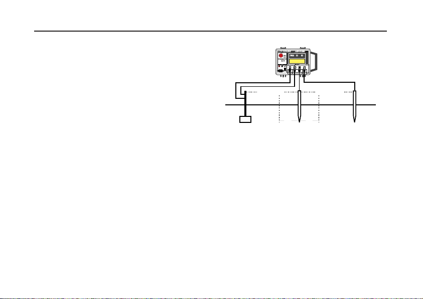
Measuring Techniques - Continuity Testing
DET 2/2 can be used to measure metallic resistances
of low inductance or capacitance. To test the continuity
of conduit or other earth conductors the instrument can
be connected as shown. Ensure that the circuit is deenergised, before connecting the instrument for
measurement.
Note:- Due to the inherent high accuracy of the
instrument and the low continuity resistance to be
measured, contact resistance between the test lead
clips and the conduit becomes a factor in the measured
value. Contact resistance should therefore be kept as
low as possible.
1) Firmly short together terminals ‘P2’ and ‘C2’.
2) Firmly short together terminals ‘P1’ and ‘C1’.
3) Firmly
4) Firmly
5) Press the Test push, and take a reading in the
The resistance of the two test leads can be found by
firmly joining their free ends together, pressing the
T
est push and taking the reading in the usual way. Test
lead resistance can then be subtracted from the original
reading, to give a ‘true’ value of continuity resistance.
connect a test lead to ‘P2 and C2’,and the
other test lead to ‘P1’ and ‘C1’.
connect the free ends of the test leads
across the isolated circuit under test.
normal way.
Continuity testing.
29
Page 30

Specification
Earth Resistance Ranges: 0,010 Ω to 19,99 kΩ (Auto-ranging) 1 mΩ resolution
Accuracy (23°C ±2°C): ±0,5% of reading ±2 digits. Service error ±5% of reading ±2 digits ±10 mΩ
Test Frequency: 105 Hz to 160 Hz reversing d.c. (50 Hz environments default to 128 Hz,
Test Current: 50 mA max. (selectable high and low levels)
Max Output Voltage: < 50 V r.m.s.
Interference: Typically 40 V pk to pk (50 Hz, 60 Hz, sinusoidal nature)
Max. Current spike
(Loop) Resistance: Range (R
Max. Potential Spike Resistance: Range (R
30
(meets VDE service error over 50 mΩ)
60 Hz environments default to 150 Hz). Set in steps of 0,5 Hz
) High current (Rp) Low current (Rc)
0,010 Ω - 0,499 Ω 5 kΩ 1 kΩ
E
0,500 Ω - 1,999 Ω 5 kΩ 3 kΩ
2,000 Ω - 19,99 Ω 10 kΩ 5 kΩ
20,000 Ω - 199,9 Ω 50 kΩ 20 kΩ
200, 0 Ω - upwards 50 kΩ 50 kΩ
) High current (Rp) Low current (Rp)
E
0,010 Ω - 0,499 Ω 1 kΩ 10 kΩ 1 kΩ 10 kΩ
0,500 Ω - 1,999 Ω 1 kΩ 20 kΩ 1 kΩ 10 kΩ
2,000 Ω - 19,99 Ω 1 kΩ 20 kΩ 1 kΩ 10 kΩ
20,000 Ω - 199,9 Ω 200 x R
200, 0 Ω - upwards 50 kΩ total 50 kΩ total
(Rp1) (Rp2)(R
E 20 kΩ 200 x RE 20 kΩ
) (Rp2)
p1
Page 31

Display: Alpha numeric LCD (130 mm x 35 mm) giving test information and a large
(20 mm) 3
1
⁄2 digitLCD, maximum reading 1999
Instrument Protection: Meets the general requirements of IP54
Temperature Effect: <±0,1%/°C over the temperature range -10°C to +40°C
Temperature Range: Operating: -10°C to +40 °C
Storage: -20°C to +60°C
Humidity: Operating: 90% RH max. at 40°C
Flash Test: 3 kV a.c.
Voltage Withstand: In the event of a system fault the instrument will withstand 240 V a.c.
applied between any two terminals.
Compliance with Standards: BS 7430 (1992) BS7671 (1992) NFC 15-100
VDE 0413 Part 7 (1982) IEC364
Power Supply: (i) Internal rechargeable sealed lead acid cells 12 V nominal, 2,6 Ah
capacity. Battery voltage range over which basic accuracy is
maintained, 11,0 V to 13,5 V.
Battery life: Typically 5 Hours continuous use
Battery charging time: 6 hours max. (from completely exhausted).
Charging supply required: 100 V to 130 V or 200 V to 260 V a.c. 50 Hz/60 Hz.
Power consumption: 25 VA
31
Page 32

Specification
Note: When the battery is charging, fast transients can cause the display to go blank. This will not normally affect
the charging operation.
Fuses (Non replaceable):
Mains supply protection: 200 mA (T) ceramic HBC 20 mm x 5 mm to IEC 127/3
Battery protection: 2 A (T) ceramic HBC 20 mm x 5 mm to IEC 127/3
Battery in-line protection: 3,15 A (T) ceramic HBC 20 mm x 5 mm IEC 127/3
External 12 V supply protection: 2 A (T) ceramic HBC 20 mm x 5 mm IEC 127/3
Output current protection: 80 mA (F) glass 20 mm x 5 mm
Fuse (Replaceable):
Mains power cord fused plug: 3 Amp fuse to BS 1362
Safety: Meets the requirements for safety to IEC 61010-1
E.M.C: In accordance with IEC61326-1
Operational uncertainties: Visit www.megger.com
Dimensions: 344 mm x 245 mm x 158 mm
Weight: 5 kg
Cleaning: Wipe the disconnected instrument with a clean cloth dampened with
32
(ii) External 12 V d.c. source
soapy water or Isopropyl Alcohol (IPA).
Page 33

VDE 0413 part 7 specification stipulates that these
instructions should contain a table or diagram showing
the maximum value which the instrument must indicate
in certain conditions. An earth test being performed on
any electrode system would normally be carried out to
a particular specification. Therefore, even at the iworst
accuracy of the instrument, the reading is never above
the limiting value required by the particular
specification in question.
The table overleaf shows the maximum reading which
shall be indicated by the instrument (at its maximum
error) to ensure that the maximum value of the earth
resistance given in the relevant earth electrode test
specification is met.
Note: The decimal point position in the Maximum
Resistance value column is correct for resistance
readings < 2 Ω. For the 2 Ω to 20 Ω column and the >
20 Ω column, the decimal point should be moved
accordingly. For maximum readings in excess of 200 Ω
use the right hand column and adjust the decimal point
accordingly.
The table gives the maximum reading that would be
allowed for a known maximum resistance value,
assuming the instrument is used as specified.
If a maximum resistance is known, this value is found
from the left hand column. The maximum reading to be
given by the instrument is found by reading across to
the appropriate of the three right hand columns,
depending upon the range of the value to be measured.
For example If 10 Ω is the value of the maximum
resistance, since this is less than 20 Ω, the centre
column of the three right hand columns is used. This
shows that a reading of less than 9,49 Ω will ensure
that, allowing for instrument tolerances, the measured
resistance will be less than 10 Ω.
A maximum value may be given to a measurement by
using the table in reverse. For example, a reading of
1,545 Ω would give a maximum limit to the resistance
value of between 1,600 Ω and 1,650 Ω. Interpolation
can be used to increase the accuracy if required.
Note: This table can only be used for readings from a
DET2/2.
33
Page 34

Specification
Maximum
Resistance
Value
0,050 -0,036 0,100 -0,083 0,150 -0,131 0,200 18,80,179 1,88
0,250 23,60,226 2,35
0,300 28,30,274 2,83
0,350 33,10,321 3,30
0,400 37,90,369 3,78
0,450 42,60,417 4,26
0,500 47,40,464 4,73
0,550 52,10,512 5,21
0,600 56,90,560 5,68
0,650 61,70,607 6,16
0,700 66,40,655 6,64
0,750 71,20,702 7,11
0,800 76,00,750 7,59
0,850 80,70,798 8,07
0,900 85,50,845 8,54
0,950 90,20,983 9,02
1,000 95,00,940 9,49
1,050 99,80,988 9,97
34
Maximum Reading Maximum
< 2
2 to 20
> 20
Resistance
Value
1,100 104,51,036 10,45
1,150 109,31,083 10,92
1,200 114,01,131 11,40
1,250 118,81,179 11,88
1,300 123,61,226 12,35
1,350 128,31,274 12,83
1,400 133,11,321 13,30
1,450 137,91,369 13,78
1,500 142,61,417 14,26
1,550 147,41,464 14,73
1,600 152,11,512 15,21
1,650 156,91,560 15,69
1,700 161,71,607 16,16
1,750 166,41,655 16,64
1,800 171,21,702 17,11
1,850 176,01,750 17,59
1,900 180,71,798 18,07
1,950 185,41,845 18,54
2,000 190,21,893 19,02
2,050 195,01,940 19,50
21,00 199,81,988 19,97
Maximum Reading
< 2
2 to 20
> 20
Page 35

Accessories
SUPPLIED Part Number
User Guide 6171-428
Battery charging Power cord
OPTIONAL
Publications
‘Getting Down to Earth’ AVTM25-TA
Four Terminal Earth Testing kit 6310 - 755
Carrying bag containing:Club hammer, 4 x spikes, two spike
extractors, 3m (x2) cable and 30m,
50m of cable on winders.
Four Terminal Compact Earth 6210 - 161
Testing kit
Compact carrying bag containing:2 x push in spikes, 3m, 15m, 30,
and 50m of cable on cable tidy.
Three Terminal Compact Earth 6210 - 160
Testing Kit
Compact carrying bag containing:2 x push spikes, 3m, 15m and 30m
of cable on a cable tidy.
U.S. OPTIONS Cat. Number
Standard Accessory kit 250579
Canvas case containing:2 x 20 in rods, leads
(25,50 &100 ft)
Deluxe Accessory kit 250581
Padded case to hold instrument,
2 x 20 in rods, leads
(25,50 &100 ft)
Soil Resistivity kit 250586
Padded case to hold instrument,
44 x 20 in rods and test leads
(4 x 50ft )
35
Page 36

Chart for use with the Slope Method
Values of P
μ 0123456789
0.40 0.6432 0.6431 0.6429 0.6428 0.6426 0.6425 0.6423 0.6422 0.6420 0.642
0.41 0.6418 0.6417 0.6415 0.6414 0.6412 0.6411 0.641 0.6408 0.6407 0.6405
0.42 0.6404 0.6403 0.6401 0.64 0.6398 0.6397 0.6395 0.6394 0.6393 0.6391
0.43 0.639 0.6388 0.6387 0.6385 0.6384 0.6383 0.6381 0.638 0.6378 0.6377
0.44 0.6375 0.6374 0.6372 0.6371 0.637 0.6368 0.6367 0.6365 0.6364 0.6362
0.45 0.6361 0.6359 0.6358 0.6357 0.6355 0.6354 0.6352 0.6351 0.6349 0.6348
0.46 0.6346 0.6345 0.6344 0.6342 0.6341 0.6339 0.6338 0.6336 0.6335 0.6333
0.47 0.6332 0.633 0.6329 0.6328 0.6326 0.6325 0.6323 0.6322 0.632 0.6319
0.48 0.6317 0.6316 0.6314 0.6313 0.6311 0.631 0.6308 0.6307 0.6306 0.6304
0.49 0.6303 0.6301 0.63 0.6298 0.6297 0.6295 0.6294 0.6292 0.6291 0.6289
0.50 0.6288 0.6286 0.6285 0.6283 0.6282 0.628 0.6279 0.6277 0.6276 0.6274
0.51 0.6273 0.6271 0.627 0.6268 0.6267 0.6266 0.6264 0.6263 0.6261 0.626
0.52 0.6258 0.6257 0.6255 0.6254 0.6252 0.6251 0.6249 0.6248 0.6246 0.6245
0.53 0.6243 0.6242 0.624 0.6239 0.6237 0.6235 0.6234 0.6232 0.6231 0.6229
0.54 0.6228 0.6226 0.6225 0.6223 0.6222 0.622 0.6219 0.6217 0.6216 0.6214
0.55 0.6213 0.6211 0.621 0.6208 0.6207 0.6205 0.6204 0.6202 0.6201 0.6199
0.56 0.6198 0.6196 0.6194 0.6193 0.6191 0.619 0.6188 0.6187 0.6185 0.6184
0.57 0.6182 0.6181 0.6179 0.6178 0.6176 0.6174 0.6173 0.6171 0.617 0.6168
0.58 0.6167 0.6165 0.6164 0.6162 0.6161 0.6159 0.6157 0.6156 0.6154 0.6153
0.59 0.6151 0.615 0.6148 0.6147 0.6145 0.6143 0.6142 0.614 0.6139 0.6137
0.60 0.6136 0.6134 0.6133 0.6131 0.6129 0.6128 0.6126 0.6125 0.6123 0.6122
0.61 0.612 0.6118 0.6117 0.6115 0.6114 0.6112 0.6111 0.6109 0.6107 0.6106
0.62 0.6104 0.6103 0.6101 0.6099 0.6098 0.6096 0.6095 0.6093 0.6092 0.609
0.63 0.6088 0.6087 0.6085 0.6084 0.6082 0.608 0.6079 0.6077 0.6076 0.6074
36
t / EC
for Values of μ
Page 37

μ 0123456789
0.64 0.6072 0.6071 0.6069 0.6068 0.6066 0.6064 0.6063 0.6061 0.606 0.6058
0.65 0.6056 0.6055 0.6053 0.6052 0.605 0.6048 0.6047 0.6045 0.6043 0.6042
0.66 0.604 0.6039 0.6037 0.6035 0.6034 0.6032 0.6031 0.6029 0.6027 0.6026
0.67 0.6024 0.6022 0.6021 0.6019 0.6017 0.6016 0.6014 0.6013 0.6011 0.6009
0.68 0.6008 0.6006 0.6004 0.6003 0.6001 0.5999 0.5998 0.5996 0.5994 0.5993
0.69 0.5991 0.599 0.5988 0.5986 0.5985 0.5983 0.5981 0.598 0.5978 0.5976
0.70 0.5975 0.5973 0.5971 0.597 0.5968 0.5966 0.5965 0.5963 0.5961 0.596
0.71 0.5958 0.5956 0.5955 0.5953 0.5951 0.595 0.5948 0.5946 0.5945 0.5943
0.72 0.5941 0.594 0.5938 0.5936 0.5934 0.5933 0.5931 0.5929 0.5928 0.5926
0.73 0.5924 0.5923 0.5921 0.5919 0.5918 0.5916 0.5914 0.5912 0.5911 0.5909
0.74 0.5907 0.5906 0.5904 0.5902 0.5901 0.5899 0.5897 0.5895 0.5894 0.5892
0.75 0.589 0.5889 0.5887 0.5885 0.5883 0.5882 0.588 0.5878 0.5876 0.5875
0.76 0.5873 0.5871 0.587 0.5868 0.5866 0.5864 0.5863 0.5861 0.5859 0.5857
0.77 0.5856 0.5854 0.5852 0.585 0.5849 0.5847 0.5845 0.5843 0.5842 0.584
0.78 0.5838 0.5836 0.5835 0.5833 0.5831 0.5829 0.5828 0.5826 0.5824 0.5822
0.79 0.5821 0.5819 0.5817 0.5815 0.5813 0.5812 0.581 0.5808 0.5806 0.5805
0.80 0.5803 0.5801 0.5799 0.5797 0.5796 0.5794 0.5792 0.579 0.5789 0.5787
0.81 0.5785 0.5783 0.5781 0.578 0.5778 0.5776 0.5774 0.5772 0.5771 0.5769
0.82 0.5767 0.5765 0.5763 0.5762 0.576 0.5758 0.5756 0.5754 0.5752 0.5751
0.83 0.5749 0.5747 0.5745 0.5743 0.5742 0.574 0.5738 0.5736 0.5734 0.5732
0.84 0.5731 0.5729 0.5727 0.5725 0.5723 0.5721 0.572 0.5718 0.5716 0.5714
0.85 0.5712 0.571 0.5708 0.5707 0.5705 0.5703 0.5701 0.5699 0.5697 0.5695
0.86 0.5694 0.5692 0.569 0.5688 0.5686 0.5684 0.5682 0.568 0.5679 0.5677
0.87 0.5675 0.5673 0.5671 0.5669 0.5667 0.5665 0.5664 0.5662 0.566 0.5658
0.88 0.5656 0.5654 0.5652 0.565 0.5648 0.5646 0.5645 0.5643 0.5641 0.5639
0.89 0.5637 0.5635 0.5633 0.5631 0.5629 0.5627 0.5625 0.5624 0.5622 0.562
37
Page 38

Chart for use with the Slope Method (continued)
μ 0123456789
0.90 0.5618 0.5616 0.5614 0.5612 0.561 0.5608 0.5606 0.5604 0.5602 0.56
0.91 0.5598 0.5596 0.5595 0.5593 0.5591 0.5589 0.5587 0.5585 0.5583 0.5581
0.92 0.5579 0.5577 0.5575 0.5573 0.5571 0.5569 0.5567 0.5565 0.5563 0.5561
0.93 0.5559 0.5557 0.5555 0.5553 0.5551 0.5549 0.5547 0.5545 0.5543 0.5541
0.94 0.5539 0.5537 0.5535 0.5533 0.5531 0.5529 0.5527 0.5525 0.5523 0.5521
0.95 0.5519 0.5517 0.5515 0.5513 0.5511 0.5509 0.5507 0.5505 0.5503 0.5501
0.96 0.5499 0.5497 0.5495 0.5493 0.5491 0.5489 0.5487 0.5485 0.5483 0.5481
0.97 0.5479 0.5476 0.5474 0.5472 0.547 0.5468 0.5466 0.5464 0.5462 0.546
0.98 0.5458 0.5456 0.5454 0.5452 0.545 0.5447 0.5445 0.5443 0.5441 0.5439
0.99 0.5437 0.5435 0.5433 0.5431 0.5429 0.5427 0.5424 0.5422 0.542 0.5418
1.00 0.5416 0.5414 0.5412 0.541 0.5408 0.5405 0.5403 0.5401 0.5399 0.5397
1.01 0.5395 0.5393 0.539 0.5388 0.5386 0.5384 0.5382 0.538 0.5378 0.5375
1.02 0.5373 0.5371 0.5369 0.5367 0.5365 0.5362 0.536 0.5358 0.5356 0.5354
1.03 0.5352 0.5349 0.5347 0.5345 0.5343 0.5341 0.5338 0.5336 0.5334 0.5332
1.04 0.533 0.5327 0.5325 0.5323 0.5321 0.5319 0.5316 0.5314 0.5312 0.531
1.05 0.5307 0.5305 0.5303 0.5301 0.5298 0.5296 0.5294 0.5292 0.529 0.5287
1.06 0.5285 0.5283 0.5281 0.5278 0.5276 0.5274 0.5271 0.5269 0.5267 0.5265
1.07 0.5262 0.526 0.5258 0.5256 0.5253 0.5251 0.5249 0.5246 0.5244 0.5242
1.08 0.5239 0.5237 0.5235 0.5233 0.523 0.5228 0.5226 0.5223 0.5221 0.5219
1.09 0.5216 0.5214 0.5212 0.5209 0.5207 0.5205 0.5202 0.52 0.5197 0.5195
1.10 0.5193 0.519 0.5188 0.5186 0.5183 0.5181 0.5179 0.5176 0.5174 0.5171
1.11 0.5169 0.5167 0.5164 0.5162 0.5159 0.5157 0.5155 0.5152 0.515 0.5147
1.12 0.5145 0.5143 0.514 0.5138 0.5135 0.5133 0.513 0.5128 0.5126 0.5123
1.13 0.5121 0.5118 0.5116 0.5113 0.5111 0.5108 0.5106 0.5103 0.5101 0.5099
1.14 0.5096 0.5094 0.5091 0.5089 0.5086 0.5084 0.5081 0.5079 0.5076 0.5074
1.15 0.5071 0.5069 0.5066 0.5064 0.5061 0.5059 0.5056 0.5053 0.5051 0.5048
38
Page 39

μ 0123456789
1.16 0.5046 0.5043 0.5041 0.5038 0.5036 0.5033 0.5031 0.5028 0.5025 0.5023
1.17 0.502 0.5018 0.5015 0.5013 0.501 0.5007 0.5005 0.5002 0.5 0.4997
1.18 0.4994 0.4992 0.4989 0.4987 0.4984 0.4981 0.4979 0.4976 0.4973 0.4971
1.19 0.4968 0.4965 0.4963 0.496 0.4957 0.4955 0.4952 0.4949 0.4947 0.4944
1.20 0.4941 0.4939 0.4936 0.4933 0.4931 0.4928 0.4925 0.4923 0.492 0.4917
1.21 0.4914 0.4912 0.4909 0.4906 0.4903 0.4901 0.4898 0.4895 0.4892 0.489
1.22 0.4887 0.4884 0.4881 0.4879 0.4876 0.4873 0.487 0.4868 0.4865 0.4862
1.23 0.4859 0.4856 0.4854 0.4851 0.4848 0.4845 0.4842 0.4839 0.4837 0.4834
1.24 0.4831 0.4828 0.4825 0.4822 0.4819 0.4817 0.4814 0.4811 0.4808 0.4805
1.25 0.4802 0.4799 0.4796 0.4794 0.4791 0.4788 0.4785 0.4782 0.4779 0.4776
1.26 0.4773 0.477 0.4767 0.4764 0.4761 0.4758 0.4755 0.4752 0.475 0.4747
1.27 0.4744 0.4741 0.4738 0.4735 0.4732 0.4729 0.4726 0.4723 0.472 0.4717
1.28 0.4714 0.4711 0.4707 0.4704 0.4701 0.4698 0.4695 0.4692 0.4689 0.4686
1.29 0.4683 0.468 0.4677 0.4674 0.4671 0.4668 0.4664 0.4661 0.4658 0.4655
1.30 0.4652 0.4649 0.4646 0.4643 0.4639 0.4636 0.4633 0.463 0.4627 0.4624
1.31 0.462 0.4617 0.4614 0.4611 0.4608 0.4604 0.4601 0.4598 0.4595 0.4592
1.32 0.4588 0.4585 0.4582 0.4579 0.4575 0.4572 0.4569 0.4566 0.4562 0.4559
1.33 0.4556 0.4552 0.4549 0.4546 0.4542 0.4539 0.4536 0.4532 0.4529 0.4526
1.34 0.4522 0.4519 0.4516 0.4512 0.4509 0.4506 0.4502 0.4499 0.4495 0.4492
1.35 0.4489 0.4485 0.4482 0.4478 0.4475 0.4471 0.4468 0.4464 0.4461 0.4458
1.36 0.4454 0.4451 0.4447 0.4444 0.444 0.4437 0.4433 0.443 0.4426 0.4422
1.37 0.4419 0.4415 0.4412 0.4408 0.4405 0.4401 0.4398 0.4394 0.439 0.4387
1.38 0.4383 0.4379 0.4376 0.4372 0.4369 0.4365 0.4361 0.4358 0.4354 0.435
1.39 0.4347 0.4343 0.4339 0.4335 0.4332 0.4328 0.4324 0.4321 0.4317 0.4313
1.40 0.4309 0.4306 0.4302 0.4298 0.4294 0.429 0.4287 0.4283 0.4279 0.4275
1.41 0.4271 0.4267 0.4264 0.426 0.4256 0.4252 0.4248 0.4244 0.424 0.4236
39
Page 40

Chart for use with the Slope Method (continued)
μ 0123456789
1.42 0.4232 0.4228 0.4225 0.4221 0.4217 0.4213 0.4209 0.4205 0.4201 0.4197
1.43 0.4193 0.4189 0.4185 0.4181 0.4177 0.4173 0.4168 0.4164 0.416 0.4156
1.44 0.4152 0.4148 0.4144 0.414 0.4136 0.4131 0.4127 0.4123 0.4119 0.4115
1.45 0.4111 0.4106 0.4102 0.4098 0.4094 0.409 0.4085 0.4081 0.4077 0.4072
1.46 0.4068 0.4064 0.406 0.4055 0.4051 0.4047 0.4042 0.4038 0.4034 0.4029
1.47 0.4025 0.402 0.4016 0.4012 0.4007 0.4003 0.3998 0.3994 0.3989 0.3985
1.48 0.398 0.3976 0.3971 0.3967 0.3962 0.3958 0.3953 0.3949 0.3944 0.3939
1.49 0.3935 0.393 0.3925 0.3921 0.3916 0.3912 0.3907 0.3902 0.3897 0.3893
1.50 0.3888 0.3883 0.3878 0.3874 0.3869 0.3864 0.3859 0.3855 0.385 0.3845
1.51 0.384 0.3835 0.383 0.3825 0.3821 0.3816 0.3811 0.3806 0.3801 0.3796
1.52 0.3791 0.3786 0.3781 0.3776 0.3771 0.3766 0.3761 0.3756 0.3751 0.3745
1.53 0.374 0.3735 0.373 0.3725 0.372 0.3715 0.3709 0.3704 0.3699 0.3694
1.54 0.3688 0.3683 0.3678 0.3673 0.3667 0.3662 0.3657 0.3651 0.3646 0.364
1.55 0.3635 0.363 0.3624 0.3619 0.3613 0.3608 0.3602 0.3597 0.3591 0.3586
1.56 0.358 0.3574 0.3569 0.3563 0.3558 0.3552 0.3546 0.354 0.3535 0.3529
1.57 0.3523 0.3518 0.3512 0.3506 0.35 0.3494 0.3488 0.3483 0.3477 0.3471
1.58 0.3465 0.3459 0.3453 0.3447 0.3441 0.3435 0.3429 0.3423 0.3417 0.3411
1.59 0.3405 0.3399 0.3392 0.3386 0.338 0.3374 0.3368 0.3361 0.3355 0.3349
40
Page 41

Repair and Warranty
The instrument circuit contains static sensitive devices,
and care must be taken in handling the printed circuit
board. If the protection of an instrument has been
impaired it should not be used, and be sent for repair by
suitably trained and qualified personnel. The protection is
likely to be impaired if, for example, the instrument shows
visible damage, fails to perform the intended
measurements, has been subjected to prolonged storage
under unfavourable conditions, or has been exposed to
severe transport stresses.
New Instruments are Guaranteed for 1 Year from the
Date of Purchase by the User.
Note: Any unauthorized prior repair or adjustment will
automatically invalidate the Warranty.
Instrument Repair and Spare Parts
For service requirements for Megger Instruments contact
Megger Limited or Megger
Archcliffe Road Valley Forge Corporate Center
Dover 2621 Van Buren Avenue
Kent CT17 9EN Norristown
England PA 19403 U.S.A.
Tel: +44 (0)1304 502243 Tel: +1 (610) 676-8579
Fax: +44 (0)1304 207342 Fax: +1 (610) 676-8625
or an approved repair company.
Approved Repair Companies
A number of independent instrument repair
companies have been approved for repair work on most
Megger instruments, using genuine Megger spare parts.
Consult the Appointed Distributor/Agent regarding spare
parts, repair facilities and advice on the best course of
action to take.
Returning an Instrument for Repair
If returning an instrument to the manufacturer for repair, it
should be sent, freight pre-paid, to the appropriate
address. A copy of the Invoice and of the packing note
should be sent simultaneously by airmail to expedite
clearance through Customs. A repair estimate showing
freight return and other charges will be submitted to the
sender, if required, before work on the instrument
commences.
41
Page 42

42
Page 43

M
DET2/2
Contrôleur de masse numérique
Guide de l’utilisateur
43
Page 44

AVERTISSEMENTS RELATIFS A LA SECURITE
• Des précautions spéciales doivent être prises lorsque des masses ‘sous tension’ peuvent être recontrées, et
dans ce cas des interrupteurs d’isolement et des fusibles sont nécessaires. Voir ‘Exploitation - Contrôle de
masse - Précautions de sécurité’.
• Les piquets de mise à la masse, les câbles d’essai et leurs terminaisons ne doivent pas être touchés lorsque
l’instrument est en ‘Marche’.
• Des gants et des chaussures en caoutchouc doivent être portés lors du travail prés de circuits à haute tension.
• L’instrument DET2/2 doit être débranché de tout circuit extérieur pendant le changement de ses batteries.
• Une batterie de 12 V c.c. ne doit pas être utilisée comme alimentation extérieure si elle est encore connectée
au véhicle.
• Les fusibles de remplacement doivent être du type et de la puissance corrects.
• Avant de charger la batterie du DET2/2 vérifier que le fusible d’alimentation correct est installé, et que
• Les Avertissements et les Précautions doivent être lus et compris avant d’utiliser l’instrument. Ils doivent
être observés pendant l’usage.
L’INSTRUMENT NE DOIT PAS ETRE UTILISE QUE PAR DES PERSONNES COMPETENTES AYANT RECU LA FORMATION APPROPRIEE
REMARQUE
44
Page 45

Table des matière
Avertissements relatifs à la sécurité 44
Table des matières 45
Description générale 46
Applications 47
Caractéristiques et commandes 48
Configuration initiale 49
Mise en place des piquets d’essai 50
Précautions de sécurité de contrôle de masse 51
Exploitation
Procédure générale d’essai 53
Ajustements des conditions d’essai 53
Messages de l’affichage 54
Messages d’erreur 55
Charge de la batterie 56
Essai de continuité 58
Spécifications 59
Accessoires 64
Réparations et Garantie 65
User Guide p2 Gebrauchsanleitung s67 Guía del usuario p91
Symboles utilisés sur cet instrument
Attention: Consultez les notes
jointes.
Equipement protegé par un isolement
double ou renforcé (Classe II).
Cet équipement respecte les
directives en viguer de l’UE.
45
Page 46

Description générale
Le Megger DET2/2 est un instrument portable compact et
autonome destiné à mesurer la résistance des électrodes
de mise à la masse et à effectuer quatre essais de
continuité de bornes.
Alimenté par une batterie rechargeable interne avec
chargeur incorporé, l’instrument bénéficie pleinement de la
technologie du microprocesseur et les lectures numériques
sont fournies par un affichage à cristaux liquides clair et
largement dimensionné. L’instrument est en outre doté de
bornes permettant un branchement sur une alimentation
extérieure de 12 volts, comme par exemple une batterie de
véhicule.
La langue d’affichage peut être choisie entre l’anglais, le
français, l’allemand, le portugais ou l’espagnol. Toute une
gamme de fréquences peuvent être sélectionnées. Le
DET2/2 sélectionne automatiquement la gamme et
indiquera une résistance de masse dans la gamme 0,010 Ω
à 19,99 kΩ avec une résolution maximum de 1 mΩ.
L’affichage signale les problèmes relatifs aux conditions
d’essai ainsi qu’une basse tension de batterie. Ceci permet
de repositionner les piquets de mise à la masse ou d’ajuster
les réglages de l’instrument de manière à obtenir les
conditions d’essai optimales.
Le bouton poussoir rouge TEST est appuyé pour mettre
l’instrument en service, puis tourné dans le sens des
aiguilles d’une montre pour le maintenir en position Marche.
Pour arrêter l’instrument, tourner le bouton TEST dans le
46
sens inverse des aiguilles d’une montre et le relâcher.
L’affichage LCD peut être ajusté en tournant le bouton de
contrôle pour convenir aux conditions d’éclairage ambiant.
Quatre touches à membrane (marquées ▲ ou ▼)
contrôlent la fonction de mesure et sont utilisées pour
choisir la langue requise et les réglages d’essai.
Les câbles d’essai ne sont pas fournis avec l’instrument,
mais font partie d’un kit d’accessoire de contrôle de mise à
la masse, disponible en option. Le kit comprend en outre
des piquets d’essai (électrodes) pour réaliser des piquets
de mise à la masse temporaires.
L’instrument est fourni dans une valise robuste et durable,
moulée en plastique ABS. Toutes les commandes, les
bornes et l’affichage LCD sont montés sur le panneau
avant. Le DET2/2 est étanche aux éclaboussements, et
peut donc être utilisé à l’extérieur dans la plupart des
conditions atmosphériques.
La borne ‘C2’ (‘H’) est la connexion pour le piquet d’essai
de courant éloignée.
La borne ‘P2’ (‘S’) est la connexion pour le piquet d’essai de
potentiel éloignée.
La borne ‘P1’ (‘ES’) est pour la connexion du potentiel pour
l’électrode de masse à tester.
La borne ‘C1’ (‘E’) est pour la connexion du courant pour
l’électrode de masse à tester.
Page 47

Applications
L’installation de systèmes de mise à la masse satisfaisants
est un élément clé de l’alimentation électrique, de la
sécurité du câblage et de l’économie des installations. Elle
a également une importance unique dans de nombreux
systèmes de communication.
L’application principale du DET2/2 est le contrôle des
électrodes de mise à la masse, qu’il s’agisse d’électrode
simple, d’électrodes multiples, de grillages, de plaques ou
de bandes de mise à la masse. Tous les systèmes de mise
à la masse doivent être testés immédiatement après leur
installation, puis à des intervalles réguliers.
Choix de l’emplacement de l’électrode.
Pour qu’un système d’électrode de mise à la masse
fonctionne de façon satisfaisant, il doit toujours avoir une
faible résistance totale à la masse. Cette résistance sera
influencée par la résistance spécifique du sol environnant,
qui est elle-même fonction de la nature du sol et de son
humidité. Avant d’implanter une électrode ou un système
d’électrode, il est souvent utile d’étudier la zone
d’implantation avant de choisir la position finale de
l’électrode. L’instrument DET2/2 permet d’étudier la
résistivité du sol sur une zone particulière et à différentes
profondeurs. Ces études de résistivité peuvent indiquer si
des avantages existent en enfonçant les électrodes plus
profondément au lieu d’augmenter les coûts en ajoutant
d’autres électrodes et leurs câbles afin d’obtenir une
résistance totale de masse spécifiée.
Entretien des systèmes de mise à la masse
Après leur installation, les systèmes de mise à la masse
doivent être vérifiés pour détecter tout changement de la
résistance dans le temps, ou dans des conditions
d’humidité différentes (causées par exemple par les
conditions climatiques variables ou à différentes saisons
de l’année). De tels contrôles indiqueront si la résistance
à la masse des électrodes a été dépassée à cause du
changement des conditions du sol ou du vieillissement du
système.
Autres applications
La technique d’étude de résistivité peut être utilisé à des
fins archéologiques ou géologiques en étudiant la structure
du sol et des ruines de bâtiments à diverses profondeurs
mesurées.
Dans tous les cas, la précision des lectures de l’instrument
sera toujours supérieure aux changements causés par les
paramètres naturels variables des caractéristiques du sol.
Une autre application concerne les essais de continuité,
par exemple pour vérifier la résistance des conducteurs
utilisés dans un circuit de mise à la masse.
47
Page 48

Caractéristiques et commandes
Vers piquet d’essai
de courant
Vers piquet d’essai
de potentiel
Vers électrode à tester
(connexion de potentiel)
Vers électrode à tester
(connexion de courant)
Affichage LCD
à 3 chiffres 1⁄2
48
Prise de chargeur
Bornes d’alimentation
12V c.c. extérieure
Réglage de contraste
de l’affichage
Bouton Test Marche/Arrêt
(tourner dans le sens des
aiguilles d’une montre pour le
verrouiller)
Interrupteurs de
contrôle d’essai
Page 49

Configuration initiale
Réglage du langage par défaut
Choisissez et réglez le langage d’affichage par défaut
comme suit :
1. Appuyez simultanément sur la touche gauche s et sur
le bouton TEST. Tournez le bouton TEST dans le
sens des aiguilles d’une montre pour le verrouiller.
Les options de langage sont affichées.
2. Si nécessaire, ajustez le contraste de l’affichage.
3. A l’aide de la touche centrale ▲, faites défiler les
options de langage. Lorsque le langage requis est mis
en évidence par un cadre, appuyez sur la touche
gauche ▲. Les options de fréquence d’essai sont
alors affichées.
Réglage de la fréquence par défaut
Les fréquences par défaut suivantes sont disponibles :
108 Hz - Pour effectuer des essais avec des
fréquences parasites de l’ordre de 16 Hz.
128 Hz - Pour effectuer des essais avec des
fréquences parasites de l’ordre de 50 Hz.
135 Hz 150 Hz - Pour effectuer des essais avec des
fréquences parasites de l’ordre de 60 Hz.
Pour chaque valeur par défaut, la plage de fréquences
d’essai peut être augmentée en incréments de 0,5 Hz
entre 105 Hz et 160 Hz, en utilisant les touches s et t .
Sélectionnez et réglez la fréquence par défaut comme suit :
1. A l’aide de la touche centrale ▲, faites défiler les
options de fréquence. Lorsque la fréquence requise est
mise en évidence par un cadre, appuyez sur la touche
gauche s . Les options du mode essai et étalonnage sont
alors affichées. Le message “Attendre SVP...” est affiché.
Sauvegarde des réglages des paramètres d’essai
Les réglages du courant d’essai et des options de filtrage,
ainsi que la fréquence du courant d’essai peuvent être
sauvegardés pour utilisation dans d’autres essais comme
suit :
1. Une fois que les réglages sont effectués, appuyez et
maintenez appuyée la touche s pendant le mode de
mesure. L’affichage donne une liste des sélections par
défaut.
2. Acceptez les réglages et appuyez sur la touche ▲
Oui, ou appuyez sur la touche ▲ Non pour annuler.
Une fois les réglages acceptés, d’autres essais peuvent
être effectués avec des réglages différents. L’instrument
reviendra aux réglages sauvegardés par défaut en
coupant et en remettant l’alimentation en service.
49
Page 50

Mise en place des piquets d’essai
Pour les essais d’électrodes de mise à la masse et pour les
études de résistivité du sol, les câbles d’essai de
l’instrument sont connectés à des piquets enfoncés dans le
sol. La façon dont les connexions sont réalisées est
fonction du type d’essai entrepris, et les détails appropriés
sont fournis à la section “Techniques de mesure”.
Les piquets d’essai et des câbles d’essai de grande
longueur sont requis pour tous les types d’essai de masse,
et les kits optionnels d’essai de masse contiennent tous le
matériel de base. Voir ’Accessoires’.
1. Enfoncer le piquet d’essai de Courant dans le sol à
30 ou 50 mètres de l’électrode de mise à la masse à
tester.
2. Connecter ce piquet à la borne ‘C2’ (‘H’) de
l’instrument.
3. Enfoncer le piquet d’essai de Potentiel dans le sol à
mi-chemin entre le piquet d’essai de courant et
l’électrode de mise à la masse, et aligné par rapport à
ces deux électrodes.
4. Connecter ce piquet à la borne ‘P2’ (‘S’) de
l’instrument.
5. Lors de l’acheminement des câbles d’essai vers
chaque piquet éloigné, éviter de poser les câbles trop
près l’un de l’autre.
50
Page 51

Précautions de sécurité de contrôle de masse
Isolement ou doublage des électrodes
Il est préférable d’isoler l’électrode de mise à la masse à
tester du circuit qu’elle protège avant d’effectuer l’essai, de
manière à ce que seulement la masse soit mesurée et non
pas le circuit complet. Une fois que l’électrode est
déconnectée, les circuits et les équipements doivent être
désexcités. Cependant, si cela n’est pas possible,
l’électrode de masse doit être doublée de manière à ce que
lorsqu’elle est déconnectée pour les essais, la deuxième
électrode assure la protection nécessaire des circuits.
Précautions de sécurité relatives aux masses
‘sous tension’
Le DET2/2 permet de contrôler la masse à une tension
relativement sûre en utilisant une onde carrée de 50 V
efficace à une fréquence nominale de 128 Hz. A l’usage,
l’instrument n’est normalement connecté qu’à des
électrodes qui sont au potentiel de la masse.
Une masse ‘sous tension’ est une masse qui transporte
du courant de l’alimentation secteur, ou qui pourrait le faire
dans des conditions de faute.
Le travail autour des centrales électriques ou des sousstations présente des risques car de gros gradients de
potentiel se produiront à la masse en cas de panne de
phase à la masse. Un conducteur qui est connecté à la
masse à des dizaines de mètres ne sera plus au même
potentiel que la masse locale, et dans certains cas pourrait
dépasser 1 kV. Les précautions de sécurité suivantes sont
par conséquent essentielles.
1. Toutes les personnes mises en jeu doivent être
formées et compétentes en ce qui concerne les
procédures d’isolement et de sécurité du système sur
lequel elles travaillent. Il convient de leur souligner de
ne pas toucher à l’électrode de mise à la masse, aux
câbles d’essai, ou à leurs bornes en cas de possibilité
de masse ‘sous tension’. Par ailleurs, il est conseillé à
ces personnes de porter des gants en caoutchouc,
des chaussures à semelle en caoutchouc, et de se
tenir sur des tapis en caoutchouc.
2. Les bornes ‘P2’ et ‘C2’ doivent être connectées par
l’intermédiaire d’un interrupteur d’isolement bipolaire
d’une puissance suffisante pour résister à la tension et
au courant de faute maximum. L’interrupteur
d’isolement doit être ouvert pendant toutes les
opérations entraînant le contact du personnel avec les
piquets d’essai éloignés ou les câbles de connexion,
par exemple lors du changement de position.
Si des interrupteurs d’isolement ne peuvent pas être
utilisés, les câbles d’essai doivent être débranchés de
l’instrument avant de manipuler les piquets éloignés ou les
câbles. Lorsque les connexions éloignées sont réalisées,
les connexions finales peuvent être effectuées sur
l’instrument à l’aide de prises isolées, en s’assurant que
l’opérateur prenne des précautions adéquates et
51
Page 52

Précautions de sécurité de contrôle de masse
appropriées telles que des tapis isolants, des gants en
caoutchouc, etc.
Fuite à
la terre
Augmentation
de la tension
Résistance
de la masse
du système de
mise à la
masse en cas
de conditions
de faute
Vraie masse
Méthode de déconnexion dans le cas où des
conditions de faute peuvent se produire
L’instrument sera endommagé en cas de faute pendant
l’exécution d’un essai. L’incorporation de fusibles (de 100
mA et capable de résister à la tension de faute maximum)
dans l’interrupteur d’isolement assurera une certaine
protection de l’instrument.
Attention: Pour le travail sur des sites sous tension, ne
pas utiliser une batterie extérieure pour alimenter
l’instrument, car elle serait aussi mise sous tension en
cas de faute.
52
Fusibles
Interrupteur
d’isolement
bipolaire
Piquets
éloignés
Page 53

Exploitation
Procédures générales d’essai
Il est conseillé de charger complètement la batterie du
DET2/2 avant de commencer une séquence d’essai. Le
déchargement de la batterie au cours d’un essai en
campagne peut être extrêmement ennuyeux.
1. Connectez fermement les bornes de l’instrument à
leur electrode de masse et piquets d’essai respectifs.
Voir ’Mise en place des piquets d’essai’ et
’Techniques de mesure’.
2. Appuyez, et maintenez appuyé, le bouton
TEST, ou tournez le à la position de Verrouillage.
3. Si nécessaire, effectuez un essai ’Piquet P’ pour
vérifier la continuité du circuit de potentiel.
4. La valeur de la résistance mesurée est indiquée dans
l’affichage secondaire après quelques instants, une
fois que le message “Attendre SVP ...” a disparu.
Ajustements des conditions d’essai
Si l’affichage secondaire indique qu’une mesure précise ne peut
pas être obtenue, il est possible de modifier les conditions
d’essai pour obtenir les conditions optimales pour l’essai. Un ou
plusieurs des ajustements suivants peuvent être utilisés:
Fréquence du courant d’essai
A l’aide des touches ▲ et ▼ de droite, augmentez ou
diminuez la plage de fréquence du courant d’essai. Voir
’Configuration initiale’ et ’Mise en place des piquets
d’essai’.
I bas / I haut
A l’aide de la touche ▲ centrale, faites défiler les options de
gauche pour sélectionner l’option ’Courant‘. Appuyez sur
la touche ▲ de gauche pour passer de ”I bas” à “I haut “.
L’option “I haut“ résout les problèmes posés par la
résistance des piquets aux courants élevés.. NB: La
résistance du circuit de courant est constamment contrôlée
pendant un essai. Si elle est trop élevée, un message à cet
effet est affiché.
Filtre
A l’aide de la touche ▲ centrale, faites défiler les options de
gauche pour sélectionner l’option “Filtre“. Appuyez sur la
touche ▲ de gauche pour passer de ”Filtre non” à ”Filtre
oui”. L’option ”Filtre non” aide à réduire le ‘bruit’ affectant
la lecture. Le temps pris pour effectuer une mesure
augmente de façon importante lorsque le filtre est activé.
Piquet P
A l’aide de la touche ▲ centrale, faites défiler les options de
gauche pour sélectionner l’option ”Piquet P”. Appuyez sur
la touche ▲ de gauche pour effectuer automatiquement
une vérification de la résistance du circuit de potentiel.
Après une pause de courte durée, le résultat de cette
53
Page 54

Exploitation
vérification est affiché dans le panneau secondaire. Si
approprié, la légende “Piquet P” se transforme en
”Essuyer” pour pouvoir répéter l’essai lorsque la position
du piquet, etc. a été modifiée. Appuyez sur la touche ▲
centrale, portant maintenant la légende ’Mesure’ pour
répéter la mesure.
NB: Si, pour une raison quelconque, un essai est effectué
avec un circuit de potentiel ouvert, la lecture résultante
sera invalide. Pour confirmer que les connexions sont bien
en place et pour vérifier la validité de l’essai, il convient
d’effectuer une vérification ’Piquet P‘ avant chaque essai.
Gamme automatique
Si la résistance de masse à mesurer est trop faible, mais
qu’un niveau élevé de bruit est présent, couplé à une haute
résistance de courant du piquet, l’instrument prendra
automatiquement une mesure avec une précision moindre.
Si la mesure est satisfaisante, la lecture de résistance
n’aura que 3 chiffres, le chiffre le moins important étant
effacé.
Une plus grande précision peut être obtenue en :
a) Réduisant la résistance du piquet (par exemple en
mouillant le sol, ou en insérant les piquets plus
profondément dans le sol.
b) En passant à la position ’I haut’.
c) En éliminant si possible la source de ‘bruit’.
Messages de l’affichage
54
Divers messages sont affichés lorsqu’approprié, avec les
définitions suivantes:
“Attendre SVP....“
“Attendre SVP ... mise à zéro”
Ce message signifie que l’instrument effectue des
mesures et des essais internes avant d’afficher la lecture
de résistance. Les touches ▲ et ▼ restent actives et les
conditions de mesure peuvent être ajustées avant
l’affichage de la lecture. Ces messages peuvent apparaître
de façon répétée en cas de ‘bruit’ élevé, proche de la
fréquence de mesure, ou si le circuit de potentiel est mal
connecté.
“Circuit ouvert Bornes Courant“
Ceci signifie que le courant d’essai est faible, et implique
qu’une résistance >500 kΩ est présente entre les bornes
d’essai. Si ce message reste affiché lorsque les bornes
’C1’ et ’C2’ sont mises en court-circuit, un fusible interne
est éclaté, avec la possibilité d’autre endommagement
interne. Dans ce cas, renvoyez l’instrument au fabricant ou
à une société de réparation approuvée. Voir ’Réparation
et Garantie’.
“Tension Incorrecte Vérifier Liasons”
Ce message est affiché lorsque les connexions ’P1’ et ’P2’
ont été inversées. Vérifier et rectifier selon les besoins.
”Bruit courant haut“
“Bruit tension haut“
Ces messages sont affichés lorsque le bruit de tension est
supérieur au niveau acceptable, et rend la mesure invalide.
Page 55

La modification de la fréquence d’essai n’aura aucun effet
dans ce cas. Si possible, éliminer la source du bruit, ou
réduire la résistance du piquet (par exemple en mouillant
le sol, ou en enfonçant les plus profondément dans le sol).
Autres messages de l’affichage
Un haut niveau de parasites ou une panne d’instrument
pourrait causer l’affichage de l’un des messages suivants:
“Lecture courant erronee“
“Tension incorrecte“
“Zéro courant incorrect“
“Zéro tension incorrect“
“Zéro courant trop”
“Zéro tension trop“
“Zéro courant bruyant“
“Zéro tension bruyant“
La connexion incorrecte des bornes de potentiel peut
causer l’affichage du message “Tension incorrecte”.
Messages d’erreur
Des messages d’erreur peuvent apparaître sur la dernière
ligne de l’affichage en cas de faute d’instrument ou de
logiciel, ou à cause de l’existence de conditions électriques
adverses. Si un message d’erreur apparaît, arrêter le
DET2/2, consulter la section ‘Réparation et Garantie’ et
renvoyer l’instrument au fabricant ou à un agent approuvé,
en fournissant les détails du message d’erreur et l’indice
du logiciel.
“Calibration data retrieval error [Erruer d’extraction
des d’etallonnnage] - Se refer au mode d’emploi“
Si les données d’étalonnage stockées dans l’instrument
sont incorrectement extraites, le message ci-dessus est
affiché (en anglais) lors de la mise sous tension. Arrêter
le DET2/2, consulter la section ‘Réparation et Garantie’
et renvoyer l’instrument au fabricant ou à un agent
approuvé, en fournissant les détails du message d’erreur
et l’indice du logiciel.
“Setup data retrieval error” [Erreur d’extraction des
données de configuration]
Le langage par défaut, la fréquence et le niveau de courant
sont normalement rappelés lorsque l’instrument est mis
sous tension.
Si cette opération échoue, le message ci-dessus est
affiché (en anglais
nouveau) (pour essayer de lire de nouveau les données )
ou ”Manuel” (pour reconfigurer manuellement les
données). Si les fonctions “Essayer” ou “Manuel” ne
donnent pas satisfaction, arrêter le DET2/2 consulter la
section ‘Réparation et Garantie’ et renvoyer l’instrument
au fabricant ou à un agent approuvé, en fournissant les
détails du message d’erreur et l’indice du logiciel.
) ainsi que l’option “Essayer“ (de
55
Page 56

Charge de la batterie
Capacité de la batterie
La capacité de la batterie est continuellement surveillée et
affichée à côté du symbole de batterie. Les segments
indicateurs signaleront une batterie chargée ou
disparaîtront au fur et à mesure de la décharge de la
batterie pour indiquer les trois quarts, la moitié et le quart
de la charge. Un message d’avertissement est affiché si la
batterie ne peut pas fournir un courant d’essai adéquat.
Procédure de charge
Il est conseillé de commencer une séquence d’essais avec
une batterie complètement chargée. La charge est
assurée seulement à l’aide d’une alimentation extérieure
en courant alternatif. La charge commence
automatiquement dès que l’alimentation est connectée.
Une recharge normale prend 6 heures. Aucun essai ne
peut être effectué pendant la charge.
La charge de la batterie nécessite une tension
d’alimentation comprise entre 100 et 130V c.a., ou 200 à
260 V, 50/60 Hz. La connexion à une tension comprise
entre 130V et 200 V ne causera aucun endommagement,
mais ne rechargera pas la batterie, et le message
“Alimentation charguer trop basse” sera affiché. La
durée de charge sera augmentée si la tension
d’alimentation chute trop pendant la charge ou si la batterie
a été excessivement déchargée. Charger la batterie
comme suit:
1. Placer l’interrupteur TEST sur Arrêt.
56
2. Retirer toutes connexions des prises d’alimentation
extérieure de 4 mm.
3. Débrancher et retirer les câbles d’essai.
4. Brancher l’alimentation secteur sur le connecteur IEC
320 en haut à droite de l’instrument. Vérifier que le
message “Charge en service” est bien affiché. Les
durées de charge progressive et cumulée sont
affichées.
5. Lorsque la batterie est complètement chargée, le
courant de charge tombera automatiquement à “Charge
sous courant faible”. La charge s’arrêtera
automatiquement au bout de 24 heures.
NB : La batterie ne pourra pas être chargée si une batterie
extérieure est connectée aux prises de 4 mm pendant la
charge. Une batterie extérieure connectée ne peut pas
être chargée par l’intermédiaire de l’instrument.
Page 57

Prise du cordon d’alimentation de charge de
batterie
Si la prise du cordon d’alimentation ne convient pas à votre
type de prise femelle, ne pas utiliser d’adaptateur. Un
cordon d’alimentation approprié doit être utilisé ou, si
nécessaire, changer la prise en la coupant du cordon et en
installant une prise appropriée.
Le code couleur du cordon est le suivant:
Masse (Terre) - Jaune / Vert
Neutre - Bleu
Phase (Ligne) - Marron
Si une prise dotée d’un fusible est employée, monter un
fusible de 3 A conforme à BS 1362.
NB: Toute prise coupée du cordon d’alimentation doit être
détruite étant donné qu’une prise ayant des connexions
nues peut être extrêmement dangereuse si elle est insérée
dans une prise secteur sous tension.
Notes relatives à la charge de la batterie
1) Ne jamais laisser la batterie à l’état totalement
déchargé. Si l’instrument n’est pas utilisé pendant de
longues périodes, recharger la batterie au moins tous
les six mois. (Plus souvent si la température de
stockage est supérieure à 40°C.
2) La charge de la batterie doit être effectuée dans un
environnement sec et à une température comprise
entre 0 et 40°C.
3) Si la batterie est chargée dans une pièce, prévoir une
ventilation adéquate.
57
Page 58

Essai de continuité
Electrode
under test
Potential
spike
3m 3m
15m to 25m 15m to 25m
Current
spike
METHODE DE CHUTE DE POTENTIEL
C’est la méthode élémentaire de mesure de la résistance
des systèmes d’électrodes de mise à la masse.
Cependant, elle ne peut convenir que pour de petites
électrodes simples à cause des limitations de superficie
disponible pour effectuer les essais.
Enfoncer le piquet d’essai de courant dans le sol à une
distance de 30 à 50 mètres de l’électrode de mise à la
masse à tester. Connecter fermement ce piquet à la borne
‘C2’ de l’instrument.
Enfoncer le piquet d’essai de potentiel dans le sol à michemin entre le piquet d’essai de courant et l’électrode.
Connecter fermement ce piquet à la borne ‘P2’ de
l’instrument.
NB: Il est essentiel d’aligner le piquet de courant, le piquet
de potentiel et l’électrode de mise à la masse en ligne
droite. En outre, lors de l’acheminement des câbles d’essai
vers les piquets, il est préférable de ne pas poser les
câbles trop près les uns des autres pour minimiser l’effet
d’inductance mutuelle.
Connecter fermement les bornes ’C1’ et ’P1’ de
l’instrument à l’électrode de mise à la masse comme
illustré.
Exploiter l’instrument comme décrit à la section
’Procédure générale d’essai’, et noter la résistance
obtenue.
58
Electrode de
mise à la masse
Piquet de
potentiel
Piquet de
courant
Connexions de la méthode de chute de potentiel
Augmenter la distance entre le piquet de potentiel et
l’électrode de mise à la masse de 3 mètres et prendre une
deuxième mesure de résistance. Réduire la distance entre
le piquet de potentiel et l’électrode de mise à la masse de
3 mètres (par rapport à la position d’origine), et prendre
une troisième mesure. Si les trois lectures de résistance
sont égales, dans les tolérances de mesure prescrites, leur
moyenne peut être prise comme résistance à la masse de
l’électrode. Si les lectures diffèrent de plus de la tolérance
prescrite, une autre méthode devra être employée, par
exemple, la règle de 61,8%, ou la méthode de la pente,
etc.
Page 59

Spécification
Gamme de résistance de masse: 0,010 Ω à 19,99 kΩ (Gamme auto) résolution 1 mΩ
Précision (23°C ±2°C): ±0,5% de la lecture ±2 chiffres. Erreur de service ±5% de la lecture ±2 chiffres
Fréquence d’essai: 105 Hz à 160 Hz c.c. inversé (environnements 50 Hz passent par defaut à 128
Current d’essai: 50 mA maxi. (haut et bas niveaux sélectionnables)
Tension de sortie maximum: < 50 V efficace
Interférence: 40 V créte à créte typique (50 Hz, 60 Hz, sinusoidale)
Résistance maxi du Gamme (R
piquet de courant (Boucle): 0,010 Ω - 0,499 Ω 5 kΩ 1 kΩ
Resistance maxi du Gamme (R
piquet de potentiel:
±10mΩ (répond à l‘ erruer de service VDE de plus de 50 mΩ)
Hz, environnements de 60 Hz passent par defaut à 150 Hz). Réglage en
increments de 0,5 Hz
) Courant haut (Rp) Courant bas (Rc)
E
0,500 Ω - 1,999 Ω 5 kΩ 3 kΩ
2,000 Ω - 19,99 Ω 10 kΩ 5 kΩ
20,000 Ω - 199,9 Ω 50 kΩ 20 kΩ
200, 0 Ω - et plus 50 kΩ 50 kΩ
) Courant haut (Rp) Courant bas (Rp)
E
0,010 Ω - 0,499 Ω 1 kΩ 10 kΩ 1 kΩ 10 kΩ
0,500 Ω - 1,999 Ω 1 kΩ 20 kΩ 1 kΩ 10 kΩ
(Rp1) (Rp2)(R
) (Rp2)
p1
2,000 Ω - 19,99 Ω 1 kΩ 20 kΩ 1 kΩ 10 kΩ
20,000 Ω - 199,9 Ω 200 x R
E 20 kΩ 200 x RE 20 kΩ
200, 0 Ω - et plus 50 kΩ total 50 kΩ total
59
Page 60

Spécification
Affichage: LCD Alphanumerique (130 mm x 35 mm) donnant informations d’essai et
un grand affichage (20 mm) LCD de 3
Protection de l’instrument: Répond aux exigences générales de IP54
Effet de température: <±0,1%/°C sur une plage de température de -10°C à +40°C
Plage de température: Exploitation: -10°C à +40 °C
Stockage: -20°C à +60°C
Humidité: Exploitation: 90% d’humidité relative à 40˚ C
Essai d’éclair: 3 kV c.a.
Résistance à la tension: En cas de panne de systeme, l’instrument résistera à une tension de 240 V
c.a. appliquée entre deux bornes quelconques
Conformité aux normes: BS 7430 (1992) BS7671 (1992) NFC 15 -100
VDE 0413 Part 7 (1982) IEC364
Alimentation électrique: (i) élements internes acide plomb rechargeables, 12 V nominal, capacity 2,6
Ah. Gamme de tension de batterie sur lequelle la précision est maintenue:
11,0 V to 13,5 V.
Durée de la batterie: Durée typique de 5 heures en usage continu.
Alimentation de charge requise: 6 hueres maximum (à partir d’une deecharge compléte).
Consommation de puissance: 100 V to 130 V or 200 V to 260 V a.c. 50 Hz/60 Hz.
Consommation de puissance: 25 VA
60
1
⁄2 chiffres, lecture maximum 1999
Page 61

NB: Pendant la charge de la batterie, des courants transitoires rapides peuvent
causer l’extinction de l’affichage. Ceci n’affectera pas normalement la
charge.
(ii) Source extérieurer 12 V d.c. source
Fuses (Non remplaçables):
Protection de l’alimentation secteur: 200 mA (T) céramique HBC 20 mm x 5 mm conforme à IEC 127/3
Protection de la batterie: 2 A (T) céramique HBC 20 mm x 5 mm conforme à IEC 127/3
Protection en ligne de la batterie: 3,15 A (T) céramique HBC 20 mm x 5 mm conforme à IEC 127/3
Protection de l’alimentation: 2 A (T) céramique HBC 20 mm x 5 mm conforme à IEC 127/3
Protection du courant de sortie: 80 mA (F) verre 20 mm x 5 mm
Fusibles (remplaçables):
Prise du cordon
d’alimentation secteur: Fusible 3 Amp conforme à BS 1362
Sécurité: Répond aux exigence de sécurité IEC 61010-1
C.E.M: En conformité avec la CE61326-1
Incertitudes opérationnelles: visite www.megger.com
Dimensions: 344 mm x 245 mm x 158 mm
Poids: 5 kg
Nettoyage: Essuyer l’instrument déconnecté avec un chiffon propre imbibé d’eau
savonneuse ou d’alcool isopropylique (IPA).
61
Page 62

Spécification
La spécification VDE 0413, partie 7, stipule que ces
instructions doivent contenir un tableau ou un schéma
indiquant la valeur maximum que l’instrument doit afficher
dans certaines conditions. Un essai de masse effectué sur
une électrode quelconque serait normalement réalisé
conformément à une spécification particulière. Par
conséquent, même à la plus mauvaise précision de
l’instrument, la lecture ne sera jamais au dessus de la
valeur limite exigée par la spécification particulière
concernée.
Le tableau ci-après donne la lecture maximum qui sera
indiquée par l’instrument (à son erreur maximum) pour
assurer que la valeur maximum de la résistance de masse
donnée par l’essai d’électrode de mise à la masse
approprié est satisfaite.
NB: 200 Ω La position de la virgule décimale dans la
colonne Résistance maximum est correcte pour des
lectures de résistance < 2Ω. Pour la colonne 2Ω à 20Ω et
la colonne >20Ω, la virgule décimale doit être déplacée en
conséquence.
Pour des lectures maximales dépassant 200Ω, utiliser la
colonne de droite et ajuster la virgule décimale en
conséquence. Le tableau donne la lecture maximale qui
serait permise pour une valeur connue de résistance
maximum, en supposant que l’instrument est utilisé comme
spécifié.
Si une résistance maximum est connue, cette valeur est
62
trouvée à partir de la colonne de gauche. La lecture
maximale donnée par l’instrument est trouvée en lisant la
valeur correspondante dans une des trois colonnes de
droite, en fonction de la gamme de la valeur à mesurer.
Par exemple, si la valeur de la résistance maximum est
10 Ω, cette valeur étant inférieure à 20 Ω, la colonne
centrale parmi les trois colonnes est utilisée. Cette colonne
indique qu’une lecture inférieure à 9,49 Ω assurera que la
résistance mesurée sera inférieure à 10 Ω (en tenant
compte des tolérances de l’instrument).
Une valeur maximale peut être affectée à une mesure en
utilisant le tableau à l’envers. Par exemple, une lecture de
1,545 Ω donnerait une limite maximum de la valeur de la
résistance entre 1,600 Ω et 1,650 Ω. La précision peut être
augmentée si nécessaire par interpolation.
NB: Ce tableau ne peut être utilisé que pour les lectures
d’un instrument DET2/2.
Page 63

Valuer
maximum de
resistance
0,050 -0,036 0,100 -0,083 0,150 -0,131 0,200 18,80,179 1,88
0,250 23,60,226 2,35
0,300 28,30,274 2,83
0,350 33,10,321 3,30
0,400 37,90,369 3,78
0,450 42,60,417 4,26
0,500 47,40,464 4,73
0,550 52,10,512 5,21
0,600 56,90,560 5,68
0,650 61,70,607 6,16
0,700 66,40,655 6,64
0,750 71,20,702 7,11
0,800 76,00,750 7,59
0,850 80,70,798 8,07
0,900 85,50,845 8,54
0,950 90,20,983 9,02
1,000 95,00,940 9,49
1,050 99,80,988 9,97
< 2
Lecture maximale Valuer
2 to 20
> 20
maximum de
resistance
1,100 104,51,036 10,45
1,150 109,31,083 10,92
1,200 114,01,131 11,40
1,250 118,81,179 11,88
1,300 123,61,226 12,35
1,350 128,31,274 12,83
1,400 133,11,321 13,30
1,450 137,91,369 13,78
1,500 142,61,417 14,26
1,550 147,41,464 14,73
1,600 152,11,512 15,21
1,650 156,91,560 15,69
1,700 161,71,607 16,16
1,750 166,41,655 16,64
1,800 171,21,702 17,11
1,850 176,01,750 17,59
1,900 180,71,798 18,07
1,950 185,41,845 18,54
2,000 190,21,893 19,02
2,050 195,01,940 19,50
21,00 199,81,988 19,97
< 2
Lecture maximale
2 to 20
> 20
63
Page 64

Accessoires
FOURNIS REFERENCE
Guide de l’utilisateur 6171-428
Cordon d’alimentation de charge de batterie
OPTIONNELS
Kit d’essai de masse à quatre bornes 6310 - 755
constitué d’un sac de transport contenant:- Massue,
4 x piquet en acier galvanisé, 12 mm square x 450 mm
de long; longuers de cable 3m
(x2) 30m, et 50m avec prises, sur enrouloirs à tambour
Kit compact d’essai de masse à quatre bornes 6210 - 161
constitué d’un sac de transport contenant:- Massue,
4 x piquet en acier galvanisé, ∅ 10 mm x 450 mm
de long; longuers de cable 3m, 15m, 30m et 50m
avec prises, sur range-câble profilé.
Kit compact d’essai de masse à trois bornes
constitué d’un sac de transport contenant:- 3 x piquet
à enforcer en acier galvanisé, ∅ 10 mm x 450 mm
de long; longuers de cable de 3m, 15m, et 30m
avec prises, sur range-câble profilé.
Publications
‘Getting Down to Earth’ AVTM25-TA
64
6210 - 160
Page 65

Réparation et Garantie
Les circuits de l’instrument contiennent des éléments
sensibles à l’electricite statique et il y a lieu de prendre des
précautions en manipulant la carte de circuits imprimes. Si
la protection d’un instrument s’est trouvee affectée de
quelque maniére il ne doit pas être utilisé et doit être
expeedié pour réparation par du personnel
convenablement formé et qualifié. La protection de
l’appareil peut s’être trouvée endommagée si par exemple
l’instrument apparaît visiblement abîmee, ne donne pas les
performances attendues, s’est trouvé entreposé de façon
prolongée dans des conditions défavorables ou a été
exposé a des contraintes extrêmes durant son transport.
Les nouveaux instruments sont garantis pendant
une période d’un an à partir de la date de leur
Note: Le fait d’ouvrir le boîtier annule automatique-ment la
garantie couvrant l’instrument à moins que l’opération ne
soit faite par un organisme de réparation agréé.
Societés d’entretien agréées
Un certain nombre de sociétés indépendantes de
reparation d’instruments ont êté agréées pour faire des
opérations de réparation sur la plupart des instruments
Megger utilisant des pièces d’origine Megger. Consultez le
distributeur désigné/agent officiel concernant la fourniture
de pièces de rechange, les installations de réparation et
pour être conseillé concernant les meilleures mesures à
prendre. Réparation d’instruments et pièces de rechange
achat par l’utilisateur.
Pour le service des instruments
Megger
prendre
contact soit:
vec ou
a
Megger Limited or Megger
Archcliffe Road Valley Forge Corporate Center
Dover 2621 Van Buren Avenue
Kent CT17 9EN Norristown
England PA 19403 U.S.A.
Tél: 44+ (0) 1304 502243 Tél:+1 (610) 676-8579
Fax: 44+ (0) 1304 207342 Fax: +1 (610) 676-8625
Megger
Z.A. Du Buisson de la Couldre
23 rue Eugène Henaff
78190 TRAPPES France
T +33 (1) 30.16.08.90
F +33 (1) 34.61.23.77
ou avec une societe d’entretien agréée.
Renvoi D’un Instrument Pour le faire Réparer
Si un instrument est réexpédiê au fabricant pour être
reparé il doit être envoyé port payé a l’adresse appropriée.
Un exemplaire de la facture et la note d’envoi doivent être
envoyé par avion au même moment afin de hâter les
formalités de douane. Un devis estimé des réparations
indiquant les frais de réexpedition et autres frais sera si
nécessaire adressé a l’expéditeur avant que les opérations
de réparation ne soient enterprises.
65
Page 66

66
Page 67

M
DET2/2
Digitaler Erdungsprüfer
Gebrauchsanleitung
67
Page 68

SICHERHEITSHINWEISE
• Bei evtl. stromführenden Erdungen sind besondere Schutzmaßnahmen erforderlich und Trennschalter
sowie Sicherungen nötig. Siehe ’Betrieb - Sicherheitsmaßnahmen bei der Erdungsprüfung’.
• Die Erdungsstäbe, Prüfkabel und deren Enden dürfen bei eingeschaltetem Gerät nicht berührt
werden.
• Bei Arbeiten an Hochspannungsanlagen sind Gummihandschuhe und Schuhe mit Gummisohlen zu
tragen.
• Zum Aufladen der Batterien muß der DET2/2 von externen Stromkreisen getrennt werden.
• An Fahrzeuge angeschlossene 12 V-Batterien dürfen nicht als externe Stromquelle verwendet
werden.
• Es dürfen ausschließlich Ersatzsicherungen der richtigen Stärke und Klasse verwendet werden.
• Vor dem Laden des DET2/2 ist sicherzustellen, daß die Stromzufuhr durch eine passende Sicherung
geschützt wird und der Spannungswählschalter richtig eingestellt ist.
• Die Sicherheitshinweise und Warnungen müssen vor Gebrauch des Instruments gelesen und
verstanden und beim Gebrauch beachtet werden.
DAS GERÄT DARF NUR VON AUSGEBILTEM FACHPERSONAL BEDIENT WERDEN
HINWEIS
68
Page 69

Inhalt
Sicherheitshinweise 68
Inhalt 69
Allgemeine Beschreibung 70
Anwendungsmöglichkeiten 71
Funktionen und Regler 72
Eingangskonfiguration 73
Anschluß der Prüfstäbe 74
Sicherheitsvorkehrungen
zur Erdungsprüfung 75
Betrieb
Allgemeines Prüfverfahren 77
Verändern der Prüfbedingungen 77
Meldungen im Display 78
Fehlermeldungen 79
Laden der Batterie 81
Durchgangsprüfung 83
Technische Daten 84
Zubehör 89
Reparatur und Garantie 90
User Guide p.2
Guide de l’utilisateur p.43 Guía del usuario p.91
A
uf Diesem Gérat verwendete Symbole
Vorsicht: Bitte beiliegende Anmerkungen
beachten.
Die Anlage ist rundum durch doppelte oder
verstärkte Isolierung (Klasse II) geschutzt.
Die Anlage entspricht den gegenwärtig
gültigen EU-Direktiven.
69
Page 70

Allgemeine Beschreibung
Megger DET2/2 ist ein in sich geschlossenes kompaktes
tragbares Instrument zur Messung des Widerstands von
Erdungselektroden und für Durchgangsprüfungen mit vier
Anschlüssen. Außerdem lassen sich
Erdungswiderstandsprüfungen zur Messung des
spezifischen Bodenwiderstands durchführen. Das
Instrument wird von einer aufladbaren Batterie im Gehäuse
mit integriertem Ladegerät mit Strom versorgt und nutzt alle
Vorteile der Mikroprozessortechnologie. Die Meßwerte
werden auf einer großen digitalen Flüssigkristallanzeige
deutlich dargestellt. Das Gerät läßt sich über spezielle
Anschlüsse auch an eine externe 12 V-Stromquelle wie z.
B. eine Autobatterie anschließen.
Die Meßwerte können wahweise in Englisch, Französisch,
Deutsch, Portugiesisch oder Spanisch angezeigt werden.
Es sind verschiedene Frequenzen wählbar. DET2/2
verfügt über eine automatische Bereichsauswahl und zeigt
den Erdungswiderstand im Bereich von 0,010 Ω bis 19,99
kΩ mit einer Auflösung von bis zu 1 mW an. Die Anzeige
weist auf Probleme bei den Prüfbedingungen und auf
niedrige Batteriespannung hin. Daraufhin können die
Erdungsstäbe neu ausgerichtet oder das Instrument
eingestellt werden, um optimale Prüfbedingungen
sicherzustellen.
Zum Anschalten des Geräts wird der rote Prüfknopf (TEST)
gedrückt und anschließend zum Feststellen im
Uhrzeigersinn bis zur Position ON gedreht. Zum
Ausschalten wird der Prüfknopf gegen den Uhrzeigersinn
70
gedreht und losgelassen.
Die LCD-Anzeige läßt sich über die Konstrasttaste an die
jeweiligen Lichtbedingungen anpassen.
Die Meßfunktion wird über vier verschiedene
Membranschalter (die mit ▲ oder ▼ markiert sind) geregelt.
Über diese Schalter lassen sich auch die Sprache und die
Prüfeinstellungen bestimmen.
Die Prüfkabel werden nicht mit dem Gerät geliefert,
sondern gehören zu einem Zubehörsatz zur
Erdungsprüfung, der auf Wunsch erhältlich ist. Zu diesem
Satz gehören auch Prüfstäbe (Elektroden) zum Herstellen
von vorübergehenden Erdungsstäben.
Das Gerät ist in einem robusten und widerstandsfähigen
Gehäuse aus ABS-Plastik untergebracht. Alle Regler,
Anschlüsse und das LCD-Display sind an der
Vorderkonsole angebracht. DET2/2 ist spritzwassersicher
und eignet sich für den Außeneinsatz unter praktisch allen
Wetterbedingungen.
Der Anschluß ’C2’ (’H’) dient zum Anschluß des externen
Prüfstabs für Stromstärke.
Der Anschluß ‘P2‘ (’S’) dient zum Anschluß des externen
Prüfstabs für Potential.
Der Anschluß ’P1’ (’ES’) dient zum Anschluß des
Potentials an die zu prüfende Erdungselektrode.
Der Anschluß ’C1’ (’E’) dient zum Anschluß der
Stromstärke an die zu prüfende Erdungselektrode.
Page 71

Anwendungsmöglichkeiten
Die Installation funktionsfähiger Erdungsvorrichtungen
gehört zu den unverzichtbaren Bestandteilen von
Stromversorgungs-,Verkabelungs-und Installationsarbeiten.
Auch bei zahlreichen Fernmeldeanlagen spielt sie eine
bedeutende Rolle.
Die wichtigste Anwendugn des DET2/2 besteht in der
Prüfung von Erdungselektroden, von einzelnen und
Mehrfachelektroden bis hin zu Maschennetzen und
Erdungsblechen oder -streifen. Alle Erdungsvorrichtungen
müssen sofort nach Einbau und anschließend in
regelmäßigen Abständen geprüft werden.
Standort der Elektrode
Für eine zuverlässige Funktion darf eine
Erdungselektrodenvorrichtung stets nur einen geringen
Gesamtwiderstand zur Erde besitzen. Dieser Wert
verändert sich mit dem spezifischen Widerstand des
Umgebungsbodens. Dieser Widerstand hängt wiederum
von der Beschaffenheit und dem Feuchtigkeitsgehalt des
Bodens ab. Vor der Auswahl des Standorts, an dem die
Elektrode oder die Elektrodenvorrichtung eingegraben
werden soll, ist es daher oft sinnvoll, die Umgebung nach
günstigen Stellen abzusuchen. Mit DET2/2 läßt sich der
spezifische Bodenwiderstand eines bestimmten Bereiches
an der Oberfläche und in verschiedenen Tiefen bestimmen.
Durch diese Widerstandsmessungen läßt sich ermitteln, ob
sich durch tieferes Hineinstecken der Elektroden ein Vorteil
erzielen läßt und sich auf diese Weise zusätzliche Kosten
für weitere Elektroden und Kabel zum Erreichen des
vorgeschriebenen Gestamtwiderstands der
Erdungsvorrichtung vermeiden lassen.
Wartung der Erdungsvorrichtungen
Nach dem Einbau einer Erdungsvorrichtung läßt sich
überprüfen, ob sich der spezifische Widerstand mit der Zeit
bzw. bei unterschiedlicher Bodenfeuchtigkeit (z. B.
aufgrund veränderter Wetterbedingungen oder
jahreszeitlicher Unterschiede) nennenswert ändert. Durch
solche Prüfungen läßt sich ermitteln, ob der Widerstand der
Erdelektrode zur Erde hin durch veränderte
Bodenbedingungen oder Alterserscheinungen zu groß
geworden ist.
Sonstige Anwendungen
Für archäologische und geologische Zwecke läßt sich der
Boden anhand seines spezifischen Widerstands in
verschiedenen Tiefen auf Struktur und Gebäudereste
untersuchen.
Die Genauigkeit der Instrumentenanzeige liegt in allen
Fällen höher als die Abweichungen durch natürliche
Veränderungen der Bodenbeschaffenheit.
Eine weitere Einsatzmöglichkeit besteht in der
Durchgängigkeitsprüfung, z. B. zum Prüfen des
Leiterwiderstands in einem Erdungsstromkreis.
71
Page 72

Funktionen und Regler
Zum Prüfstab
für Stromstärke
Zum Prüfstab für Potential
Zur geprüften Elektrode
(Potentialanschluß)
Zur geprüften Elektrode
(Stromstärkenanschluß)
LCD mit 31⁄2 Stellen
72
Ladebuchse
Anschluß für
externe 12 V-
Stromversorgung
Einstellung des
Anzeigenkontrastes
Prüftaste Ein/Aus
(zum Feststellen
im Uhrzeigersinn
drehen)
Schalter zur
Prüfsteuerung
Page 73

Eingangskonfiguration
Einstellung der Standardsprache
Die Standardsprache der Anzeige läßt sich wie folgt
wählen:
1. Drücken Sie gleichzeitig die linke Taste ▲ und die
Prüftaste (mit der Beschriftung ‘TEST‘). Wenn Sie
nun die Prüftaste im Uhrzeigersinn in die arretierte
Stellung drehen, werden die wählbaren Sprachen
angezeigt.
2. Stellen Sie ggf. den Bilschirmkontrast ein.
3. Wählen Sie die gewünschte Sprache mit der
mittleren Taste ▲. Die gewählte Taste wird durch
einen Rahmen hervorgehoben. Drücken Sie zur
Bestätigung die linke Taste ▲. Anschließend
werden die wählbaren Prüffrequenzen angezeigt.
Einstellung der Standardfrequenz
Es sind die folgenden Standardfrequenzen verfügbar:
108 Hz - Für Prüfungen bei sich überlagernden
Frequenzen im Bereich von 16 Hz.
128 Hz - Für Prüfungen bei sich überlagernden
Frequenzen im Bereich von 50 Hz.
135 Hz -
150 Hz - Für Prüfungen bei sich überlagernden
Frequenzen im Bereich von 60 Hz.
Für jeden Standardwert läßt sich der
Standardfrequenzbereich mit den Tasten
Schritten von je 0,5 Hz von 105 bis auf 160 Hz erhöhen.
Die Standardfrequenz wird wie folgt gewählt und
eingestellt:
1. Mit der mittleren Taste
verschiedenen Frequenzen aufrufen. Wenn die
gewünschte Frequenz durch einen Rahmen
hervorgehoben wird, drücken Sie zur Bestätigung die
linke Taste
Kalibrieroptionen angezeigt, und es erscheint die
Meldung "Bitte warten...".
Speichern der gewählten Prüfparameter
Die Einstellungen für den Prüfstrom und zum Filtern sowie
die Frequenz des Prüfstroms lassen sich für spätere
Prüfungen wie folgt speichern:
1. Wenn Sie alle Einstellungen vorgenommen haben,
drücken Sie die Auswahltaste
halten Sie sie fest. Auf der Anzeige erscheint die
Standardauswahl.
2. Bestätigen Sie die Einstellungen mit der Taste Ja
▲ oder unterbrechen Sie mit der Taste Nein ▲.
Nach der Bestätigung können auf Wunsch weitere
Prüfungen mit abweichenden Einstellungen vorgenommen
werden. Sobald das Gerät aus- und wieder eingeschaltet
wird, werden die gespeicherten Standardeinstellungen
▲
. Anschließend werden die Prüf- und
▲
und ▲in
▲
können Sie die
▲
im Meßmodus und
73
Page 74

Anschluß der Prüfstäbe
Zur Prüfung der Erdungselektroden und des spezifischen
Erdungswiderstands werden die Prüfkabel des Gerätes an
die Stäbe angeschlossen, die wiederum in den Boden
gesteckt werden. Wie die Anschlüsse vorgenommen
werden, hängt davon ab, welche Art von Prüfung
durchgeführt werden soll. Einzelheiten siehe unter
‘Meßtechniken’.
Prüfstäbe und lange Prüfkabel werden bei allen
Erdungsprüfungen benötigt. Die Grundausstattung ist in
dem als Zubehör erhältlichen Erdungsprüfsatz enthalten
(siehe ’Zubehör’).
1. Stecken Sie den Prüfstab für Stromstärke 30 bis 50
Meter von der zu prüfenden Erdungselektrode
entfernt in den Boden.
2. Schließen Sie diesen Stab an den
Instrumentenanschluß ’C2’ (’H’) an.
3. Stecken Sie den Prüfstab für Potential in der Mitte
der gedachten Geraden zwischen dem Prüfstab für
Stromstärke und der Erdungselektrode in den
Boden.
4. Schließen Sie diesen Stab an den
Instrumentenanschluß ’P2’ (’S’) an.
5. Achten Sie beim Verlegen der Prüfkabel zu den
externen Elektroden darauf, daß die Kabel nicht zu
74
nahe beieinander verlaufen.
Page 75

Sicherheitsvorkehrungen zur Erdungsprüfung
Trennung oder Duplizierung der Elektrode
Damit nur die Erdung und nicht die gesamte Anlage
gemessen wird, muß die zu prüfende Erdungselektrode
zunächst vom Stromkreis getrennt werden, den sie schützt.
Anschließend müssen die Stromkreise und die Anlage
entladen werden. Falls dies nicht möglich ist, muß ein
Duplikat der Erdungselektrode angelegt werden, welches
den Stromkreis nach dem Trennen der zu prüfenden
Elektrode weiter schützt.
Sicherheitsvorkehrungen bei stromführenden
Erdungen
Der DET2/2 erlaubt eine Erdungsprüfung bei einer relativ
sicheren Spannung, indem eine Rechteckwelle von
höchstens 50 V effektivem Mittelwert bei einer Frequenz
von nominal 128 Hz verwendet wird. Beim Betrieb wird das
Gerät normalerweise nur an Elektroden mit
Erdungspotential angeschlossen.
Eine ‘stromführende‘ Erdung leitet Strom von der
Netzstromzufuhr oder könnte dies beim einem Defekt tun.
Bei Arbeiten an Kraft- oder Umspannwerken besteht die
Gefahr, daß bei einem Defekt mit Phase an Erde am Boden
hohe Potentialgradienten auftreten. Ein Kabel, das mehrere
Meter entfernt geerdet wird, weist in einem solchen Fall
nicht mehr dasselbe Potential auf wie der Boden am
betreffenden Ort, wobei der Wert u. U. bis auf 1 kV
ansteigen kann. Aus diesem Grund müssen unbedingt die
folgenden Sicherheitsvorkehrungen beachtet werden.
1. Alle Beteiligten müssen hinsichtlich der Isolierungs- und
Sicherheitsvorkehrungen für die betroffene Anlage geschult
und kompetent sein. Es müssen eindeutige Anweisungen
erfolgen, daß die Erdungselektrode, die Prüfstäbe, die
Prüfkabel oder deren Enden nicht berührt werden dürfen,
falls irgendeine stromführende Erdung vorliegen könnte. Es
empfiehlt sich, Gummihandschuhe und Schuhe mit
Gummisohlen zu tragen und auf Gummimatten zu stehen.
2. Die Anschlüsse ’P2’ und ’C2’ sollten über einen
doppelpoligen Trennschalter verbunden werden, der der
maximalen Spannung und Stromstärke bei einem Defekt
standhält. Beim Anschließen der externen Prüfstäbe oder
Verbindungskabel (z. B. beim Ändern der Position) muß der
Isolierschalter geöffnet bleiben.
Fehlerstrom
Erdungs
widerstand
Methode zum Unterbrechen des Stromkreises bei
Doppelpoliger
Trennschalter
Sicherungen
Spannungsansti
eg der
Erdungsvorricht
ung bei Defekt
Wahre Erde
evtl. vorliegendem Defekt
Externe
Prüfstäbe
75
Page 76

Sicherheitsvorkehrungen zur Erdungsprüfung
Falls sich keine Trennschalter verwenden lassen, müssen
die Kabel vor Berühren der externen Stäbe und Kabel vom
Gerät getrennt werden. Wenn die externen Anschlüsse
vorgenommen worden sind, müssen die Endanschlüsse
am Gerät mit isolierten Steckern erfolgen, wobei der
Bediener geeignete und ausreichende
Sicherheitsvorkehrungen wie z. B. Isoliermatten,
Gummihandschuhe usw. zu treffen hat.
Tritt bei einer Prüfung ein Defekt auf, so kann das Gerät zu
Schaden kommen. Sicherungen am Trennschalter (von 100
mA, die der maximalen Fehlerspannung standhalten)
bieten einen gewissen Schutz für das Instrument.
Vorsicht: Bei Arbeiten an stromführenden Orten darf das
Gerät nicht über eine externe Batterie mit Strom versorgt
werden, da sonst auch diese bei einem Defekt unter Strom
gesetzt werden kann.
76
Page 77

Betrieb
Um zu vermeiden, daß die Batterie des DET2/2 mitten in
einer Prüfreihe zu schwach wird, empfiehlt es sich, sie vor
Beginn der Prüfarbeiten ganz aufzuladen.
1. Schließen Sie die Anschlüsse des Instruments fest
an die jeweilige Erdungselektrode und den
Prüfstab an. Siehe ’Aufbau der Prüfstäbe’ und
’Meßtechniken’.
2. Drücken Sie die Taste On/Off oder drehen Sie sie
in die Arretierstellung (LOCK).
3. Auf Wunsch kann zur Prüfung der Durchgängigkeit
des Potentialkreises eine Pspitze-Prüfung
durchgeführt werden.
4. Auf dem Unterdisplay erscheint die Meldung "Bitte
warten...", die nach einigen Sekunden vom
gemessenen Widerstandswert abgelöst wird.
Wenn im Unterdisplay eine Meldung erscheint, daß keine
genaue Messung durchgeführt werden kann, können die
Allgemeines Prüfverfahren
V
erändern der Prüfbedingungen
Prüfbedingungen geändert werden, um optimale
Bedingungen zu erzielen. Verändern lassen sich die
folgenden Parameter:
Frequenz des Prüfstroms
Mit den rechten Tasten ▲ oder ▼ wird der Frequenzbereich
des Prüfstroms erhöht oder verringert. Siehe
’Eingangskonfiguration’ und ’Aufbau der Prüfstäbe’.
Niedrige / hohe Stromstärke
Wählen Sie mit der mittleren Taste ▲ auf der linken Seite
die Option "Stromstärke". Mit der linken Taste ▲ können
Sie zwischen ”Neider I” und ”Hoch I” wählen. Mit ”Hoch I”
können Sie evtl. Probleme lösen, die durch einen hohen
Widerstand des Prüfstabs bei starkem Strom erzeugt
werden. Hinweis: Der Widerstand des Stromkreises wird
während der Prüfung kontinuierlich überwacht. Steigt der
Widerstand zu stark an, so erscheint eine entsprechende
Nachricht.
Filter
Wählen Sie mit der mittleren Taste ▲ auf der linken Seite
die Option ’Filter’. Mit der linken Taste ▲ können Sie
zwischen ’Filter aus’ und ’Filter ein’ wählen. Mit ’Filter ein’
lassen sich Störfrequenzen beim Ablesen der Werte
weitgehend reduzieren. Allerdings steigt die für die
Messung benötigte Zeit bei Verwendung des Filters
erheblich an.
77
Page 78

Betrieb
Prüfstab-Potential
Wählen Sie mit der mittleren Taste ▲ auf der linken Seite
die Option ”Pspitze”. Mit der linken Taste ▲ führen Sie
automatisch eine Widerstandprüfung des Potentialkreises
durch. Nach einer kurzen Pause wird das Ergebnis der
Überprüfung auf dem Unterdisplay angezeigt. Ggf. wird
statt ”Pspitze” anschließend "Neu testen" angezeigt, um
nach Veränderung der Position des Prüfstabs o. ä. die
Prüfung zu wiederholen. Zur Wiederholung des
Meßvorgangs wird die mittlere Taste gedrückt, die nun mit
"Messen" beschriftet ist.
Hinweis: Wenn eine Prüfung aus irgendeinem Grund mit
einem offenen Potentialkreis durchgeführt wird, ist das
angezeigte Testergebnis ungültig. Um sicherzustellen, daß
sich alle Anschlüsse weiter an ihrem Platz befinden und die
Prüfung gültig ist, sollte eine Prüfung ”Pspitze” vor jedem
Prüfvorgang durchgeführt werden.
Automatische Bereichsauswahl
Wird ein zu geringer Erdungswiderstand gemessen und
sind zugleich viele Störfrequenzen und ein hoher
Widerstand des Prüfstabs vorhanden, wird automatisch
eine Messung mit geringerer Präzision vorgenommen. Bei
erfolgreich verlaufener Prüfung wird der Widerstandswert
nur mit drei Ziffern angezeigt und die letzte Ziffer
ausgelassen. Die Präzision läßt sich wie folgt erhöhen:
a) Verringerung des Stabwiderstands (z. B., indem
der Boden befeuchtet oder die Stäbe tiefer in den
78
Boden geschoben werden).
b) Wählen der Option
c) Falls möglich, Ausschalten der Ursache der
Störfrequenzen.
Im Display können verschiedene Meldungen erscheinen,
die die folgenden Bedeutungen besitzen:
"Bitte warten..."
"Bitte warten... Nullstellung"
Diese Meldungen bedeuten, daß das Instrument vor der
Anzeige des gemessenen Widerstands interne Messungen
und Prüfungen vornimmt. Die Tasten ▲ und ▼ können
weiterhin verwendet werden, so daß sich die
Prüfbedingungen vor der Anzeige des Meßwerts ändern
lassen. Die Meldungen können wiederholt erscheinen,
wenn starke Störfrequenzen im Bereich der Meßfrequenz
vorliegen oder der Potentialkreis falsch angeschlossen ist.
"Stromkreis an Stromanschlüssen unterbrochen"
Diese Meldung bedeutet, daß ein sehr schwacher
Prüfstrom fließt und zwischen den Prüfanschlüssen ein
Widerstand von mehr als 500 kΩ vorliegt. Wenn diese
Meldung auch beim Kurzschließen der Anschlüsse ’C1’ und
’C2’ nicht verschwindet, ist eine Sicherung durchgebrannt,
wobei auch andere Beschädigungen im Geräteinneren
aufgetreten sein können. In diesem Fall senden Sie das
Gerät bitte an den Hersteller oder eine autorisierte
Meldung
”Hoch I”
en im Display
Page 79

Reparaturwerkstatt. Siehe ’Reparatur und Garantie’.
"Spannungklemmen Auschlüsse Prüfen"
Diese Meldung erscheint, wenn die Anschlüsse für ’P1’ und
’P2’ vertauscht wurden. Überprüfen Sie die Anschlüsse und
nehmen Sie ggf. Korrekturen vor.
"Hohe Strom Fremdspannung"
"Hoh Spannungs Fremdspannung"
Diese Meldung erscheinen, wenn die Geräuschspannung
höher ist als für eine gültige Messung zulässig. In einem
solchen Fall führt ein Ändern der Prüffrequenz zu keiner
Abhilfe. Falls möglich, sollten Sie die Ursache der
Störfrequenzen beheben oder den Widerstand des
Prüfstabes verringern (z. B., indem Sie den Boden
befeuchten oder die Stäbe tiefer in den Boden schieben).
Weitere Displaymeldungen
Bei starken Interferenzen oder einem Gerätedefekt können
im Display die folgenden Meldungen erscheinen:
"Ungültige Strommanzeige"
"Ungültige Spannungzeige"
"Ungültiger Strom-Null"
"Ungültiger Spannungs-Null"
"Spannungs-Null zu Groß"
"Strom-Null zu Groß "
"Fremdspannungsbehaftete Strom-Null"
"Fremdspannungsbehaftete Spannungs-Null"
Bei einem falschen Anschluß der Potentialverbindungen
kann die Meldung "Ungültige Spannung" erscheinen.
Bei einem Fehler des Gerätes oder der Software bzw. bei
Fehlermeldung
elektrischen Störungen erscheint in der unteren Zeile des
Bildschirms eine Fehlermeldung. Wenn eine
Fehlermeldung erscheint, schalten Sie den DET2/2 aus,
konsultieren Sie das Kapitel "Reparatur und Garantie" und
senden Sie das Gerät unter Angabe der Fehlermeldung
und der Softwareversion an den Hersteller oder eine
autorisierte Reparaturwerkstatt.
"Calibration data retrieval error
Auf handbuch bezug nehmen"
Wenn die im Gerät gespeicherten Kalibrierdaten nicht
richtig aufgerufen werden können, erscheint beim
Einschalten (auf Englisch) die obenstehende Meldung.
Schalten Sie den DET2/2 aus, konsultieren Sie das
Kapitel "Reparatur und Garantie" und senden Sie das
Gerät unter Angabe der Fehlermeldung und der
Softwareversion an den Hersteller oder eine autorisierte
Reparaturwerkstatt.
en
79
Page 80

Betrieb
"Setup data retrieval error"
Beim Einschalten des Gerätes werden normalerweise die
Standarddaten für Sprache, Frequenz und Stromstärke
aufgerufen.
Wenn dies nicht möglich ist, wird beim Einschalten die
obenstehende Meldung (auf Englisch) angezeigt.
Gleichzeitig erscheinen die Optionen "Wiederhol" (um das
Aufrufen der Daten erneut zu versuchen) und "Manuell"
(um die Daten manuell erneut einzugeben). Wenn der
Fehler weder über "Wiederhol" noch über "Manuell"
behoben werden kann, schalten Sie den DET2/2 aus,
konsultieren Sie das Kapitel "Reparatur und Garantie" und
senden Sie das Gerät unter Angabe der Fehlermeldung
und der Softwareversion an den Hersteller oder eine
autorisierte Reparaturwerkstatt.
80
Page 81

Laden der Batterie
Batteriekapazität
Die Kapazität der Batterie wird kontinuierlich überwacht und
neben dem Batteriesymbol angezeigt. Die Teilstriche der
Anzeige weisen auf eine voll geladene oder bei
zunehmender Nutzung auf eine zu drei Vierteln, zur Hälfte
oder zu einem Viertel geladene Batterie hin. Wenn die
Batterie nicht mehr genügend Prüfstrom liefert, erscheint
eine Warnmeldung.
Ladeverfahren
Es empfiehlt sich, die Batterie vor Beginn der Prüfarbeiten
ganz aufzuladen. Die Aufladung darf nur über einen
externen Wechselstrom-Netzanschluß erfolgen. Der
Ladevorgang beginnt, sobald die Stromzufuhr
angeschlossen wird. Die durchschnittliche Ladezeit beträgt
6 Stunden. Während des Ladens ist kein Testen möglich.
Zum Laden der Batterie wird eine Spannung von 100 bis
130 V AC oder 200 bis 260 V bei 50 - 60 Hz benötigt. Wenn
die Batterie an 130 bis 200 V angeschlossen wird, kommt
sie zwar nicht zu Schaden, wird aber auch nicht
aufgeladen. In einem solchen Fall erscheint die Meldung
"Zu geringe Stromzufuhr". Falls die Spannung des
Ladestroms während des Ladens zu stark absinkt oder die
Batterie zu stark entladen wurde, verlängert sich die
Ladezeit. Die Batterie wird wie folgt geladen:
1. Prüfschalter ausschalten
2. Alle Anschlüsse der externen 4 mm-Kabelbuchsen
trennen.
3. Prüfkabel trennen und entfernen.
4. Netzkabel am Verbinder IEC 320 oben rechts am
Gerät anschließen. Prüfen, ob die Meldung
"Ladevorgang läuft" angezeigt wird. Es wird die
bisherigen und die gesamte Ladezeit angezeigt.
5. Wenn die Batterie ganz aufgeladen ist, verringert
sich der Ladestrom automatisch auf ein
"Erhaltungsladen". Nach 24 Stunden endet der
Ladevorgang automatisch.
Hinweis: Wenn während des Ladevorgangs an die 4 mmBuchsen eine externe Batterie angeschlossen ist, kann die
Batterie nicht aufgeladen werden. Eine extern
angeschlossene Batterie läßt sich über das Gerät nicht
aufladen.
81
Page 82

Laden der Batterie
Kabelstecker zum Batterieladen
Wenn sich der Kabelstecker nicht für Ihre Steckdose eignet,
verwenden Sie keinen Adapter, sondern besorgen Sie sich
ein passendes Ladekabel oder schneiden Sie ggf. den
alten Stecker ab (Kabel vorher von Stromquelle trennen)
und ersetzen Sie ihn durch ein passendes Modell.
Die farbliche Kennzeichnung des Kabels ist die folgende:
Erde (Masse) - Gelb-Grün
Neutral - Blau
Phase (Strom) - Braun
Bei Verwendung eines Steckers mit Sicherung muß eine
Sicherung von 3 A nach BS 1362 benutzt werden.
Hinweis: Wenn Sie einen Stecker vom Stromkabel
abschneiden, machen Sie ihn bitte unbrauchbar - die
blanken Kabel können beim Anschluß an eine
stromführende Steckdose lebensgefährlich sein.
82
Hinweise zum Laden der Batterie
1) Entladen Sie die Batterie nicht vollständig. Wenn
das Gerät über längere Zeit nicht benutzt wird,
laden
Sie die Batterie mindestens alle 6 Monate auf (bei
Lagertemperaturen von mehr als 40 °C häufiger).
2) Das Laden der Batterie sollte in einer trockenen
Umgebung und bei Temperaturen zwischen 0 und
40 °C erfolgen.
3) Beim Aufladen in geschlossenen Räumen sollte der
Raum gut belüftet werden.
Page 83

Durchgangsprüfung
Electrode
under test
Potential
spike
3m 3m
15m to 25m 15m to 25m
Current
spike
PRÜFUNG ÜBER POTENTIALABFALL
Hierbei handelt es sich um die grundlegende Methode zur
Widerstandmessung bei Erdungselektrodenvorrichtungen.
Die Methode eignet sich allerdings nur für kleine Elektroden
mit einzelner Erdung, da für die Prüfung evtl. nicht
genügend Platz zur Verfügung steht.
Stecken Sie den Stromprüfstab ca. 30 - 50 Meter von der zu
prüfenden Erdungselektrode entfernt in den Boden und
schließen Sie ihn fest an den Geräteanschluß ’C2’ an.
Stecken Sie den Prüfstab für Potential in der Mitte zwischen
dem Prüfstab für Stromstärke und der Erdungselektrode in
den Boden und schließen Sie ihn fest an den
Geräteanschluß ’P2’ an.
Hinweis: Der Stromprüfstab, der Potentialprüfstab und die
Erdungselektrode müssen sich in einer geraden Linie
befinden. Beim Verlegen der Prüfkabel zu den externen
Stäben ist darauf zu achten, daß diese nicht zu nahe
beieinander verlaufen, um gegenseitige Induktion
weitgehend zu vermeiden.
Schließen Sie die Geräteanschlüsse ’C1’ und ’P2’ wie in der
Abbildung gezeigt fest an die Erdungselektrode an.
Bedienen Sie das Gerät wie unter ’Allgemeines
Prüfverfahren’ erläutert und lesen Sie den gemessenen
Widerstand ab.
Erdungselektrode
Potentialprüfstab
Stromprüfstab
Anschluß für Prüfung über Potentialabfall
Bewegen Sie den Potentialstab 3 Meter weiter weg von der
Erdungselektrode und messen Sie den Widerstand erneut.
Anschließend bewegen Sie den Potentialstab 3 Meter
näher an die Elektrode (als bei der ursprünglichen Position)
und messen den Widerstand ein drittes Mal. Wenn die drei
Widerstandswerte innerhalb der erforderlichen Genauigkeit
übereinstimmen, läßt sich ihr Durchschnittswert als
Widerstand der Elektrode an Erde annehmen. Wenn sich
die Werte außerhalb des Rahmens der erforderlichen
Genauigkeit bewegen, muß mit einer anderen Methode
gemessen werden, z. B. der 61,8%-Regel, der
Steigungsmethode o. ä.
83
Page 84

Technische Daten
Erdungswiderstand:
0,010 Ω bis 19,99 kΩ (automatische Bereichsauswahl) 1 mΩ Auflösung
Genaugkeit (23°C ±2°C): ±0,5% des angezeigten Wertes ±2 Stellen. Betriebsfehler ±5% des angezeigten ±2
Stellen ±10 mΩ (entspricht VDE betriebsfehler über 50 mΩ)
Prüffrequenz: 105 Hz bis 160 Hz D.C. -Rückstrom. (Voreinstellung bis 128 Hz für 50 Hz, bis 128
Hz für 60 Hz). Verstellbar in Stufen von 0,5 Hz
Prüfstrom: Max. 50 mA (hohe und neidrige Stromstärke wählbar)
Max Ausgangsspannung: < 50 V effektiver Mittelwert
Interferenz: i. d. 40 V Spitze zu Spitze (50 Hz, 60 Hz, sinuskurve)
Max. Widerstand bei Stromspitze
(Schleifenwiderstand) : Bereich (R
0,010 Ω - 0,499 Ω 5 kΩ 1 kΩ
) Starkstrom(Rp) Schwachstrom (Rc)
E
0,500 Ω - 1,999 Ω 5 kΩ 3 kΩ
2,000 Ω - 19,99 Ω 10 kΩ 5 kΩ
20,000 Ω - 199,9 Ω 50 kΩ 20 kΩ
200, 0 Ω - upwards 50 kΩ 50 kΩ
Max. Widerstand bei Bereich (R
) Starkstrom(Rp) Schwachstrom (Rp)
E
Potentialspitze: (Rp1) (Rp2)(Rp1) (Rp2)
0,010 Ω - 0,499 Ω 1 kΩ 10 kΩ 1 kΩ 10 kΩ
0,500 Ω - 1,999 Ω 1 kΩ 20 kΩ 1 kΩ 10 kΩ
2,000 Ω - 19,99 Ω 1 kΩ 20 kΩ 1 kΩ 10 kΩ
20,000 Ω - 199,9 Ω 200 x R
ab 200, 0 Ω insg. 50 kΩ insg. 50 kΩ
E 20 kΩ 200 x RE 20 kΩ
84
Page 85

Anzeige: Alphanumerische LCD (130 mm x 35 mm) für Prüfinformationen und eine große
Schutz des Instruments: Erfüllt die allgemeinen Vorgaben von IP54
Temperaturbedingte <±0,1%/°C über dem Temperaturbereich -10°C bis +40°C
Abweichung:
Temperaturbereich: Betrieb: -10°C bis +40 °C
Luftfeuchtigkeit: Betrieb: max. 90 % rel. Luchtfeuchitgkeit bei 40 °C
Durchschlagsprüfung: 3 kV a.c.
Spannungsfestigkeit: Bei einem Anlagenfehler ist das Gerät an jeder beliebigen Verbindung zwischen zwei
Eingehaltene Normen:
Stromversorgung: (i) Integrierte wiederaufladbare versiegelte Bleisäurezellen, Nennspannung 12 A,
Batterielebensdauer: i. d. R. 5 Stunden Dauerbelastung
Batterieladezeit: max. 6 Stunden (bei vollständig entladener Batterie)
Ladestrom: 100 V bis 130 V oder 200 V bis 260 V a.c. 50 Hz/60 Hz
Stromverbrauch: 25 VA
(20mm) LCD mit 31⁄2 Stellen für Werte bis 1999
Lagerung -20°C bis +60°C
Anschlüssen mit 240 V a.c. belastbar.
BS 7430 (1992) BS7671 (1992) NFC 15 -100
VDE 0413 Part 7 (1982) IEC364
Kapazität 2,6 Ah. Batteriespannung, bei der die Grundgenauigkeit beibehalten wird: 11,0
V bis 13,5 V.
85
Page 86

Technische Daten
Hinweis: Beim Aufladen der Batterie wird auf der Anzeige aufgrund von Übergangsspannungen evtl. nichts dargestellt.
Der Ladevorgang bleibt hiervon normalerweise unberührt.
Sicherungen (nicht auswechselbar):
Netzstromsicherung: 200 mA (T) Keramik HBC 20 mm x 5 mm nach IEC 127/3
Batteriesicherung: 2 A (T) Keramik HBC 20 mm x 5 mm nach IEC 127/3
Zwischengeschaltete Batteriesicherung: 3,15 A (T) Keramik HBC 20 mm x 5 mm IEC 127/3
Externe Sicherung für
12 V Stromversorgung: 2 A (T) Keramik HBC 20 mm x 5 mm IEC 127/3
Ausgangsstromsicherung: 80 mA (F) Glas 20 mm x 5 mm
Sicherungen (auswechselbar): Sicherung am Netzstromstecker: 3 A Sicherung nach BS 1362
Sicherheit: Erfüllt die Sicherheitsvorschriften von IEC 61010-1
Elektromagnetische Verträglichkeit: Gemäss IEC61326-1
Betriebliche Unklarheiten: Besuch www.megger.com
Maße: 344 mm x 245 mm x 158 mm
Gewicht: 5 kg
(ii) Externe 12 V DC-Stromquelle
Reinigung: Gerät von Stromquelle trennen und mit Hilfe eines sauberen, mit Seifenwasser
86
oder Isopropylalkohol (IPA) befeuchteten Tuches reinigen.
Page 87

Nach VDE 0413, Teil 7 muß diese Gebrauchsanweisung
eine Tabelle oder ein Diagramm mit den Höchstwerten
enthalten, die das Instrument unter bestimmten
Bedingungen anzeigen muß. Eine Erdungsprüfung an einer
Elektrodenvorrichtung würde normalerweise nach einer
bestimmten Spezifikation erfolgen. Daher liegt die Anzeige
selbst bei der ungenauesten Meßweise des Gerätes nie
über dem Grenzwert der jeweiligen Spezifikation.
Die umseitige Tabelle enthält den höchsten Wert, der vom
Instrument (bei maximalem Fehler) angezeigt wird, um
sicherzustellen, daß der von den Prüfspezifikationen für die
jeweilige Erdungselektrode vorgegebene Höchstwert des
Erdungswiderstandes eingehalten wird.
Hinweis: Die Dezimalstelle in der Spalte mit den
Höchstwiderstandswerten bezieht sich auf
Widerstandswerte von < 2 Ω. Für die Spalten 2 Ω, 20 Ω und
< 2 Ω. muß die Dezimalstelle entsprechend verschoben
werden. Bei Höchstanzeigen von mehr als 200 Ω ist die
rechte Spalte zu verwenden und die Dezimalstelle
entsprechend zu verschieben.
Die Tabelle liefert den höchsten Wert, der bei einer
vorschriftsmäßigen Verwendung des Instruments für einen
bekannten Höchstwiderstandswert angezeigt werden darf.
Wenn der Höchstwiderstand bekannt ist, kann dieser Wert
anhand der linken Spalte gefunden werden. Die
Höchstanzeige des Instruments befindet sich je nach Höhe
des gemessenen Wertes in einer der rechten drei Spalten.
Wenn z. B. der Höchstwiderstand 10 Ω beträgt, wird die
mittlere der drei Spalten verwendet, da der Wert unter 20 Ω
liegt. Aus dieser Spalte geht hervor, daß bei einer Anzeige
von 9,49 Ω der gemessene Widerstand unter
Berücksichtigung der Gerätetoleranzen bei unter 10 Ω liegt.
Der Höchstwert für eine Messung läßt sich ermitteln, indem
die Tabelle umgekehrt verwendet wird. Wenn z. B. ein Wert
von 1,545 Ω angezeigt wird, liegt die Höchstgrenze des
Widerstandswertes zwischen 1,600 Ω und 1,650 Ω. Die
Genauigkeit läßt sich bei Bedarf durch Interpolation
erhöhen.
Hinweis: Diese Tabelle bezieht sich nur auf Messungen mit
DET2/2.
87
Page 88

Technische Daten
Maximaler
Widerstands-
wert Ω
0,050 -0,036 0,100 -0,083 0,150 -0,131 0,200 18,80,179 1,88
0,250 23,60,226 2,35
0,300 28,30,274 2,83
0,350 33,10,321 3,30
0,400 37,90,369 3,78
0,450 42,60,417 4,26
0,500 47,40,464 4,73
0,550 52,10,512 5,21
0,600 56,90,560 5,68
0,650 61,70,607 6,16
0,700 66,40,655 6,64
0,750 71,20,702 7,11
0,800 76,00,750 7,59
0,850 80,70,798 8,07
0,900 85,50,845 8,54
0,950 90,20,983 9,02
1,000 95,00,940 9,49
1,050 99,80,988 9,97
88
Maximal angezeigter Wert Maximaler
< 2
2 bis 20
> 20
Widerstands-
wert Ω
1,100 104,51,036 10,45
1,150 109,31,083 10,92
1,200 114,01,131 11,40
1,250 118,81,179 11,88
1,300 123,61,226 12,35
1,350 128,31,274 12,83
1,400 133,11,321 13,30
1,450 137,91,369 13,78
1,500 142,61,417 14,26
1,550 147,41,464 14,73
1,600 152,11,512 15,21
1,650 156,91,560 15,69
1,700 161,71,607 16,16
1,750 166,41,655 16,64
1,800 171,21,702 17,11
1,850 176,01,750 17,59
1,900 180,71,798 18,07
1,950 185,41,845 18,54
2,000 190,21,893 19,02
2,050 195,01,940 19,50
21,00 199,81,988 19,97
Maximal angezeigter Wert
< 2
2 bis 20
> 20
Page 89

Zubehör
MITGELIEFERT TEIL NUMMER
Gebrauchsanweisung 6171-428
Batterieladekabel
SONDERAUSSTATTUNG
Erdungsprüfsatz mit vier Anschlüssen 6310 - 755
Tragetasche mit: Gummihammer, 4 verzinkten
Stahlstäben (12 mm Durchmesser x 450 mm lang);
zwei Stabentfernern, 3 m (x 2), 30 m und 50 m
Kabel mit Anschlüssen auf Kabeltrommeln.
Kompakter Erdungsprüfsatz mit vier Anschlüssen 6210 - 161
Tragetasche mit: 4 einschiebbaren verzinkten
Stahlstäben (10 mm Durchmesser x 450 mm lang);
3 m, 15 m, 30 m und 50 m Kabel mit Anschlüssen
auf Kabelhalterung.
Kompakter Erdungsprüfsatz mit drei Anschlüssen 6210-160
Tragetasche mit: 3 einschiebbaren verzinkten
Stahlstäben (10 mm Durchmesser x 450 mm lang);
3 m, 15 m und 30 m Kabel mit Anschlüssen auf
Kabelhalterung.
Publikationen (in englischer Sprache):
‘Getting Down to Earth’ AVTM25-TA
89
Page 90

Reparaturen und Garantie
Das Instrument enthält statisch empfindliche Bauteile,
weshalb die gedruckte Schaltung sorgfältig behandelt
werden muß. Falls die Schutzvorrichtungen eines
Instruments beschädigt worden sind, sollte es nicht
verwendet, sondern an eine geeignete Reparaturwerkstatt
geschickt werden. Die Schutzvorrichtungen sind
wahrscheinlich beschädigt, wenn folgende Bedingungen
vorliegen: sichtbare Beschädigung, fehlende Anzeige der
erwarteten Meßergebnisse; längere Lagerung unter
widrigen Bedingungen oder starke Transportbelastung.
Neue instrumente unterliegen einer Garantie von 1
Jahr ab dem datum des kaufs durch den Benutzer.
Hinweis: Das Gehäuse darf nur von entsprechend
autorisierten Reparaturfirmen geöffnet werden, da sonst die
Garantie für dieses Instrument automatisch erlischt.
Autorisierte Reparaturfirmen
Eine Reihe von Firmen sind für die Reparatur der meisten
Megger lnstrumente unter Verwendung von Original
Megger -Ersatzteilen autorisiert. Wenden Sie sich wegen
Ersatzteilen, Reparaturwerkstatten und Beratung über die
jeweils bestgeeigneten Maßnahmen an eine autorisierte
Auslieferung bzw. Vertretung.
90
Reparaturarbeiten und Ersatzteile
Wenden Sie sich zwecks Wartungsarbeiten an Megger lnstrumenten entweder an:
Megger Limted oder an Megger
Archcliffe Road Valley Forge Corporate Center
Dover 2621 Van Buren Avenue
Kent CT17 9EN Norristown
England PA 19403 U.S.A.
Tel: 44+ (0) 1304 502243 Tel:+1 (610) 676-8579
Fax: 44+ (0) 1304 207342 Fax: +1 (610) 676-8625
oder an eine autorisierte Reparaturfirma.
Einsenden Eines Instruments Zur Reparatur
Wenn ein Instrument zwecks Reparatur zurück geschickt
werden muß, sollte es mit vorbezahiter Fracht an die
angebrachte Anschrift gesandt werden. Gleichzeitig sollte
zur Erledigung der britischen Zollformalitäten per Luftpost
eine Kopie der Rechnung zusammen mit dem Packzettel
eingesandt werden. Auf Wunsch wird dem Absender vor
Ausführung irgendwelcher Arbeiten am Instrument ein
Kostenvoranschlag unter Berücksichtigung der
Frachtkosten und anderer Gebühren zugesandt.
Page 91

M
DET2/2
Probador de Puesta a tierra
digital
Guía del usuario
91
Page 92

! AVISOS DE SEGURIDAD
· Es necesario observar ciertas precauciones especiales cuando se trabaja con conexiones a tierra
‘energizadas‘, y en estos casos se requieren interruptores de aislamiento y fusibles
· Las puntas de puesta a tierra, conductores de prueba y sus terminaciones no deben tocarse mientras
esté conectado el instrumento.
· Cuando se trabaja cerca de sistemas de alta tensión, deben llevarse zapatos y guantes de goma.
· El instrumento DET2/2 debe ser desconectado de cualquier circuito externo mientras se cargan sus
pilas.
· No deberá ser usada una pila de 12V c.c. como suministro externo mientras todavía está conectada al
vehículo.
· Los fusibles de repuesto deben ser del tamaño, tipo y capacidad correctos.
· Antes de cargar las pilas del DET2/2 asegure que se incorpore el fusible de suministro correcto y que el
selector de voltaje esté ajustado correctamente.
· Las precauciones y avisos de seguridad deben ser leídos y entendidos antes de usar el instrumento.
Deben ser observados durante su uso.
EL INSTRUMENTO SOLO DEBE SER USADO POR PERSONAL COMPETENTE Y ADECUADAMENTE INSTRUIDO
92
NOTA
Page 93

Tabla de materias
Avisos de seguridad 92
Tabla de materias 93
Descripción general 94
Aplicaciones 95
Características y controles 96
Configuración inicial 97
Fijación de las puntas de prueba 98
Precauciones de seguridad de
prueba a tierra 99
Funcionamiento
Procedimiento de prueba general 101
Ajustes de la condición de prueba 101
Mensajes del display 102
Mensajes de error 103
Carga de pilas 105
Pruebas de continuidad 107
Especificaciones 108
Accesorios 11 3
Reparación y garantía 114
User Guide p2 Gebrauchsanleitung s67 Guide de l‘utilisateur p43
Símbolos usados en el instrumento
Referirse a la guía del usuario.
Equipo totalmente protegido por
aislamiento doble (Clase II).
El equipo está conforme con las
directrices actuales de la UE.
93
Page 94

Descripción general
El Megger DET2/2 es un instrumento portátil,
compacto y autónomo que ha sido diseñado para medir
la resistencia de electrodos de puesta a tierra y realizar
cuatro pruebas de continuidad de bornes. También es
capaz de efectuar pruebas de resistencia a tierra que
conducen a la medición de georresistividad.
Energizado por una pila recargable interna con un
dispositivo de carga integral, el instrumento ha sido
concebido para aprovechar al máximo la tecnología de
miscoprocesadores, e incorpora un display de cristal
líquido transparente de grandes dimensiones. Los
bornes del instrumento aportan una conexión de fuente
de energía alternativa a una pila de 12V externa, como
pudiera ser la batería de un automóvil por ejemplo.
Puede seleccionarse el idioma del display en inglés,
francés, alemán, portugués o español. También puede
seleccionarse una gama de frecuencias. El reglaje de
gama del DET2/2 es automático, e indica la
resistencia a tierra en la gama de 0,010 Ω a 19,99 kΩ,
con una resolución máxima de 1 mΩ. El display indica
problemas en las condiciones de prueba y también
señala si hay bajo voltaje de la pila. Esto permite
reposicionar los puntas de tierra o ajustar los reglajes
del instrumento para lograr condiciones de prueba
óptimas. El botón de prueba TEST rojo se pulsa para
conmutar el instrumento, y luego se gira en sentido de
las agujas del reloj para bloquearlo en la posición
conmutada. Para desconectar el instrumento, el botón
94
TEST se gira en sentido contrario a las agujas del reloj
y se suelta. Para adaptarse a las condiciones de
alumbrado predominantes, el display LCD puede
ajustarse girando la perilla de contraste. Cuatro
interruptores tipo membrana (marcados ▲ o ▼)
controlan la medición y se usan para ajustar los
reglajes de prueba y el idioma del display requeridos.
El instrumento no se envía con conductores de prueba,
pero éstos forman parte de un kit de accesorios de
prueba de tierra en pie de obra opcional. Este kit
también incluye puntas (electrodos) de prueba con los
cuales realizar puntas de puesta a tierra temporales. El
instrumento está alojado en una caja resistente y
robusta moldeada en plástico ABS. Los controles,
bornes y display LCD se incluyen en el panel frontal. El
DET2/2 está protegido contra salpicaduras, y es
apropiado para uso exterior en la mayoría de las
condiciones climatológicas.
El borne ’C2’ (’H’) es para conectar la punta de prueba
de corriente remota.
El borne ’P2’ (’S’) es para conectar la punta de prueba
de potencial remota.
El borne ’P1’ (’ES’) es para conectar el potencial al
electrodo de puesta a tierra que se desea probar.
El borne ’C1’ (’E’) es para conectar la corriente al
electrodo de puesta a tierra que se desea probar.
Page 95

Aplicaciones
La instalación de sistemas de conexión a tierra
satisfactorios es una parte esencial del suministro
eléctrico, la seguridad del cableado y la economía de la
instalación. También es muy importante en muchos
sistemas de comunicaciones. La principal aplicación
del DET2/2 es la prueba de electrodos de puesta a
tierra, ya sea en forma de electrodos individuales,
múltiples, sistemas de malla y placas o regletas de
conexión a tierra. Todas las disposiciones de conexión
a tierra deberán ser probadas inmediatamente
después de ser instaladas, y a intervalos periódicos a
partir de entonces.
Elección de emplazamiento de electrodos
Para que un sistema de electrodos de puesta a tierra
funcione de manera satisfactoria, éste deberá tener
siempre una baja resistencia total a tierra. Este valor
estará influenciado por la resistencia específica del
terreno circundante. Esto a su vez dependerá de la
naturaleza del terreno y de su contenido húmedo.
Antes de instalar un electrodo o un sistema de
electrodos, es con frecuencia útil estudiar el área
circundante para determinar la posición final del
electrodo. Con el DET2/2 es posible obtener la
resistividad del terreno sobre una zona y a diferentes
niveles debajo de la superficie del suelo. Estos
estudios de resistividad pueden mostrar si se obtendrá
algún beneficio instalando los electrodos a una mayor
profundidad, en lugar de incrementar el coste al tener
que añadir más electrodos y cables asociados, a fin de
obtener una resistencia del sistema a tierra total
especificada.
Mantenimiento de sistemas de conexión a tierra
Después de su instalación, deberán hacerse
comprobaciones en el sistema de conexión a tierra
para asegurar que no haya un cambio significativo en
la resistencia durante un período de tiempo
determinado o en condiciones de humedad del terreno
diferentes (e.g. ocurridas al cambiar el tiempo o las
diferentes estaciones del año). Estas comprobaciones
indicarán si se ha excedido la resistencia a tierra del
electrodo de puesta a tierra al cambiar las condiciones
del terreno o a causa de envejecerse el sistema.
Otras aplicaciones
Para fines arqueológicos y geológicos, un estudio de
los residuos de la construcción y la estructura del
terreno podrá ser realizado a varias profundidades
medidas, usando la técnica de investigación de
resistividad.
En todos los casos, le precisión de las lecturas de los
instrumentos puede ser interpretada más alta que los
cambios causados por las variantes naturales en las
características del terreno.
Otra aplicación adicional es en la prueba de
continuidad, por ejemplo para verificar la resistencia de
los conductores de un circuito de conexión a tierra.
95
Page 96

Características y controles
A la punta de prueba de
A la punta de prueba
de corriente
potencial
Al electrodo bajo prueba
(conexión de potencial)
Al electrodo bajo prueba
(conexión de corriente)
Display de cristal
líquido de 31⁄2 dígitos
9696
Toma del cargador
Bornes del
suministro de 12V
c.c. externo
Ajuste del contraste
del display
Botón de prueba de
conexión/desconexión
(gire en sentido de las
agujas del reloj para
bloquearlo)
Interruptores de
control de prueba
Page 97

Configuración inicial
Reglaje del idioma por defecto
Seleccione y luego fije el idioma del display como
sigue:
1. Pulse la tecla izquierda ▲ y el botón TEST
(prueba) conjuntamente. Gire el botón TEST en
sentido de las agujas del reloj para bloquearlo. Los
idiomas opcionales son visualizados.
2. Ajuste el contraste del display según convenga.
3. Usando la tecla central ▲, desplácese por los
idiomas opcionales. Al quedar resaltado con un
marco el idioma requerido, pulse le tecla izquierda
▲. Las frecuencias de prueba opcionales son
visualizadas.
Reglaje de la frecuencia por defecto
Se ofrecen disponibles las frecuencias de prueba por
defecto siguientes:
108 Hz - Para uso cuando se prueba con frecuencias
de interferencia cercanas a 16Hz
128 Hz - Para uso cuando se prueba con frecuencias
de interferencia cercanas a 50Hz
135 Hz -
150 Hz - Para uso cuando se prueba con frecuencias
de interferencia cercanas a 60Hz
Para cada valor por defecto, la gama de frecuencias de
prueba puede incrementarse en pasos de 0,5 Hz de
105 Hz a 160 Hz, usando las teclas ▲▼.
Seleccione y fije la frecuencia por defecto como
sigue:
1. Usando la tecla central s, desplácese por las
frecuencias opcionales. Al quedar resaltada con
un marco la frecuencia requerida, pulse le tecla
izquierda ▲. Los modos de prueba y calibración
opcionales son visualizados. Se visualiza el
mensaje “Por favor espera...”.
Para almacenar los reglajes de parámetros de
prueba
Los reglajes realizados para el filtrado y corriente de
prueba opcionales, así como la frecuencia de la
corriente de prueba pueden ser almacenados para ser
usados en pruebas ulteriores como sigue:
1. Después de hacer los reglajes, pulse y retenga
la tecla de desplazamiento s durante el modo
de medición. El display muestra las selecciones
por defecto.
2. Acepte los reglajes y pulse la tecla Sí ▲, o la
tecla No ▲ para cancelar.
Una vez aceptados los reglajes, podrán hacerse otras
pruebas con reglajes diferentes si se desea. El
instrumento pasará por defecto a los reglajes
almacenados si se desconecta y conecta de nuevo.
97
Page 98

Fijación de las puntas de prueba
Para la prueba de electrodos de puesta a tierra y el
estudio de resistividad a tierra, los conductores de
prueba del instrumento se conectan a puntas
insertadas en el suelo. El modo en que se hacen las
conexiones depende del tipo de prueba realizada y los
detalles se incluyen en ’Técnicas de medición’
Son necesarias puntas de prueba y conductores de
prueba largos para todos los tipos de pruebas de tierra
realizados y los kits de accesorios de prueba de tierra
en pie de obra contienen los equipos básicos. Vea
‘Accesorios‘.
1. Inserte la punta de prueba de corriente en el
suelo a una distancia de 30 a 60 metros del
electrodo de puesta a tierra que se desea
probar.
2. Conecte esta punta al borne del instrumento
‘C2‘ (‘H‘).
3. Inserte la punta de prueba de potencial en el
suelo a mitad de camino entre la punta de
prueba de corriente y el electrodo de puesta a
tierra, y en línea directa con ambas de ellas.
4. Conecte esta punta al borne del instrumento
’P2’ (’S’).
5. Cuando se tienden los conductores de prueba
hasta cada electrodo remoto, evite disponer los
cables demasiado cercanos unos a otros.
98
Page 99

Precauciones de seguridad de prueba a tierra
Duplicado o aislamiento de electrodos
Es preferible que el electrodo de puesta a tierra a
probar sea aislado del circuito que está protegiendo, de
modo que solamente sea medida la tierra y no el
sistema completo. Cuando se hace esto, los circuitos y
los equipos deberán ser desenergizados. No obstante,
si ello no es posible, el electrodo de puesta a tierra
deberá ser duplicado, de modo que cuando sea
desconectado para fines de prueba, el electrodo
duplicado aporte la protección de circuitos necesaria.
Precauciones de seguridad con tierras ‘energizadas’
El DET2/2 permite realizar pruebas de puesta a tierra
a un voltaje relativamente seguro usando un máximo
de onda cuadrada de 50 V RMS a una frecuencia
nominal de 128 Hz. Cuando se usa, normalmente sólo
se conecta a electrodos que incorporan un potencial a
tierra.
Una tierra ’energizada’ es aquélla que porta corriente
del suministro de la red, o que podría hacer esto en
condiciones de fallo. Cuando se trabaja en los
alrededores de centrales o subcentrales eléctricas,
existe el peligro de producirse gradientes de potencial
grandes a través del suelo en caso de fallo de fase a
tierra. Un cable conectado a tierra a muchos metros de
distancia no tendrá entonces el mismo potencial que
tiene la tierra local, y en algunos casos podría
ascender a más de 1 kV. Es esencial así pues observar
las precauciones de seguridad siguientes:
1. Todo el personal involucrado deberá estar
Resistencia a tierra
capacitado y ser competente en los
procedimientos de seguridad aplicables al
sistema en que se trabaja. Deberá indicarse a
este personal que no deberá tocar el electrodo
de puesta a tierra, puntas de prueba,
conductores de prueba o sus terminaciones si
se encuentras tierras ’energizadas’. Se
recomienda al personal involucrado que lleve
guantes de goma apropiados y calzado con
suela de goma y que permanezca sobre
esterillas de goma.
Corriente
de fallo
Ascenso del voltaje
del sistema de
puesta a tierra en
condiciones de fallo
Un método de desconexión cuando pueden
ocurrir condiciones de fallo.
Interruptor de aislamiento
Fusibles
Tierra efectiva
Puntas
remotas
99
Page 100

Precauciones de seguridad de prueba a tierra
2. Los bornes ’P2’ y ’C2’ deberán ser conectados a
través de un interruptor de aislamiento bipolar
capaz de resistir la corriente y el voltaje de fallo
máximos. El interruptor de aislamiento deberá
estar abierto mientras se hace cualquier
contacto personal con puntas de prueba
remotas o conductores de conexión, como por
ejemplo cuando se cambia su posición.
Si no es posible usar interruptores de aislamiento, los
conductores deberán ser desconectados del
instrumento antes de que puedan ser manejados éstos
y las puntas remotas. Una vez hechas las conexiones
remotas, las conexiones finales deberán hacerse al
instrumento usando tapones aislados, y asegurando
que el operador adopte todas las precauciones
apropiadas y adecuadas, tales como usar esterillas
aislantes, guantes de goma, etc.
El instrumento puede resultar dañado si ocurre un fallo
mientras se está haciendo una prueba. Se aportará
cierta medida de protección al instrumento
incorporando fusibles (de 100 mA y capaces de resistir
el máximo voltaje de fallo) en el interruptor de
aislamiento.
Precaución: Cuando se trabaja en lugares
energizados, no debe utilizarse una pila exterior para
impulsar el instrumento, ya que ésta también se
energizaría en condiciones de fallo.
100
 Loading...