

Page 1

M
DET10C and DET20C
Clamp on Ground Resistance
Tester
USER MANUAL
NOTICE D’UTILISATION
BEDIENUNGSANLEITUNG
MANUAL DEL USUARIO
Page 2

G SAFETY WARNINGS
n
se of rubber gloves is good safety practice even if the equipment is properly operated and
U
grounded.
n
Safety is the responsibility of the operator.
n
Use extreme caution when using the instrument around energised electrical equipment.
n
Do not attempt to use the ground tester to twist or pry the ground electrode or ground wire away
from the equipment being grounded.
n
All metal objects or wires connected to the electrical system should be assumed to be lethal until
tested, the grounding system is no exception.
n
Do not drop the ground tester, as damage to the clamp head may occur, producing incorrect
readings.
Symbols used on the instrument are:
F Caution: Risk of Electric Shock
G Caution: refer to accompanying notes
t Equipment protected throughout by Double Insulation (Class II)
c IEC 61010-2-032 CAT III 300V, CAT II 600V Pollution Degree 2
1
Page 3

CONTENTS
SAFETY WARNINGS 1
FEATURES DESCRIPTION 3
CONTROLS DESCRIPTION 4
LIQUID CRYSTAL DISPLAY 5
OPERATING INSTRUCTIONS 6
Ground Resistance Measurement 6
High and Low Alarm ( ) 8
Ground/Leakage Current Measurement 8
Setting the Sampling Interval 8
Data Logging 8
Downloading Data to a PC (DET20C only) 8
Format of Down Loaded Data (DET20C only) 9
Reading the Data Stored in Memory 9
Clearing the Data Memory 9
Enable RS-232C output (DET20C only) 10
Installation of Megger Download Manager Software 10
Description of Megger Download Manager Software 10
PRINCIPLE OF OPERATION 11
ELECTRICAL SPECIFICATION 13
GENERAL SPECIFICATIONS 14
ACCESSORIES 14
BATTERY REPLACEMENT 15
REPAIR AND WARRANTY 17
2
Page 4

FEATURES DESCRIPTION
The clamp-on ground resistance tester enables the user to measure the ground resistance of a ground
rod without the use of auxiliary ground rods. The clamp-on ground resistance tester is used in multigrounded systems without disconnecting the ground under test.
3
Page 5

CONTROLS DESCRIPTION
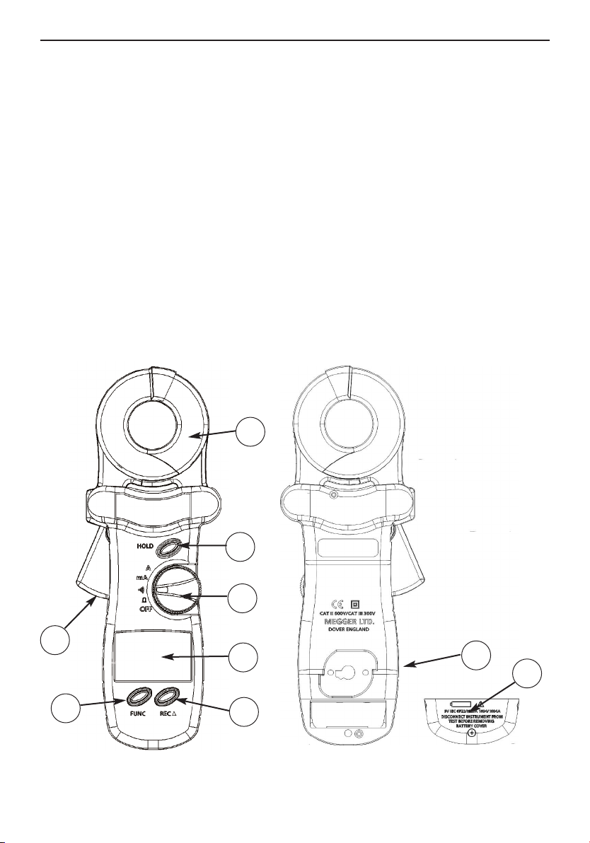
1. Jaws Assembly:
Encircle electrode or ground rod. No air gap is allowed between the two jaw halves.
2. Hold Button:
Maintains last measurement on display
3. Rotary Switch:
Power on and function selection.
4. LCD panel
s"button:
5. "REC
Function dependant on mode. Starts either data logging, single measurement recording, or data
download to PC. Also used to increment a value in conjunction with FUNC button.
6. FUNC button:
Press to select "HI" (high alarm), "LO" (low alarm), "SEC" (recording interval), "dL" (Data down
load), "no" (Read Data) or "232" (RS-232C)
7. Jaws opening lever
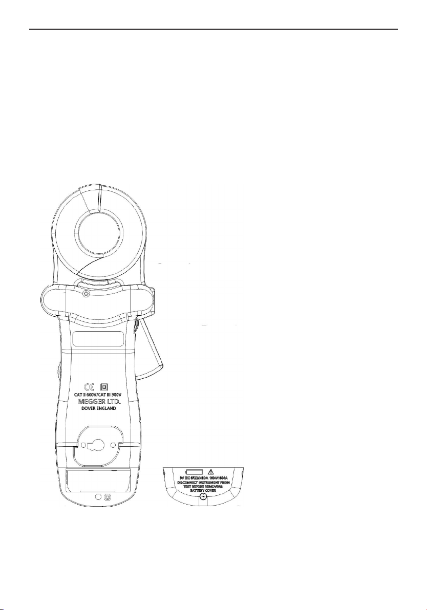
8. Battery cover
9. RS-232C interface connection point (DET20C only)
1
2
3
7
4
9
8
6
5
4
Page 6
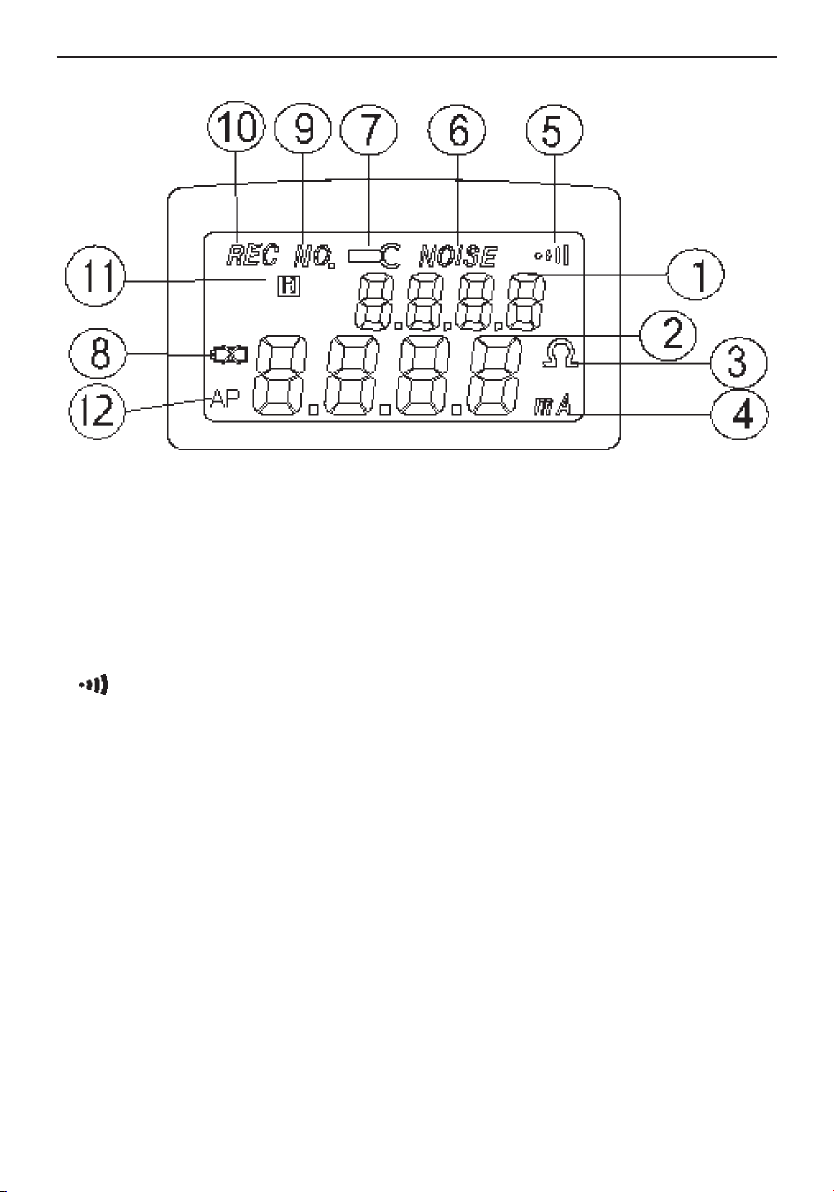
LIQUID CRYSTAL DISPLAY
1. Function Display current selected function or current record number.
2. Digits Display value from 0 to 9999 with decimal point.
3. Ohm Indicates resistance mode and alarm functions.
4. mA Indicates ground leakage current mode in mA or A
5. Indicates instrument is set at the alarm position.
6. NOISE: Indicates ground resistance tester senses noise or excessive
current present in the ground electrode
7. Jaw Open Displayed if the jaws are opened during the measurement,
this symbol and word OPEN will be shown in LCD.
8. Low Battery Indicates battery voltage is lower than required.
9. NO. Indicates the data record number in memory.
10. REC Indicates data logging is in progress.
11. H Indicates "HOLD" function activated
12. AP Indicates Auto Power Off activated. Deactivate by holding
down the REC button then turning on unit.
5
Page 7

OPERATING INSTRUCTIONS
Ground Resistance Measurement
1. Open the jaws and make sure that the mating surfaces are clean and free of dust, dirt or any
foreign substance.
2. Snap the jaws a few times to ensure clean contact is made.
3. Turn the rotary switch to the Ω position to power the instrument on. Do not clamp on to any
conductor or open the jaws, as this is a self-calibration phase.
4. At power on in _ mode, the instrument will perform a self-calibration for optimum accuracy. Users
must wait for self-calibration to be complete before use. During the self-calibration phase, the
LCD will show CAL7, CAL6, CAL5, CAL4, CAL 3, CAL2, and CAL1.
5. When the ground tester is ready, a beep will be heard.
6. Place the clamp around the electrode or ground rod to be measured. Operate the jaws a few
times for better accuracy.
7. Read the value of Rg (ground resistance) from LCD.
NOTE: For better measurement:
1. Operate the jaws a few times before powering on to clear mating surfaces.
2. Do not clamp on to any conductor during power up (point 3 above).
3. Operate the jaws a few times after clamping around the ground electrode.
NOTE: If self-calibration does not complete (The instrument will continue the process until a successful
self-calibration is achieved):
1. Check the jaw mating surfaces. If there is any dirt, dust, or any foreign substance, clean the surfaces.
2. Ensure the jaws are not open during self-calibration.
NOTE: Noise present in the electrode or ground rod.
If there is excessive current or over 30V noise in the ground rod, a symbol of "NOISE" will be shown in
LCD. Under these conditions, the reading is no longer accurate. We recommend the current flow is
measured before a resistance reading is taken.
NOTE: If jaws are opened during a measurement, a symbol of "OPEN" will be displayed on the LCD.
High and Low Alarm ( )
1. Set the rotary switch to the position.
2. Press the FUNC button to select "HI" or "LO" alarm. The present value of High or Low alarm will
be shown in the lower row of the LCD.
3. Press the
accelerates. The value can be set from 0 ohm to 1550 ohm and then OL. The value will roll over to
1(HI) or 0 (LO) if the set value in incremented past OL.
4. Once the value is set, press the FUNC button several times until the upper row LCD does not show
any letters.
s button to increment the value by 1 ohm. If the button is held down, the rate of increment
6
Page 8
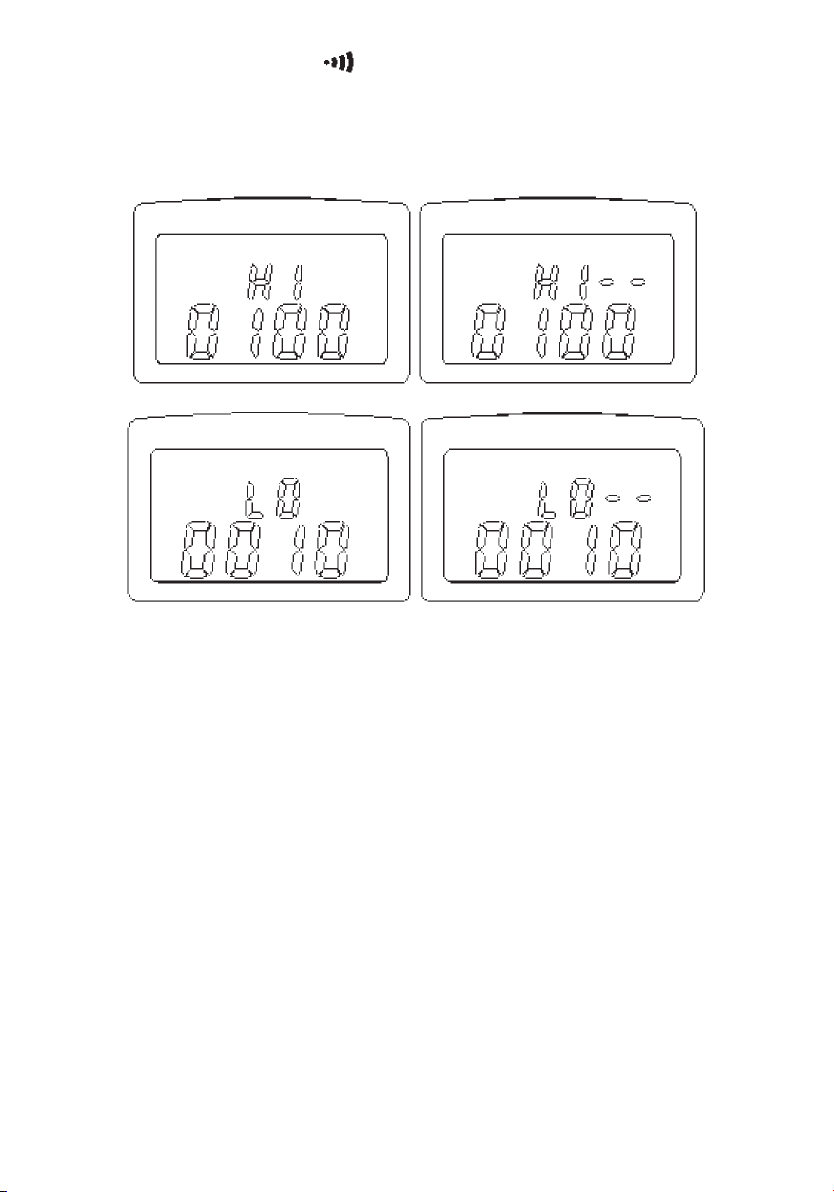
5. When the rotary switch is set at the position the instrument will compare the measured value
with the high and low values. If the measurement is higher than the HI value, the unit will beep
and show "HI --" in the upper row of LCD. If the current measurement is lower than the LO value, the
unit will beep and show "LO-- " in the upper row of LCD.
NOTE: If the HI value is set at OL, or the LO value is set at 0, the ALARM function is disabled. The
HI or LO value can be disabled individually
NOTE: The HI value cannot be lower than the LO value. Similarly the LO value cannot be higher than
the HI value. HI value will be adjusted to LO value plus 1 if roll-over occurs. The maximum value of LO
value is HI value minus 1.
NOTE: If data logging is in progress, the beeper will be disabled to save battery power. However, the
LCD displays the warning letters of "HI—" or "LO—" if an alarm condition occurs
NOTE: The values for the high and low alarm are stored in the memory. The values will be active when
the unit is powered on and alarm mode selected.
Ground/Leakage Current Measurement
1. Set the rotary switch to the mA or A position.
2. Place the clamp around the electrode or ground rod to be measured.
3. Read the value of leakage cur
Setting the Sampling Interval
1. Press the FUNC button until the letters "SEC" are shown on the upper row of LCD.
7
rent displayed on the LCD.
Page 9

2. The unit shows the current sampling interval in seconds.
3. Press the
increment accelerates. The value can be set from 0 to 255 seconds. The set value will roll over to 0
when the maximum value of 255 seconds is reached.
4. Press the FUNC button several times until the upper row LCD does not show any symbols.
NOTE: The sampling interval is used for data logging and RS-232C output timing.
Data Logging
The unit will start data logging if the "REC s" button is pressed, and the symbol "REC" will be shown on
the LCD. Data will be recorded at the specified sampling interval. Data logging will be stopped if the
memory is full, or the unit detects a low battery condition, or the "REC s" button is pressed again.
NOTE: With sampling time greater than zero the Auto Power Off feature is disabled in this mode
NOTE: If the sampling interval is set at 0 seconds, one set of data is recorded. To record the next set of
data, press the "REC
approximately 1 second.
s button to increment the value by 1 second. If the button is held down, the rate of
s" button again. The record number and "REC" symbol is displayed for
Downloading Data to a PC (ASCII format)(DET20C only)
1. Connect the RS-232C cable to the unit and a PC.
2. Run any application software which can accept ASCII data.
3. Press the FUNC button until the symbol "dL" is shown in the upper row on the LCD. The number of
records in the memory is shown in the lower row on the LCD.
4. Press the "REC
next to the symbol "dL" when data is transferring to PC in ASCII format.
5. The process of down loading can only be halted by turning the instrument off.
6. To exit this function, press the FUNC button several times until the upper row LCD shows no symbols.
NOTE: The unit first sends the sampling time, then the rest of the data stored in memory is sent to the
PC.
s" button to down load all the data stored in the memory. The symbol " -- " is shown
8
Page 10

Format of Down Loaded Data (DET20C only)
The data is down loaded to the PC in ASCII format. In addition to data readings information includes
status of jaws open, noise, HI alarm, LO alarm, and low battery. Below is a list of abbreviations for each
ondition and an example of data down loaded to the PC:
c
List of abbreviations:
Abbreviation Abbreviation Abbreviation
OPEN Jaws open NS Noise HI Hi alarm
LO Low alarm HD Data Hold LB Battery low
Example of down loaded data:
0001 (sampling time)
10.00 ohm
10.02 ohm
5.200 ohm LO
1.000 ohm NS
1.500 mA
9.00 A
NOTE: Each record is ended by <CR> and <LF>. The corresponding ASCII codes for <CR> and
<LF> are 13 and 10.
Reading the Data Stored in Memory
This function allows users to read the data stored directly from the instrument display.
1. Press the FUNC button until the symbol "NO." is shown on the LCD. The current record number is
shown on the upper row of the LCD, the data is shown in the lower row of LCD.
2. Press the
3. Holding down the
when the last record is reached.
9
s button to read the next data record.
s button accelerates the rate of increment. The record number will roll over to 1
Page 11

Clearing the Data Memory
With the instrument powered down press and hold the FUNC button, then turn the power on. The
symbol "CL" will be shown to indicate that memory is cleared.
Enabling the RS-232C output (DET20C only)
To save battery power, the default condition is RS-232C output disabled. To output data to a PC
continuously, the RS232C can be enabled by the following procedure.
1. Press the FUNC button until the symbol " 232" is shown on the upper row of LCD.
2. If the RS-232C output is enabled, the symbol "-" will follow the symbol "232". Press the s button to
toggle the status of RS-232C output.
3. To exit this function, press the FUNC button several times until the upper row on the LCD is blank.
NOTE: The RS-232C output interval is also specified by the sampling interval. If the sampling interval is
set at 0 seconds, data is outputted every 0.5 seconds.
NOTE: The RS-232C output is automatically disabled if "data logging" is in progress.
Installation of Megger Download Manager Software (DET20C)
The DET20C instrument is supplied as standard with Megger Download Manager on CD
1. Hardware and Software Requirements: The requirements are detailed on the rear of the sleeve
containing the CD
2. Installation of the Program: Insert the CD. If the CD does not auto-run when inserted in the drive,
click on START, RUN, select your CD drive and run START.EXE from the CD. Follow the instructions to
install the program to PC.
Description of Megger Download Manager
The Megger Download Manager is a 32-bit Microsoft Windows™ application, which controls data transfer
from your DET20C instrument using a specific driver. The driver may be installed from the CD or from
our website www.megger.com. Download Manager receives data from the instrument and stores it in
comma separated format files that can be viewed and edited with the free C
included.
SV Viewer programme
10
Page 12

Megger Download Manager features:
1. Single step data download from the DET20C in CSV format
2. Files managed using standard Windows™ format
3. Powerful CSV Viewer included to view, sort, edit, graph and print downloaded data.
4. Compact driver files for quick and easy disk and internet updates
5. Full help facility
NOTE: For operation of the Megger Download Manager refer to the help menu included in the software.
NOTE: Selecting the DET20C driver, then clicking the "Download" button on the tool bar gives the
procedure for data download from the instrument
11
Page 13

PRINCIPLE OF OPERATION
Below is a simplified typical ground distribution system. The equivalent circuit is shown in Figure A. If
R1, R2, R3, ... Rnare simplified to Req, then only Rgand Reqare left in the circuit (refer to Figure B). If a
constant voltage is applied to the circuit, the following equation is true.
V=Rg+ R
Where
eq
Req= 1
Σ1
(
and R1, R2, ... Rnare similar values, and n is a large number (such as 200), then Reqwill be much less
If R
g
than Rgand approaches zero.
)
Ri i = 1, 2, ......, n
Example:
and R1, R2, ... Rnare all 10 Ω, respectively and n = 200. Then Reqby calculation equals
If R
g
Rg>> Req(Req 0)
R
eq= 1 = 0.05Ω
1
1
+
+ ... +
1
10 10 10
= Rg+ Req=10 + 0.05 =10.05 Ω a R
V
In this example, we can see that as long as the number of multiple electrodes is large enough, the
equivalent resistance is negligible with respect to the ground resistance to be measured.
a
12
Page 14

R
g
R
1
R
2
R3.....R
n
Figure A
R
1
R
R
3
2
.....R
n
l l l l l l
R
g
Figure B
R
eq
13
Page 15

ELECTRICAL SPECIFICATION
Ground Resistance (Auto range):
Range
2
Resolution Accuracy of Reading
1
0.025 - 0.250 Ω 0.002 Ω ±1.5% ±0.05 Ω
0.250 - 9.999 Ω 0.02 Ω ±1.5% ±0.1 Ω
10.00 - 99.99 Ω 0.04 Ω ±2.0% ±0.3 Ω
100.0 - 199.9 Ω 0.4 Ω ±3.0% ±1.0 Ω
200.0 - 400.0 Ω 2 Ω ±5.0% ±5 Ω
400.0 - 600.0 Ω 5 Ω ±10% ±10 Ω
600.0 - 1550 Ω 20 Ω ±20%
1. Loop resistance non-inductive, external field <50 A/m, external electrical field <1 V/m, conductor
centered in jaws.
2. Resistance Measurement Frequency: 3.333 KHz
High and Low Alarm
Range Resolution
High Alarm 0 - 1550 Ω1 Ω
Lo Alarm 0 - 1550 Ω1 Ω
Ground/Leakage Current
(Auto range, 50/60 Hz, True RMS, Crest Factor <3.5)
Range Resolution Accuracy of Reading
0.200 - 1.000 mA 0.001 mA ±2.0% ±0.05 mA
1.00 - 10.00 mA 0.01 mA ±2.0% ±0.03 mA
10.0 - 100.0 mA 0.1 mA ±2.0% ±0.3 mA
100 - 1000 mA 1 mA ±2.0% ±3 mA
Ground/Leakage Current (50/60 Hz, True RMS, Crest Factor < 3.5)
Range Resolution Accuracy of Reading
0.20 – 35.00 A 0.01 A ±2.0% ±0.03 A
Accuracy of Resistance Calibration Plate: ±
1%
Data Logging Capacity: 8180 records (DET20C), 116 records (DET10C)
Data Logging Interval: 1 to 255 seconds
RS-232C Output: 0.5 and 1 to 255 seconds
14
Page 16

GENERAL SPECIFICATIONS
Conductor Size: 35 mm (1.36") Ø approx.
Battery Type: 9V IEC 6 LR61 (Alkaline)
Display Type: 4 digits 9999 counts LCD
Range Selection: Auto
Overload Indication: OL
Power Consumption: 40 mA
Low Battery Indication:
Battery Life:
3000 measurements
B
Auto Power Down:5 minutes approx.
Sampling Time: 0.5 seconds
Operating Temperature:
0ºC to 50ºC (14ºF to 122ºF)
Operating Humidity: Less than 85% RH
Storage Temperature:
-20ºC to 60ºC (-4ºF to 122ºF)
Storage Humidity: Less than 75% RH
EMC 61326-1
Operational uncertainties: Refer to
www.megger.com
ACCESSORIES
Resistance Calibration Plate x 1
9V Battery (Installed) x 1
Users Manual x 1
Carrying Box x 1
Accessories (DET-20C)
RS-232C Cable
Megger Download Manager CD
Dimensions
276 mm (L) x 100 mm (W) x 47 mm (H)
10.8" (L) x 3.9" (W) x 1.9" (H)
Weight
750g/1.65lbs
15
Page 17
BATTERY REPLACEMENT
When the "low battery" symbol is displayed on the LCD, replace the old battery with a new battery.
emove instrument from test piece during battery change.
R
1. Turn the switch to the OFF position.
2. Unfasten the battery cover screw.
3. Lift and remove the battery cover.
4. Remove the old battery.
5. Install the new 9 V battery.
6. Replace the battery cover and secure the screw.
16
Page 18

REPAIR AND WARRANTY
The instrument circuit contains static sensitive devices, and care must be taken in handling the printed
ircuit board. If the protection of an instrument has been impaired it should not be used, and be sent
c
for repair by suitably trained and qualified personnel. The protection is likely to be impaired if, for
example, the instrument shows visible damage, fails to perform the intended measurements, has been
subjected to prolonged storage under unfavourable conditions, or has been exposed to severe transport
stresses.
New Instruments are Guaranteed for 1 Year from the Date of Purchase by the User.
Note
: Any unauthorized prior repair or adjustment will automatically invalidate the Warranty.
Instrument Repair and Spare Parts
For service requirements for Megger Instruments contact
Megger Limited or Megger
Archcliffe Road Valley Forge Corporate Center
Dover 2621 Van Buren Avenue
Kent CT17 9EN Norristown
England PA 19403 U.S.A.
Tel: +44 (0)1304 502243 Tel: +1 (610) 676-8579
Fax: +44 (0)1304 207342 Fax: +1 (610) 676-8625
Returning an Instrument for Repair
If returning an instrument to the manufacturer for repair, it should be sent, freight pre-paid, to the
appropriate address. A copy of the Invoice and of the packing note should be sent simultaneously by
airmail to expedite clearance through Customs. A repair estimate showing freight return and other
charges will be submitted to the sender, if required, before work on the instrument commences.
17
Page 19

M
DET10C/DET20C
PINCE DE CONTRÔLE DE TERRE
NOTICE D’UTILISATION
18
Page 20

G AVERTISSEMENT
n
Par mesure de sécurité, il est recommandé de porter des gants de caoutchouc, même si les
équipements sont correctement utilisés et mis à la terre.
n
La sécurité reste de la responsabilité de l’opérateur.
n
Prendre toutes les précautions nécessaires lors de l’utilisation de l’appareil à proximité d’équipements
sous tension.
n
Ne pas utiliser la pince de contrôle pour plier ou arracher l’électrode ou le fil de terre de
l’équipement testé.
n
Tous les objets métalliques ou fils connectés au circuit électrique devront être considérés comme
potentiellement dangereux jusqu’à la fin du test. Il en est de même pour le circuit de mise à la terre.
Définition des symboles utilisés
F Attention : risques de chocs électriques
G Attention : consulter les documents fournis avec l’appareil
t Double isolation
c IEC 61010-2-032 CAT III 300V, CAT II 600 V Degré de pollution 2
19
Page 21

TABLE DES MATIÈRES
AVERTISSEMENT 19
GÉNÉRALITÉS 21
DESCRIPTION DES CONTRÔLLES 22
AFFICHAGE À CRISTAUX LIQUIDES 23
UTILISATION 24
Mesure de la résistance de terre 24
Alarme haute et alarme basse ( ) 24
Mesure du courant de fuite 26
Réglage de l'intervalle d’échantillonnage 26
Saisie des données 26
Téléchargement des données vers un PC (format ASCII) (DET20C uniquement) 27
Format des données téléchargées (DET20C uniquement) 27
Lecture des données stockées en mémoire 28
Effacement des données en mémoire 28
Activation du transfert RS-232C (DET20C uniquement) 28
Installation du gestionnaire de téléchargement Megger (DET20C) 29
Description du gestionnaire de téléchargement Megger 29
PRINCIPE DE FONCTIONNEMENT 30
CARACTERISTIQUES ÉLECTRIQUES 32
CARACTERISTIQUES GÉNÉRALES 33
ACCESSORIES 33
REMPLACEMENT DE LA PILE 34
RÉPARATION ET GARANTIE 35
20
Page 22

GÉNÉRALITÉS
Grâce à cette pince de contrôle, l’utilisateur peut mesurer la résistance d’un piquet de mise à la terre
sans utiliser des piquets supplémentaires. Cet appareil est utilisé dans des circuits avec mises à la terre
multiples, sans qu’il soit besoin de déconnecter la terre à tester.
21
Page 23
DESCRIPTION DES CONTRÔLLES
1. Mâchoires : électrode formant un cercle fermé. Il n’existe aucun entrefer entre les deux moitiés des
mâchoires.
2. Touche « Hold »(maintient) : garde la dernière mesure affichée à l’écran.
3. Sélecteur rotatif : allume l’appareil et permet de sélectionner les différentes fonctions.
4. Affichage à cristaux liquides.
5. Touche « REC
saisie des données, soit l’enregistrement d’une seule mesure, soit le téléchargement des données vers
un PC. Elle permet également d’incrémenter une valeur quand elle est utilisée avec la touche « FUNC
» (fonction).
6. Touche « FUNC » (fonction) : appuyer sur cette touche pour sélectionner « HI » (alarme haute), « LO »
(alarme basse), « SEC » (intervalle entre deux enregistrements), « dL » (téléchargement des données),
« NO » (lecture des données) ou « 232 » (RS-232C).
7. Levier d’ouverture des mâchoires.
8. Couvercle du logement de pile
9. Point de connexion RS-232C (DET20C uniquement).
s » (enregistrement) : cette fonction dépend du mode choisi. Elle déclenche, soit la
1
2
3
7
4
9
8
6
5
22
Page 24

AFFICHAGE À CRISTAUX LIQUIDES
1. Fonction : Affiche la fonction sélectionnée ou le numéro de l’enregistrement en cours.
2. Chiffres : Affiche une valeur comprise entre 0 et 9999 avec un point décimal.
3. Ohm : Indique que l’appareil est réglé en mode de mesure de résistance. Indique les
alarmes.
4. mA : Indique que l’appareil est réglé en mode de mesure du courant de fuite en mA
ou A.
5. : Indique que l’appareil est réglé en position d’alarme.
6. NOISE : (Perturbations). Indique que la pince de contrôle détecte des perturbations ou un
courant excessif dans l’électrode de terre.
7. Mâchoires
ouvertes : Indique si les mâchoires sont ouvertes lors de la mesure. Ce symbole, ainsi
que le mot « OPEN » (ouvert), s’affichent sur l’écran.
8. Pile faible : Indique que le niveau de charge de la pile est inférieur à celui requis.
9. NO : (numéro). Indique le numéro d’enregistrement des données.
10. REC : (enregistrement). Indique que la saisie des données est en cours.
11. H : Indique que la fonction « HOLD » (maintient) est activée.
12. AP : Indique que la mise à l’arrêt automatique est activée. Pour désactiver cette
fonction, maintenir la touche « REC
l’appareil.
s » (enregistrement) pressée et allumer
23
Page 25

UTILISATION
Mesure de la résistance de terre
1. Ouvrir les mâchoires et s’assurer que les surfaces de contact sont propres et exemptes de poussière,
salissures ou corps étrangers.
2. Faire fonctionner les mâchoires plusieurs fois pour s’assurer que le contact s’établit correctement.
3. Tourner le sélecteur sur la position « Ω » pour allumer l’appareil. L’appareil exécute alors un autoétalonnage. Ne pas positionner la pince sur un conducteur et ne pas ouvrir les mâchoires pendant
cette étape.
4. Quand l’appareil est allumé en mode « _ », il effectue un auto-étalonnage qui garantit une précision
optimale. L’utilisateur
cette étape, l’écran affiche le compte à rebours : CAL7, CAL6, CAL5, CAL4, CAL3, CAL2 et CAL1.
5. Quand l’appareil est prêt, il émet un signal sonore.
6. Positionner la pince autour de l’électrode ou du piquet de mise à la terre à mesurer. Faire
fonctionner les mâchoires plusieurs fois pour garantir la meilleure précision possible.
7. La valeur de Rg (résistance de terre) s’affiche sur l’écran à cristaux liquides.
Nota : Pour obtenir une mesure optimale
1. Faire fonctionner les mâchoires plusieurs fois avant d’allumer l’appareil pour nettoyer les surfaces de
contact.
2. Ne pas positionner la pince sur un conducteur lors de la phase de démarrage (point 3 ci-dessus).
3. Faire fonctionner les mâchoires plusieurs fois après avoir positionné la pince autour de l’électrode de
mise à la terre.
doit attendre la fin de cet auto-étalonnage avant d’utiliser l’appareil. Lors de
Nota : Si l’auto-étalonnage ne se termine pas (l’appareil continue la procédure jusqu’à ce que l’autoétalonnage soit terminé avec succès) :
1. Vérifier les surfaces de contact des mâchoires. En présence de poussière, salissures ou corps
étrangers, nettoyer les surfaces.
2. Vérifier que les mâchoires sont bien fermées lors de l’auto-étalonnage.
Nota : En présence de perturbations dans l’électrode ou le piquet de mise à la terre.
En présence d’un courant excessif ou en cas de perturbation supérieure à 30 V dans le piquet de mise à
la terre, le message « NOISE » (perturbations) s’affiche à l’écran. Dans ces conditions, l’exactitude de la
valeur indiquée n’est plus assurée. Nous recommandons de mesurer le flux de courant avant d’exécuter
la mesure de la résistance.
Nota : Si les mâchoires sont ouvertes pendant la mesure, le message « OPEN » (ouvert) s’affiche à
l’écran.
Alarme haute et alarme basse ( )
1. Positionner le sélecteur rotatif sur
2. Appuyer sur la touche « FUNC » (fonction) pour sélectionner « HI » (alar
basse). La valeur courante de l’alarme s’affiche sur la ligne inférieure de l’écran.
3. Appuyer sur la touche «
le taux d’incrémentation s’accélère. La valeur est réglable entre 0 ohm et 1 550 ohms,
s » pour incrémenter la valeur de 1 ohm. Si la touche est maintenue pressée,
.
me haute) ou « LO » (alarme
24
Page 26

passé cette valeur, « OL » (dépassement) s’affiche. Si le réglage dépasse « OL », la valeur repasse à 1 pour
l’alarme haute ou à 0 pour l’alarme basse.
4. Une fois la valeur réglée, appuyer sur la touche « FUNC » (fonction) à plusieurs reprises jusqu’à ce que
la ligne supérieure de l’écran n’affiche plus aucun message.
5. Quand le sélecteur rotatif est positionné sur « », l’appareil compare la valeur mesurée aux valeurs
des alarmes haute et basse. Si la valeur mesurée est supérieure à la valeur haute, l’appareil émet un
signal sonore et indique « HI -- » sur la ligne supérieure de l’écran. Si la valeur mesurée est inférieure à
la valeur basse, l’appareil émet un signal sonore et indique « LO-- »" sur la ligne supérieure de l’écran.
NOTA: : Si la valeur haute est réglée à « OL » ou si la valeur basse est réglée à 0, l’alarme est désactivée.
Les valeurs haute et basse peuvent être désactivées individuellement.
NOTA: : La valeur haute ne peut être inférieure à la valeur basse. De même, la valeur basse ne peut être
supérieure à la valeur haute, en cas de réglage erroné, la valeur haute sera ajustée à la valeur basse plus
1. La valeur basse maximale est égale à la valeur haute moins 1.
NOTA: Le signal sonore est désactivé pendant la saisie des données pour économiser la pile. Cependant,
en situation d’alarme, l’écran affichera les messages d’avertissement « HI-- » ou « LO-- ».
NOTA: Les valeurs de l’alarme haute et de l’alarme basse sont mémorisées. Ces valeurs sont actives dès
que l’appareil est allumé et que le mode alarme est sélectionné.
25
Page 27

Mesure du courant de fuite
1. Positionner le sélecteur rotatif sur « mA » ou « A ».
2. Positionner la pince autour de l’électrode ou du piquet de mise à la terre à mesurer.
3. La valeur du courant de fuite s’affiche sur l’écran à cristaux liquides.
Réglage de l’intervalle d’échantillonnage
1. Appuyer sur la touche « FUNC » (fonction) jusqu’à ce que le message « SEC » s’affiche sur la ligne
supérieure de l’écran.
2. L’appareil indique l’intervalle d’échantillonnage courant en secondes.
3. Appuyer sur la touche
pressée, le taux d’incrémentation s’accélère. La valeur est réglable entre 0 et 255 secondes. La valeur
repasse à 0 dès que la valeur maximale de 255 secondes est atteinte.
4. Appuyer sur la touche « FUNC » (fonction) à plusieurs reprises jusqu’à ce que la ligne supérieure de
l’écran n’affiche plus aucun message.
s pour incrémenter la valeur de 1 seconde. Si la touche est maintenue
NOTA: L’intervalle d’échantillonnage est utilisé lors de la saisie des données et de la synchronisation du
transfert RS-232C.
Saisie des données
L’appareil démarre la saisie des données dès que l’utilisateur appuie sur la touche « REC s »
(enregistrement). Le message « REC » s’affiche sur l’écran à cristaux liquides. Les données sont
enregistrées selon l’intervalle d’échantillonnage spécifié. La saisie des données s’arrête si la mémoire est
saturée, si l’appareil détecte une charge de la pile insuffisante ou si l’utilisateur appuie de nouveau sur la
touche « REC s ».
NOTA: Si la durée d’échantillonnage est supérieure à zéro, l’arrêt automatique est désactivé dans ce
mode.
NOTA: Si l’intervalle d’échantillonnage est réglé à 0 seconde, l’appareil enregistre un ensemble de
données. Pour enregistrer l’ensemble de données suivant, appuyer de nouveau sur la touche « REC
Le numéro de l’enregistrement et le message « REC » sont affichés pendant environ 1 seconde.
s ».
26
Page 28

Téléchargement des données vers un PC (format ASCII) (DET20C uniquement)
1. Connecter l’appareil et le PC à l’aide du câble RS-232C.
2. Démarrer un logiciel pouvant prendre en charge le format ASCII.
3. Appuyer sur la touche « FUNC » (fonction) jusqu’à ce que le message « dL » (téléchargement) s’affiche
sur la ligne supérieure de l’écran à cristaux liquides. Le nombre d’enregistrements stockés dans la
mémoire s’affiche sur la ligne inférieure de l’écran.
4. Appuyer sur la touche «
message « -- » s’affiche à côté des lettres « dL » lors du téléchargement des données vers le PC au
format ASCII.
5. Il n’est possible d’arrêter le téléchargement des données qu’en éteignant l’appareil.
6. Pour sortir de cette fonction, appuyer sur la touche « FUNC » (fonction) à plusieurs reprises jusqu’à ce
que la ligne supérieure de l’écran n’affiche plus aucun message.
NOTA: : L’appareil envoie en premier la durée d’échantillonnage, puis les autres données stockées dans
la mémoire sont téléchargées vers le PC..
Format des données téléchargées (DET20C uniquement)
Les données sont téléchargées vers un PC au format ASCII. En plus des données, les informations
transmises incluent les avertissements en cas de mâchoires ouvertes, de perturbations, d’alarme haute,
d’alarme basse et de pile faible. Le tableau ci-dessous donne la liste des abréviations correspondant à
chaque cas ainsi qu’un exemple de données téléchargées vers un PC :
Liste des abréviations
OPEN Mâchoires ouvertes NS Perturbations HI Alarme haute
LO Alarme basse HD Données en attente LB Pile faible
s" » pour transférer toutes les données stockées dans la mémoire. Le
Exemple de données téléchargées :
0001 (durée d’échantillonnage)
10.00 ohm
10.02 ohm
5.200 ohm LO
1.000 ohm NS
1.500 mA
9.00 A
NOTA: Chaque enregistrement se ter
et <LF> sont respectivement 13 et 10.
27
mine par <CR> et <LF>. Les codes AS
respondant à <CR>
CII cor
Page 29

Lecture des données stockées en mémoire
Cette fonction permet à l’utilisateur de lire les données stockées directement sur l’écran de l’appareil.
1. Appuyer sur la touche « FUNC » (fonction) jusqu’à ce que le message « NO » (numéro) s’affiche sur
l’écran à cristaux liquides. Le numéro de l’enregistrement en cours s’affiche sur la ligne supérieure de
l’écran, les données s’affichent sur la ligne inférieure de l’écran.
2. Appuyer sur la touche «
3. Pour accélérer le défilement des enregistrements, maintenir la touche «
enregistrement est atteint, le numéro repasse à 1.
Effacement des données en mémoire
L’appareil étant éteint, maintenir la touche « FUNC » (fonction) pressée puis allumer l’appareil. Le
message « CL » (effacement) s’affiche pour indiquer que la mémoire a été effacée.
s » pour lire l’enregistrement suivant.
s » pressée. Quand le dernier
Désactivé Activé
Activation du transfert RS-232C (DET20C uniquement)
Pour économiser la pile, le transfert RS-232C est désactivé par défaut. Pour télécharger des données en
continu vers un PC, le transfert RS-232C peut être activé selon la procédure suivante :
1. Appuyer sur la touche « FUNC » (fonction) jusqu’à ce que le chiffre « 232 » s’affiche sur la ligne
supérieure de l’écran.
2. Si le transfert RS-232C est activé, le symbole « - » s’affiche à la suite de « 232 ». Appuyer sur la touche «
s » pour modifier l’état du transfert RS-232C.
3. Pour sortir de cette fonction, appuyer sur la touche « FUNC » (fonction) à plusieurs reprises jusqu’à ce
que la ligne supérieure de l’écran n’affiche plus aucun message.
NOTA: La cadence du transfert RS-232C est également spécifiée par l’intervalle d’échantillonnage. Si
l’intervalle d’échantillonnage est réglé à 0 seconde, les données sont transférées toutes les 0,5 secondes.
NOTA : Le transfert RS-232C est automatiquement désactivé si une saisie de données est en cours.
28
Page 30

Installation du gestionnaire de téléchargement Megger (DET20C)
L’appareil DET20C est fourni en standard avec le logiciel de téléchargement Megger enregistré sur CD.
1. Spécifications minimales matérielles et logicielles : ces informations se trouvent à l’arrière du boîtier
contenant le CD.
2. Installation du programme : Insérer le CD dans le lecteur. Si l’installation ne démarre pas
automatiquement, cliquer sur « Démarrer », puis sur « Exécuter », rechercher le lecteur de CD et
démarrer l’application « START.EXE » à partir du CD. Suivre les instructions pour installer le
programme sur le PC.
Description du gestionnaire de téléchargement Megger
1) Le téléchargement en une étape des données du DET20C au format CSV.
2) La gestion des fichiers sous Windows™.
3) La visualisation, le tri, le traçage, l’édition et l’impression des données téléchargées grâce au logiciel
CSV Viewer.
Il offre :
4) Des pilotes compacts, rapidement et facilement mis à jour, soit à partir du CD, soit via Internet.
5) Une aide complète.
NOTA: La notice d’utilisation du gestionnaire de téléchargement Megger s’obtient via le menu « aide »
compris dans le logiciel.
NOTA: Pour télécharger les données à partir de l’appareil, sélectionner le lecteur DET20C et cliquer sur
le bouton « Download » (téléchargement) de la barre d’outils.
29
Page 31

PRINCIPE DE FONCTIONNEMENT
Le schéma ci-après représente un circuit de mise à la terre simplifié. Le circuit équivalent est illustré
Figure A. Si R1, R2, R3, ... Rnsont ramenées à une résistance équivalente Req, le circuit ne comporte plus
que Rget Req(Réf. Figure B). Si une tension constante est appliquée sur le circuit, l’équation suivante est
vérifiée :
R
V
Où:
+ R
g
=
eq
Req= 1
Σ1
(
)
Ri i = 1, 2, ......, n
Si Rg et R
largement inférieure à Rget tend vers zéro.
Exemple:
Si Rg et R
, R2, ... Rnsont de même valeur et si n est un nombre élevé (par exemple 200), alors Reqest
1
Rg>> Req(Req 0)
, R2, ... Rnsont toutes égales à 10 Ω et si n = 200. Alors, par calcul, Reqest égal à :
1
Req= 1 = 0.05Ω
1
1
+
+ ... +
1
10 10 10
V = Rg+ Req=10 + 0.05 =10.05Ω a R
Cet exemple montre que, si le nombre d’électrodes est suffisamment élevé, la résistance équivalente est
négligeable par rapport à la résistance de terre à mesurer.
a
30
Page 32

R
g
R
1
R
2
R3.....R
n
Figure A
R
1
R
R
3
2
.....R
n
l l l l l l
R
g
Figure B
R
eq
31
Page 33

CARACTERISTIQUES ÉLECTRIQUES
Résistance de terre (choix de la plage automatique) :
Plage de mesure2 Résolution Précision de la mesure1
0.025 - 0.250 Ω 0.002 Ω ±1.5% ±0.05 Ω
0.250 - 9.999 Ω 0.02 Ω ±1.5% ±0.1 Ω
10.00 - 99.99 Ω 0.04 Ω ±2.0% ±0.3 Ω
100.0 - 199.9 Ω 0.4 Ω ±3.0% ±1.0 Ω
200.0 - 400.0 Ω 2 Ω ±5.0% ±5 Ω
400.0 - 600.0 Ω 5 Ω ±10% ±10 Ω
600.0 - 1550 Ω 20 Ω ±20%
1 Résistance de boucle non-inductive, champ externe < 50 A/m, champ électrique externe < 1 V/m,
conducteur centré dans les mâchoires.
2 Fréquence de la mesure de la résistance : 3.333 KHz
Alarme haute et alarme basse
Plage Résolution
Alarme haute 0 - 1550 Ω1 Ω
Alarme basse 0 - 1550 Ω 1 Ω
Courant de fuite
(50/60 Hz, RMS vrai, facteur de crête < 3,5)
Plage de mesure Résolution Précision de la mesure
0.200 - 1.000 mA 0.001 mA ±2.0% ±0.05 mA
1.00 - 10.00 mA 0.01 mA ±2.0% ±0.03 mA
10.0 - 100.0 mA 0.1 mA ±2.0% ±0.3 mA
100 - 1000 mA 1 mA ±2.0% ±3 mA
Courant de fuite (50/60 Hz, RMS vrai, facteur de crête < 3,5)
Plage de mesure Résolution Précision de la mesure
0.20 – 35.00 A 0.01 A ±2.0% ±0.03 A
Précision de la plaque d’étalonnage de la résistance: ±1 %
Capacité de saisie des données : 8 180 enregistrements (DET20C), 116 enregistrements (DET10C).
Intervalle de saisie des données : 1 à 255 secondes.
Transfert RS-232C : 0,5 et 1 à 255 secondes.
32
Page 34

CARACTERISTIQUES GÉNÉRALES
ACCESSOIRES
Taille du conducteur:
Ø 35 mm (1,36") environ
Type de pile: 9 V CEI 6 LR61 (alcaline)
Display Type: A cristaux liquides, 4 chiffres 9999
Sélection de la plage de mesure: Automatique
Indication de dépassement: OL
Power Consumption: 40 mA
Consommation : 40mA
Indication de pile faible :
Durée de vie de la pile:
B
3 000 mesures
Arrêt automatique: au bout de 5 minutes
environ
Durée d’échantillonnage: 0.5 secondes
Domaine de fonctionnement:
Température:”0ºC à 50ºC (14ºF à 122ºF)
Humidité: Inférieure à 85 % HR
Domaine de stockage:
Température: ”-20ºC à +60ºC (-4ºF à +122ºF)
Humidité: Inférieure à 75% HR
EMC 61326-1
Incertitudes opérationnelles: visite
www.megger.com
Dimensions
276 mm (L) x 100 mm (W) x 47 mm (H)
10.8" (L) x 3.9" (W) x 1.9" (H)
Poids
750g/1.65lbs
1 Plaque d’étalonnage
1 Pile 9 V (posée)
1 Notice d’utilisation
1 Boîtier de transport
Accessoires (DET-20C)
Câble RS-232C
CD avec gestionnaire de téléchargement Megger
33
Page 35

REMPLACEMENT DE LA PILE
ès que le signal « low battery » (pile faible) s’affiche sur l’écran, remplacer la pile par une neuve. Lors
D
du remplacement de la pile, retirer l’appareil du circuit testé.
1. Tourner le sélecteur sur la position « OFF ».
2. Dévisser la vis maintenant le couvercle.
3. Soulever et déposer le couvercle.
4. Retirer la pile usagée.
5. Insérer une nouvelle pile de 9 V.
6. Reposer le couvercle et serrer la vis.
34
Page 36

Réparation et Garantie
Les circuits de l’instrument contiennent des éléments sensibles à l’electricite statique et il y a lieu de
prendre des précautions en manipulant la carte de circuits imprimes. Si la protection d’un instrument
s’est trouvee affectée de quelque maniére il ne doit pas être utilisé et doit être expeedié pour réparation
par du personnel convenablement formé et qualifié. La protection de l’appareil peut s’être trouvée
endommagée si par exemple l’instrument apparaît visiblement abîmee, ne donne pas les performances
attendues, s’est trouvé entreposé de façon prolongée dans des conditions défavorables ou a été exposé
a des contraintes extrêmes durant son transport.
LES NOUVEAUX INSTRUMENTS SONT GARANTIS PENDANT UNE PÉRIODE D’UN AN À
PARTIR DE LA DATE DE LEUR ACHAT PAR L’UTILISATEUR.
Note: Le fait d’ouvrir le boîtier annule automatique-ment la garantie couvrant l’instrument à moins que
l’opération ne soit faite par un organisme de réparation agréé.
Réparation d’instruments et pièces de rechange
For service requirements for Megger Instruments contact
Megger Limited ou Megger
Archcliffe Road Z.A. Du Buisson de la Couldre
Dover 23 rue Eugène Henaff
Kent CT17 9EN 8190 TRAPPES
England France
Tel: +44 (0)1304 502243 Tel: +33 (1) 30.16.08.90
Fax: +44 (0)1304 207342 Fax: +33 (1) 34.61.23.77
Renvoi D’un Instrument Pour le faire Réparer
Si un instrument est réexpédiê au fabricant pour être reparé il doit être envoyé port payé a l’adresse
appropriée. Un exemplaire de la facture et la note d’envoi doivent être envoyé par avion au même
moment afin de hâter les formalités de douane. Un devis estimé des réparations indiquant les frais de
réexpedition et autres frais sera si nécessaire adressé a l’expéditeur avant que les opérations de
réparation ne soient enterprises.
35
Page 37

DET10C/DET20C
ERDUNGSPRÜFZANGE
M
BEDIENUNGSANLEITUNG
36
Page 38

G WARNHINWEIS
n
Aus Sicherheitsgründen sollten auch dann Gummihandschuhe getragen werden, wenn die Anlage
sachgemäß betrieben wird und ordnungsgemäß geerdet ist.
n
Das Bedienpersonal ist für die Sicherheit verantwortlich.
n
Gehen Sie mit äußerster Vorsicht vor, wenn Sie das Gerät an stromführenden elektrischen Anlagen
benutzen.
n
Versuchen Sie nicht, das Erdungsprüfgerät dazu zu verwenden, die Erdelektrode oder den Erdleiter
von der zu erdenden Anlage wegzudrehen oder zu –biegen.
n
Bis eine Prüfung das Gegenteil gezeigt hat, muss angenommen werden, dass alle Metallgegenstände
oder Drähte, die an dem elektrischen System angeschlossen sind, lebensgefährlich sind. Dazu gehört
auch das Erdungssystem.
Definition der Symbole:
F Vorsicht: Risiko eines elektrischen Schlags
G Vorsicht: Siehe Begleitdokumente
t Doppelte Isolierung
c IEC 61010-2-032 CAT III 300V, CAT II 600V Verschmutzungsgrad 2
37
Page 39

INHALTSVERZEICHNIS
WARNHINWEIS 37
BESCHREIBUNG DER FUNKTIONEN 39
BESCHREIBUNG DER BEDIENELEMENTE 40
FLÜSSIGKRISTALLANZEIGE 41
BEDIENUNGSANLEITUNG 42
Bodenwiderstandsmessung 42
Alarm bei hohen und niedrigen Messwerten ( ) 43
Erd-/Kriechstrommessung 44
Das Abtastintervall einstellen 44
Datensammlung 44
Herunterladen von Daten auf einen PC (ASCII-Format) (nur DET20C) 44
Format der heruntergeladenen Datei (nur DET20C) 45
Lesen der im Speicher abgelegten Daten 45
Löschen des Datenspeichers 46
Einrichten der RS-232C-Ausgabe (nur DET20C) 46
Installation der Megger Download Manager Software (DET20C) 46
Beschreibung des Megger Download Managers 47
FUNKTIONSWEISE 48
ELEKTRISCHE DATEN 50
ALLGEMEINE ANGABEN 51
ZUBEHÖR 51
ERNEUERN DER BATTERIE 52
REPARATUREN UND GARANTIE 53
38
Page 40

BESCHREIBUNG DER FUNKTIONEN
Das Erdungsprüfgerät zum Anklemmen erlaubt dem Benutzer, den Bodenwiderstand einer Erdelektrode
ohne Einsatz von Hilfserdelektroden zu messen. Das Erdungsprüfzange kann an mehrfach geerdeten
Systemen eingesetzt werden, ohne dass die zu untersuchende Erdung abgetrennt werden muss.
39
Page 41

BESCHREIBUNG DER BEDIENELEMENTE
. Zangenbaugruppe: Zum Umschließen von Elektrode oder Erdstab. Zwischen den beiden
1
Zangenhälften darf sich kein Luftspalt befinden.
2. Halte-Taste: Die Anzeige der letzten Messung bleibt auf dem Display bestehen
3. Drehschalter: Netzschalter und Funktionsauswahl.
4. LCD-Anzeige
s"-Taste: Modusabhängige Funktion. Leitet entweder die Datensammlung, Aufzeichnung
5. „REC
einzelner Messungen oder das Herunterladen von Daten auf einen PC ein. Wird auch zusammen mit
der FUNC-Taste dazu verwendet, einen Wert zu erhöhen.
6. „FUNC"-Taste: Durch Drücken dieser Taste können „HI" (Alarm bei hohem Messwert), „LO" (Alarm bei
niedrigem Messwert), „SEC" (Aufnahmeintervall), „dL" (Herunterladen von Daten), „No" (Daten
einlesen) oder „232" (RS-232C) ausgewählt werden.
7. Zangen-Öffnungshebel
8. Batterieabdeckung
9. RS-232C-Schnittstellen-Anschlusspunkt (nur DET20C)
1
2
3
7
4
9
8
6
5
40
Page 42

FLÜSSIGKRISTALLANZEIGE
1. Funktion Anzeige der aktuell ausgewählten Funktion oder der aktuellen Datensatznummer
2. Stellen Zeigt Werte zwischen 0 und 9999 mit Dezimalpunkt an
3. Ohm Zeigt den Widerstandsmodus und die Alarmfunktionen an.
4. mA Zeigt den Erdkriechstrommodus in mA oder A an.
5. Zeigt an, dass das Gerät auf die Alarmposition eingestellt ist.
6. NOISE (RAUSCHEN):
Zeigt an, dass das Erdungsprüfgerät Rauschen oder übermäßigen Strom in der
Erdelektrode misst.
7. Zangen offen Wird angezeigt, wenn die Zangen sich während der Messung öffnen. Dieses
Symbol und das Wort „Open" (Offen) werden auf der LCD angezeigt.
8. Niedriger Batterieladezustand
Zeigt an, dass die Batteriespannung unterhalb des erforderlichen Werts liegt.
9. NO. Zeigt die Datensatznummer im Speicher an.
10. REC Zeigt an, dass die Datensammlung erfolgt.
11. H Zeigt an, dass die „HOLD"-F
12. AP Zeigt an, dass die automatische Abschaltung aktivier
der REC-Taste und anschließendes Einschalten des Geräts deaktiviert.
unktion (HAL
TEN) aktivier
t ist.
t ist. W
ird durch F
esthalten
41
Page 43

BEDIENUNGSANLEITUNG
Bodenwiderstandsmessung
1. Öffnen Sie die Zangen und achten Sie darauf, dass die Passflächen sauber und frei von Staub, Schmutz
oder Fremdkörpern sind.
2. Lassen Sie die Zangen einige Male einschnappen, um zu gewährleisten, dass ein Kontaktschluss
vorliegt.
3. Stellen Sie den Drehschalter auf die W-Position, um das Gerät einzuschalten.
Gerät zu diesem Zeitpunkt nicht an einen Leiter und öffnen Sie auch nicht die Zangen, da
es sich um einen Selbstkalibrierungsvorgang handelt.
4. Beim Einschalten im _-Modus führt das Gerät eine Selbstkalibrierung zur optimalen Genauigkeit
durch. Die Benutzer müssen vor dem Gebrauch des Geräts den Abschluss der Selbstkalibrierung
abwarten. Während der Selbstkalibrierungsphase zeigt die LCD CAL7, CAL6, CAL5, CAL4, CAL 3, CAL2
und CAL1 an.
5. Wenn das Erdungsprüfgerät betriebsbereit ist, ertönt ein Piepton.
6. Legen Sie die Zangen um die zu messende Elektrode oder den Erdstab. Betätigen Sie die Zangen
einige Male, um eine höhere Genauigkeit zu erhalten.
7. Lesen Sie den Rg–Wert von der LCD ab.
Hinweis: Für genauere Messungen:
1. Betätigen Sie die Zangen einige Male, bevor Sie sie an saubere Passflächen anschließen.
2. Klemmen Sie das Gerät während der Einschaltphase nicht an einen Leiter an (siehe Punkt 3 oben).
3. Betätigen Sie die Zangen nach dem Anklemmen um die Erdelektrode einige Male.
Klemmen Sie das
Hinweis: Wenn die Selbstkalibrierung nicht abgeschlossen wird (Das Gerät fährt mit dem Prozess fort,
bis eine zufriedenstellende Selbstkalibrierung erreicht ist):
1. Prüfen Sie die Passflächen der Zangen. Wenn sie Schmutz, Staub oder Fremdkörper aufweisen,
müssen sie gereinigt werden.
2. Sorgen Sie dafür, dass die Zangen während der Selbstkalibrierung nicht offen stehen.
HINWEIS: In der Elektrode oder im Erdstab liegt Rauschen vor.
Wenn ein übermäßiger Strom oder ein Rauschen von über 30V in der Erdelektrode vorliegen, wird das
„NOISE"-Symbol (RAUSCHEN) auf der LCD angezeigt. Unter diesen Umständen ist der Messwert nicht
mehr genau. Wir empfehlen, dass der Stromfluss gemessen wird, bevor eine Widerstandsmessung
durchgeführt wird.
Hinweis: Wenn die Zangen während einer Messung offen stehen, erscheint das „OPEN"-Symbol (OFFEN)
auf der LCD.
42
Page 44

Alarm bei hohen und niedrigen Messwerten ( )
1. Den Drehschalter auf die Position stellen
2. Die FUNC-Taste drücken, um „HI"- oder „LO"-Alarm auszuwählen. Der aktuelle Wert für den hohen
oder niedrigen Alarmwert wird in der unteren Zeile der LCD angezeigt.
3. Die °∂-Taste drücken, um den Wert um 1 Ohm zu erhöhen. Wenn die Taste festgehalten wird, erhöht
sich der Wert schneller. Der Wert kann zwischen 0 Ohm und 1500 Ohm und dann auf OL eingestellt
werden. Der Wert stellt sich auf 1(HI) oder 0 (LO) zurück, wenn der eingestellte Wert über OL hinaus
erhöht wird.
4. Sobald der Wert eingestellt worden ist, die FUNC-Taste mehrmals drücken, bis die obere Zeile der
LCD keine Buchstaben mehr anzeigt.
5. Wenn der Drehschalter auf die Position eingestellt wird, vergleicht das Gerät den gemessenen
Wert mit den Werten für den hohen und niedrigen Alarm. Wenn eine Messung über dem HI-Wert liegt,
lässt das Gerät einen Piepton ertönen und zeigt in der oberen Zeile der LCD „HI--" an. Wenn die
aktuelle Messung unter dem LO-Wert liegt, lässt das Gerät einen Piepton ertönen und zeigt in der
oberen Zeile der LCD „LO--" an
HINWEIS: Wenn der HI-Wert auf OL und der LO-Wert auf 0 eingestellt sind, ist die Alarmfunktion
deaktiviert. Der HI- oder LO-Wert können individuell deaktiviert werden.
HINWEIS: Der HI-Wert darf nicht kleiner als der LO-Wert sein. Gleichermaßen darf der LO-Wert nicht
größer als der HI-Wert sein. Der HI-Wert wird auf den LO-Wert plus 1 angepasst, wenn eine
Zurückstellung erfolgt. Der maximale Wert für den LO-Wert ist gleich dem HI-Wert minus 1.
HINWEIS: Wenn die Datensammlung vor sich geht, wird der Piepton deaktiviert, um Batterieleistung zu
sparen. Die LCD zeigt jedoch die Warnsymbole „HI—" oder „LO—" an, wenn ein Alarmzustand auftritt.
HINWEIS: Die Werte für den hohen und den niedrigen Alarm werden im Speicher abgelegt. Die Werte
43
Page 45

werden aktiviert, wenn das Gerät eingeschaltet und der Alarmmodus gewählt wird.
Erd-/Kriechstrommessung
1. Den Drehschalter auf die Position mA oder A stellen
2. Die Zangen um die zu messende Elektrode oder den Erdstab legen.
3. Den Messwert für den Kriechstrom ablesen, der auf der LCD angezeigt wird.
Das Abtastintervall einstellen
1. Die FUNC-Taste drücken, bis die Buchstaben „SEC" in der oberen Zeile der LCD erscheinen.
2. Das Gerät zeigt das aktuelle Abtastintervall in Sekunden an.
3. Die s-Taste drücken, um den Wert um 1 Sekunde zu erhöhen. Wenn die Taste festgehalten wird,
erhöht sich der Wert schneller. Der Wert kann zwischen 0 und 255 Sekunden eingestellt werden. Der
eingestellte Wert stellt sich auf Null zurück, wenn der Maximalwert von 255 Sekunden erreicht ist.
4. Die FUNC-Taste mehrmals drücken, bis die obere Zeile der LCD keine Symbole mehr zeigt.
HINWEIS: Das Abtastintervall wird zur Datensammlung und zum RS-232C-Ausgabe-Timing verwendet.
Datensammlung
Das Gerät beginnt mit der Datensammlung, wenn die „REC s"-Taste gedrückt wird und das Symbol
„REC" erscheint auf der LCD. Die Daten werden mit dem eingegebenen Abtastintervall aufgezeichnet.
Die Datensammlung wird unterbrochen, wenn der Speicher voll ist, oder das Gerät einen niedrigen
Batterieladezustand erfasst, oder die „REC s"-Taste erneut gedrückt wird.
HINWEIS: Bei Abtastraten, die größer als Null sind, ist die Funktion der automatischen Abschaltung in
diesem Modus deaktiviert.
HINWEIS: Wenn das Abtastintervall auf 0 Sekunden eingestellt ist, wird ein Datensatz aufgezeichnet. Um
den nächsten Datensatz aufzuzeichnen, muss die „REC
Datensatznummer und das „REC"-Symbol werden ungefähr 1 Sekunde lang angezeigt.
Herunterladen von Daten auf einen PC (ASCII-Format) (nur DET20C)
1. Das RS-232C-Kabel an das Gerät und einen PC anschließen.
2. Die Applikationssoftware aufrufen, die ASCII-Daten empfangen kann.
3. Die FUNC-Taste drücken, bis das Symbol „dL" in der oberen Zeile der LCD erscheint. Die Anzahl der
Datensätze im Speicher wird in der unteren Zeile der LCD angezeigt.
4. Die „REC
wird neben dem Symbol „dL" angezeigt, wenn die Daten in AS
werden.
s"-Taste drücken, um alle im Speicher abgelegten Daten herunterzuladen. Das Symbol „—"
s"-Taste erneut gedrückt werden. Die
ormat auf den PC übertragen
CII-F
44
Page 46

5. Der Vorgang des Herunterladens kann durch Ausschalten des Geräts unterbrochen werden.
6. Um diese Funktion zu verlassen, drücken Sie die FUNC-Taste mehrmals, bis in der oberen Zeile der
LCD keine Symbole mehr erscheinen.
HINWEIS: Das Gerät überträgt zuerst die Abtastzeit. Anschließend werden die restlichen im Speicher
abgelegten Daten an den PC gesendet
Format der heruntergeladenen Datei (nur DET20C)
Die Daten werden auf den PC in ASCII-Format heruntergeladen. Zusätzlich zu den Daten enthalten die
Messwertinformationen den Angaben über den Zustand der Zangen, Rauschen, HI-Alarm, LO-Alarm und
niedrige Batterieladung. Weiter unten sind eine Liste der Abkürzungen für jeden Zustand und ein
Beispielsatz für die auf den PC heruntergeladenen Daten abgebildet:
Liste der Abkürzungen:
Abkürzung Abkürzung Abkürzung
OPEN Zangen offen NS Rauschen HI Alarm für hohen Wert
LO Alarm für niedrigen Wert HD Daten halten LB Niedriger
Batterieladezustand
Beispiel für einen heruntergeladenen Datensatz:
0001 (Abtastrate)
10.00 Ohm
10.02 Ohm
5.200 Ohm LO
1.000 Ohm NS
1.500 mA
9.00 A
HINWEIS: Jeder Datensatz endet mit <CR> (Wagenrücklauf) und <LF> (Zeilenvorschub). Die
entsprechenden ASCII-Codes für <CR> und <LF> sind 13 und 10.
Lesen der im Speicher abgelegten Daten
Diese Funktion ermöglicht den Benutzern, abgelegte Daten direkt von der Gerätanzeige abzulesen.
1. Die FUNC-Taste drücken, bis das Symbol „NO." Auf der LCS erscheint. Die aktuelle Datensatznummer
wird in der oberen Zeile der LCD angezeigt, die Daten werden in der unteren Zeile der LCD
dargestellt.
2. Drücken Sie die
3. Festhalten der
wenn der letzte Datensatz erreicht ist.
45
s-Taste, um den nächsten Datensatz zu lesen.
s-Taste beschleunigt die Anzeigerate. Die Datensatznummer wird auf 1 zurückgestellt,
Page 47

Löschen des Datenspeichers
Bei ausgeschaltetem Gerät die FUNC-Taste drücken und festhalten, anschließend das Gerät einschalten.
Das Symbol „CL" erscheint um anzuzeigen, dass der Speicher gelöscht wurde.
Einrichten der RS-232C-Ausgabe (nur DET20C)
Um Batterieleistung einzusparen, ist die RS-232C-Ausgabe als Standardeinstellung deaktiviert. Um
kontinuierlich Daten an einen PC auszugeben, kann die RS232C-Schnittstelle mit Hilfe des folgenden
Vorgangs aktiviert werden.
1. Die FUNC-Taste drücken, bis die Buchstaben „232" in der oberen Zeile der LCD erscheinen.
2. Wenn die RS-232C-Ausgabe aktiviert ist, folgt dem Symbol „232" das Symbol „—". Drücken Sie die s-
Taste, um den Status der RS-232C-Ausgabe umzuschalten.
3. Um diese Funktion zu verlassen, drücken Sie die FUNC-Taste mehrmals, bis in der oberen Zeile der
LCD keine Symbole mehr erscheinen.
(Deaktiviert)
HINWEIS: Das RS-232C-Ausgabeintervall wird ebenfalls durch das Abtastintervall definiert. Wenn das
Abtastintervall auf 0 Sekunden eingestellt ist, wird alle 0,5 Sekunden ein Datensatz ausgegeben.
HINWEIS: Die RS-232C-Ausgabe wird automatisch deaktiviert, wenn eine Datensammlung vor sich geht.
Installation der Megger Download Manager Software (DET20C)
Das DET20C-Gerät wird in der Standardausführung mit dem Megger Download Manager auf CD
geliefert.
1. Hardware- und Software-Anforderungen: Die auf der Rückseite der CD-Hülle angegebenen
Anforderungen.
2. Installation des Programms
CD einlegen. Wenn die CD nicht automatisch anläuft, nachdem sie in das Laufwerk eingelegt worden
ist, auf START, dann auf RUN klicken, das CD-Laufwerk auswählen und START.EXE von der CD
aufrufen. Die Anweisungen für die Installation des Programms auf dem PC befolgen.
(Aktiviert)
46
Page 48

Beschreibung des Megger Download Managers
Der Megger Download Manager ist eine 32-Bit-Microsoft Windows™-Applikation, die den Datentransfer
von Ihrem DET20C-Gerät mit Hilfe eines bestimmten Treibers steuert. Der Treiber kann von der CD
oder von unserer Website www.megger.com installiert werden. Download Manager empfängt Daten von
dem Gerät und speichert sie in Formatdateien mit Kommata als Trennzeichen, die mit der beigefügten
kostenlosen Software CSV Viewer angezeigt und editiert werden können.
Eigenschaften des Megger Download Managers
1. Daten-Download in einem Schritt von dem DET20C-Gerät im CSV-Format
2. Dateien werden mit Hilfe des Standard Windows™-Format verwaltet
3. Leistungsstarker CSV Viewer zur Ansicht, Bearbeitung, grafischen Darstellung und zum Ausdruck der
heruntergeladenen Daten beigefügt
4. Kompakte Treiberdateien für schnelle und leichte Updates von Disk oder aus dem Internet
5. Vollständige Hilfe-Funktion
HINWEIS: Hinweise zur Bedienung des Megger Download Managers finden Sie im Hilfemenü der
Software.
HINWEIS: Durch Auswählen des DET20C-Treibers und Klicken auf die Download-Taste in der
Werkzeugleiste können Sie den Vorgang zum Herunterladen von Daten von dem Gerät einsehen.
47
Page 49

FUNKTIONSWEISE
Unten ist ein vereinfachtes typisches Bodenverteilungssystem abgebildet. Der zugehörige Schaltkreis ist
n Abbildung A dargestellt. Wenn R
i
R
im Schaltkreis über (siehe Abbildung B). Wenn an den Schaltkreis eine konstante Spannung
eq
angelegt wird, gilt die folgende Gleichung.
V=Rg+ R
R
R
... R
u R
,
,
,
1
2
3
n
eq
ereinfacht werden, bleiben nur noch R
z
v
eq
nd
u
g
wobei
Req= 1
Σ1
(
Wenn R
ist Reqviel kleiner als Rgund geht gegen Null.
Beispiel:
Wenn R
den Wert
und R1, R2, ... Rn ähnliche Werte haben und n eine große Zahl bezeichnet (wie z.B. 200), dann
g
Rg>> Req(Req 0)
und R1, R2, ... Rn alle jeweils 10 Ω, betragen und n = 200 ist, hat Reqder Berechnung zufolge
g
R
eq= 1 = 0.05Ω
)
Ri i = 1, 2, ......, n
1
1
+
+ ... +
1
10 10 10
V
= Rg+ Req=10 + 0.05 =10.05 Ω a R
Bei diesem Beispiel sehen wir, dass, solange die Anzahl der mehrfachen Elektroden groß genug ist, der
entsprechende Widerstand bezüglich des zu messenden Bodenwiderstands vernachlässigbar ist.
a
48
Page 50

R
g
R
1
R
2
R3.....R
n
49
Figure A
R
1
R
R
3
2
.....R
n
l l l l l l
R
g
Figure B
R
eq
Page 51

ELEKTRISCHE DATEN
BODENWIDERSTAND (Automatischer Bereich):
Bereich
2
Auflösung Genauigkeit des Messwerts
1
0.025 - 0.250 Ω 0.002 Ω ±1.5% ±0.05 Ω
0.250 - 9.999 Ω 0.02 Ω ±1.5% ±0.1 Ω
10.00 - 99.99 Ω 0.04 Ω ±2.0% ±0.3 Ω
100.0 - 199.9 Ω 0.4 Ω ±3.0% ±1.0 Ω
200.0 - 400.0 Ω 2 Ω ±5.0% ±5 Ω
400.0 - 600.0 Ω 5 Ω ±10% ±10 Ω
600.0 - 1550 Ω 20 Ω ±20%
1. Schleifenwiderstand, nicht-induktives, externes Feld < 50 A/m, externes elektrisches Feld < 1 V/m,
Leiter in Klemmbacken zentriert.
2. Widerstandsmessungsfrequenz: 3.333 KHz
Alarm bei hohen und niedrigen Messwerten
Bereich Auflösung
Alarm bei hohem Messwert 0 - 1550 Ω 1 Ω
Alarm bei niedrigem Messwert 0 - 1550 Ω1 Ω
Erd-/Kriechstrom
(Automatischer Bereich, 50/60Hz, echter RMS, Spitzenfaktor < 3,5)
Bereich Auflösung Genauigkeit des Messwerts
0.200 - 1.000 mA 0.001 mA ±2.0% ±0.05 mA
1.00 - 10.00 mA 0.01 mA ±2.0% ±0.03 mA
10.0 - 100.0 mA 0.1 mA ±2.0% ±0.3 mA
100 - 1000 mA 1 mA ±2.0% ±3 mA
Erd-/Kriechstrom (50/60 Hz, echter RMS, Spitzenfaktor < 3,
Bereich Auflösung Genauigkeit des Messwerts
0.20 – 35.00 A 0.01 A ±2.0% ±0.03 A
Genauigkeit der Widerstandskalibrierungsplatte: ±1%
Datensammlungskapazität: 8180 Datensätze (DET20C), 116 Datensätze (DET10C)
Datensammlungsintervall: 1 bis 255 Sekunden
RS-232C-Ausgabe: 0,5 und 1 bis 255 Sek
unden
50
Page 52

ALLGEMEINE ANGABEN
Leitergröße: Ø ungefähr 35mm.
Batterietyp: 9V IEC 6 LR61 (Alkali-Batterie)
Displaytyp: LCD mit 4 Stellen, 9999 Zahlen
Bereichswahl: automatisch
Überlastanzeige: OL
Stromverbrauch: 40 mA
Anzeige für niedrige :
Batterielebensdauer:
B
3000 Messungen
Automatische Abschaltung: nach ungefähr 5
Minuten
Abtastzei: 0,5 Sekunden
Betriebstemperatu: 0ºC bis 50ºC
Betriebsluftfeuchtigkeit: unter 85% rel.
Feuchte
Lagertemperatu: -20ºC to 60ºC
Lagerluftfeuchtigkeit: unter 75% rel. Feuchte
EMC 61326-1
Betriebliche Unklarheiten:
Besuch www.megger.com
ZUBEHÖR
iderstandskalibrierungsplatte x 1
W
9V-Batterie (installiert) x 1
Benutzerhandbuch x 1
Tragekasten x 1
Zubehör (DET20C
RS-232C-Kabel
Megger Download Manager-CD
Abmessungen 276 mm (L) x 100 mm (W)
x 47 mm (H)
Gewicht 750g
51
Page 53

ERNEUERN DER BATTERIE
enn das Symbol „niedrige Batterieleistung" auf der LCD angezeigt wird, muss die alte Batterie durch
W
eine neue Batterie ersetzt werden. Entfernen Sie das Gerät während des Batteriewechsels von der zu
prüfenden Anlage.
1. Stellen Sie den Drehschalter auf die AUS-Position.
2. Montieren Sie die Schraube der Batterieabdeckung ab.
3. Heben Sie die Batterieabdeckung ab und legen Sie sie zur Seite.
4. Entnehmen Sie die alte Batterie.
5. Setzen Sie die neue 9V-Batterie ein.
6. Setzen Sie die Batterieabdeckung wieder auf und schrauben Sie sie fest.
52
Page 54

REPARATUREN UND GARANTIE
Das Instrument enthält statisch empfindliche Bauteile, weshalb die Leiterplatte sorgfältig behandelt
werden muß. Falls die Schutzvorrichtungen eines Instruments beschädigt worden sind, sollte es nicht
verwendet, sondern an eine geeignete Reparaturwerkstatt geschickt werden. Die Schutzvorrichtungen
sind wahrscheinlich beschädigt, wenn folgende Bedingungen vorliegen: sichtbare Beschädigung,
fehlende Anzeige der erwarteten Meßergebnisse; längere Lagerung unter widrigen Bedingungen oder
starke Transportbelastung.
NEUE INSTRUMENTE UNTERLIEGEN EINER GARANTIE VON 1 JAHR AB DEM DATUM DES
KAUFS DURCH DEN BENUTZER.
Hinweis: Das Gehäuse darf nur von entsprechend autorisierten Reparaturfirmen geöffnet werden, da
sonst die Garantie für dieses Instrument automatisch erlischt.
Reparaturarbeiten und Ersatzteile
Wenden Sie sich zwecks Wartungsarbeiten an Megger-lnstrumenten entweder an:
Megger Limited oder Megger
Archcliffe Road Valley Forge Corporate Center
Dover 2621 Van Buren Avenue
Kent, CT17 9EN. Norristown, PA 19403
England. U.S.A.
Tel: +44 (0) 1304 502243 Tel: +1 610 676-8579
Fax: +44 (0) 1304 207342 Fax: +1 610 676-8625
oder an eine autorisierte Reparaturfirma.
Einsenden Eines Instruments Zur Reparatur
Wenn ein Instrument zwecks Reparatur zurück-geschickt werden muß, sollte es mit vorbezahlter Fracht
an die angebrachte Anschrift gesandt werden. Gleichzeitig sollte zur Erledigung der britischen
Zollformalitäten per Luftpost eine Kopie der Rechnung zusammen mit dem Packzettel eingesandt
werden. Auf Wunsch wird dem Absender vor Ausführung irgendwelcher Arbeiten am Instrument ein
Kostenvoranschlag unter Berücksichtigung der Frachtkosten und anderer Gebühren zugesandt.
535455
Page 55

Page 56

Page 57

M
DET10C/DET20C
PROBADOR DE PINZA PARA LA
RESISTENCIA DE TIERRA
MANUAL DEL USUARIO
56
Page 58

G ADVERTENCIA
n
El uso de guantes de hules es una buena práctica de seguridad aunque el equipo esté correctamente
operado y puesto a tierra.
n
La seguridad es responsabilidad del operador.
n
Utilice las precauciones cuando use el instrumento alrededor de equipos eléctricos energizados.
n
No intente usar el probador para la resistencia de tierra para retorcer o palanquear el electrodo de
tierra o el conductor de tierra fuera del equipo que se está conectando a tierra.
n
Debe suponerse que todos los objetos metálicos o cables conectados a un sistema eléctrico son
letales hasta que no se los pruebe, y el sistema de puesta a tierra no es una excepción.
Definición de los símbolos:
F Precaución: Riesgo de choque eléctrica
G Precaución: Consulte los documentos adjuntos
t Doble aislamiento
c IEC 61010-2-032 CAT III 300V, CAT II 600V Grado 2 de contaminación
57
Page 59

TABLA DE CONTENIDOS
ADVERTENCIA 57
DESCRIPCIÓN DE LAS CARACTERÍSTICAS 59
DESCRIPCIÓN DE LAS FUNCIONES 60
PANTALLA DE CRISTAL LÍQUIDO 61
INSTRUCCIONES DE FUNCIONAMIENTO 62
Medición de la resistencia de tierra 62
Alarma alta y baja ( ) 62
Medición de la corriente de fuga a tierra 63
Ajuste del intervalo de muestreo 64
Registro de datos 64
Cargar de los datos a un PC (sólo DET20C) 64
Formato de los datos descargados (sólo DET20C) 65
Lectura de los datos guardados en la memoria 65
Borrar los datos de la memoria 66
Activación de la salida de RS-232C (sólo DET20C) 66
Instalación del software del Administrador de descarga de Megger (sólo DET20C) 66
Descripción del Administrador de descarga de Megger 67
OPERACIÓN PRINCIPAL 68
ESPECIFICACIÓN ELÉCTRICA 70
ESPECIFICACIONES GENERALES 71
ACCESORIOS 71
REEMPLAZO DE LA BATERÍA 72
REPARACIÓN Y GARANTÍA 73
58
Page 60

DESCRIPCIÓN DE LAS CARACTERÍSTICAS
El probador de pinza para la resistencia de tierra permite medir la resistencia de tierra de una varilla de
tierra sin usar varillas de tierra auxiliares. El probador de pinza para la resistencia de tierra se usa en
sistemas con varias puestas a tierra sin desconectar la puesta a tierra que se está probando.
59
Page 61

DESCRIPCIÓN DE LAS FUNCIONE
1. Montaje de la mandíbula: Ciña el electrodo o la varilla de tierra. No debe quedar ningún espacio
abierto entre ambas mitades de la mandíbula.
2. Botón "Hold" (Mantener): Mantiene la última medición en la pantalla..
3. Selector giratoria: Encender y selección de funciones.
4. Pantalla tipo "LCD"
5. Botón " REC
medición o la carga de datos a la computadora. Conjuntamente con el botón FUNC también se usa
para incrementar un valor.
6. Botón " FUNC": Púlselo para seleccionar "HI" (alarma alta), "LO" (alarma baja), "SEC" (intervalo de
registro), "dL" (carga de datos), "no" (lectura de datos) o "232" (RS-232C).
7. Palanca para abrir la pinza.
8. Tapa de la batería
9. Punto de conexión de la interfaz RS-232C (sólo DET20C)
s" La función depende del modo. Inicia la carga de datos, el registro de una sola
1
2
3
7
4
9
8
6
5
60
Page 62

PANTALLA DE CRISTAL LÍQUIDO
1. FunciónMuestra la función seleccionada o el número de registro actual.
2. Dígitos Muestra el valor desde 0 a 999, con punto decimal.
3. Ohmio Indica el modo resistencia y las funciones de alarma.
4. mA Indica el modo corriente de fuga a tierra en mA o A.
5. Indica que el instrumento está ajustado en la posición de alarma.
6. NOISE: Indica que el probador para la resistencia de tierra detecta la presencia de ruido
o corriente excesiva en el electrodo de tierra.
7. Pinza abierta Se muestra si la pinza se abre durante la medición. La pantalla mostrará este
símbolo y la palabra OPEN.
8. Batería baja Indica que el voltaje de la batería está por debajo de lo necesario.
9. NO. Indica el número del registro de los datos en la memoria.
10. REC Indica que la introducción de datos está en proceso.
11. H Indica que está activada la función "HOLD".
12. AP Indica que está habilitada la función de apagar automática. Se inhabilita por
mantener el botón REC oprimido y luego encender la unidad.
61
Page 63

INSTRUCCIONES DE FUNCIONAMIENTO
Medición de la resistencia de tierra
1. Abra la pinza y asegúrese de que ambas superficies de acoplamiento estén limpias y libres de polvillo,
suciedad o cualquier sustancia extraña.
2. Cierre la pinza varias veces para asegurarse de que ambos contactos cierren perfectamente.
3. Gire el selector giratorio a la posición W para encender el instrumento. No lo sujete a ningún
conductor ni abra la pinza, ya que esta es una fase de calibración automática.
4. Al encenderse en modo _, para obtener una precisión óptima el instrumento realizará una calibración
automática. Antes de usarlo, el usuario debe esperar a que la calibración automática concluya.
Durante la fase de calibración automática, la pantalla LCD mostrará CAL7, CAL6, CAL5, CAL4, CAL 3,
CAL2 y CAL1.
5. Una vez que el probador para la resistencia de tierra esté listo, se oirá un sonido.
6. Coloque la pinza alrededor del electrodo o varilla de tierra que debe medirse. Para mayor precisión,
abra y cierre la pinza varias veces.
7. Lea el valor de Rg (resistencia de tierra) en la pantalla LCD.
NOTA: Para obtener una mejor medición:
1. Antes de conectar el instrumento haga funcionar la pinza varias veces para asegurarse de que las
superficies de acoplamiento estén perfectamente limpias.
2. Durante la puesta en funcionamiento, no lo sujete a ningún conductor (refiérase al punto 3 anterior).
3. Haga funcionar la pinza varias veces después de sujetarla alrededor de un electrodo de tierra.
NOTA: Si la calibración automática no se completa( el instrumento continuará el proceso hasta que
establece una calibración):
1. Controle las superficies de acoplamiento de la pinza. Si hay alguna suciedad, polvillo o sustancia
extraña, limpie las superficies.
2. Asegúrese de que la mandíbula no esté abierta durante la calibración automática.
NOTA: Si durante una medición se abre la pinza, la pantalla LCD mostrará un símbolo de "OPEN".
Si existe corriente excesiva o ruido superior a 30V en la varilla de tierra, la pantalla LCD mostrará un
símbolo de "NOISE". Bajo tales condiciones, la lectura deja de tener precisión. Recomendamos leer el
flujo de corriente antes de tomar una lectura de la resistencia.
NOTE: If jaws are opened during a measurement, a symbol of "OPEN" will be displayed on the LCD.
Alarma alta y baja ( )
1. Coloque el selector giratorio en la posición .
. Pulse el botón "FUNC" para seleccionar la alarma alta, "HI", o baja, "LO". El valor actual de la alarma alta
o baja se mostrará en la parte inferior de la pantalla LCD.
3. Pulse el botón
relación de incremento. El valor puede ajustarse desde 0 a 1500 ohmios y luego OL. El valor pasará a 1
(HI) o 0 (LO) si el valor establecido se incrementa más allá de OL.
s para incrementar el valor en 1 ohmio. Si mantiene el botón pulsado se acelera la
62
Page 64

4. Una vez establecido el valor, pulse el botón FUNC varias veces hasta que la fila superior la pantalla
LCD no muestre ninguna letra.
5. Cuando el selector se coloca en la posición el instrumento comparará el valor medido con los
valores alto y bajo. Si la medición es superior al valor alto, el instrumento comenzará a emitir un
sonido y mostrará "HI- -" en la fila superior de la pantalla. Si la medición actual es inferior al valor bajo,
el instrumento comenzará a emitir un sonido y mostrará "LO- -" en la fila superior de la pantalla.
NOTA: Si el valor alto se establece en OL, o si el valor bajo se establece en 0, se desactiva la función de
alarma. El valor alto o bajo puede desactivarse individualmente.
NOTA: El valor alto no puede ser inferior al valor bajo. Del mismo modo, el valor bajo no puede ser
superior al valor alto. El valor alto se ajustará al valor bajo más 1 si el conteo llega hasta el final y vuelve a
comenzar. El valor máximo del valor bajo es el valor alto menos 1.
NOTA: Si se están cargando datos, se desactivará la emisión de sonido para ahorrar vida a la batería. Sin
embargo, la pantalla LCD muestra las letras "HI- -" o "LO- -" si se presenta una situación por la que
debería sonar la alarma.
NOTA: Los valores de la alarma alta y baja se guardan en la memoria. Los valores estarán activos cuando
se enciende el instrumento y se selecciona el modo de alarma.
Medición de corriente de fuga a tierra
1. Coloque el selector giratorio en la posición mA o A .
2. Coloque la pinza alrededor del electrodo o varilla de tierra que debe medirse.
3. Lea el valor de la corriente de fuga indicada en la pantalla
63
Page 65

Ajuste del intervalo de muestreo
1. Pulse el botón FUNC hasta que se muestren las letras "SEC" en la fila superior de la pantalla.
2. La pantalla muestra el intervalo actual de muestreo en segundos.
3. Pulse el botón
relación de incremento. El valor puede establecerse desde 0 a 255 segundos. El valor establecido
regresará a 0 cuando se llega al valor máximo de 255 segundos.
4. Pulse el botón FUNC varias veces hasta que la fila superior de la pantalla no muestre ningún símbolo.
NOTA: El intervalo de muestreo se usa para cargar datos y configurar el tiempo de salida del
RS-232C.
Registro de datos
La unidad comenzará a registra datos si está pulsado el botón "REC s" _", y la pantalla mostrará el
símbolo "REC". Los datos se registrarán al intervalo de muestreo especificado. Si la memoria está llena, o
si la unidad detecta que la batería está baja, o si vuelve a pulsarse el botón "REC s", se detendrá la
introducción de datos.
NOTA: Si el tiempo de muestreo es mayor de cero, la función de apagar automática se deshabilita en
este modo.
NOTA: Si el intervalo de muestreo se establece en 0 segundos, se registra un juego de datos. Para
registrar el siguiente conjunto de datos, vuelva a pulsar el botón "REC
símbolo "REC" se muestran durante alrededor de 1 segundo.
s para incrementar el valor en 1 segundo. Si mantiene el botón pulsado se acelera la
s". El número de registro y el
Cargar de los datos a un PC (formato ASCII) (sólo DET20C)
1. Conecte el cable RS-232C al instrumento y al PC.
2. Ejecute cualquier software de aplicación que pueda aceptar datos ASCII.
3. Pulse el botón FUNC hasta que se muestre el símbolo "dL" en la fila superior la pantalla. La fila inferior
la pantalla muestra la cantidad de registros de la memoria.
4. Pulse el botón "REC
transfiriendo datos a un PC en formato ASCII, se muestra el símbolo "- -" junto al símbolo "dL".
5. El proceso de carga sólo puede detenerse apagando el instrumento.
6. Para salir de esta función, pulse el botón FUNC varias veces hasta que la fila superior la pantalla no
muestre ningún símbolo.
NOTA: La unidad envía primero el tiempo de muestreo y luego el resto de los datos guardados en la
memoria se envían al PC.
s" para cargar todos los datos guardados en la memoria. Cuando se están
64
Page 66

Formato de los datos descargados (sólo DET20C)
Los datos se descargan al PC en formato ASCII. En adición de las lecturas de datos, la información
incluye el estado abierto de la pinza, el ruido, alarma HI, alarma LO y batería baja. La tabla a
ontinuación muestra una lista de abreviaturas para cada situación y un ejemplo de los datos cargados al
c
PC:
Lista de abreviaturas:
Abreviatura Abreviatura Abreviatura
OPEN Pinza Abierta NS Ruido HI Alarma alta
LO Alarma baja HD Mantener datos LB Batería baja
Ejemplo de datos cargados:
0001 (tiempo de muestreo)
10.00 ohmios
10.02 ohmios
5.200 ohmios LO
1.000 ohmio NS
1.500 mA
9.00 A
NOTA: Cada registro termina con <CR> y <LF>. Los códigos ASCII correspondientes de <CR> y
<LF> son 13 y 10.
Lectura de los datos guardados en la memoria
Esta función permite que el usuario lea los datos guardados directamente en la pantalla del instrumento.
1. Pulse el botón FUNC hasta que la pantalla muestre el símbolo "NO.". El número del registro actual se
muestra en la fila superior la pantalla. Los datos se muestran en la fila inferior la pantalla.
2. Pulse el botón s para leer el siguiente registro de datos.
3. Si mantiene pulsado el botón "
regresará a 1 cuando se llega al último registro.
65
s" se acelera la relación de los incrementos. El número de registro
Page 67

Borrar los datos de la memoria
Con el instrumento apagado, mantenga pulsado el botón FUNC y luego enciéndalo. Se mostrará el
símbolo "CL" para indicar que se borraron los datos de la memoria.
Activación de la salida de RS-232C (sólo DET20C)
Para ahorrar vida a la batería, la salida de RS-232C está desactivada (Disabled) de modo predeterminado.
Para descargar datos a un PC de modo continuo, el RS232C puede activarse (Enabled) del siguiente
modo:
1. Pulse el botón FUNC hasta que se muestre el símbolo "232" en la fila superior de la pantalla.
2. Si la salida de RS-232C está activada, el símbolo "-" seguirá al símbolo "232". Pulse el botón
pasar de un estado a otro de salida de RS-232C.
3. Para salir de esta función, pulse el botón FUNC varias veces hasta que la fila superior de la pantalla
quede en blanco.
s para
NOTA: El intervalo de la salida de RS-232C también está especificado por el intervalo de muestreo. Si el
intervalo de muestreo se establece en 0 segundos, los datos se descargan cada 0,5 segundos.
NOTA: La salida de RS-232C se desactiva automáticamente si "registro de datos" está en proceso.
Instalación del software del Administrador de descarga de Megger (DET20C)
El Administrador de Carga de Megger en CD se incluye con el instrumento DET20C.
1. Requerimientos de hardware y software: Los requerimientos están detallados en la parte posterior del
sobre que contiene el CD.
2. Instalación del programa
Inserte el CD. Si el CD no se ejecuta automáticamente al insertarlo en la unidad correspondiente,
haga clic en START, RUN, seleccione la unidad de CD y ejecute START.EXE desde el CD. Siga las
instrucciones para instalar el programa en el PC.
66
Page 68

Descripción del Administrador de descarga de Megger
El Administrador de carga de Megger es una aplicación de Microsoft Windows™ de 32 bits que controla
la transferencia de datos desde el DET20C mediante un controlador específico. El controlador puede
instalarse desde el CD o desde nuestro sitio Web www.megger.com. El Administrador de carga recibe los
datos desde el instrumento y los guarda en ficheros de formato separados por comas que pueden verse
y editarse con el programa gratuito CSV Viewer que se incluye.
Características del Administrador de Carga de Megger:
1. Carga en un solo paso desde el DET20C en formato CSV.
2. Administración de archivos mediante el formato estándar de Windows™.
3. Se incluye el poderoso CSV Viewer para ver, clasificar, editar, graficar e imprimir los datos cargados.
4. Archivos de controlador compactos para realizar actualizaciones rápidas y sencillas desde un disco e
Internet.
5. Función de ayuda.
NOTA: Para conocer el funcionamiento del Administrador de carga de Megger, consulte el menú de
ayuda incluido en el software.
NOTA: Al seleccionar el controlador de DET20C y luego hacer clic en el botón "Download" de la barra de
herramientas, puede cargar los datos desde el instrumento.
67
Page 69

OPERACIÓN PRINCIPAL
A continuación se muestra un típico sistema de distribución de tierra. El circuito equivalente se muestra
n la Figura A. Si R
e
(refiérase a la Figura B). Si se aplica un voltaje constante al circuito, la siguiente ecuación es verdadera:
R
R
... R
,
,
1
2
e simplifican a Req, entonces sólo R
,
s
3
n
R
uedan en el circuito
y
q
g
eq
V=Rg+ R
Donde
eq
Req= 1
Σ1
(
Si R
and R1, R2, ... Rnson valores similares, y n es un número grande (como 200), entonces ReqReq será
g
mucho menos que Rgy se acercará a cero.
Ejemplo
Si R
and R1, R2, ... Rnson todos 10 Ω, respectivamente y n = 200. Entonces Reqpor cálculo equivale a
g
Rg>> Req(Req 0)
eq= 1 = 0.05Ω
R
)
Ri i = 1, 2, ......, n
1
1
+
+ ... +
1
10 10 10
V
= Rg+ Req=10 + 0.05 =10.05 Ω a R
En este ejemplo podemos ver que mientras la cantidad de múltiples electrodos sea lo suficientemente
grande, la resistencia equivalente es insignificante con relación a la resistencia de tierra a ser medida.
a
68
Page 70

R
g
R
1
R
2
R3.....R
n
Figure A
R
1
R
R
3
2
.....R
n
l l l l l l
R
g
Figure B
R
eq
69
Page 71

ESPECIFICACIÓN ELÉCTRICA
Resistencia de tierra (rango automático)
Rango
2
Resolución Precisión de lectura
1
0.025 - 0.250 Ω 0.002 Ω ±1.5% ±0.05 Ω
0.250 - 9.999 Ω 0.02 Ω ±1.5% ±0.1 Ω
10.00 - 99.99 Ω 0.04 Ω ±2.0% ±0.3 Ω
100.0 - 199.9 Ω 0.4 Ω ±3.0% ±1.0 Ω
200.0 - 400.0 Ω 2 Ω ±5.0% ±5 Ω
400.0 - 600.0 Ω 5 Ω ±10% ±10 Ω
600.0 - 1550 Ω 20 Ω ±20%
1. Resistencia de bucle no inductiva, campo externo < 50 A/m, campo eléctrico externo < 1 V/m,
conductor centrado en la pinza.
2. Frecuencia de medición de la resistencia: 3.333 KHz
Alarma alta y baja
Rango Resolución
Alarma alta 0 - 1550 Ω 1 Ω
Alarma baja 0 - 1550 Ω1 Ω
Corriente de fuga a tierra
(Rango automático, 50/60 Hz, RMS verdadero, factor de amplitud < 3,5)
Rango Resolución Precisión de lectura
0.200 - 1.000 mA 0.001 mA ±2.0% ±0.05 mA
1.00 - 10.00 mA 0.01 mA ±2.0% ±0.03 mA
10.0 - 100.0 mA 0.1 mA ±2.0% ±0.3 mA
100 - 1000 mA 1 mA ±2.0% ±3 mA
Corriente de fuga a tierr (50/60 Hz, RMS reales, factor de amplitud < 3,5)
Rango Resolución Precisión de lectura
0.20 – 35.00 A 0.01 A ±2.0% ±0.03 A
Placa de calibración de la precisión de lectura: ±1%
Data Logging Capacity: 8180 registros (DET20C), 116 registros (DET10C
Capacidad de registro de datos: 1 to 255 seconds
Salida de RS-232C: 0,5 y 1 a 255 segundos
70
Page 72

ESPECIFICACIONES GENERALES
Tamaño del conductor: 35 mm (1.36") Ø
approx.
Tipo de batería: 9V IEC 6 LR61 (Alcalina)
Tipo de pantalla: Pantalla de cristal líquido
(LCD) con conteos de 4 dígitos hasta 9999
Selección de rango: Automática
Indicación de sobrecarga: OL
Consumo de potencia: 40 mA
Indicación de batería baja:
Vida útil de la batería:
B
3000 mediciones
Reducción automática de potencia: 5
minutos aprox.
Tiempo de muestreo: 0.5 segundos
Temperatura de funcionamiento:
0ºC a 50ºC (14ºF a 122ºF)
Humedad de funcionamiento: Menos de 85%
de HR
Temperatura de almacenamiento:-
-20ºC a 60ºC (-4ºF a 122ºF)
Humedad de almacenamiento: Menos de 75%
de HR
EMC 61326-1
Inexactitudes operacionales: visita
www.megger.com
ACCESORIOS
placa de calibración de la resistencia
1
1 batería de 9V (instalada)
1 Manual del usuario
1 caja para transportarlo
Accesorios (DET-20C)
Cable de RS-232C
CD del Administrador de descarga de Megger
Dimensiones
276mm (L) x 100mm (An.) x 47mm (Al.)
10,8" (L) x 3,9"(An.) x 1,9"(Al.)
Peso:
750g/1,65lbs
71
Page 73

REEMPLAZO DE LA BATERÍA
Cuando la pantalla muestra el símbolo de "batería baja", reemplace la batería usada por una nueva.
Mientras realiza el cambio, retire el instrumento de la pieza de prueba.
1. Coloque el interruptor en la posición OFF.
2. Remueve el tornillo de la tapa de la batería.
3. Levante y retire la tapa de la batería.
4. Remueve la batería gastada.
5. Instale la batería de 9V nueva.
6. Vuelva a colocar la tapa de la batería y ajuste el tornillo.
72
Page 74

REPARACIÓN Y GARANTÍA
El instrumento contiene dispositivos sensibles estáticos y se debe tener cuidado al manipular el panel de
circuito impreso. Si la protección de un instrumento se ve afectada, este no debe utilizarse: envíelo para
que sea reparado por personal adecuadamente entrenado y calificado. Probablemente la protección
resulte dañada si, por ejemplo, el instrumento presenta daño visible; no logra realizar las mediciones
deseadas; ha permanecido almacenado durante un período prolongado bajo condiciones desfavorables;
o ha sido transportado en malas condiciones.
LOS NUEVOS INSTRUMENTOS TIENEN GARANTÍA DE 1 AÑO A PARTIR DE LA FECHA DE
COMPRA POR PARTE DEL USUARIO
Nota: Toda reparación o ajuste previo no autorizado invalidará la Garantía automáticamente.
REPARACIÓN DEL INSTRUMENTO Y REPUESTOS
Para requerimientos de servicio técnico para los instrumentos Megger sírvase contactarse a:
Megger Limited or Megger
Archcliffe Road Valley Forge Corporate Centre
Dover 2621 Van Buren Avenue
Kent CT17 9EN Norristown PA 19403
England. U.S.A.
Tel: +44 (0) 1304 502 243 Tel: +1 610 676 8579
Fax: +44 (0) 1304 207 342 Fax: +1 610 676 8625
o una empresa de reparación aprobada.
UKrepairs@megger.com
Devolución de un instrumento para reparación
Si es necesario devolver un instrumento para su reparación, primero deberá obtener un número de
autorización de devolución contactándose con una de las direcciones suministradas. Al proporcionársele
el número, se le pedirá que provea información clave, como el número de serie del instrumento y
características del fallo. Esto permitirá que el Departamento de Servicio se prepare con anticipación a la
recepción del instrumento y le brinde el mejor servicio posible.
El número de autorización de devolución debe indicarse claramente en la parte exterior del envoltorio
del producto y en toda la correspondencia relacionada con el mismo. El instrumento debe enviarse con
el flete pagado a la dirección correspondiente. Si corresponde, simultáneamente deberá enviar una
copia de la factura y nota de empaque por correo aéreo para agilizar los trámites ante la aduana.
Para aquellos instrumentos que requieran reparación fuera del período de garantía, se enviará un
estimado de reparación al remitente si lo solicita, antes de comenzar el trabajo de reparación del
instrumento.
Empresas de reparaciones autorizadas
Se ha autorizado a un grupo de empresas independientes de reparación de instr
trabajos de reparación de la mayoría de los instr
En la dirección de Inglaterra suministrada en esta página podrá obtener una lista de las empresas
aprobadas. También hay repuestos disponibles.
73
umentos Megger
, utilizando repuestos Megger legítimos.
umentos para realizar
Page 75

74
Page 76

Page 77

Page 78

Page 79

M
Megger Limited
Archcliffe Road Dover
Kent CT17 9EN ENGLAND
T +44 (0)1 304 502101
F +44 (0)1 304 207342
OTHER TECHNICAL SALES OFFICES
Toronto CANADA, Sydney AUSTRALIA, Madrid SPAIN, Mumbai INDIA and the Kingdom of BAHRAIN.
Megger products are distributed in 146 countries worldwide.
Megger
4271 Bronze Way, Dallas,
TX 75237-1019 USA
T +1 800 723 2861
T +1 214 333 3201
F +1 214 331 7399
Megger
Z.A. Du Buisson de la Couldre
23 rue Eugène Henaff
78190 TRAPPES France
T +33 (1) 30.16.08.90
F +33 (1) 34.61.23.77
This instrument is manufactured in the United Kingdom.
The company reserves the right to change the specification or design without prior notice.
Megger is a registered trademark
Part No. DET10_20C_6172-879_UG_V03 Printed in England 1108
www.megger.com
 Loading...