

Page 1

WWW.MEGGER.COM
Reference Manual
Applications Guide
DELTA 4000
12 kV Insulation Diagnostic System
ZM-AH02E
Advanced Test Equipment Rentals
www.atecorp.com 800-404-ATEC (2832)
®
E
s
t
a
b
l
i
s
h
e
d
1
9
8
1
Page 2

Page 3

SWEDEN
Megger Sweden AB
Eldarvägen 4
Box 2970
SE-187 29 TÄBY
Sweden
T +46 8 510 195 00
F +46 8 510 195 95
seinfo@megger.com
www.megger.comEDEN
UNITED STATES
Megger
2621 Van Buren Avenue
Norristown, PA 19403
USA
T +1 610 676 8500
F +1 610 676 8610
VFCustomerSupport@megger.com
www.megger.com
ZM-AH02E
3
NOTICE OF COPYRIGHT & PROPRIETARY RIGHTS
© 2010, Megger Sweden AB. All rights reserved.
The contents of this manual are the property of Megger Sweden
AB. No part of this work may be reproduced or transmitted in
any form or by any means, except as permitted in written license
agreement with Megger Sweden AB. Megger Sweden AB has made
every reasonable attempt to ensure the completeness and accuracy
of this document. However, the information contained in this
manual is subject to change without notice, and does not represent
a commitment on the part of Megger Sweden AB. Any attached
hardware schematics and technical descriptions, or software listings
that disclose source code, are for informational purposes only.
Reproduction in whole or in part to create working hardware or
software for other than Megger Sweden AB products is strictly
prohibited, except as permitted by written license agreement with
Megger Sweden AB.
TRADEMARK NOTICES
Megger® and Programma® are trademarks registered in the U.S.
and other countries. All other brand and product names mentioned
in this document are trademarks or registered trademarks of their
respective companies.
Megger Sweden AB is certified according to ISO 9001 and 14001.
Reference Manual
Applications Guide
DELTA 4000
12 kV Insulation Diagnostic System
Page 4

4 DELTA 4000 ZM-AH02E
Contents
1 Introduction ................................................. 6
General .................................................................6
Principle of operation .............................................6
Current, capacitance and dissipation factor
relationship ............................................................ 7
Connections for UST/GST Configurations ............... 8
2 Interpretation of measurements ............. 10
Significance of capacitance and
dissipation factor .................................................10
Dissipation factor (Power factor) of typical
apparatus insulation ............................................11
Permittivity and % DF of typical insulating
materials ..............................................................11
Significance of temperature ................................. 12
Significance of humidity .......................................13
Surface leakage ...................................................13
Electrostatic interference ...................................... 14
Negative dissipation factor ................................... 14
Connected bus work, cables etc ................................ 14
3 Testing power system components ......... 16
Transformers ........................................................ 16
Introduction .............................................................. 16
Definitions ................................................................ 16
Two-winding transformers......................................... 16
Three-winding transformers ...................................... 18
Autotransformers ...................................................... 19
Transformer excitation current tests ........................... 19
Shunt reactors ........................................................... 21
Potential transformers ............................................... 21
Current transformers ................................................. 21
Voltage regulators ..................................................... 21
Dry-type transformers ............................................... 22
Bushings .............................................................. 22
Introduction .............................................................. 22
Definitions ................................................................ 22
Bushing troubles ....................................................... 24
Bushing tests ............................................................. 24
Inverted tap to center conductor test C1 (UST) .......... 26
Power and dissipation factor & capacitance test C2 ... 26
Hot collar test ........................................................... 27
Spare bushing tests ................................................... 27
Circuit breakers .................................................... 28
Introduction .............................................................. 28
Oil circuit-breakers .................................................... 28
Air-blast circuit-breakers ............................................ 30
SF
6 Circuit-breakers ................................................... 31
Vacuum circuit breakers ............................................ 32
Air magnetic circuit-breakers ..................................... 33
Oil circuit reclosers .................................................... 33
Rotating machines ............................................... 33
Cables .................................................................35
Surge (lightning) arresters .................................... 35
Introduction .............................................................. 35
Test connections ........................................................ 36
Test procedure .......................................................... 36
Test results ................................................................ 36
Liquids ................................................................. 37
Test procedure .......................................................... 37
Miscellaneous assemblies and components .......... 37
High-Voltage turns-ratio measurements ...............38
Test procedure .......................................................... 38
Temperature considerations ....................................... 38
Index ............................................................. 40
References ........................................................... 42
Appendix A
Temperature correction tables .................... 44
Page 5

ZM-AH02E DELTA 4000
5
Page 6
6 DELTA 4000 ZM-AH02E
1 INTRODUCTION
1
Introduction
Principle of operation
Most physical test objects can be accurately represented as
a two or three-terminal network. An example of a twoterminal capacitor is an apparatus bushing without any test
tap. The center conductor is one terminal and the mount-
ing ange (ground) is the second terminal. An example of
a three-terminal capacitor is an apparatus bushing which
has a power factor or capacitance tap. The center conductor is one terminal, the tap is the second terminal, and the
mounting ange (ground) is the third terminal.
It is possible to have a complex insulation system that
has four or more terminals. A direct measurement of any
capacitance component in a complex system can be made
with this test set since it has the capability for measuring
both ungrounded and grounded specimens.
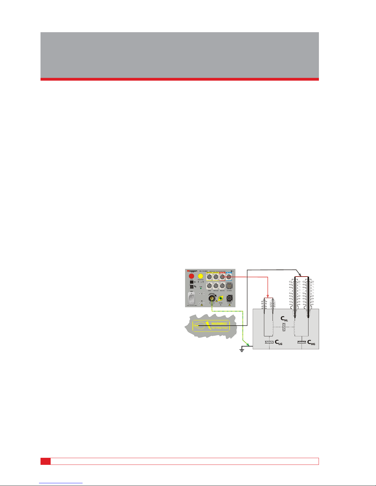
Figure 1 shows a simplied measuring circuit diagram of
the DELTA 4000 test set measuring a two-winding transformer
in UST test mode. The test voltage is connected to the HV
terminal and the current is measured at the LV terminal.
Voltage and current are accurately measured in amplitude
and phase and CHL capacitance, dissipation factor, power
loss etc are calculated and displayed.
Figure 1: UST-R test setup for a 2-w transformer
Dissipation factor measurements can generally be per-
formed with two different congurations, UST (Ungrounded Specimen Test) where the ground act as natural guard
or GST (Grounded Specimen Test) with or without guard.
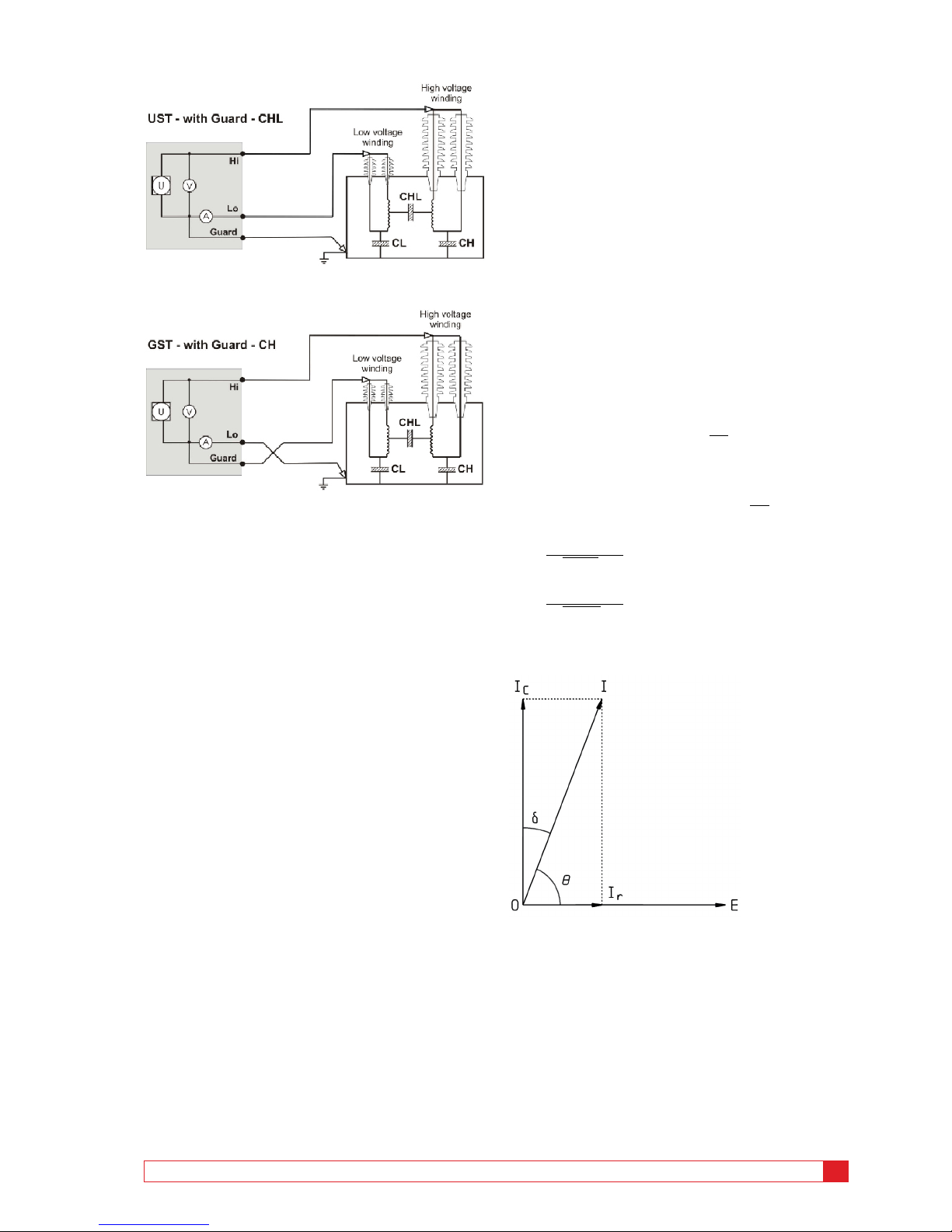
Figure 2 shows a guarded UST measurement. The current
owing through CHL is measured but the current paths
through CH and CL is guarded/grounded and not measured. Figure 3 shows a guarded GST measurement where
the CH current to ground is measured but the current
through CHL is guarded and measured.
General
The intention of this reference-application manual is to
guide the operator in the appropriate method of making
capacitance and dissipation factor/power factor measurements on power apparatus and to assist in the interpretation
of test results obtained. It is not a complete step-by-step
procedure for performing tests.
Before performing any test with this apparatus, read the
user manual and observe all safety precautions indicated.
Page 7
ZM-AH02E DELTA 4000
7
1 INTRODUCTION
Figure 2: UST connection for measuring CHL in a two-winding transformer
Figure 3: GST connection for measuring CH in a two-winding transformer
Current, capacitance and
dissipation factor relationship
In an ideal insulation system connected to an alternating
voltage source, the capacitance current Ic and the voltage
are in perfect quadrature with the current leading. In addition to the capacitance current, there appears in practice
a loss current Ir in phase with the voltage as shown in
Figure 5.
The current taken by an ideal insulation (no losses, I
r
= 0)
is a pure capacitive current leading the voltage by 90° (q =
90°). In practice, no insulation is perfect but has a certain
amount of loss and the total current I leads the voltage by
a phase angle q (q< 90°). It is more convenient to use the
dielectric-loss angle d, where d = (90° - q). For low power
factor insulation Ic and I are substantially of the same magnitude since the loss component Ir is very small.
The power factor is dened as:
Power factor= cos Θ = sin δ =
Ir
I
and the dissipation factor is dened as:
Dissipation factor = cot Θ = tan δ =
Ir
Ic
PF =
DF
•1+DF
2
DF =
PF
•1 – PF
2
The DELTA 4000 is able to display either dissipation factor
or power factor based on user’s choice.
Figure 5: Vector diagram insulation system
In cases where angle d is very small, sin d practically equals
tan d. For example, at power factor values less than 10
percent the difference will be less than 0.5 percent of reading while for power factor values less than 20 percent the
difference will be less than 2 percent of reading.
The value of I
c
will be within 99.5 percent of the value I
for power factor (sin d) values up to 10 percent and within
98 percent for power factor values up to 20 percent.
Page 8
8 DELTA 4000 ZM-AH02E
1 INTRODUCTION
Connections for UST/GST
Configurations
DELTA 4000 supports two basic groups of operation, GST
and UST mode. GST stands for grounded specimen test
while UST stands for ungrounded specimen test. Within
the two groups the test set can be operated in seven test
modes as summarized in Table 1.1. Measurements are
always made between the high-voltage lead and the lead/
connection in the measure column.
Table 1.1
DELTA 4000 test modes and internal measurement connections
UST: Ungrounded specimen testing
Tes t mo de Measure Ground Guard
UST- R Red Blue –
UST- B Blue Red –
UST- RB Red and Blue – –
GST: Grounded specimen testing
Tes t mo de Measure Ground Guard
GST- GND Ground Red and Blue –
GSTg-R Ground Blue Red
GSTg-B Ground Red Blue
GSTg-RB Ground – Red and Blue
In UST test mode, Ground and Guard are internally
connected. Internally the Red and Blue leads are either
connected to be measured or connected to Ground (and
Guard).
In GST test modes the current returning from Ground is
measured. Internally the Red and Blue leads are either connected to Ground or Guard to be included in or excluded
from the measurement.
Page 9

ZM-AH02E DELTA 4000
9
1 INTRODUCTION
Page 10

10 DELTA 4000 ZM-AH02E
2 INTERPRETATION OF MEASUREMENTS
in operation with consequent deterioration. Some increase
of capacitance (increase in charging current) may also be
observed above the extinction voltage because of the short
circuiting of numerous voids by the ionization process.
An increase of dissipation factor accompanied by in severe
cases possible increase of capacitance usually indicates
excessive moisture in the insulation. Increase of dissipation
factor alone may be caused by thermal deterioration or by
contamination other than water.
Unless bushing and pothead surfaces, terminal boards, etc.,
are clean and dry, measured quantities may not necessarily apply to the volume of the insulation under test. Any
leakage over terminal surfaces may add to the losses of the
insulation itself and may, if excessive, give a false indication
of its condition.
2
Interpretation of
measurements
Significance of capacitance and
dissipation factor
A large percentage of electrical apparatus failures are due
to a deteriorated condition of the insulation. Many of these
failures can be anticipated by regular application of simple
tests and with timely maintenance indicated by the tests.
An insulation system or apparatus should not be condemned until it has been completely isolated, cleaned, or
serviced and measurements compensated for temperature.
The correct interpretation of capacitance and dissipation
factor tests generally requires knowledge of the apparatus
construction and the characteristics of the particular types
of insulation used.
Changes in the normal capacitance of an insulation material
indicate such abnormal conditions as the presence of a
moisture layer, short circuits, or open circuits in the capacitance network. Dissipation factor measurements indicate
the following conditions in the insulation of a wide range
of electrical apparatus:
▪
Chemical deterioration due to time and temperature,
including certain cases of acute deterioration caused by
localized overheating.
▪
Contamination by water, carbon deposits, bad oil, dirt
and other chemicals.
▪
Severe leakage through cracks and over surfaces.
▪
Ionization.
The interpretation of measurements is usually based on
experience, recommendations of the manufacturer of the
equipment being tested, and by observing these differences:
▪
Between measurements on the same unit after successive
intervals of time.
▪
Between measurements on duplicate units or a similar
part of one unit, tested under the same conditions around
the same time, e.g., several identical transformers or one
winding of a three-phase transformer tested separately.
▪
Between measurements made at different test voltages
on one part of a unit; an increase in slope (tip-up) of a
dissipation factor versus voltage curve at a given voltage is
an indication of ionization commencing at that voltage.
An increase of dissipation factor above a typical value may
indicate conditions such as those given in the previous paragraph, any of which may be general or localized in charac-
ter. If the dissipation factor varies signicantly with voltage
down to some voltage below which it is substantially constant, then ionization is indicated. If this extinction voltage
is below the operating level, then ionization may progress
Page 11

ZM-AH02E DELTA 4000
11
2 INTERPRETATION OF MEASUREMENTS
Dissipation factor (Power
factor) of typical apparatus
insulation
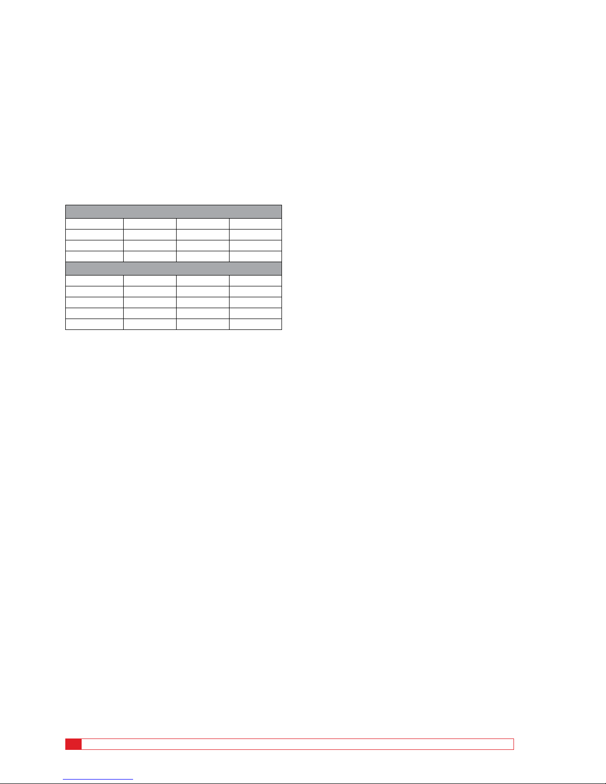
Values of insulation dissipation factor for various apparatus are shown in Table 2.1. These values may be useful in
roughly indicating the range to be found in practice. Please
note that the higher values are not to be regarded as “OK”
but instead examples of “to be investigated/at risk” data.
Table 2.1
DF (PF) of typical apparatus insulation
Type apparatus % DF (PF) at 20°C
Oil-filled transformer: New, highvoltage (115 kV and up)
0.25 to 1.0
15 years old, high-voltage 0.25--
Low-voltage, distribution type 0.30-Oil circuit breakers 0.5 to 2.0
Oil-paper cables, “solid” (up to 27.6
kV) new condition
0.5 to 1.5
Oil-paper cables, high-voltage oil-filled
or pressurized
0.2 to 0.5
Rotating machine stator windings, 2.3
to 13.8 kV
2.0 to 8.0
Capacitors (discharge resistor out of
circuit)
0.2 to 0.5
Bushings: Solid or dry 3.0 to 10.0
Compound-filled, up to 15 kV 5.0 to 10.0
Compound-filled, 15 to 46 kV 2.0 to 5.0
Oil-filled, below 110 kV 1.5 to 4.0
Oil-filled, above 110 kV and con-
denser type
0.25--
In IEEE 62-1995, typical values for dissipation/power factor are given as in Table 2.2.
Table 2.2
IEEE 62-1995 power factor values
Typical power factor values @ 20°C
“New” “Old” Warning/alert limit
Power transformers, oil
insulated
0.2-0.4% 0.3-0.5% > 0.5%
Bushings
0.2-0.3% 0.3-0.5% > 0.5%
IEEE 62-1995 states; “The power factors recorded for
routine overall tests on older apparatus provide information
regarding the general condition of the ground and interwinding insulation of transformers and reactors. While the
power factors for older transformers will also be <0.5%
(20°C), power factors between 0.5% and 1.0% (20°C) may
be acceptable; however, power factors >1.0% (20°C) should
be investigated.”
Permittivity and % DF of
typical insulating materials
Typical values of permittivity (dielectric constant) k and
50/60 Hz dissipation factor of a few kinds of insulating
materials (also water and ice) are given in Table 2.3.
Table 2.3
Permittivity and dissipation factor of typical
insulating materials
Material k % DF (PF) at 20°C
Acetal resin (Delrin*) 3.7 0.5
Air 1.0 0.0
Askarels 4.2 0.4
Kraft paper, dry 2.2 0.6
Oil, transformer 2.2 0.02
Polyamide (Nomex*) 2.5 1.0
Polyester film (Mylar*) 3.0 0.3
Polyethylene 2.3 0.02-0.05
Polyamide film (Kapton*) 3.5 0.3
Polypropylene 2.2 0.05
Porcelain 7.0 2.0
Rubber 3.6 4.0
Silicone liquid 2.7 0.01
Varnished cambric, dry 4.4 1.0
Water** 80 100
Ice** 88 1.0 (0°C)
* Dupont registered trademark.
** Tests for moisture should not be made at freezing tempera-
tures because of the 100 to 1 ratio difference of % dissipation
factor between water and ice.
Page 12

12 DELTA 4000 ZM-AH02E
2 INTERPRETATION OF MEASUREMENTS
Any sudden changes in ambient temperature will increase
the measurement error since the temperature of the apparatus will lag the ambient temperature.
Dissipation factor-temperature characteristics, as well as
dissipation factor measurements at a given temperature,
may change with deterioration or damage of insulation.
This suggests that any such change in temperature characteristics may be helpful in assessing deteriorated condi-
tions. As an example, bushings have typically a rather at
temperature correction with only slightly elevated values
at high temperatures. Generally a bushing showing highly
increased dissipation factor at elevated temperature should
be considered “at risk”.
Be careful making measurements below the freezing point
of water. A crack in an insulator, for example, is easily
detected if it contains a conducting lm of water. When
the water freezes, it becomes non-conducting, and the
defect may not be revealed by the measurement, because ice
has a volumetric resistivity approximately 100 times higher
than that of water. Moisture in oil, or in oil-impregnated
solids, has been found to be detectable in dissipation factor
measurements at temperatures far below freezing, with no
discontinuity in the measurements at the freezing point.
Insulating surfaces exposed to ambient weather conditions
may also be affected by temperature. The surface temperature of the insulation specimen should be above and never
below the ambient temperature to avoid the effects of
condensation on the exposed insulating surfaces.
Significance of temperature
Most insulation measurements have to be interpreted based
on the temperature of the specimen. The dielectric losses
of most insulation increase with temperature; however, e.g.
dry oil-impregnated paper and polyethylene of good quality
exhibit decrease of dielectric losses when temperature is
raised moderately, e.g. from 20°C to 30°C. It is also known
that the effect of temperature depends on the aging status
of the insulation. In many cases, insulations have failed due
to the cumulative effect of temperature, i.e., a rise in temperature causes a rise in dielectric loss which in turn causes
a further rise in temperature, etc (thermal runaway).
It is important to determine the dissipation factor-temperature characteristics of the insulation under test. Otherwise,
all tests of the same specimen should be made, as nearly as
practicable, at the same temperature.
To compare the dissipation factor value of tests made on
the same or similar type apparatus at different temperatures,
it is necessary to convert the value to a reference temperature base, usually 20°C (68°F). Examples of standard tables
of multipliers for use in converting dissipation factors at
test temperatures to dissipation factors at 20°C are found in
the Appendix A of this document.
In reality, temperature correction for a specic component is always individual and pending age/condition.
DELTA 4000 has a unique and patented feature for estimating the individual temperature correction (ITC). By measuring dissipation factor over frequency and using mathematical formulas and models of insulation characteristics, the
correct temperature correction can be determined from
5 to 50°C measurement temperature to 20°C reference
temperature. The input data for the calculation is dissipation factor measured from 1 to 500 Hz and the method
is principally based on Arrhenius’ law, describing how the
insulation properties are changing over temperature.
κ = κ
0
·exp(-Wa/kT)
With activation energy W
a
and Boltzmann constant k
The test temperature for apparatus such as spare bushings,
insulators, air or gas lled circuit breakers, and lightning
arresters is normally assumed to be the same as the ambient
temperature. For oil-lled circuit breakers and transformers the test temperature is assumed to be the same as the
top oil temperature or winding temperature. For installed
bushings where the lower end is immersed in oil the test
temperature lies somewhere between the oil and air temperature.
In practice, the test temperature is assumed to be the same
as the ambient temperature for bushings installed in oil-
lled circuit breakers and also for oil-lled transformers
that have been out of service for approximately 12 hours.
In transformers removed from service just prior to test,
the temperature of the oil normally exceeds the ambient
temperature. The bushing test temperature for this case can
be assumed to be the midpoint between the oil and ambient
temperatures.
Page 13

ZM-AH02E DELTA 4000
13
2 INTERPRETATION OF MEASUREMENTS
Significance of humidity
The exposed surface of bushings may, under adverse relative humidity conditions, acquire a deposit of surface mois-
ture which can have a signicant effect on surface losses
and consequently on the results of a dissipation factor test.
This is particularly true if the porcelain surface of a bush-
ing is at a temperature below ambient temperature (below
dew point), because moisture will probably condense on the
porcelain surface. Serious measurement errors may result
even at a relative humidity below 50 percent when moisture
condenses on a porcelain surface already contaminated with
industrial chemical deposits.
It is important to note that an invisible thin surface lm of
moisture forms and dissipates rapidly on materials such as
glazed porcelain which have negligible volume absorption.
Equilibrium after a sudden wide change in relative humidity is usually attained within a matter of minutes. This,
however, excludes thicker lms which result from rain, fog,
or dew point condensation.
Surface leakage errors can be minimized if dissipation
factor measurements are made under conditions where the
weather is clear and sunny and where the relative humidity does not exceed 80 percent. In general, best results are
obtained if measurements are made during late morning
through mid afternoon. Consideration should be given to
the probability of moisture being deposited by rain or fog
on equipment just prior to making any measurements.
Surface leakage
Any leakage over the insulation surfaces of the specimen
will be added to the losses in the volume insulation and may
give a false impression as to the condition of the specimen.
Even a bushing with a voltage rating much greater than the
test voltage may be contaminated enough to cause a signicant error. Surfaces of potheads, bushings, and insulators
should be clean and dry when making a measurement.
It should be noted that a straight line plot of surface resistivity against relative humidity for an uncontaminated porcelain bushing surface results in a decrease of one decade
in resistivity for a nominal 15 percent increase in relative
humidity and vice versa.
On bushings provided with a power factor or capacitance
tap, the effect of leakage current over the surface of a
porcelain bushing may be eliminated from the measurement
by testing the bushing by the ungrounded specimen test
(UST).
When testing bushings without a test tap under high
humidity conditions, numerous companies have reported
that the effects of surface leakage can be substantially
minimized by cleaning and drying the porcelain surface and
applying a very thin coat of Dow Corning #4 insulating
grease (or equal) to the entire porcelain surface. When making a hot collar test, the grease is generally only applied to
the porcelain surface on which the hot collar band is to be
located and to that of one petticoat above and one below
the hot collar band.
When testing potheads, bushings (without test tap), and
insulators under unfavorable weather conditions, the dissipation factor reading may, at times, appear to be unstable
and may vary slightly over a very short period of time. The
variation is caused by such factors as the amount of surface
exposure to sun or shade, variations in wind velocity, and
gradual changes in ambient temperature and relative humidity. Similar bushings may have appreciably different dissipation factor values for the case where one bushing is located
in the sun while the other is in the shade. A test made on
the same bushing may have a different dissipation factor
value between a morning and an afternoon reading. Due
consideration must be given to variations in readings when
tests are made under unfavorable weather conditions.
Page 14

14 DELTA 4000 ZM-AH02E
2 INTERPRETATION OF MEASUREMENTS
Negative dissipation factor
Creep currents inside an insulation system or more commonly on surfaces; create change of potential distribution
that may give increased or decreased dissipation factor, and
in some cases also negative dissipation factor. This condition is most likely to arise when making UST and GST
measurements on specimens who have a capacitance value
of a few hundred picofarad or less. Equipment such as
bushings, circuit breakers, and low loss surge arresters fall
into this category.
The error is usually accentuated if tests are made under
unfavorable weather conditions, especially a high relative
humidity which increases surface leakage.
There appears to be no clear-cut way of knowing whether
an error is signicant or what remedies should be taken to
overcome an error. A frequency sweep may give additional
information. The best advice is to avoid making measurements on equipment in locations where negative dissipation
factors are known to present a problem when unfavorable
weather conditions exist, especially high relative humidity.
Make sure the surface of porcelain bushings are clean and
dry to minimize the effects of surface leakage. Make sure all
items such as wooden ladders or nylon ropes are removed
from the equipment to be tested and are brought out of
any electrostatic interference elds that could inuence a
measurement.
Connected bus work, cables etc
A complete disconnected component is preferred when
performing dissipation factor measurements. All connected
bus work, cables, disconnect switches etc may add signicant capacitance and losses in GST measurements where
they are in parallel with the desired insulation measurement. For this reason, many test engineers will ask that the
equipment under test be totally isolated from connected
apparatus.
UST data is principally possible to measure without fully
disconnecting the test object. The capacitance from the
connected parts results only in a current to ground that is
not measured in UST test mode.
Electrostatic interference
When tests are conducted in energized substations, the
readings may be inuenced by electrostatic interference
currents resulting from the capacitive coupling between
energized lines and bus work to the test specimen. Other
sources for interference may be corona discharges (especially at high humidity) and is some cases DC uctuations
in the grounding system. Trouble from magnetic elds
encountered in high-voltage substations is very unlikely.
To counter the effects of severe electrostatic interference
on the measurement, it may be necessary to disconnect the
specimen from disconnect switches and bus work. Experience in making measurements will establish the particular
equipment locations where it is necessary to break the
connections. The related disconnect switches, leads and
bus work, if not energized, should be solidly grounded to
minimize electrostatic coupling to the test set.
The measurement difculty which is encountered when
testing in the presence of interference depends not only
upon the severity of the interference eld but also on the
capacitance and dissipation factor of the specimen. Unfavorable weather conditions such as high relative humidity,
fog, overcast sky, and high wind velocity will increase the
severity and variability of the interference eld. The lower
the specimen capacitance and its dissipation factor, the
greater the difculty is to perform accurate measurements.
It is also possible that a negative dissipation factor reading
may be obtained so it is necessary to observe the polarity
sign for each reading. Specically, it has been found that
some difculty may be expected when measuring capaci-
tance by the GST test method in high interference switchyards when the capacitance value is less than 100 pF. This
difculty may be minimized considerably by:
▪
Using the maximum voltage of the test set if possible.
▪
Disconnecting and grounding as much bus work as
possible from the specimen terminals.
▪
Making measurements on a day when the weather
is sunny and clear, the relative humidity is less than
80 percent, the wind velocity is low, and the surface
temperature of exposed insulation is above the ambient
temperature.
Tests made by the UST method are less susceptible to interference pickup than are tests made by the GST method.
In the UST test method, the capacitive coupled pickup
current in the high-voltage circuit ows directly to ground
after having passed through the high-voltage winding of
the power supply transformer. In the GST test method the
same pickup current, after passing through the high-voltage
transformer winding, must pass through one of the bridge
transformer-ratio measuring arms before reaching ground.
Page 15

ZM-AH02E DELTA 4000
15
2 INTERPRETATION OF MEASUREMENTS
Page 16

16 DELTA 4000 ZM-AH02E
3 TESTING POWER SYSTEM COMPONENTS
▪
Autotransformer: A transformer in which at least two
windings have a common section.
▪
Excitation Current (No-Load Current): The current which
flows in any winding used to excite the transformer when
all other windings are open-circuited.
▪
Tap (in a transformer): A connection brought out of a
winding at some point between its extremities, to permit
changing the voltage, or current, ratio.
▪
Delta Connection: So connected that the windings of a
three-phase transformer (or the windings for the same
rated voltage of single-phase transformers associated in
a three- phase bank) are connected in series to form a
closed circuit.
▪
Y (or Wye) Connection: So connected that one end of
each of the windings of a polyphase transformer (or of
each of the windings for the same rated voltage of singlephase transformers associated in a polyphase bank) is
connected to a common point (the neutral point) and
other end to its appropriate line terminal.
▪
Zigzag Connection: A polyphase transformer with
Y-connected windings, each one of which is made up of
parts in which phase-displaced voltages are induced.
▪
Tertiary Winding: The third winding of the transformer
and often provides the substation service voltage, or in
the case of a wye-wye connected transformer, it prevents
severe distortion of the line-to-neutral voltages.
The following equipment and tests will be discussed in this
guide:
▪
Two-Winding Transformers
▪
Three-Winding Transformers
▪
Autotransformer
▪
Transformer Excitation Current Tests
▪
Shunt Reactors
▪
Potential Transformers
▪
Current Transformers
▪
Voltage Regulators
▪
Dry-Type Transformers
Two-winding transformers
Two-winding transformer measurement is described in
Figure 10.
3
Testing power system
components
Transformers
Introduction
The transformer is probably one of the most useful electrical devices ever invented. It can raise or lower the voltage
or current in an ac circuit, it can isolate circuits from each
other, and it can increase or decrease the apparent value
of a capacitor, an inductor, or a resistor. Furthermore, the
transformer enables us to transmit electrical energy over
great distances and to distribute it safely in factories and
homes. Transformers are extensively used in electric power
systems to transfer power by electromagnetic induction between circuits at the same frequency, usually with changed
values of voltage and current.
Dissipation/Power factor testing is an effective method to
detect and help isolate conditions such as moisture, carbonization, and contamination in bushings, windings and liquid
insulation. In addition to power factor testing, transformer
excitation current measurements will help detect winding
and core problems.
The voltage rating of each winding under test must be considered and the test voltage selected accordingly. If neutral
bushings are involved, their voltage rating must be considered in selecting the test voltage. Measurements should be
made between each inter-winding combination (or set of
three-phase windings in a three-phase transformer) with all
other windings grounded to the tank (UST test). Measurements should also be made between each winding (or set of
three-phase windings) and ground with all other windings
guarded (GST test with guard).
In a two-winding transformer, a measurement should
also be made between each winding and ground with the
remaining winding grounded (GST-GND test). For a
three-winding transformer, a measurement should also be
made between each winding and ground with one remaining winding guarded and the second remaining winding
grounded (GSTg test). This special test is used to isolate the
inter-windings. A nal measurement should be made be-
tween all windings connected together and the ground tank.
It is also desirable to test samples of the liquid insulation.
Definitions
▪
Step-Down Transformer: A transformer in which the
power transfer is from the higher voltage source circuit to
a lower voltage circuit.
▪
Step-Up transformer: A transformer in which the power
transfer is from the lower voltage source circuit to a
higher voltage circuit.
Page 17

ZM-AH02E DELTA 4000
17
3 TESTING POWER SYSTEM COMPONENTS
Figure 10: Two-Winding Transformer Test
Test connections
For all transformer testing, including spare transformers,
ensure the following safety conditions are observed:
Test connections are dened in table 3.1.
Table 3.1
Two-winding transformer test connections
Tes t No .
Insulation tested
Low voltage
lead configuration
Tes t
lead
connections to
wind-
ings
Remarks
Tes t mo de
Measure
Ground
Guard
High voltage
Red
Blue
1
CHG+
CHL
GSTGND
Red &
Blue
H L – L Grounded
2 CHG GSTg-RB
Red &
Blue
H L – L Guarded
3 CHL UST- R Red Blue H L –
4 CHL – Test 1 minus Test 2 – – –
Calculated
intercheck
5
CLG +
CHL
GSTGND
Red &
Blue
L H –
H Grounded
6 CLG GSTg-RB
Red &
Blue
L H – H Guarded
7 CLH UST-RB Red Blue L H –
8 LH – Test 5 minus Test 6 – – –
Calculated
intercheck
Equivalent circuit
Note: Short each winding on itself.
Measurement Inter-checks (Calculated)
Capacitance Watts
C
4
= C1 - C
2
W4 = W1 - W
2
C8 = C5 - C
6
W8 = W5 - W
6
Note: Subscripts are test numbers
H
High-voltage winding
L
Low-voltage winding
G
Ground
1] The transformer must be taken out of service and
isolated from the power system.
2] Ensure the transformer is properly grounded to the
system ground.
3] Before applying any voltage on the transformer
make sure that all bushing current transformers
are shorted out.
4] Never perform electrical tests of any kind on a unit
under vacuum. Flashovers can occur at voltages as
low as 250 volts.
5] If the transformer is equipped with a load tap
changer, set the unit to some step off of neutral.
Some load tap changers are designed with arrester
type elements that are not effectively shorted out
in the neutral position even with all the bushings
shorted.
6] Connect a ground wire from the test set to the
transformer ground.
7] Short all bushings of each winding including the
neutral of a wye-connected winding. The neutral
ground must also be removed. The shorting wire
must not be allowed to sag.
8] Connect the high voltage lead to the high side
bushings for tests 1, 2, and 3. Ensure that the high
voltage cable extends out away from the bushing.
9] Connect the red low voltage lead to the low volt-
age bushings.
10] For tests 5, 6 and 7, connect the high voltage lead
from the test set to the low voltage bushings of
the transformer and the red low voltage lead from
the test set to the high voltage bushings.
11] Individual tests should be performed on each bush-
ing. Bushings equipped with a potential/test tap
should have the UST test performed and the GST
on those without test taps.
Hot collar tests can if necessary be performed on
both types.
Page 18

18 DELTA 4000 ZM-AH02E
3 TESTING POWER SYSTEM COMPONENTS
8] Correct the power factor readings of the trans-
former to 20°C using individual temperature correction or standard tables
9] Identify each set of readings of the transformer
bushings with a serial number. Record manufacture, type or model and other nameplate ratings.
Especially be aware to record nameplate C
1
capacitance and power factor values if available. Correct
the power factor readings on the bushings to 20°C
Test results
Power factor results should always be compared to manufacturers’ tests, or to prior test results if available. It is impossible to set maximum power factor limits within which
all transformers are acceptable, but units with readings
above 0.5% at 20°C should be investigated.
Oil-lled service-aged transformers may have slightly
higher results and should be trended to identify signicant
changes.
Bushings, if in poor condition, may have their losses
masked by normal losses in the winding insulation Therefore, separate tests should be applied to them.
Increased power factor values, in comparison with a previous test or tests on identical apparatus, may indicate some
general condition such as contaminated oil. An increase in
both power factor and capacitance indicates that contamination is likely to be water. When the insulating liquid is be-
ing ltered or otherwise treated, repeated measurements on
windings and liquid will usually show whether good general
conditions are being restored.
Oil oxidation and consequent sludging conditions have a
marked effect on the power factors of transformer wind-
ings. After such a condition has been remedied, (ushing
down or other treatment) power factor measurements are
valuable in determining if the sludge removal has been effective.
Measurements on individual windings may vary due to differences in insulation materials and arrangements.
However, large differences may indicate localized deterioration or damage. Careful consideration of the measurements
on different combinations of windings should show in
which particular path the trouble lies; for example, if a measurement between two windings has a high power factor,
and the measurements between each winding and ground,
with the remaining winding guarded, gives a normal reading, then the trouble lies between the windings, perhaps in
an insulating cylinder.
Three-winding transformers
Testing of three-winding transformers is performed in
the same manner as two-winding transformers with the
additional tests of the tertiary winding. In some cases
transformers are constructed so that the inter-windings are
shielded by a grounded electrostatic shield or a concentricwinding arrangement. This could provide test results that
capacitance is almost non-existent or even a negative power
factor. The transformer manufacturer should be contacted
12]
Transformer windings must remain shorted for all
bushing tests. Windings not energized must be
grounded.
13] For transformers that have wye-wye configuration,
and the neutrals internally cannot be separated,
1-3 and 5-7 cannot be measured. In this case short
the high voltage bushings and the low voltage
bushings together and perform a GST test. Test
voltage should be suitable for the rating of the
low voltage winding.
Test procedure
For all power factor testing, the more information you
record at the time of testing will ensure the best comparison of results at the next routine test. Test data should be
compared to the nameplate data. If nameplate or factory
readings are not available, compare the results of prior
tests on the same transformer or results of similar tests on
similar transformers. If at all possible, power factor and
capacitance readings should be taken on all new transformers for future benchmarking.
Field measurements of power-factor and capacitance can
differ from measurements made under the controlled
conditions in the factory. Therefore, the power-factor and
capacitance should be measured at the time of installation
and used as a base to compare future measurements. Power
factor testing is extremely sensitive to weather conditions.
Tests should be conducted in favorable conditions whenever possible. All tests are performed at 10kV. If these values
exceed the rating of the winding, test at or slightly below
the rating.
1]
Follow the test sequence of the Two-Winding
Transformers Test Connections. Tests 1, 2 and 3 can
be completed without a lead change.
2] Test 4 is a calculation subtracting the capacitance
and watts results in test 2 from test 1. The results
should compare with the UST measurement for the
C
HL
insulation
3] Reverse the test leads for tests 5, 6 and 7. Test volt-
age should be at a level suitable for the secondary
winding of the transformer.
4] Test 8 is a calculation by subtracting test 6 from
test 5. Results should compare with the UST measurement in test 7 for the C
HL
insulation.
5] Enter all the nameplate information of the trans-
former. Note any special or unusual test connections or conditions.
6] Enter ambient temperature and relative humidity
and a general indication of weather conditions at
the time of the test.
7] Enter the insulation temperature (top oil or wind-
ing temperature)
Page 19

ZM-AH02E DELTA 4000
19
3 TESTING POWER SYSTEM COMPONENTS
to verify the existence of a shield or a concentric-winding
arrangement.
Three-winding transformer test connections are described
in Table 3.2.
Table 3.2
Three-winding transformer test connections
Tes t No .
Insulation tested
Low voltage lead
configuration
Test lead
connections to
windings
Remarks
Tes t mo de
Measure
Ground
Guard
High voltage
Red
Blue
1
CHG+
CHL
GSTg-B Red Blue H L T
L Grounded
T Guarded
2 CHG
GSTg-
RB
Red &
Blue
H L T
L & T
Guarded
3 CHL UST-R Red Blue H L T T Grounded
4 CHL – Test 1 minus Test 2 – – –
Calculated
intercheck
5
CLG +
CLT
GSTg-
BR
Blue Red L H T
T Grounded
H Guarded
6 CLG
GSTg-
RB
Red &
Blue
L H T
T & H
Guarded
7 CLT UST- RB Blue Red L H T H Grounded
8 CLT – Test 5 minus Test 6 – – –
Calculated
intercheck
9
CTG +
CHT
GSTg-B Red Blue T H L
H Grounded
L Guarded
10 CTG
GSTg-
RB
Red &
Blue
T H L
H & L
Guarded
11 CHT UST-R Red Blue T H L L Grounded
12 CHT – Test 9 minus Test 10 – – –
Calculated
intercheck
Equivalent Circuit
Note: Short each winding on
itself.
Measurement Interchecks (Calculated)
Capacitance Watts
C
4
= C1 - C
2
W4 = W1 - W
2
C8 = C5 - C
6
W8 = W5 - W
6
C12 = C9 - C
10
W12 = W9 - W
10
Note: Subscripts are test num-
bers
H High-voltage winding
L Low-voltage winding
T Tertiary winding
G Ground
Autotransformers
In the design of an autotransformer, the secondary winding
is actually part of the primary winding. For a given power
output, an autotransformer is smaller and cheaper than a
conventional transformer. This is particularly true if the
ratio of the incoming line voltage to outgoing line voltage
lies between 0.5 and 2.
Autotransformers may have a tertiary winding. If so, both
primary and secondary bushings are shorted together and
the tertiary bushings are shorted to each other. The autotransformer is then tested as a two winding transformer.
Individual tests should be performed on each bushing if
they are equipped with a test tap.
If the autotransformer does not have a tertiary winding,
short the high voltage bushings and the low voltage bushings together and perform a GST test. Test voltage should
be suitable for the rating of the low voltage winding
Transformer excitation current tests
Transformer excitation current tests are helpful in determining possible winding or core problems in transformers,
even when ratio and winding resistance tests appear normal.
Excitation tests should be conducted routinely along with
power factor testing.
Test connections
Test connection described in table 3.3.
Page 20

20 DELTA 4000 ZM-AH02E
3 TESTING POWER SYSTEM COMPONENTS
Table 3.3
Transformer excitation current test connections
Single phase
Measure Test lead connections
Terminal symbol High voltage Red Ground
H1-H2 H1 H2 –
H2-H1 H2 H1 –
Three phase high side “Y”
Measures Test lead connections
Terminal symbol High voltage Red Ground
H1-H0 H1 H0 –
H2-H0 H2 H0 –
H3-H0 H3 H0 –
Three phase high side “∆“
Measures Test lead connections
Terminal symbol High voltage Red Ground
H1-H2 H1 H2 H3
H2-H3 H2 H3 H1
H3-H1 H3 H1 H2
▪
Transformer excitation current tests are performed on the
high voltage winding to minimize the excitation current.
Problems in the low voltage windings will still be detected
by this method.
▪
The secondary windings are left floating with the
exception of a wye or zig-zag secondary. In this case
the neutral bushing remains grounded as it is in normal
service. Refer to the user manual for test connections for
Single Phase, Three Phase High Side Wye and Three Phase
High Side Delta transformers.
▪
Single Phase: The transformer is energized from the phase
to neutral bushings (ANSI: H1-H2). Test connections can
be reversed for additional data, but test results should be
the same. H2 may also be designated as H0.
▪
Wye – Wye: Observe that the ground wire is removed
from the high voltage side neutral bushing for testing,
but remains connected on the low voltage side neutral
bushing.
Test procedure
▪
Test voltages should be as high as possible, but limited
to 10 kV, without exceeding the rating of the line-to-line
voltages on delta connected transformers and line-toground on wye connected transformers. Also note that in
many cases the maximum applied voltage is limited by the
maximum current output
▪
Test voltage must always be the same as prior tests if any
comparisons are made.
▪
All transformer excitation current tests are conducted in
the UST test mode (normally UST-R, using Red low voltage
lead).
▪
For routine testing, transformers with load tap changers
should have tests performed in at least one raise and one
lower position off of neutral. The no-load tap changer
should be in the normal in service position.
▪
For new transformers, excitation tests should be
performed in every tap position for both the load and noload tap changers.
▪
The more information that is recorded at the time of
testing will ensure the best comparison of results at the
next routine test.
▪
Temperature corrections are not applied to transformer
excitation current tests.
Test results
Compare test results to previous tests on the same transformer, or to manufacturers’ data if available. Tests can also
be compared to similar type units. It is essential that identical test voltages be used for repeat tests on a transformer.
Fluctuation in the test voltage will produce inconsistent
current readings. Three phase transformers should have the
individual windings energized at both ends if the original
test appears abnormal.
Transformer excitation current tests on the high voltage
winding should detect problems in the secondary winding
if they exist. Winding resistance testing in addition to the
excitation tests could be helpful in isolating either a core or
winding defect.
Test results on three phase transformers, especially wyeconnected windings, could produce high but similar readings on two phases compared to the third phase. This is
Page 21

ZM-AH02E DELTA 4000
21
3 TESTING POWER SYSTEM COMPONENTS
the result of the low phase being wound around the center
leg of a three-legged core. The reluctance of the magnetic
circuit is less for the center leg of the core resulting in a
lower charging current.
Shunt reactors
When electrical energy is transmitted at extra high voltages,
special problems arise that require the installation of large
compensating devices to regulate the over-voltage conditions and to guarantee stability. Among these devices are
shunt reactors. Shunt reactors are composed of a large coil
placed inside a tank and immersed in oil. They can be single
phase units or three phases in one tank. In both cases each
phase has its own neutral bushing.
Test connections
▪
For all tests, the line and neutral bushings for
corresponding phases must remain shorted.
Test procedure
▪
Record test results on the test form for Miscellaneous
Equipment Capacitance and Power Factor Tests.
▪
Test voltages are at 10kV. If 10kV exceeds the insulation
rating, test at or slightly below the insulation rating.
▪
For single phase units only one overall ground test is
performed in the GST mode.
Test results
Power factor and capacitance results should be recorded in
the same manner as for oil lled power transformers. Temperature correction should be to the top oil temperature.
Compare test results to previous tests or tests on similar
units. Additional bushing tests should be performed if test
results are suspect.
Potential transformers
Potential transformers are installed on power systems for
the purpose of stepping down the voltage for the operation
of instruments such as Volt-meters, Watt-meters and relays
for various protective purposes. Typically the secondary
voltage of potential transformers is 120 V, so power factor
testing is performed on the primary winding. Potential
transformers are typically single phase with either single or
two bushing primaries. Single bushing primaries have one
end of the high voltage winding connected to ground. Secondary windings are normally three wire and dual identical
secondary windings are common.
Test connections
Ensure that the potential transformer is disconnected from
the primary source before testing begins.
1]
Remove any fusing on the secondary circuits to
prevent any type of back-feeding to the secondary.
2] Ground one leg of each secondary winding for all
tests on two primary bushing transformers, for
dual secondary transformers it is typically X1 and
Y1.
3] Ensure that the case of the potential transformer
is securely grounded to a system ground before
testing begins, this also includes testing of spare
transformers.
Test procedure
Ensure the test set is securely grounded.
1]
Record all tests results. Power factor tests should
be corrected to ambient temperature.
2] Compare test results to prior tests on the same or
similar equipment.
Current transformers
Current transformers are used for stepping down primary
current for Ampere-meters, Watt-meters and for relaying.
Typical secondary current rating is 5 A. Current transformers have ratings for high voltage and extra high voltage
application. The higher voltage classications can be oiled
lled, dry type or porcelain construction. Tests on two
bushing primary currents transformers are performed
by shorting the primary winding, grounding all secondary windings and test in the GST mode. Some current
transformers in the high voltage classications have test
taps similar to bushings. Tests can be performed on units
equipped with a test tap for the C1 insulation and the C2
tap insulation. Assure that the unit under test is grounded
before testing. Record all test results and correct the power
factor readings to the ambient temperature at the time of
the test.
Voltage regulators
Regulators are generally induction or step-by- step. The
induction regulator is a special type of transformer, built
like an induction motor with a coil-wound secondary, which
is used for varying the voltage delivered to a synchronous
converter or an ac feeder system. The step-by-step regulator
is a stationary transformer provided with a large number of
secondary taps and equipped with a switching mechanism
for joining any desired pair of these taps to the delivery
circuit. Voltage regulators may be single or three phase.
Single phase regulators consist of three bushings identied
as S (Source), L (Load) and SL (Neutral). The windings in
the regulator cannot be effectively separated, so one overall
power factor test is performed. All the bushings are shorted
together and tested in the GST-GND test mode.
Tests should be conducted with the tap changer moved to
some position off of neutral. Additional Hot Collar tests
may be conducted on bushings of suspect units. Excitation
tests may also be performed by energizing terminal L with
the high voltage lead and the low voltage lead on SL in the
UST position. Terminal S should be left oating. Power
factor results should be corrected to top oil temperature on
regulators just taken out of service. Ambient temperature
should be used for those that have been out of service for
any length of time. Power factor results should be compare
to previous tests on the same equipment or similar tests on
similar units.
Page 22

22 DELTA 4000 ZM-AH02E
3 TESTING POWER SYSTEM COMPONENTS
Dry-type transformers
Testing notes
Test voltages should be limited to line-to-ground ratings
of the transformer windings. Insulation power factor tests
should be made from windings to ground and between
windings. Temperature at the time of testing should be at
or near 20°C. ANSI/IEEE C57.12.91 - 1997 recommends
correcting results other than 20°C. However, there is very
little data available for temperature correction of dry-type
transformers. Repeat tests should be performed as near as
possible, in the same conditions as the original test.
Higher overall power factor results may be expected on drytype transformers. The majority of test results for power
factor is found to be below 2.0%, but can range up to 10%.
The insulation materials necessary for dry-type construction, must meet the thermal and stress requirements.
If power factor results appear to be unacceptable, an additional Tip-Up Test can be performed if a 10kV test set
is used. This test can be performed to evaluate whether
moisture or corona is present in the insulation system.
The applied test voltage is varied starting at about 1kV and
increased in intervals up to 10 kV or the line-to-ground rating of the winding insulation. If the power factor does not
change as the test voltage is increased, moisture is suspected
to be the probable cause. If the power factor increases as
the voltage is increased, carbonization of the insulation or
ionization of voids is the cause.
Note DELTA 4000 has a specific feature where the
test set recognizes voltage dependence and
will automatically indicate a non-linear behavior and by this indicate to the user to perform
a tip-up test
Bushings
Introduction
Bushings provide an insulated path for energized conductors to enter grounded electrical power apparatus. Bushings
are a critical part of the electrical system that transforms
and switches ac voltages ranging from a few hundred volts
to several thousand volts. Bushings not only handle high
electrical stress, they could be subjected to mechanical
stresses, afliated with connectors and bus support, as well.
Although a bushing may be thought of as somewhat of a
simple device, its deterioration could have severe consequences.
All modern bushings rated 23 kV and higher have a power
factor or a capacitance tap which permits dissipation factor
testing of the bushing while it is in place on the apparatus
without disconnecting any leads to the bushing. The dissipation factor is measured by the ungrounded specimen
test (UST) which eliminates the inuence of transformer
winding insulation, breaker arc-interrupters, or support
structures which are connected to the bushing terminal.
Figure 11 shows the test connections between the test set
and bushing when using the UST test mode.
1]
Connect test ground to apparatus ground.
2] Connect the high-voltage lead to the terminal at
the top of the bushing and the low-voltage lead
(red) to the power factor tap.
3] Ground the apparatus tank. The tap is normally
grounded through a spring and it is necessary,
when making measurements, to remove the
plug which seals and grounds the tap. Use the
UST measure red, ground blue test mode setting
(UST-R).
The UST test also can be used for making measurements
on bushings which have provisions for ange isolation. The
normal method of isolating the ange from the apparatus
cover is to use insulating gaskets between the ange and
cover and insulating bushings on all but one of the bolts
securing the mounting ange to the cover. During normal
operation, the ange is grounded by a single metal bolt;
however, when testing the bushing, this bolt is removed.
The measurement is identical to that when testing bushings
which have a power factor tap except that the low-voltage
lead, red in this case, is connected to the isolated bushing
ange.
Definitions
Bushing voltage tap
A connection to one of the conducting layers of a capacitance graded bushing providing a capacitance voltage divid-
er. Note: additional equipment can be designed, connected
to this tap and calibrated to indicate the voltage applied to
the bushing. This tap can also be used for measurement of
power factor and capacitance values.
Page 23

ZM-AH02E DELTA 4000
23
3 TESTING POWER SYSTEM COMPONENTS
Bushing test tap
A connection to one of the conducting layers of a capacitance graded bushing for measurement of power factor and
capacitance values.
Capacitance (of bushing)
(1) the main capacitance, c1, of a bushing is the capacitance
between the high-voltage conductor and the voltage tap or
test tap.
(2) the tap capacitance, c
2, of a capacitance graded bushing
is the capacitance between the voltage tap and mounting
ange (ground).
(3) the capacitance, c, of a bushing without a voltage or test
tap is the capacitance between the high-voltage conductor
and the mounting ange (ground).
Capacitance graded bushing
A bushing in which metallic or non-metallic conducting
layers are arranged within the insulating material for the
purpose of controlling the distribution of the electric eld
of the bushing, both axially and radially.
Cast insulation bushing
A bushing in which the internal insulation consists of a
solid cast material with or without an inorganic ller.
Composite bushing
A bushing in which the internal insulation consists of several coaxial layers of different insulation materials.
Compound-filled bushing
A bushing in which the radial space between the internal in-
sulation (or conductor where no internal insulation is used)
and the inside surface of the insulating envelope is lled
with insulating compound
Creep distance
The distance measured along the external contour of the
insulating envelope which separates the metal part operat-
ing at line voltage and the metal ange at ground voltage.
Insulating envelope
An envelope of inorganic or organic material such as a ceramic or cast resin placed around the energized conductor
and insulating material.
Internal insulation
Insulating material provided in a radial direction around
the energized conductor in order to insulate it from ground
voltage.
Major insulation
The insulating material providing the dielectric, which is
necessary to maintain proper isolation between the energized conductor and ground voltage. It consists of internal
insulation and the insulating envelope(s).
Oil-filled bushing
A bushing in which the radial space between the inside
surface of the insulating envelope and the internal insula-
tion (or conductor where no internal insulation is used) is
lled with oil.
Oil-impregnated paper insulated bushing
A bushing in which the internal insulation consists of a
core wound from paper and subsequently impregnated with
oil. The core is contained in an insulating envelope, the
space between the core and the insulating envelope being
lled with oil.
Resin-bonded paper-insulated bushing
A bushing in which the internal insulation consists of a
core wound from resin coated paper. During the winding
process, each paper layer is bonded to the previous layer
by its resin coating and the bonding is achieved by curing
the resin. Note: a resin bond paper-insulated bushing may
be provided with an insulating envelope, in which case the
intervening space may be lled with another insulating
medium.
Resin impregnated paper-insulated bushing
A bushing in which the internal insulation consists of a
core wound from untreated paper and subsequently impregnated with a curable resin.
Solid bushing
A bushing in which the major insulation is provided by a
ceramic or analogous material
Non-condenser bushings
Non-condenser bushings include the following designs:
solid porcelain, gas-lled hollow shell bushings (porcelain
or epoxy shells). Solid porcelain bushings were used exclu-
sively in early electrical systems, but it became apparent that
there was a voltage limit to the application of these solid
porcelain bushings. Solid porcelain bushings were utilized
up through 23kV, but after that point alternative insulation
mediums had to be employed. The next step in bushing construction used other materials between the metal
conductor and the solid porcelain shell. Some of the early
materials included oil, asphalt, & air. These designs worked
well, but given the ever increasing voltages of the world’s
developing electrical systems, it became apparent that ever
increasing diameter bushings would be required. These
large diameter bushings were impractical for an industry
determined to construct smaller apparatus. A new solution
had to be found. That solution was condenser bushings.
Today, our new sf6 gas breakers are equipped with hollow
shell bushings, constructed of either porcelain or epoxy,
which are lled with sf6 gas.
Condenser bushings
The major goal of condenser designed bushings is to
reduce the physical size of the bushing. This compaction allows not only for a smaller bushing, but also a smaller host
apparatus (i.e. oil circuit breaker or transformer).
Condenser bushings allowed for this compaction by placing the foil condenser layers at varying intervals during the
winding of the paper core, which resulted in uniform voltage stress distribution axially throughout the bushing. Additionally, varying the lengths of the foil layers provided even
voltage distribution along the upper and lower ends of the
bushing. The incorporation of condenser layers in bushings
provided both radial and axial voltage stress control, which
resulted in smaller compact bushings. The condenser layers
Page 24

24 DELTA 4000 ZM-AH02E
3 TESTING POWER SYSTEM COMPONENTS
are basically a series of concentric capacitors between the
center conductor and ground. This design is employed on
a wide range of voltage levels, up to and including 765kV.
Modern condenser bushings are usually equipped with test
taps. Bushings rated 115 kV and above usually have voltage taps, bushings rated below 115kV have test taps. The
availability of either a voltage tap or a test tap allows for the
testing of the main insulation c1. The test tap is normally
designed to withstand only about 500 volts while a voltage
tap may have a normal rating of 2.5 to 5 kV. This voltage is
only a concern when performing the c2 (tap insulation test)
or the inverted ungrounded specimen test (UST), both of
which will be discussed later in this guide. Before applying a
test voltage to the tap, the maximum safe test voltage must
be known and observed. An excessive voltage may puncture the insulation and render the tap useless. If absolutely
no information is available on the tap test voltage, do not
exceed 500 volts.
Bushing troubles
Operating records show that about 90 percent of all preventable bushing failures are caused by moisture entering
the bushing through leaky gaskets or other openings. Close
periodic inspection to nd leaks and make repairs as needed
will prevent most outages due to bushing failures. Such an
external inspection requires little time and expense and will
be well worth the effort. High-voltage bushings, if allowed
to deteriorate, may explode with considerable violence and
cause extensive damages to adjacent equipment.
Flashovers may be caused by deposits of dirt on the bushings, particularly in areas where there are contaminants
such as salts or conducting dusts in the air. These deposits
should be removed by periodic cleaning.
Table 3.9 lists the common causes of bushing troubles and
the inspection methods used to detect them.
Table 3.9
Bushing troubles
Trouble Possible results Methods of detection
Cracked
porcelain
Moisture enters
Oil and/or gas leaks
Filler leaks out
Visual inspection
Power factor/Tan delta test
Hot-collar test
Deterioration of
cemented
joints
Moisture enters
Oil and/or gas leaks
Filler leaks out
Visual inspection
Power factor/Tan delta test
Hot-collar test
Gasket leaks
Moisture enters
Oil and/or gas leaks
Filler leaks out
Visual inspection
Power factor/Tan delta test
Hot-collar test
Hot-wire test for moisture
Insulation resistance
Moisture in
insulation
Moisture enters
Power factor/Tan delta test
Hot-collar test
Solder seal
leaks
Moisture enters
Filler leaks out
Visual inspection
Power factor/Tan delta test
Hot-collar test
Broken
connection
between
ground
sleeve and
flange
Sparking in apparatus
tank or within bushing
Discolored oil
Power factor/Tan delta test
DGA
Voids in
compound
Internal corona
Visual inspection
Power factor/Tan delta test
Hot-collar test
Oil migration
Filler contamination
Visual inspection
Power factor/Tan delta test
Hot-collar test
No oil
Oil leaks out
Moisture enters
Visual inspection
Power factor/Tan delta test
Hot-collar test
Displaced
grading
shield
Internal sparking
discolors oil
Hot-collar test
DGA
Electrical
flashover
Cracked or broken
porcelain
Complete failure
Visual inspection
Hot-collar test
Lightning
Cracked or broken
porcelain
Complete failure
Visual inspection
Test surge arresters
Corona
Internal breakdown
Radio interference
Treeing along surface
of paper or internal
surface
Power factor/Tan delta test
Hot-collar test
Hot-wire test
Thermographic scanning
DGA
Shortcircuited
condenser
sections
Increased capacitance
Reduced voltage at
capacitance tap
Adds internal stress to
insulation
Power factor/Tan delta test
Voltage test at capacitance
tap
Capacitance test
Darkened oil
Radio interference
Poor test results
Power factor/Tan delta test
Hot-collar test
Bushing tests
Power and dissipation factor & capacitance test
C1 for main insulation
The voltage or test tap allows for testing the main bushing
insulation while it is in place in the apparatus without disconnecting any leads from the bushing. The main insulation
is the condenser core between the center conductor and
the tap layer. The test is conducted in the UST test mode
which eliminates the losses going to grounded portions of
the bushing. The UST method measures only the bushing
Page 25

ZM-AH02E DELTA 4000
25
3 TESTING POWER SYSTEM COMPONENTS
and is not appreciably affected by conditions external to the
bushing.
Test connections (UST)
Figure 11: UST-R, test on transformer bushing
Connect a ground wire from the test set to the host apparatus for the bushing under test.
1]
Connect the high voltage lead from the test set to
the center conductor of the bushing. If the bushing
under test is in a transformer, jumper all the bushings of the same winding. Also jumper the bushings of the other windings and connect them to
ground. Make sure the bare connector on the high
voltage lead extends away from the bushing under
test to avoid contact with the bushing porcelain.
2] Connect the low voltage lead from the test set to
the test tap. Test tap accessibility will differ with
the bushings’ style and rating. Some test taps are
terminated in a miniature bushing mounted on
the grounded mounting flange of the bushing.
The tap is grounded in normal service by a screw
cap on the miniature bushing housing. By removing the screw cap the tap terminal is available to
perform the tests. Most taps are readily accessible,
but a special probe is necessary to make contact
with the tap in certain bushing designs.
3] The tap housing may contain a small amount of oil
or compound. Care must be taken when removing the screw cap to catch the oil. Be sure the oil is
replaced after testing is completed.
Test procedure
For all power factor testing, the more information you
record at the time of testing will ensure the best comparison of results at the next routine test. Test data should be
compared to the nameplate data. If nameplate or factory
readings are not available, compare the results of prior tests
on the same bushing and results of similar tests on similar
bushings.
Always observe safety rules when conducting tests. Have a
conference before testing begins and make sure all personnel understand the danger areas.
1]
Power factor testing is extremely sensitive to
weather conditions. Tests should be conducted in
favorable conditions whenever possible.
2] The c1 main insulation test is normally performed
at 10kV in the UST test mode. Always refer to the
name plate voltage rating of the bushing under
test. If 10kV exceeds the rating of the bushing, test
at or slightly below the voltage rating.
3] Proceed with the test and record the results.
4] Identify each set of readings with the bushing se-
rial number. Record manufacturer, type or model
and other nameplate ratings. Especially be aware
to record nameplate c1 capacitance and power
factor values. Note any special or unusual test connections or conditions.
5] Record actual test voltage, current, Watts, power
factor and capacitance.
6] Record ambient temperature and relative humidity
and a general indication of weather conditions at
the time of the test.
7] Correct the power factor readings to 20°C. If the
bushing is mounted in a transformer, use an average of the top oil temperature and the ambient.
Test results
Interpretation of capacitance and dissipation factor
measurements on a bushing requires a knowledge of the
bushing construction since each type bushing has its own
peculiar characteristics. For example, an increase in dissipa-
tion factor in an oil-lled bushing may indicate that the oil
is contaminated, whereas an increase in both dissipation
factor and capacitance indicates that the contamination is
likely to be water. For a condenser type bushing which has
shorted layers, the capacitance value will increase, whereas
the dissipation factor value may be the same in comparison
with previous tests.
Except for the specic purpose of investigating surface
leakage, the exposed insulation surface of the bushing
should be clean and dry to prevent surface leakage from
inuencing the measurement. The effects of surface leakage are eliminated from the measurement when testing by
the UST test method.
Temperature correction curves for each design of bushing should be carefully established by measurement and all
measurements should be temperature corrected to a base
temperature, usually 20°C. The temperature measurement
should be based on that at the bushing surface. The air
temperature should also be recorded. When testing a bushing by the grounded specimen method, the surface of the
bushing should be at a temperature above the dew point to
avoid moisture condensation.
General guidelines for evaluating the C1
power and dissipa-
tion factor test data are as follows:
▪
Between nameplate tan delta and up to twice nameplate
tan delta - bushing acceptable
Page 26

26 DELTA 4000 ZM-AH02E
3 TESTING POWER SYSTEM COMPONENTS
▪
Between twice nameplate tan delta and up to 3 times
nameplate tan delta - monitor bushing closely
▪
Above 3 times nameplate tan delta - replace bushing
General guidelines for evaluating the C1 capacitance data
are as follows:
▪
Nameplate capacitance +/-5% - bushing acceptable
▪
Nameplate capacitance +/-5% to +/-10% - monitor
bushing closely
▪
Nameplate capacitance +/-10% or greater - replace
bushing
Changes in C1 test data are usually contamination issues
caused by moisture ingress, oil contamination or breakdown
and short-circuited condenser layers.
Inverted tap to center conductor test C1
(UST)
The inverted tap test can be performed on bushings with
test taps. The high voltage lead and the low voltage lead are
reversed for this test. The high voltage lead is connected
to the test tap and the low voltage lead is connected to the
center conductor of the bushing. The test tap may have to
be accessed with a special probe as previously described.
This test is normally not performed except on bushings
that have abnormal test results from the standard UST
method. Care must be taken to ensure test voltages do not
exceed the tap rating. All windings must be shorted and test
results recorded as in the standard C1
UST method.
Power and dissipation factor & capacitance test C2
The C2 test measures only the insulation between the tap
and ground and is not appreciably affected by connections
to the bushing center conductor. The tap is energized to a
pre-determined test voltage and measured to ground in the
grounded specimen test (GST) mode.
Figure 12: C2, GST GND, test on transformer bushing
Always refer to nameplate data or manufacturer’s literature
on the bushing for tap test voltages. Please note that the
power factor tap is normally designed to withstand only about
500 V while a capacitance tap may have a normal rating of 2.5
to 5 kV. Before applying a test voltage to the tap, the maximum safe test voltage must be known and observed. Typical
test voltages for potential taps are between .5kV and 2kV.
Power factor taps test voltages should not exceed .5kV. If
no information is given, do not exceed .5kV to prevent
inadvertent damage to the insulation. An excessive voltage
may puncture the insulation and render the tap useless.
Some bushings do not have a power factor or capacitance
tap or an isolated mounting ange. These bushings must
be electrically isolated from the apparatus for test. This can
be accomplished by removing the metal bolts and temporarily replacing them with insulated bolts. The insulating
gasket between the bushing ange and apparatus cover
will normally provide sufcient insulation so that a UST
type measurement can be made on the bushing in the same
manner as for a bushing which has provisions for ange
isolation. Verify isolation with an ohmmeter.
Test connections (GST)
Connect a ground wire between the test set and the host
apparatus for the bushing under test.
1]
Connect the high voltage lead from the test set to
the test tap. Test tap accessibility will differ with
the bushings’ style and rating. Refer to previous
discussion on test taps. Care must be taken to support the high voltage lead, as the test tap electrode may be fragile.
2] Connect the low voltage lead from the test set
to the center conductor of the bushing for the
guarded test method.
Test procedure
Before energizing the test specimen, double check that the
test set will initially energize at low or zero potential. Carefully increase test set output to desired test voltage.
1]
Identify each set of readings with the bushing serial number. Record manufacturer, type or model
and other nameplate ratings. Note any special or
unusual test connections or conditions.
2] Record actual test voltage, current, Watts, power
factor and capacitance.
3] Record ambient temperature and relative humidity
and a general indication of weather conditions at
the time of the test.
4] Correct the power factor readings to 20°C
Test results
▪
Changes in C2 power/dissipation factor, which is not
usually included on the nameplate, are most commonly
indicative of oil contamination.
▪
Changes in C2 capacitance are typically indicative of
physical change, such as tap electrode problems or tap
connection problems. Nameplate values for C2 are not
typically found on nameplates of bushings rated below
115 kV.
General guidelines for evaluating the C2 power and dissipa-
tion factor data are as follows:
▪
Compare test results to prior tests on the same bushing.
Page 27

ZM-AH02E DELTA 4000
27
3 TESTING POWER SYSTEM COMPONENTS
▪
Compare test results to similar tests on similar bushings.
(note: power and dissipation factor results are generally
around 1%)
Hot collar test
For bushings not equipped with either a test tap or a voltage tap, the only eld measurement which can be performed is the hot collar test. The dielectric losses through
the various sections of any bushing or pothead can be
investigated by means of the test which generates localized
high-voltage stresses. This is accomplished by using a conductive hot collar band designed to t closely to the porcelain surface, usually directly under the top petticoat, and applying a high voltage to the band. The center conductor of
the bushing is grounded. The test provides a measurement
of the losses in the section directly beneath the collar and is
especially effective in detecting conditions such as voids in
compound lled bushings or moisture penetration since the
insulation can be subjected to a higher voltage gradient than
can be obtained with the normal bushing tests.
This method is also useful in detecting faults within condenser layers in condenser-type bushings and in checking
the oil level of oil-lled bushings after a pattern of readings
for a normal bushing has been established. If abnormal mA
or Watts reading is obtained, the test should be repeated
with the hot collar band wrapped around the porcelain
surface directly under the second petticoat rather than the
rst. If necessary, move the band further down on the
bushing to determine the depth that the fault has progressed. The hot collar measurements are made by normal
GST GROUND test method and the bushing need not be
disconnected from other components or circuits. Make sure
that the collar band is drawn tightly around the porcelain
bushing to ensure a good contact and eliminate possible
partial discharge problems at the interface. Refer to the sec-
tions on “Signicance of Humidity” and “Surface Leakage”
if tests are made under unfavorable weather conditions.
Test connections (GST)
Connect a ground wire between the test set and the host
apparatus for the bushing under test.
1]
Install the collar just under the top petticoat of the
bushing under test. Ensure the collar is drawn tight
around the bushing for good contact.
2] Connect the high voltage lead from the test set to
the collar. Ensure the high voltage cable extends
away from the bushing at a 90 degree angle and
not resting against the porcelain.
3] Ground the center conductor of the bushing.
Test procedure
Energize the collar to 10 kV, if 10 kV exceeds the rating
of the bushing, test at or slightly below the rating of the
bushing.
1]
Identify each set of readings with the bushing serial number. Record manufacturer, type or model
and other nameplate ratings. Note any special or
unusual test connections or conditions.
2] Record actual test voltage, current, and Watts.
Power factor and dissipation factor data is not
recorded.
3] Record ambient temperature and relative humidity
and a general indication of weather conditions at
the time of the test.
Test results
General guidelines for evaluating the hot collar data are as
follows:
▪
Watts-loss values less than 100 mW - bushing acceptable
▪
Watts-loss values of 100 mW or more - bushing
unacceptable (contamination)
▪
Current values within 10% of similar bushings - bushing
acceptable
▪
Current values less than 10% of similar bushings bushing unacceptable (low level of liquid or compound)
If Watt-loss values are in the unacceptable range, cleaning may be necessary on the exposed insulation surface of
the bushing. Effects of surface leakage can be substantially
minimized by cleaning and drying the porcelain surface and
applying a very thin coat of Dow Corning #4 insulating
grease (or equal) to the entire porcelain surface.
Spare bushing tests
All the tests discussed thus far are for bushings installed
in apparatus. These same tests can be performed on spare
bushings with minor changes in the test criteria. All tests of
spare bushings should be performed on bushings mounted
vertical or at an angle of inclination to the vertical not to
exceed 20 degrees.
Page 28

28 DELTA 4000 ZM-AH02E
3 TESTING POWER SYSTEM COMPONENTS
Circuit breakers
Introduction
Circuit-breakers are designed to interrupt either normal
or short-circuit currents. They behave like big switches
that may be opened or closed by local push-buttons or by
distant telecommunication signals emitted by the system
protection. Thus, circuit-breakers will automatically open
a circuit whenever the line current, line voltage, frequency,
etc. exceeds their limit values. The most common types of
circuit-breakers are:
▪
Oil Circuit-Breakers (OCB’s)
▪
Air-Blast Circuit-Breakers
▪
SF6 Circuit-Breakers
▪
Vacuum Circuit-Breakers
▪
Air Magnetic Circuit-Breakers
▪
Oil Circuit Reclosers
The nameplate on a circuit breaker usually indicates (1) the
maximum steady-state current it can carry, (2) the maximum interrupting current, (3) the maximum line voltage,
and (4) the interrupting time in cycles. It is critical that large
currents are interrupted quickly. High speed interruption
limits the damage to transmission lines and equipment and,
equally important, it helps to maintain the stability of the
system when a contingency occurs. Also of critical importance is the insulation of the bushings and tank members
of the circuit-breakers. Power and dissipation factor testing
provides a means of verifying the integrity of the insulation.
The most important insulation in medium and high-voltage
outdoor power switch gear is that of the bushings themselves, the guide assembly, the lift rods, and, in the case of
oil circuit breakers, the oil. Measurements should be made
from each bushing terminal to the ground tank with the
breaker open, and from each phase (each pair of phase
bushing terminals) to the grounded tank with the breaker
closed. When an individual bushing assembly is tested in
each phase, the other bushing terminal in that phase should
be guarded. It is also desirable to test samples of the liquid
insulation.
Oil circuit-breakers
Oil circuit-breakers are composed of a steel tank lled with
insulating oil. A typical three-phase oil circuit breaker has
six bushings. Three bushings channel the three-phase line
currents to a set of xed contacts. Three movable contacts,
actuated simultaneously by an insulated rod, open and
close the circuit. When the circuit breaker is closed, the line
current for each phase penetrates the tank by way of one
bushing, ows through the rst xed contact, the moveable contact, the second xed contact, and then out by the
second bushing.
Test connections
There are six overall tests performed when the breaker is
open. Each bushing is individually tested in the overall GST
test mode. If the bushing is equipped with a test tap, the
C
1 main insulation test can be performed in the UST mode
along with the overall GST test without making a lead
change. Three overall tests are performed with the breaker
closed in the GST test mode.
Table 3.4
Dead tank circuit breaker test connections
Tes t No .
CB
Insulation tested
Low voltage lead
configuration
Test connections
to
bushings
Remarks
Tes t mo de
Measure
Ground
Guard
High voltage
Red
Blue
1
O
P
E
N
C1G GST-GND Red & Blue 1
Bushing 2
floating
2 C2G
GSTGND
Red & Blue 2
Bushing 1
floating
3 C3G
GSTGND
Red & Blue 3
Bushing 4
floating
4 C4G GS T-GN D Red & Blue 4
Bushing 3
floating
5 C5G GST-GND Red & Blue 5
Bushing 6
floating
6 C6G GST-GND Red & Blue 6
Bushing 5
floating
7 C12 UST-R Red Blue 1 2
8 C34 UST- R Red Blue 3 4
9 C56 UST-R Red Blue 5 6
10
C
L
O
S
E
D
C1G
+
C2G
GSTGND
Red & Blue1 or
2
11
C3G
+
C4G
GSTGND
Red & Blue3 or
4
12
C5G
+
C6G
GSTGND
Red & Blue5 or
6
Diagram
Insulation tested
1 to 6 = Bushing terminals
G = Ground
Note: No. in High Voltage column is bushing energized. Tests 1
through 6, 10, 11, and 12 all other bushings must be floating.
Connect a ground wire from the test set to the grounded
frame of the breaker.
Page 29

ZM-AH02E DELTA 4000
29
3 TESTING POWER SYSTEM COMPONENTS
1] Connect the high voltage lead to the main conduc-
tor lug of the bushing under test. Ensure that the
cable extends out away from the bushing and does
not rest on the porcelain.
2] If the bushing is equipped with a test tap, connect
the low voltage lead to the tap. Test tap connections can be difficult to make on some bushing
styles. Accessibility will differ with the bushings’
style and rating. Power factor taps are usually
terminated in a miniature bushing mounted on
the grounded mounting flange of the bushing.
The tap is grounded in normal service by a screw
cap on the miniature bushing housing. By removing the screw cap the tap terminal is available to
perform the tests. Most taps are readily accessible,
but a special probe is necessary to make contact
with the tap in certain bushing designs. In some
cases the power factor tap housing may contain
a small amount of oil or compound. Care must be
taken when removing the screw cap to catch the
oil. Ensure that the oil or compound is replaced
after testing is completed.
3] When the overall GST-GND test is performed, the
low voltage lead is grounded. The test path is
through the high voltage lead, through the bushing to ground.
4] When the UST UST-R test is performed, the test
path is through the high voltage lead, the C1 main
insulation and the low voltage lead.
Test Procedure
Always observe safety rules when conducting tests. Power
factor testing is extremely sensitive to weather conditions.
Tests should be conducted in favorable conditions whenever possible.
With the breaker in the open position , start with the
#1 bushing and perform the GST test. If the bushing is
equipped with a test tap, perform the UST test. Repeat the
tests for all six bushings.
1]
With the breaker in the closed position, perform
the GST test on all three phases.
2] All tests are performed at 2.5kv or 10kv or a volt-
age suitable for the insulation.
Test Results
For all power factor testing, the more information you
record at the time of testing will ensure the best comparison of results at the next routine test. Test data should be
compared to the nameplate data. If nameplate or factory
readings are not available, compare the results of prior tests
on the same breaker and results of similar tests on similar
breakers. The following additional information should be
recorded on the test form.
Enter all the nameplate information of the oil circuit
breaker. Identify each set of readings with the bushing se-
rial number. Record manufacturer, type or model and other
nameplate ratings. Especially be aware to record nameplate
C1 capacitance and power factor values if available.
1]
Note any special or unusual test connections or
conditions.
2] Calculate the tank-loss index per formulas below.
3] Record ambient temperature and relative humidity
and a general indication of weather conditions at
the time of the test.
4] Correct the power factor readings on the bushings
to 20°C using the ambient temperature.
The specic term tank-loss index has been developed to
assist in evaluating the results of the open and closed oil
circuit-breaker tests.
It is dened for each phase as the measurement Watts of
the closed breaker minus the measured Watts of the two
measurements the breaker open. Referring to Table 7 above
the Tank-loss indexes are
▪
Tank 1: Watts[test 7] – {Watts[test 1] – Watts[test 2]}
▪
Tank 2: Watts[test 8] – {Watts[test 3] – Watts[test 4]}
▪
Tank 3: Watts[test 9] – {Watts[test 5] – Watts[test 6]}
It is dened for each phase as the difference of the measured open circuit and the closed circuit power, in watts. To
obtain the open circuit value, the individual values measured on the two bushings of each phase must be summed.
Tank-loss index may have values ranging from positive to
negative which will give an indication of the possible source
of a problem. Positive indexes occur when the closed
circuit values are larger than the sum of the open circuit
values. Conversely, negative indexes occur when the closed
circuit values are smaller than the sum of the open circuit
values.
Comparison of tank-loss indexes taken when an oil circuit
breaker is new and initially installed will give the general
range of values to expect from a good unit. This practice
also will avoid condemning a good unit as the result of the
inherent design of a particular manufacturer that normally
may show tank-loss indexes without the unit being defective
or deteriorated.
The losses in an oil circuit breaker are different between an
open circuit test and a closed circuit test because the voltage
stress on the insulating members is distributed differently.
Tables 3.5 and 3.6 summarize what may be defective based
upon the polarity of the tank-loss index. Once a particular section has given indications of deterioration, the test
results should be veried by systematically isolating the
suspected insulating member before disassembling the unit.
Page 30

30 DELTA 4000 ZM-AH02E
3 TESTING POWER SYSTEM COMPONENTS
Table 3.5
Tank-loss index of oil circuit breakers (Equivalent
to 10 kV losses)
Tank
loss
index
Test remarks Probable problem Insulation
rating
<±0.16 W Normal results
for both open
CB tests
None Good
>+0.16 W Normal results
for both open
CB tests
1. Tank oil
2. Tank liner
3. Lift rod
4. Auxiliary contact
insulation
Investigate
>-0 .16 W High losses for
both open CB
tests
Closed CB test
near normal
1. Cross guide assembly
2. Isolated cross guide
3. Contact assembly
insulation
4. Lift rod upper section
(moisture contaminated)
Investigate
<±0.16 W Normal results
for one open
CB test
Other has high
losses
1. Bushing with high
loss reading
2. Arc interruption assembly
Investigate
<±0.16 W High losses
for both open
CB tests and
closed CB test
1. Bushings
2. Arc interruption assembly
3. Tank oil
4. Tank liner
5. Lift rod
6. Auxiliary contact
insulation
7. Cross guide assembly
8. Isolated cross guide
9. Contact assembly
insulation
Investigate
Oil circuit breakers are composed of many different materi-
als each having its own temperature coefcient. For this
reason it may be difcult to correct tank-loss indexes for a
standard temperature. On this basis, an attempt should be
made to conduct tests at approximately the same time of
the year to minimize temperature variations. The measurements on the bushings, however, may readily be corrected
to the base temperature; usually 20°C.
Comparison of tank-loss indexes taken when an oil circuitbreaker is new and initially installed will give the general
range of values to expect from a good unit. This practice
also will avoid condemning a good unit as the result of the
inherent design of a particular manufacturer that normally
may show tank-loss indexes without the unit being defective or deteriorated. The losses in an oil circuit-breaker are
different between an open circuit test and a closed circuit
test because the voltage stress on the insulating members is
distributed differently.
Air-blast circuit-breakers
These circuit-breakers interrupt the circuit by blowing compressed air at supersonic speed across the opening contacts.
Compressed air is stored in reservoirs and is replenished by
a compressor located in the substation. There are two interrupters mounted in a live tank which is then mounted on an
insulated column. The interrupting capacity of the circuit
determines the height of the column and the number of
tanks per-phase connected in series. The most powerful
circuit-breakers can typically open short-circuit currents
of 40 kA at a line voltage of 765 kV in a matter of 3 to 6
cycles on an AC line. Other designs of live tank breakers
may be of a T or Y design with one interrupter mounted in
each arm of the porcelain housing.
Test connections
Air and gas circuit breakers vary so much in construction
that specic instructions and interpretation would be too
lengthy. This section, however, does contain a detailed test
connection chart (Table 3.7) outlining the normal series of
measurements performed on a General Electric Type ATB
Air-Blast Circuit Breaker. Table 3.8 outlines the normal
series of measurements performed on a three-column live
tank breaker.
Table 3.7
General Electric Air-blast type circuit breaker test
connections
Tes t No .
Insulation tested
Low voltage lead
configuration
Tes t
connections to
breaker
Remarks
Tes t mo de
Measure
Ground
Guard
High voltage
Red
Blue
1 C2 + B2 UST-R Red Blue D F A A Grounded
2
C1 + B1
+ I1
UST- B Blue Red D F A F Grounded
3
C2 + B2
+ C1 +
B1 + I1
UST
Red
&
Blue
D F A
4
R (or R
+ I3)
GST
Red
&
Blue
D F A
F & A
Guarded
5 I2 + T * GST Red Blue A F D
D Guarded
F Grounded
* Test performed only on units with current transformer.
Page 31

ZM-AH02E DELTA 4000
31
3 TESTING POWER SYSTEM COMPONENTS
Measurement Intercheck
Capacitance C
1
= C3 - C
2
Watts: W1 = W3 - W
2
Note: Subscripts are test no.’s.
B1 & B2 Entrance bushings
C1 & C2 Grading capacitors
D Module live tank
I1 Upper insulator
I2 Lower insulator
I3 Insulator for units without current transformer
R Glass fiber air supply tube, open rods and wood tie
rods
T Current transformer insulation
I4 and I5 Protective glass fiber tube that encloses R tube is slit at
“E” with metal guard ring
Table 3.8
Live tank circuit breaker test connections (Typical
three-column support per phase)
Tes t No .
Insulation tested
Φ
Low voltage lead
configuration
Tes t
connections to
breaker
Remarks
Tes t mo de
Measure
Ground
Guard
High voltage
Red
Blue
1 C1 UST- R Red Blue B A C C Grounded
2 C2 UST-B Blue Red B A C A Grounded
3 S1 GSTg-RB
Red
&
Blue
B A C A & C Guarded
4 C3 UST-R Red Blue D C E E Grounded
5 C4 UST-B Blue Red D C E C Grounded
6 S2 GSTg-RB
Red
&
Blue
D C E C & E Guarded
7 C5 US T-R Red Blue F E G G Grounded
8 C6 UST-B Blue Red F E G E Grounded
9 S3 G STg-RB
Red
&
Blue
F E G E & G Guarded
A, C, E & G Low lead test connections
B, D, F Module live tanks
C1 thru C6 Module entrance bushing and grading capacitors
L1, L2 Connection links joining modules
S1, S2, S3 Module support columns
Note: To reduce the effects of severe electrostatic interference,
disconnect one side of L1 and L2 links to break circuit between
modules. All terminals and bus work not in measurement circuit
must be solidly grounded.
Test procedure
Tests are performed at 10kV or a voltage suitable for the
insulation rating.
1]
All tests are conducted with the breaker in the
open position.
2] Identify each set of readings with the apparatus se-
rial number. Enter the manufacturer, type or model
and other nameplate ratings. Note any special or
unusual test connections or conditions.
3] Enter ambient temperature and relative humidity
and a general indication of weather conditions at
the time of the test.
4] Record actual test voltage, current, watts, power
factor and capacitance. Correct current and watts
to a standard test voltage 10kV if necessary.
5] Unless specifically noted, power factor readings do
not need to be temperature corrected.
Test results
▪
High power factor readings on entrance bushings or
grading capacitors may be the result of deteriorated
grading capacitors or, in some cases, surface leakage. If
higher capacitance values occur, compared to prior tests,
it could be the result of short-circuited sections of the
grading capacitor.
▪
High losses on the column structure could be the result of
moisture or surface leakage.
▪
Test results for power factor and capacitance are
significantly different between manufacturers, model
numbers, style, type and date the apparatus was
manufactured. Test data should be compared to the
manufacturers’ data. If nameplate or factory readings
are not available, compare the results of prior tests on
the same apparatus and results of similar tests on similar
apparatus.
SF6 Circuit-breakers
These totally enclosed circuit-breakers, insulated with SF6
gas (Sulfur Hexauoride), are used whenever space is at a
premium, such as in downtown substations. They are much
Page 32

32 DELTA 4000 ZM-AH02E
3 TESTING POWER SYSTEM COMPONENTS
smaller than any other type of circuit-breaker of equivalent
power and are far less noisy than air circuit-breakers.
Test connections
Test setup is essentially the same for all live tank circuit
breakers. Additional Hot-Collar tests may be conducted on
breakers equipped with gas-lled bushings to detect internal
contamination or exterior cracks and other problems that
may have occurred along the surface of the bushing. See
also section bushing testing.
Connect a ground wire from the test set to the grounded
frame of the breaker.
1]
Connect the high voltage lead to the main conductor lug of the bushing under test. Ensure that the
cable extends out away from the bushing and does
not rest on the porcelain.
2] Connect the low voltage lead to the test tap if
available. Refer to previous discussion on test taps.
Both the overall GST test and the C
1 UST test can
be performed without a lead change.
Test procedure
▪
Tests are performed at 2.5kv or 10kv or a voltage suitable
for the insulation.
▪
Tests 1 - 9 are conducted with the breaker open. Tests 10
- 12 are conducted with the breaker closed.
▪
Some breaker designs have internal insulators to support
other linkage and apparatus inside the tank.
The closed breaker tests verify the insulation integrity of
these components.
Identify each set of readings with the apparatus and/or
bushing serial number. Record the manufacturer, type, style,
model and other nameplate ratings. Note any special or
unusual test connections or conditions.
1]
Measure actual test voltage, current, watts, power
factor and capacitance. Correct current and watts
to a standard test voltage 2.5kv or 10kv if necessary.
2] Record ambient temperature and relative humidity
and a general indication of weather conditions at
the time of the test.
3] If the C1 test is performed on the bushings, correct
power factor readings to 20°C.
Test results
High watts loss and power factor results on tests 1 - 6 and
10 - 12 could be related to an excess of moisture on the
internal apparatus. If moisture is the problem, opening
and closing the breaker several times in succession could
improve the test results.
The results of the UST measurements in tests 7 - 9 are
meaningful to breakers that have grading capacitors across
the contacts. High capacitance’s compared to similar tests
may be the result of short-circuited sections in one or more
of the grading capacitors .
Vacuum circuit breakers
These circuit-breakers operate on a different principle from
other breakers because there is no gas to ionize when the
contacts open. They are hermetically sealed; consequently,
they are silent and never become polluted. Their interrupting capacity is limited to about 30kv. For higher voltages,
several circuit-breakers are connected in series. Vacuum
circuit-breakers are often used in underground systems.
Test connections
Connections are the same as for dead-tank oil breakers.
Additional Hot-Collar tests may be performed on suspect
bushings that have unusually high losses.
Connect a ground wire from the test set to the grounded
frame of the breaker.
1]
Connect the high voltage lead to the main conductor lug of the bushing under test. Ensure that
the cable extends out away from the bushing and
does not rest on the porcelain. All other bushings
should float.
2] Connect the low voltage lead to the test tap if
available. Refer to the previous discussion on test
taps.
Both the overall GST test and the C1 UST test can be performed without a lead change.
Test procedure
Tests are performed at 2.5kv or 10kv or a voltage suitable
for the insulation. All tests are performed with the vacuum
breaker in the open position. Tests 1 - 6 are conducted in
the GST mode and tests 7 - 9 are in the UST mode.
Identify each set of readings with the apparatus and/or
bushing serial number. Record the manufacturer, type, style,
model and other nameplate ratings. Note any special or
unusual test connections or conditions.
1]
Measure actual test voltage, current, watts, power
factor and capacitance. Correct current and watts
to a standard test voltage 2.5kv or 10kv if necessary.
2] Record ambient temperature and relative humidity
and a general indication of weather conditions at
the time of the test.
If the C1 test is performed on the bushings, correct power
factor readings to 20°C.
Test results
Charging currents are expected to be small. Under dry
ambient conditions, power factor results will be small and
dielectric losses close to zero. Higher than normal UST
measurement could be due to a defective vacuum bottle
allowing moisture to enter or surface leakage across the vacuum housing. Clean the surface of the vacuum bottle and
retest. Ensure all cabinet heaters are working to maintain a
sufcient temperature surrounding the vacuum bottles.
Page 33

ZM-AH02E DELTA 4000
33
3 TESTING POWER SYSTEM COMPONENTS
Air magnetic circuit-breakers
The tests and test modes on air-magnetic circuit-breakers
are conducted in the same manner as the vacuum circuitbreakers. The test connections for tests 1 - 6 are conducted
in the GST mode with the opposite bushing in the same
phase guarded. Normally tests 1 - 6 are conducted with
the arc-chutes in place. If it is desirable to eliminate the
inuence of the arc-chutes, raise or remove them and
repeat tests 1 - 6. Follow the same test procedure as for the
vacuum breakers and record the results. If nameplate or
factory readings are not available, compare the results or
prior tests on the same breaker and results of similar tests
on similar breakers. Tests 1 - 6 and the UST tests should be
analyzed on dielectric losses, not power factor. If bushings are equipped with test taps follow the tests procedures
previously discussed in this guide.
Oil circuit reclosers
Testing of oil circuit reclosers is performed in the same
manner as oil circuit-breakers. The current and watts are recorded and corrected to 2.5kv or 10kv if necessary. Power
factor is recorded for the closed breaker tests, but not
corrected for temperature. Test results are evaluated in the
same manner as the oil circuit breakers and the tank-loss
index is computed..
Rotating machines
The main purpose of capacitance and dissipation factor
tests on rotating machines is to assess the extent of void
formation within the winding insulation and the resulting
damage to the insulation structure due to partial discharges
(ionization in voids). An overall measurement on a winding
will also give an indication of the inherent dissipation factor
of the winding insulation and will reveal potential problems
due to deterioration, contamination, or moisture penetration.
A power factor (dissipation factor) tip-up test is a widely
used maintenance test in evaluating the extent of insulation deterioration caused by ionization. In this test, the
dissipation factor is measured at two different voltages, the
rst low enough so that no ionization occurs (normally
25 percent of rated line-to-ground voltage), the second at
rated line to ground voltage or slightly above rated voltage.
The tip-up value is obtained by subtracting the value of the
dissipation factor measured at the lower test voltage from
that measured at the higher test voltage. When the dissipa-
tion factor increases signicantly above a certain voltage, it
is evident that ionization is active and producing some loss.
An increase in dissipation factor above a certain voltage is a
guide to the rate at which ionization is occurring and gives
guidance as to how the ionization action may be expected
to accelerate. If voids are short-circuited when ionization
occurs, some increase of capacitance with voltage may also
result. Any forecast of remaining useful life must be based
upon knowledge of the resistance of the particular insulation to ionization.
In general, the coils nearest the line terminals and operating
at the highest voltage to ground are most affected by ionization. The reliable life remaining in a winding can often
be extended by obtaining dissipation factor versus voltage
curves on all coils, replacing only the worst, and regrouping
them so that the coils with the least increase of dissipation
factor, and preferably lower value of dissipation factor,
are nearest the line terminals. Considerable extension of
winding life can also be realized in many cases by measuring
dissipation factor versus voltage on groups of coils without
removal and rearranging the line and neutral connections
accordingly. This can be done several times in a lifetime so
that the coils are evenly deteriorated.
An overall measurement on a rotor or stator winding is
made on the insulation between the winding and ground. In
the case of three-phase stator windings, where the connection between the winding phases and neutral can be conveniently opened, additional measurements are also made
on the inter-winding or phase-to-phase insulation. When a
tip-up test is made on a complete phase winding, only the
average value is measured; an isolated section having an
abnormally high tip-up may be completely masked.
Table 3.10 shows the specic connections between the test
set and a typical generator three-phase stator winding as
well as the routine series of measurements performed on
the windings. It is assumed that the connection between the
winding phases and also neutral are opened. The phase-
to-ground insulation tests are made by the GST-GND test
Page 34

34 DELTA 4000 ZM-AH02E
3 TESTING POWER SYSTEM COMPONENTS
method, whereas, the phase-to-phase tests are made by the
UST test method.
When testing large generator windings which have a very
high value of capacitance per phase, the maximum specimen capacitance measurable at a particular test voltage may
be limited due to maximum output current from test equipment. For this case tests will have to be made at a reduced
voltage level or with the use of Resonating Inductor (Cat.
No. 670600).
The temperature of the windings should be above and
never below the ambient temperature to avoid the effects
of moisture condensation on the exposed insulating surface. Temperature measurements when using temperature
correction curves should be based on that at the winding
surface.
Avoid prolonged exposure to high humidity conditions
before testing because such exposure may result in moisture
absorption in the insulating materials. It is desirable to make
tests on the winding insulation shortly after shutdown.
Table 3.10
Three-phase rotating machinery
Stator test connections (Motors and generators)
Tes t No .
Insulation tested
Low voltage lead
configuration
Test con-
nections
to
windings
Remarks
Tes t mo de
Measure
Ground
Guard
High voltage
Red
Blue
1
A to g
GSTg-RB
Red
&
Blue
A B C
B & C
Guarded
2 A to B UST-R Red Blue A B C C Grounded
3
B to g
GSTg-RB
Red
&
Blue
B C A
C & A
Guarded
4 B to C UST Red Blue B C A A Grounded
5
C to g
GSTg-RB
Red
&
Blue
C A B
A & B
Guarded
6 C to A UST Red Blue C A B B Grounded
7
A + B
+ C to
g
GST-
GND
A,
B, C– –
May require
Resonating
Inductor
Equivalent Circuit Remarks
A Phase A winding
B Phase B winding
C Phase C winding
G Ground
Note: Short each winding on itself if possible.
Page 35

ZM-AH02E DELTA 4000
35
3 TESTING POWER SYSTEM COMPONENTS
Cables
Cables rated for operation at 5 kV and above are usually
shielded by a metal cable sheath. Measurements for this
type cable are made by the GST GROUND test method
and are conned to the insulation between the conductor
and the sheath. The high-voltage lead is connected to the
cable conductor and the cable sheath solidly connected to
the same grounding system as the test set.
When testing three conductor cables which have a single
metal cable sheath, UST tests should be made between each
conductor combination with the remaining cable grounded. A second set of tests should be made between each
conductor and ground with the remaining two conduc-
tors guarded (GST test with guarding). A third test should
be made between all conductors connected together and
ground (GST GROUND test). This test procedure is similar to that when testing three winding transformers.
The test set measures the average dissipation factor of the
cable; therefore, if a long length of cable is measured, an
isolated section of cable having an abnormally high dissipation factor may be completely masked and have no signicant effect on the average value. Thus, the ability to detect
localized defects will diminish as the cable length increases.
Tests on long lengths of cable give a good indication of the
inherent dissipation factor of the insulation and when compared with previous tests or measurements on similar cable
may reveal potential problems due to general deterioration,
contamination, or moisture penetration.
Cables are inherently of relatively high capacitances per unit
length (0.5uF per phase per mile / 0,3 uF per phase per
km) so that for long lengths the kVA capacity of the test set
power supply may be exceeded. Refer to Section 3, Speci-
cations, for maximum specimen capacitance measurable at a
particular test voltage.
Surge (lightning) arresters
Introduction
The purpose of a surge (lighting) arrester is to limit the
over voltages that may occur across transformers and other
electrical apparatus due either to lightning or switching
surges. The upper end of the arrester is connected to the
line or terminal that has to be protected, while the lower
end is solidly connected to ground. The arrester is composed of an external porcelain tube containing an ingenious
arrangement of stacked discs (or valve blocks) that are
composed of a silicon carbide material known by trade
names such as thyrite, autovalve, etc. This material has a
resistance that decreases dramatically with increasing voltage. Arresters are effectively switching devices that serve
as an insulator under normal conditions and as a conductor under over voltage conditions. After an over voltage
condition is cleared the arrester must return to its normal
insulating condition. The measurement of power loss is an
effective method of evaluating the integrity of an arrester
and isolating potential failure hazards. This test reveals
conditions which could affect the protective functions of
the arrester, such as: the presence of moisture, salt deposits,
corrosion, cracked porcelain, open shunt resistors, defective
pre-ionizing elements, and defective gaps.
A complete test on a surge arrester involves impulse and
overvoltage testing as well as a test for power loss at a
specied test voltage using normal 50/60 Hz operating
frequency. Impulse and overvoltage testing is not generally
performed in the eld since it involves a large amount of
test equipment that is not easily transportable.
To evaluate the insulation integrity of an arrester, measure
the power loss (watts-loss or dissipation factor) at a specied voltage and compare it with previous measurements
on the same or similar arrester. Measurements on a surge
arrester should always be performed at the same or recommended test voltage since nonlinear elements may be built
into an arrester. When using this test set, all measurements
should normally be made at 10 kV. Except for the spe-
cic purpose of investigating surface leakage, the exposed
insulation surface of an arrester should be clean and dry to
prevent leakage from inuencing the measurements.
Some types of arresters show a substantial temperature
dependence, while others show very little dependence.
Temperature correction curves for each arrester design
should be carefully established by measurement, and all
measurements should be temperature corrected to a base
temperature, usually 20°C. The temperature measurement
should be based on that at the arrester surface. The air
temperature should also be recorded. The surface of the
arrester should be at a temperature above the dew point to
avoid moisture condensation.
It is recommended that tests be made on individual arrester
units rather than on a complete multi-unit arrester stack. A
single arrester unit can be tested by the normal ungrounded
specimen test (UST) in the shop; however, it can only be
tested by the grounded specimen test (GST) when mounted
on a support structure in the eld. Table 3.11 shows the
recommended test procedure for testing installed multi-unit
Page 36

36 DELTA 4000 ZM-AH02E
3 TESTING POWER SYSTEM COMPONENTS
arrester stacks. When testing in the eld, disconnect the
related high-voltage bus from the arrester. Surge arresters
are often rated on the basis of watts loss.
Test connections
Table 3.11
Surge arrester test connections
Tes t No .
Surge arrester symbol
Insulation tested
Low voltage lead
configuration
Test con-
nections
to surge
arrester
Remarks
Tes t mo de
Measures
Ground
Guard
High voltage
Red
Blue
1 SA -A UST-B Blue Red 2 3 1
Terminal 3
Grounded
2 SA - B UST-R Red Blue 2 3 1
Terminal 1
Grounded
3 SA - C UST-R Red Blue 4 3 –
4 SA - D GST Red 4 3 –
Terminal 3
Guarded
Note: All tests normally made at 10 kV.
Typical multi-unit arrester stack
It is recommended that tests be made on individual arrester
units rather than on a complete multi-unit arrester stack. A
single arrester unit can be tested by the normal ungrounded
specimen test (UST) in the shop; however, it can only be
tested by the grounded specimen test (GST) when mounted
on a support structure in the eld.
▪
When testing in the field, disconnect the related highvoltage bus from the arrester.
▪
Connect a ground wire from the test set to the steel
support structure of the arrester stack,
▪
When connecting the high voltage lead, ensure that the
cable extends out away from the arrester and does not
rest on the porcelain.
Test procedure
Always observe safety rules when conducting tests. Power
factor testing is extremely sensitive to weather conditions.
Tests should be conducted in favorable conditions whenever
possible. Measurements on surge arresters should always be
performed at the same or recommended test voltage since
voltage dependent (non-linear) may be built into an arrester.
Except for the specic purpose of investigation surface leak-
age, the exposed insulation surface of an arrester should be
clean and dry to prevent leakage from inuencing the measurements. Follow the test sequence as in the table. The test
mode and the number of tests performed will be depending
on the number of arresters in the stack.
Test results
For all power factor testing, the more information recorded
at the time of testing will ensure the best comparison of results at the next routine test. Test data should be compared to
factory or nameplate data if available. If no data is available,
compare the test results to prior tests on the same arrester
and results of similar tests on similar arresters. The following
additional information should be recorded on the test form.
▪
Record all the nameplate information of the arrester.
▪
Identify each set of readings with the arrester serial
number.
▪
Note any special or unusual test connections or
conditions.
▪
Record actual test voltage, current, watts, power factor
and capacitance. Correct the current and watts to a
standard test voltage 10kV.
▪
Record ambient temperature and relative humidity and
a general indication of weather conditions at the time of
the test
Surge arresters are often rated on the basis of watts loss
(10 kV equivalent). On multi-unit arrester stacks the UST
loss readings may be less that the arresters tested in the
GST mode because stray currents do not affect the UST
test results.
An increase in watts loss values compared with a previous
test or tests on identical arresters under the same conditions
may indicate:
▪
Contamination by moisture
▪
Contamination by salt deposits
▪
Cracked porcelain housing
▪
Corroded gaps.
A decrease in watts loss values may indicate:
▪
Open shunt resistors
▪
Defective pre-ionizing elements.
Page 37

ZM-AH02E DELTA 4000
37
3 TESTING POWER SYSTEM COMPONENTS
Liquids
Test procedure
To measure the dissipation factor of insulating liquids, a
special test cell such as the Megger Catalog No. 670511 Oil
Test Cell is required. It is constructed with electrodes which
form the plates of a capacitor and the liquid constitutes the
dielectric. The test cell is a three-terminal type with a guard
electrode to avoid measuring fringe effects and the insulation for the electrode supports.
When samples of insulating liquid are tested, the specimen
capacitance may also be used for etermining the dielectric
constant (permittivity) of the insulating liquid. The ratio of
the test cell capacitance measured when lled (liquid dielectric) to the test cell capacitance measured when empty (air
dielectric) is the value of dielectric constant of the liquid.
Miscellaneous assemblies and
components
When an apparatus is dismantled to locate internal trouble
and make repairs, dissipation factor measurements can be
valuable in detecting damaged areas of insulation to such
parts as wood or berglass lift-rods, guides or support
members. Sometimes existing metal parts can be used as
the electrodes between which measurements can be made.
Sometimes it will be necessary to provide electrodes. Conductive collars, can be used; aluminum foil also works well.
Whenever conducting material is used, ensure that intimate
contact is made with the critical areas of the insulation. Petroleum jelly or Dow Corning #4 insulating grease applied
at the interface surface often helps to obtain better physical
contact.
It may sometimes be necessary to separate volume losses
from surface losses by providing a third (guard) terminal
on or within the specimen insulation system. For example,
an insulating tube formed over a metal rod may be tested
for internal damage in the insulation. A conductive band
(or foil) is applied near the center of the insulating tube
with additional conductive (guard) bands on each side,
separated from the center band by enough clean insulation
to withstand the intended test voltage. With the metal rod
grounded, the test set will measure the capacitance and
dissipation factor of the volume of insulation between the
center conductive band (high-voltage) and the metal rod.
Figure 13 shows a typical test setup.
Comparisons between dissipation factors of suspected
areas and components against similar parts which can be
assumed to be in good condition are of prime importance
in analyzing insulation components. Dissipation factor voltage measurements can indicate the presence of ionization
in a component by a sudden tip-up of dissipation factor as
the test voltage is increased. Delaminations within a material can also be detected in this way. Avoid overstressing
component insulation by indiscriminate use of the available
test voltage. Consider the voltage on the component under
normal operating conditions.
Figure 13: GST test with guarding on insulated tube covering metal rod
Page 38

38 DELTA 4000 ZM-AH02E
3 TESTING POWER SYSTEM COMPONENTS
High-Voltage turns-ratio
measurements
Ratio measurements on HV transformers are commonly
made using low voltage instruments designed specically
for that purpose. Those test instruments apply a relatively
low voltage (<100V) to either the primary or the secondary
of the transformer. The resultant voltage is measured and
the voltage ratio is calculated automatically by the test set.
Occasionally there are instances when it is desired to
perform higher voltage ratio tests for diagnostic purposes.
Using a power factor test set like the Delta4000, voltages of
up to 12kV can be applied to a transformer winding, generating a higher turn-to-turn stress on the winding under test.
It is believed that higher voltage stress on a winding may
break down weak turn-to-turn insulation and help detect
faults that might be overlooked by low voltage test equipment. It is important to recognize that the voltage rating
of the winding being energized must not be exceeded or
damage to good insulation may result.
Test procedure
Determining the ratio of a transformer using the HV TTR
Capacitor involves taking a capacitance measurement of the
HV TTR Capacitor by itself, then taking another measurement with the capacitor connected to the low-voltage winding of the transformer. The ratio of the capacitance values
is equal to the voltage ratio of the transformer windings.
The gures below will help explain the procedure.
Figure 1 shows the connection used for accurately determining the capacitance value of the HV TTR Capacitor.
The instrument HV output lead is connected to one side of
the capacitor, and a LV measuring lead is connected to the
other side. Both connections must be isolated from ground,
and the test set measuring conguration should be UST
(Ungrounded Specimen Test). The capacitance value from
this test is C1.
Figure 14: TTR Capacitor measurement
The second step of the procedure is to connect the test set
and the HV TTR Capacitor to the transformer winding to
be tested. Figure 2 shows this connection on a single-phase
transformer. The test set output is connected to one end
of the high voltage winding. The other side of the winding
must be grounded. The HV TTR Capacitor is connected to
one end of the low voltage winding, and is then connected
to the measuring lead of the test set. The other side of the
low voltage winding is grounded as well.
Figure 15: Single-phase transformer
The test set measuring conguration should again be UST.
The value of capacitance from this measurement will be
identied as C2. NOTE: The polarity of the winding connections should be made per the polarity markings shown
on the nameplate of the transformer.
Once the values of C1 and C2 have been established, the
ratio (N) of the transformer (for the tap connection being
measured) is determined as;
N = C1 / C2
The procedure for testing a three-phase transformer is
the same as that for single-phase. Figure 3 shows a typi-
cal three-phase conguration (Δ-Δ). As in the previous
example, connect the HV output lead to the high voltage
winding, and the capacitor plus low voltage measuring lead
to the low voltage winding.
Figure 16: Three-phase Delta-Delta transformer
The test set measuring conguration should again be UST.
The capacitance reading obtained from this measurement is
also identied as C2. Calculate the transformer ratio using
the same formula as the previous example.
For further example, Figure 4 is provided to show a threephase delta-wye transformer winding and the connections
that are required.
Figure 17: Three-phase Delta-Wye transformer
Temperature considerations
Due to the design of HV TTR Capacitors, their capacitance
value may be sensitive to changes in temperature. Once the
value of C1 is obtained, it is recommended to promptly
take the C2 measurement without delay. This will ensure
Page 39

ZM-AH02E DELTA 4000
39
3 TESTING POWER SYSTEM COMPONENTS
that no temperature change has occurred and the transformer ratio determined by this method is correct.
Page 40

40 DELTA 4000 ZM-AH02E
Index
A
Air-blast circuit-breakers 30
Air magnetic circuit-breakers 33
Autotransformers 19
B
Bushings 22
Bushing tests 24
Bushing test tap 23
Bushing troubles 24
Bushing voltage tap 22
C
Cables 35
Capacitance graded bushing 23
Capacitance (of bushing) 23
Cast insulation bushing 23
Circuit breakers 28
Composite bushing 23
Compound-lled bushing 23
Condenser bushings 23
Connections for UST/GST 8
Creep distance 23
Current, capacitance and dissipation factor relation-
ship 7
Current transformers 21
D
DELTA 4000 test modes 8
DF (PF) of typical apparatus insulation 11
Dissipation factor 14
Dissipation factor of typical apparatus insulation 11
Dissipation factor of typical insulating materials 11
Dry-type transformers 22
E
Electrostatic interference 14
H
High-Voltage turns-ratio measurements 38
Hot collar test 27
Humidity 13
I
IEEE 62-1995 power factor values 11
Insulating envelope 23
Internal insulation 23
Interpretation of measurements 10
Introduction 6
Inverted tap to center conductor test 26
L
Liquids 37
M
Miscellaneous assemblies and components 37
N
Negative dissipation factor 14
Non-condenser bushings 23
O
Oil circuit-breakers 28
Oil circuit reclosers 33
Oil-lled bushing 23
Oil-impregnated paper insulated bushing 23
P
Permittivity of typical insulating materials 11
Potential transformers 21
Power and dissipation factor & capacitance test 26
Power factor of typical apparatus insulation 11
Power factor values 11
R
Resin-bonded paper-insulated bushing 23
Resin impregnated paper-insulated bushing 23
Rotating machines 33
S
SF6 Circuit-breakers 31
Shunt reactors 21
Signicance of capacitance and dissipation factor 10
Signicance of humidity 13
Signicance of temperature 12
Solid bushing 23
Page 41

ZM-AH02E DELTA 4000
41
Spare bushing tests 27
Surface leakage 13
Surge arrester test connections 36
Surge (lightning) arresters 35
T
Temperature 12
Testing power system components 16
Three-winding transformers 18
Transformer excitation current tests 19
Transformers 16
Two-winding transformers 16
U
UST/GST Congurations 8
V
Vacuum circuit breakers 32
Voltage regulators 21
Page 42

42 DELTA 4000 ZM-AH02E
References
[1] ANSI Standard 62-1995: “IEEE Guide for Diagnos-
tic Field testing of Electric Power Apparatus - Part
1: Oil Filled Power Transformers, Regulators, and
Reactors”, IEEE New York, 1995
[2] US Bureau of Reclamation: “Transformer Diagnos-
tics”, Facility instructions, standards and techniques
- Vol. 3-31, 2003
[3] US Bureau of Reclamation: “Testing and Mainte-
nance of High Voltage Bushings”, Facility instructions, standards and techniques - Vol. 3-2, 1991
[4] Schurman, D.: Testing and maintenance of high
voltage bushings, Western Area Power administration, 1999
Page 43

ZM-AH02E DELTA 4000
43
Page 44

44 DELTA 4000 ZM-AH02E
APPENDIX A TEMPERATURE CORRECTION TABLES
Table A1
Temperature correction factors for liquids,
transformers, and regulators
Tes t
temperature
Oil-filled power transformers
°C °F
Askarel
filled
XFMRS
Free-breathing &
conservator type
Sealed
& gasket
blanketed
type
Oil-filled
instrument
XFMRS
0 32.0 1.56 1.57 1.6 7
1 33.8 1.54 1.5 4 1. 64
2 35.6 1.52 1.5 0 1.61
3 37. 4 1.50 1.47 1.5 8
4 39.2 1.48 1.4 4 1.55
5 41.0 1.46 1.41 1.52
6 42.8 1.45 1.37 1.4 9
7 44.6 1. 44 1.34 1.46
8 46.4 1. 43 1.31 1.4 3
9 48.2 1.41 1.28 1.4 0
10 50.0 1.3 8 1.25 1.3 6
11 51. 8 1.35 1.22 1. 33
12 53.6 1.31 1 .19 1.30
13 55.4 1. 27 1.16 1.27
14 57. 2 1. 24 1.14 1.23
15 59.0 1.20 1.11 1.19
16 60.8 1.16 1.09 1.16
17 62.6 1.12 1.07 1.12
18 64.4 1. 08 1.05 1.08
19 66.2 1. 04 1.02 1. 04
20 68.0 1.00 1.00 1.00 1.0 0
21 69. 8 0.95 0.96 0.98 0.97
22 71.6 0.90 0.91 0.96 0.93
23 73.4 0.85 0.87 0.94 0.90
24 75. 2 0.81 0.83 0.92 0.86
25 77. 0 0.76 0.79 0.90 0.83
26 78.8 0.7 2 0.76 0.88 0.80
27 80.6 0.68 0.7 3 0.86 0.7 7
28 82.4 0.64 0.70 0.84 0.74
29 84.2 0.60 0.67 0.82 0.71
30 86.0 0.56 0.63 0.80 0.69
31 87. 8 0.53 0.60 0.78 0.67
32 89.6 0.51 0.58 0.76 0.65
33 91.4 0.48 0.56 0.75 0.62
34 93.2 0.46 0.53 0.73 0.6 0
35 95.0 0.44 0 .51 0.71 0.58
36 96.8 0.42 0.49 0.70 0.56
37 98.6 0.40 0.47 0.69 0.54
38 10 0.4 0.39 0.45 0.67 0.52
39 102.2 0.37 0.4 4 0.66 0.50
40 10 4.0 0.35 0.42 0.65 0.48
42 107. 6 0.33 0.38 0.62 0.45
44 111. 2 0.30 0.36 0.59 0.42
46 114.8 0.28 0.33 0.56
48 118 .4 0.26 0.30 0.54
50 122 .0 0.24 0. 28 0.51
52 125.6 0.22 0.26 0.49
54 129. 2 0 .21 0.23 0.47
56 132 .8 0 .19 0. 21 0.45
58 136.4 0.18 0.19 0.43
60 140. 0 0.1 6 0.17 0. 41
62 143.6 0 .15 0.16 0.40
66 150. 8 0.14 0.14 0.36
70 158 .0 0.12 0.12 0.33
Table A2
Bushing temperature correction factors
Tes t
temperature
General Electric
°C °F
TYPE
B
TYPE F
TYPES
L-L C LI-
LM
TYPES
OF-OFI-
OFM
TYPES
S-SI-SM
TYPE U
0 32.0 1.0 9 0.93 1.00 1.18 1.26 1.02
1 33. 8 1. 09 0.9 4 1.00 1.17 1.25 1.02
2 35.6 1.0 9 0.95 1.00 1.16 1.24 1.02
3 37. 4 1.0 9 0.96 1.00 1.15 1.22 1.02
4 39. 2 1. 09 0.97 1.00 1.15 1.21 1.02
5 41.0 1.0 9 0.9 8 1.0 0 1.14 1.20 1.02
6 42.8 1.08 0.98 1.0 0 1.13 1.19 1.01
7 44.6 1.0 8 0.98 1.00 1.12 1.17 1.01
8 46.4 1. 08 0.9 9 1.00 1.11 1.16 1.01
9 48.2 1.07 0.99 1.00 1.11 1.15 1.01
10 50.0 1.07 0.99 1.0 0 1.10 1.14 1.01
11 51. 8 1.07 0.99 1. 00 1.09 1 .12 1.01
12 53.6 1.0 6 0.99 1.00 1.08 1.11 1.01
13 55.4 1. 06 0.99 1.00 1. 07 1.10 1.01
14 57. 2 1.05 1.0 0 1.00 1.0 6 1. 08 1. 01
15 59.0 1.05 1.0 0 1.00 1.0 5 1.07 1.01
16 60.8 1.04 1.00 1. 00 1. 04 1. 06 1.0 0
17 62.6 1. 03 1.00 1. 00 1.03 1. 04 1.0 0
18 64.4 1.0 2 1.0 0 1.0 0 1. 02 1.03 1.00
19 66.2 1.01 1.0 0 1.0 0 1. 01 1. 01 1.00
20 68.0 1.0 0 1.0 0 1.0 0 1.00 1.0 0 1. 00
21 69.8 0.98 0.99 1.0 0 0.99 0.98 1. 00
22 71.6 0.97 0.9 9 0.99 0.97 0.97 1.0 0
23 73.4 0.95 0.98 0.99 0.96 0.95 1. 00
24 75.2 0.93 0.97 0.99 0.94 0.93 1. 00
25 77. 0 0.92 0.97 0.99 0.93 0.92 1.0 0
26 78. 8 0.90 0.9 6 0.98 0.91 0.90 0.99
27 80.6 0.88 0.95 0.98 0.9 0 0.89 0.99
28 82.4 0.85 0.94 0.97 0.88 0.87 0.99
29 84.2 0.83 0.93 0.9 6 0.87 0.86 0.99
30 86.0 0 .81 0.92 0.96 0.86 0.84 0.99
31 87. 8 0.80 0.91 0.95 0.84 0.83 0.99
32 89.6 0 .77 0.89 0.95 0.83 0.81 0.99
33 91.4 0.75 0.88 0.95 0.81 0 .79 0.99
34 93. 2 0.73 0.87 0.94 0.80 0.77 0.9 9
35 95.0 0.71 0.85 0.94 0.78 0 .76 0.98
36 96.8 0.69 0.84 0.93 0.77 0 .74 0 .98
37 98.6 0.67 0.83 0.92 0 .75 0.72 0 .98
38 100. 4 0.65 0.81 0.91 0.74 0.70 0.98
39 102. 2 0.63 0.8 0 0.90 0 .72 0.68 0.98
40 104.0 0.61 0.78 0.89 0.70 0.67 0.98
42 107.6 0 .74 0.87 0.67 0.63 0.98
44 111. 2 0.70 0.85 0.63 0.60 0.98
46 11 4. 8 0.64 0.83 0.61 0.56 0.97
48 11 8. 4 0.58 0.82 0.58 0.53 0.97
50 12 2.0 0.52 0.80 0.56 0.50 0.97
52 125.6 0.79 0.53 0.47 0.97
54 129 .2 0.78 0 .51 0.4 4 0.97
56 132.8 0.77
0.49 0.41 0.96
58 136.4 0.76 0.46 0.38 0.96
60 140 .0 0.74 0.44 0.36 0.96
62 143.6 0.73 0.40 0.33
66 150 .8 0.70 0.39 0.28
70 158.0 0.66 0.36 0.23
Appendix A
Temperature correction tables
Page 45

ZM-AH02E DELTA 4000
45
APPENDIX A TEMPERATURE CORRECTION TABLES
Table A3
Bushing temperature correction factors
Tes t
temperature
Lapp insulator
company
Micanite and insulators
company
°C °F
Class P O C
15 to 69 kV
P R C 25 to 69 kV Above 69 kV
0 32.0 1.0 0 0.80 1.55 1.13
1 33.8 1.0 0
2 35.6 1.00
3 3 7.4 1.0 0
4 39.2 1.0 0
5 41.0 1.00 0.86 1.40 1.09
6 42.8 1.0 0
7 44.6 1.00
8 46.4 1.00
9 48.2 1. 00
10 50.0 1.0 0 0 .91 1.25 1.0 6
11 51. 8 1.00
12 53.6 1.00
13 55.4 1.00
14 57. 2 1.00
15 59.0 1. 00 0.95 1.12 1. 03
16 60.8 1.0 0
17 62.6 1. 00
18 64.4 1.00
19 66.2 1.00
20 68.0 1.00 1.0 0 1. 00 1.00
21 69.8 1.00
22 71. 6 1.00
23 73.4 1.0 0
24 75.2 1.00
25 7 7.0 1.0 0 1.0 4 0.89 0.97
26 78.8 1.0 0
27 80.6 1.00
28 82.4 1.0 0
29 84.2 1. 00
30 86.0 1.00 1.08 0.80 0.94
31 8 7.8 1.00
32 89.6 1.0 0
33 91. 4 1.00
34 93.2 1.0 0
35 95.0 1.00 1.11 0.72 0.91
36 96.8 1. 00
37 98.6 1.00
38 10 0.4 1.0 0
39 102.2 1. 00
40 10 4.0 1.0 0 1.13 0.6 4 0.88
41 105. 8 1. 00
42 1 07.6 1.0 0
43 109.4 1. 00
44 111 .2 1.0 0
45 11 3.0 1.0 0 1.13 0.56 0.86
46 114 .8 1.00
47 11 6.6 1.00
48 118 .4 1.00
49 120. 2 1. 00
50 122. 0 1. 00 1.11 0.50 0.8
52 125.6 1. 00
54 129. 2 1.00
56 132. 8 1. 00
58 136.4 1.0 0
60 14 0.0 1.0 0 1.01
Page 46

46 DELTA 4000 ZM-AH02E
Page 47

ZM-AH02E DELTA 4000
47
Page 48

Your “One Stop” Source for all your electrical test equipment needs
▪
Battery Test Equipment
▪
Cable Fault Locating Equipment
▪
Circuit Breaker Test Equipment
▪
Data Communications Test Equipment
▪
Fiber Optic Test Equipment
▪
Ground Resistance Test Equipment
▪
Insulation Power Factor (C&DF) Test Equipment
▪
Insulation Resistance Test Equipment
▪
Line Testing Equipment
▪
Low Resistance Ohmmeters
▪
Motor & Phase Rotation Test Equipment
▪
Multimeters
▪
Oil Test Equipment
▪
Portable Appliance & Tool Testers
▪
Power Quality Instruments
▪
Recloser Test Equipment
▪
Relay Test Equipment
▪
T1 Network Test Equipment
▪
Tachometers & Speed Measuring Instruments
▪
TDR Test Equipment
▪
Transformer Test Equipment
▪
Transmission Impairment Test Equipment
▪
Watthour Meter Test Equipment
▪
STATES® Terminal Blocks & Test Switches
▪
Professional Hands-On Technical and
▪
Safety Training Programs
WWW.MEGGER.COM
UK
Archcliffe Road, Dover
CT17 9EN England
T +44 (0) 1304 502101
F +44 (0) 1304 207342
E UKsales@megger.com
Other Technical Sales Offices
Dallas, USA
Toronto CANADA
Trappes FRANCE
Oberursel GERMANY
Oberkulm, SWITZERLAND
Johannesburg SOUTH AFRICA
Kingdom of BAHRAIN
Mumbai INDIA
Chonburi THAILAND
Taby, SWEDEN
Sydney AUSTRALIA
Megger is a world leading manufacturer and
supplier of test and measurement instruments
used within the electric power, building wiring and
telecommunication industries.
With research, engineering and manufacturing
facilities in the USA, UK and Sweden, combined
with sales and technical support in most countries,
Megger is uniquely placed to meet the needs of its
customers worldwide.
For more information about Megger and
its diversified line of test and measurement
instruments:
www.megger.com
Megger is certified according to ISO 9001 and
14001.
Megger is a registered trademark
USA
Valley Forge Corporate Centre
2621 Van Buren Avenue
Norristown, PA 19403 USA
T +1-610 676 8500
F +1-610-676-8610
Subject to change without notice. Printed matter No. ZM-AH02E V02 2010
 Loading...