

Page 1
INSTRUCTION MANUAL
I I
, I
For
i
CIRCUIT BREAKER
TEST
SETS
MODEL DDA-3000/6000
r·
\
It is essential
before putting
that
this
the
equipment
instruction
in
service.
book
be read
thoroughly
by
the operator
or
the
test
equipment
PartNo._17177
Rev. 4, 7/3/02
Page 2
Revision History
Revision
1 27168
2 27356
3 27999
4
ECN#
29358
Date
11/11/96
11/14/97
3/12198
7/3/02
The
information and data contained within this instruction manual are proprietary
property
one
such proprietary information as well as all rights under any such patent, none
is waived
The
equipment described were procured with "Limited Rights" to technical data as described
in
ASPR 9-203
Copyright
of
A
or
more
by
recipient,
AVO
VO
International.
U.
S.
patents. A
the submission
if
a Government agency, acknowledges that this instruction book and the
(b).
International
IMPORTANT
The
equipment described herein may be protected
VO
International specifically reserves to itself all rights
of
this instruction manual.
Inc.
1995, 1996, 1997
of
by
to
which
Page 3
, i
TABLE OF CONTENTS
SECTION I ................................................................................................................................................................. 1
1.
INTRODUCTION .......................................................................................................................................... 1
A.
GENERAL DESCRIPTION & SPEFICATION BULLETIN ................................................................... 1
1.
DESCRIPTION
A.
GENERAL DESCRiPTION ...................................................................................................................... 4
B.
CONTROLS AND INSTRUMENTATION .............................................................................................. 4
SECTION III ............................................................................................................................................................... 9
1.
FRONT PANEL DISPLAY AND PROGRAMMING MENUS ................................................................... 9
2.
Flow Diagram
A.
METERING DISPLAY ............................................................................................................................
B.
MAIN MENU ............................................................................................................................................
C.
D.
E.
F.
SECTION IV INPUT AND OUTPUT CIRCUITS ................................................................................................
1.
A.
B.
C.
D.
2.
A.
.B.
C.
SECTION V .............................................................................................................................................................
1.
2.
BREAKERS .........................................................................................................................................................
3.
RELAYS
4.
5.
6.
SECTION
2.
SECTION VII ...........................................................................................................................................................
1.
LCD CONTRAST MENU ...................................................................................................................
SCR CONTROL MENU .....................................................................................................................
PULSE DURATION AND FIRING ANGLE MENUS ..........................................................................
ACQUISITION CONTROL
INPUT: ..........................................................................................................................................................
INPUT VOLTAGE ...................................................................................................................................
INPUT LEADS .........................................................................................................................................
GROUNDING ......................................................................................................................................
SAFETY PRECAUTIONS ..................................................................................................................
OUTPUT ......................................................................................................................................................
SELECTION OF OUTPUT CONNECTIONS ......................................................................................
OUTPUT CONNECTIONS ....................................................................................................................
DUTY RATINGS AND OVERLOAD CAPACITIES ........................................................................
TEST PROCEDURES FOR TESTING
TEST PROCEDURE FOR TESTING
MAINTENANCE OF PROTECTIVE APPARATUS MAINTENANCE OF MOTOR OVERLOAD
...............................................................................................................................................................
MAINTENANCE OF MOLDED CASE CIRCUIT BREAKERS ..............................................................
MAINTENANCE OF LOW VOLTAGE POWER CIRCUIT BREAKERS .............................................
SUGGESTED RECORD FORMS - INSPECTION AND TEST RESUL TS .........................................
VI
............................................................................................................................................................
SERVICE DATA ..........................................................................................................................................
SCHEMATIC DRAWiNG ...........................................................................................................................
of
CONTROLS
of
Display Menus ...............................................................................................................
and
MENU
INSTRUMENTATION ................................................................... 4
........................................................................................................
OF
MOTOR OVERLOAD RELAYS ......................................
OF
MOLDED CASE AND LOW VOLTAGE POWER CIRCUIT
10
10
10
11
11
11
12
14
14
14
14
14
14
14
14
15
16
19
19
22
26
29
31
33
34
34
37
37
I
I .
i
I
~
,
Page 4
Megger
..
DDA-3000
Universal Circuit Breaker Test
and
DDA-6000
Sets
DDA-3000
Universal
and
DDA-6000
Circuit
Breaker
•
Model
Instrumentation
•
High-current
DDA-6000;
•
Digital
•
Variable
output
•
Compliant
test
Test Sets
DDA-1
signal processing (DSP)
current
guidelines
Digital
and
output:
35,000 A for
pulse
time
control
with
NEMA
Data
Control
60,000 A for
and
AB-4
Acquisition
System
Model
DDA-3000
technology
firing
angle
Model
I I
1-'
i
..
I'
I
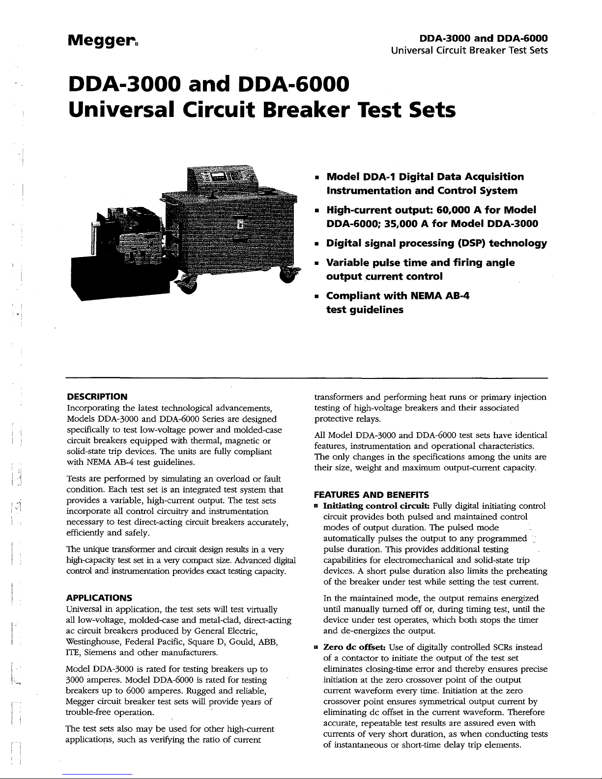
DESCRIPTION
Incorporating
Models
specifically
circuit breakers
solid-state trip devices.
NEMA
with
Tests are
condition. Each test
[
provides a variable, high-current output. The test sets
incorporate all control circuitry
necessary
efficiently
The unique transformer
high-capacity test set in a very compact size. Advanced
control
APPLICATIONS
Universal
all low-voltage, molded-case
ac circuit breakers
Westinghouse, Federal Pacific, Square D, Gould,
ITE,
Siemens
Model
DDA-3000 is rated for testing breakers
3000 amperes. Model DDA-6000
breakers
Megger circuit
trouble-free operation.
The test sets also
applications,
the
latest technological advancements,
DDA-3000
performed
to
and
and
instrumentation provides exact testing capacity.
in
up
and
DDA-6000 Series are designed
to
test low-voltage
equipped
AB-4 test guidelines.
by
set
test direct-acting circuit breakers accurately,
safely.
and
application,
produced
and
other
to 6000 amperes. Rugged
breaker
such
test sets will provide years
may
be
as verifying
power
and
molded-case
with thermal, magnetic
The
units are fully compliant
simulating
is
an
the
manufacturers.
used
an
overload
integrated test system that
and
instrumentation
circuit design results in a very
test sets will test virtually
and
metal-clad, direct-acting
by
General Electric,
is
rated for testing
and
reliable,
for other high-current
the
ratio
of
current
up
or
ABB,
to
or
fault
digital
of
transformers
testing
protective relays.
All
Model DDA-3000
features, instrumentation
The
only changes
their size, weight
FEATURES
III Initiating
circuit provides
modes
automatically pulses
pulse duration. This provides additional testing
capabilities for electromechanical
devices. A short pulse duration also limits
of
the
In
the
until manually
device
and
II
Zero
of
a contactor
eliminates closing-time error
initiation at
current waveform every time. Initiation at
crossover
eliminating
accurate, repeatable test results
currents
of
instantaneous
and
performing
of
high-voltage breakers
and
in
the specifications
and
AND
BENEFITS
control
of
output
breaker
maintained mode,
under
de-energizes the output.
de
offset:
point
dc
of
very short duration, as
circuit: Fully digital initiating control
both
duration.
under
turned
test operates,
Use
to
initiate
the
zero crossover
ensures symmetrical
offset in
or
heat
DDA-6000 test sets have identical
and
maximum output-current capacity.
pulsed
The
the
output
test while setting
the
off or, during timing test, until the
of
digitally controlled
the
the
short-time delay trip elements.
runs
or
primary injection
and
their associated
operational characteristics.
among
and
maintained control
pulsed
mode
to
any
programmed
and
solid-state trip
the
output
remains energized
which
both
stops
output
of
the
and
thereby
point
of
the
output
current waveform. Therefore
are
assured
when
conducting tests
the
units are
the
preheating
test current.
the
timer
SCRs
instead
test
set
ensures precise
output
the
zero
current
even
by
with
Page 5
Meggerm
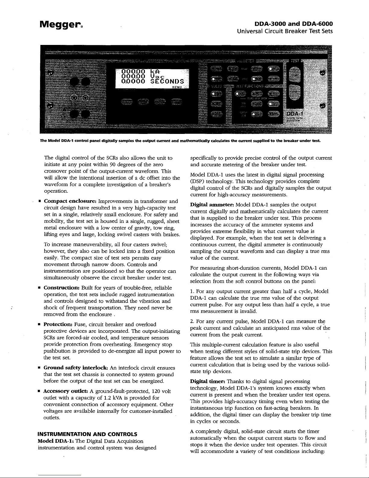
The
Model
DDA-1 control
panel
digitally
s.amples
the
output
current
and
mathematically
calculates
DDA-3000
and
DDA-6000
Universal Circuit Breaker Test
the
current supplied
to
the
breaker
under
Sets
test.
The digital control
initiate at
crossover
will allow
any
point
the
waveform for a complete investigation
of
the
SCRs
also allows the unit
point
within 90 degrees
of
the
output-current waveform. This
intentional insertion
of
the zero
of
a dc offset into
of
a breaker's
operation.
•
Compact
enclosure:
Improvements
in
transformer
circuit design have resulted in a very high-capacity test
set
in
a single, relatively small enclosure. For safety
mobility,
metal enclosure with a
lifting eyes
the
test
set
is
housed
low
and
large, locking swivel casters with brakes.
in a single, rugged,
center
of
gravity,
tow
ring,
To increase maneuverability, all four casters swivel;
they
also
can
be
however,
easily. The
movement
compact
through
locked into a fixed pOSition
size
of
test sets permits easy
narrow doors. Controls
and
instrumentation are positioned so that the operator
Simultaneously observe
•
Construction:
operation,
Built for years
the
test sets include rugged instrumentation
and controls designed to withstand
shock
of
frequent transportation. They
removed from
the
• Protection: Fuse, circuit breaker
the
circuit breaker
enclosure .
under
of
trouble-free, reliable
the
vibration
need
never
and
overload
test.
and
protective devices are incorporated. The output-initiating
SCRs
are forced-air cooled,
provide protection from overheating. Emergency
pushbutton is
provided
and
temperature sensors
to de-energize all
input
stop
power
the test set.
•
Ground
that
before
•
Accessory
outlet with a capacity
convenient
safety
the
test
the
set
chassis
output
interlock:
of
An
interlock circuit ensures
is
connected to system
the
test
set
can
be
outlet: A ground-fault-protected, 120 volt
of
1.2
kVA
is
proVided for
connection
of
accessory equipment.
ground
energized.
Other
voltages are available internally for customer-installed
outlets.
INSTRUMENTATION
Model
DDA-l:
instrumentation
AND
CONTROLS
The
Digital Data Acquisition
and
control system was deSigned
to
the
and
and
sheet
can
be
specifically
and
to
provide precise control
accurate metering
of
the
breaker
of
the
under
Model DDA-1 uses the latest in digital signal processing
(DSP) technology. This technology provides complete
digital control
of
the
SCRs
and
digitally samples
current for high-accuracy measurements.
Digital
current digitally
that is supplied to
increases
provides extreme flexibility in
displayed. For example,
continuous current, the digital
sampling
value
ammeter:
the
the
of
the
current.
Model DDA-1 samples
and
mathematically calculates
the
breaker
accuracy
of
the
ammeter systems
when
output
waveform
under
test. This process
what
current value is
the
test
set
ammeter
and
can
the
is
is continuously
display a true rms
For measuring short-duration currents, Model DDA-1 can
calculate
selection from the soft control buttons
1.
DDA-1
current pulse. For any
rms measurement
2.
peak
current from
For any
can
For
any
current
the
output
output
current in
current greater
the
than
calculate the true rms value
output
less
is
invalid.
current pulse, Model DDA-1
and
the
calculate
peak
an
current.
anticipated rms value
following ways via
on
the
half a cycle, Model
of
the
than
half a cycle, a true
can
This multiple-current calculation feature is also useful
to
when
testing different styles
of
solid-state trip devices. This
feature allows the test set to simulate a similar type
current calculation that is being
used
by
the
state trip devices.
Digital
technology, Model DDA-1's system
current is
This provides high-accuracy timing
instantaneous trip function
addition,
in
timer: Thanks to digital signal processing
knows
present
and
when
the
breaker
even
on
fast-acting breakers.
the
cycles
digital timer
or
seconds.
can
display
the
exactly
under
when
breaker
A completely digital, solid-state circuit starts
automatically
stops it
will accommodate a variety
when
when
the
the
device
output
current starts to flow
under
test operates. This circuit
of
test conditions including:
output
current
test.
the
output
output
the
current
and
delivering a
panel:
output
measure
th~
of
of
various solid-
when
test opens.
testing the
In
trip time
the
timer
and
the
Page 6
I 1
I i
Megger"
The
DDA
Series
offers
capacity
in a single,
compad
enclosure
easily
maneuvered.
.1.
When
testing a circuit breaker
or
a device
auxiliary contact to monitor (e.g., a single-pole circuit
the
breaker),
flow
and
2.
When
contacts,
flow
and
3.
When
contacts,
flow
and
Digital
the
input
the
test set.
timer starts
stops
when
testing a device
the
timer starts
stops
when
testing a device
the
timer starts
stops
when
voltmeter:
voltage
It
to
also
evaluate contact condition
across
breaker
contacts while subject
when
the
output
and
monitoring normally closed
when
the
contacts
and
monitoring normally
when
the
contacts close.
Model DDA-l
the
test set
can
be
used
by
measuring the voltage
the
output
current is interrupted.
the
output
open.
the
output
can
be
used
or
the
output
as a diagnostic tool
to
high current.
Panel indicators: Panel lamps incorporated for
safety
and
convenience, indicate:
1.
Output
2.
Thermal
3.
GROUND INTERLOCK
4.
OVER
External initiate circuit: Allows initiation
from a
of
WARNING
RANGE
remote
the
set ENERGIZED
or
of
ammeter
location
SHUIDOWN
open
when
desired.
of
SPECIFICATIONS
Input
Because Model DDA-3000/-6000 is
low-voltage circuit breakers, there are a
designed
frequencies.
When
system available.
DDA-3000
Output
Output
zero
the
accommodate
For
to
contend
ordering, select
and
Circuit:
to
the
maximum
device
under
a variety
high
impedance
with
the
the
test set which best suits
The
standard input
DDA-6000 series are as follows:
The
output
current available through
test.
Two
of
load
devices,
used
all over
number
many
different input voltages
power
requirements for
of
the
test set is easily adjustable from
output
ranges are provided
circuit impedances.
the
output
can
be
high
relatively
that
can
which
current starts
current starts
current starts
to
measure
voltage from
operator
the test
the
world
of
test sets
the
power
the
impedance
to
connected
be
has
open
to
drop
set
to
and
in
to
to
test
the
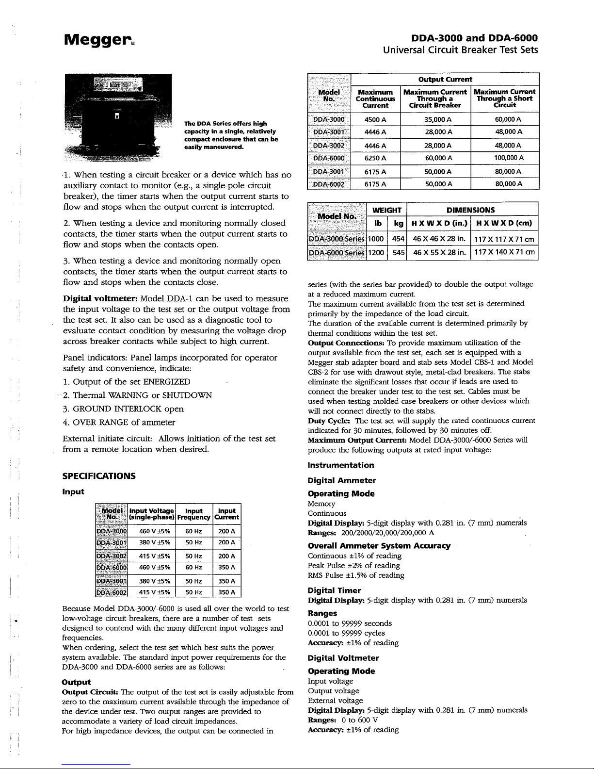
Maximum
Continuous
Current
4500
4446
4446
DOA6000.
no
:ODA-.600:?
6250
6175 A
6175A
to
··;M~d~
PR);;-'3QOOS¢t!¢S1000 454
DDA~600(rs~i,~f
series (with the series
at a
The maximum current available from
primarily
The duration
thermal conditions within
Output
output
Megger stab
CBS-2
eliminate the significant losses that
connect
used
will
Duty
indicated for 30 minutes, followed
Maximum
produce
Instrumentation
Digital
Operating
Memory
Continuous
Digital
Ranges:
Overall
Continuous ±1%
Peak Pulse
RMS
Digital
Digital
Ranges
0.0001
0.0001
Accuracy:
Digital
Operating
Input
Output voltage
External voltage
of
Digital
Ranges: 0 to
Accuracy:
'.-
" .
,,~~
reduced
when
not
Cycle:
Pulse ±1.5%
voltage
.
for
..
~:2··I-W_E_IG,-H_T-+-
'~'''
..•. ',.,
Ib
.'.
-;
Connections:
available from
the
connect directly
the
Ammeter
Display:
Timer
Display:
to
to
Voltmeter
Display:
1200 545 46 X 55 X 28 in. 117 X 140 X
.yo:.:.:':
,,:-,-,.
maximum current.
by
the impedance
of
the available current is determined primarily
adapter
board
use
with drawout style, metal-clad breakers. The stabs
breaker
under
testing molded-case
The
test
Output
Current:
following outputs
Mode
5-digit display
200/2000/20,000/200,000 A
Ammeter
of
reading
±2%
of
reading
of
reading
5-digit display
99999 seconds
99999 cycles
± 1 %
of
reading
Mode
5-digit display
600 V
±
1%
of
reading
DDA-3000
Universal
A
A
A
A
kg
bar
provided)
the
To provide
the
test set,
to
set
will
System
Circuit
Output
Maximum
Through
Circuit
Breaker
35,000
2S,OOOA
2S,OOOA
60,000
50,000
50,000
____
H X W X D
46X46X28in.
to
of
the
load
test set.
maximum
each
and
stab
sets Model
occur
test to
the
breakers
the
stabs.
supply
by
Model DDA-3000/-6000 Series will
at
rated
with
0.281 in.
Accuracy
with
0.281 in.
with
0.281 in. (7
and
Breaker
Current
Current
a
A
A
A
A
D_I_M_E_NTS_I_O_N_S
(in.)
double
the
test
circuit.
utilization
set
is
equipped
if leads are
test set. Cables must
or
other
the
rated continuous current
30 minutes off.
input
voltage:
DDA-6000
Test
Maximum Current
Through a Short
Circuit
60,000 A
48,000
48,000
100,000 A
SO,OOOA
SO,OOOA
___
H X W X D
117X117X71em
the
output
voltage
set
is determined
of
the
with a
CBS-1
and
Model
used
to
be
devices which
C7
mm) numerals
C7
mm) numerals
mm)
numerals
Sets
A
A
--I
(em)
71
em
by
Page 7
Megger"
DDA-3000
and
DDA-6000
Universal Circuit Breaker
Test
Sets
OPTIONAL
Protective
A
tough
nylon
other
It conforms to
and
oil
exposure
to
(-40
with
fungal
Input
If
the
or
if
use
of
input
ACCESSORIES
Cover
cover
made
of
is available for protecting the test
particulate matter during storage.
Mil-C-43006D
hydrocarbon resistance.
to
temperatures ranging from -40
+820
C),
and
Autotransformer
nominal input voltage for the test set is
at
different locations requires the
voltages,
heavyweight, reinforced, vinyl-coated
and
and
the fire-retardant material is treated
ultraviolet ray inhibitors.
an
autotransformer may
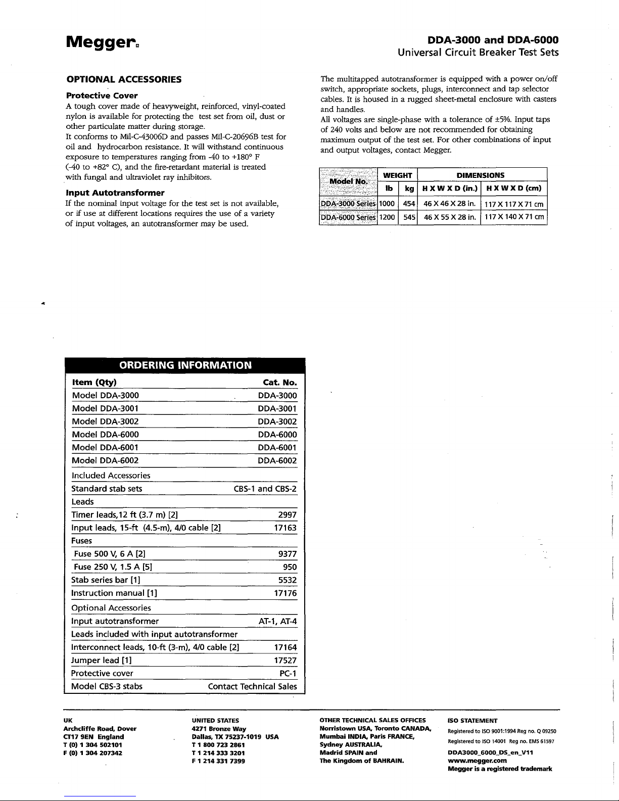
ORDERING
Item
(Qty)
Model
DDA-3000 DDA-3000
Model
DDA-3001 DDA-3001
Model
DDA-3002 DDA-3002
Model
DDA-6000 DDA-6000
Model
DDA-6001 DDA-6001
Model
DDA-6002 DDA-6002
Included Accessories
Standard stab sets
Leads
Timer
leads, 12
Input
leads,
Fuses
Fuse
500
Fuse
250
Stab series
Instruction manual [1]
Optional
Input
autotransformer
Leads included
Interconnect
Jumper
Protective cover
Model
15-ft
V,
6 A [2]
V,
1.5 A [5]
bar
Accessories
leads,
lead [1]
CBS-3
stabs
ft
(3.7 m) [2] 2997
(4.5-m), 4/0 cable [2] 17163
[1]
with
input
autotransformer
10-ft
(3-m), 4/0 cable [2]
set
from oil,
dust
passes Mil-C-20696B test for
It
will withstand continuous
to
+ 1800 F
not
available,
use
of
a variety
be
used.
INFORMATION
Cat.
CBS-1
and
AT-1,
Contact Technical
or
No.
CBS-2
9377
950
5532
17176
AT-4
17164
17527
PC-1
Sales
The multitapped autotransformer is
switch, appropriate sockets, plugs, interconnect
cables.
It
is
housed
in a rugged sheet-metal enclosure with casters
and
handles.
All
voltages are single-phase with a tolerance
of
240 volts
maximum output
and
::.+'~fl;~.!.;'"
PQ~~3,~9(t~~fjeS.1000
D().I(6aOQS~ri~S
and
below
are
of
the test set.
output voltages, contact Megger.
7.,EIG::
454
1200 545
equipped
not
recommended
For
H X W X
46 X 46 X 28
46
X 55 X 28
with a
power
on/off
and
tap selector
of
±5%.
Input taps
for obtaining
other
combinations
:~:~NS~O:~
in.
117 X 117 X
in.
117 X 140 X
of
X D
(em)
71
71
input
em
em
UK
Archcliffe
CT17
9EN
T (0) 1
F
(0) 1 304
304
Road,
England
502101
207342
Dover
UNITED
4271
Dallas,
T 1
800
T 1
214
F 1
214
STATES
Bronze
TX
723
333
331
Way
75237-1019
2861
3201
7399
U5A
OTHER
TECHNICAL SALES OFFICES
Norristown
Mumbai
Sydney
Madrid
The
INDIA,
AUSTRALIA,
5PAIN
Kingdom
U5A,
and
of
Paris
BAHRAIN.
Toronto
FRANCE,
CANADA,
ISO STATEMENT
Registered
to
ISO
9001:1994 Reg no. Q 09250
Registered
to
ISO
14001
Reg
no.
DDA3000_6000_DS_en_ V11
www.megger.com
Megger
is a registered
trademark
EMS
61597
Page 8
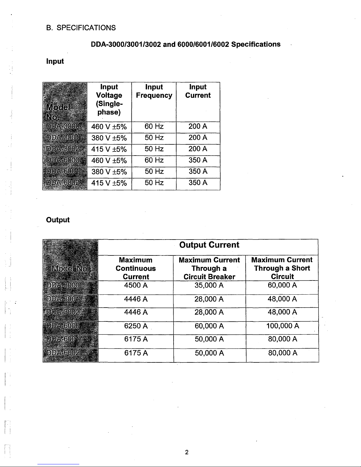
B.
SPECIFICATIONS
DDA-3000/3001/3002 and 6000/6001/6002 Specifications
Input
Input Input Input
Voltage
Frequency Current
(Single-
phase)
Output
460V±5%
380V±5%
415V±5%
460V±5%
380V±5%
415V±5%
Maximum Maximum Current
Continuous Through a
60 Hz
50 Hz 200 A
50 Hz
60 Hz
50 Hz
50
Current
4500 A
Hz
200A
200 A
350 A
350A
350 A
Output Current
Circuit Breaker
35,000 A
Maximum Current
Through a
Short
Circuit
60,000 A
I'
\
f
~
!
I
I
4446 A
4446 A
28,000 A
28,000 A
6250 A 60,000 A
6175A
6175A
50,000 A
50,000 A
2
48,000 A
48,000 A
100,000 A
80,000 A
80,000 A
Page 9
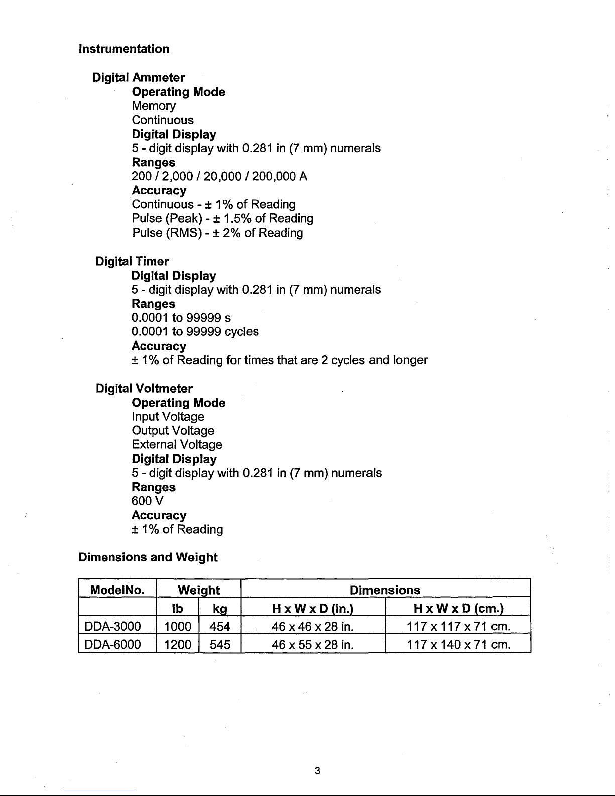
Instrumentation
Digital
Ammeter
Operating Mode
Memory
Continuous
Digital Display
5 - digit display with 0.281
Ranges
200/2,000/20,000/200,000
Accuracy
Continuous - ± 1 %
Pulse (Peak) - ± 1.5%
Pulse (RMS) - ± 2%
Digital Timer
Digital Display
5 - digit display with 0.281
Ranges
0.0001 to 99999 s
0.0001 to 99999 cycles
Accuracy
± 1 %
in
(7
mm) numerals
A
of
Reading
of
Reading
of
Reading
in
(7
mm) numerals
of
Reading for times that are 2 cycles and longer
Digital Voltmeter
Operating Mode
Input Voltage
Output Voltage
External Voltage
Digital Display
5 - digit display with 0.281
Ranges
600 V
Accuracy
± 1 %
of
Reading
Dimensions and Weight
ModelNo.
Weight Dimensions
Ib kg H x W x D (in.)
DDA-3000 1000
DDA-6000
1200
454 46 x 46 x 28 in.
545
---
-
in
(7 mm) numerals
46 x 55 x 28 in.
--~
-
xWx
H
117 x 117 x
------
-
117 x
D (em.)
140 x
71
71
cm.
cm.
3
Page 10
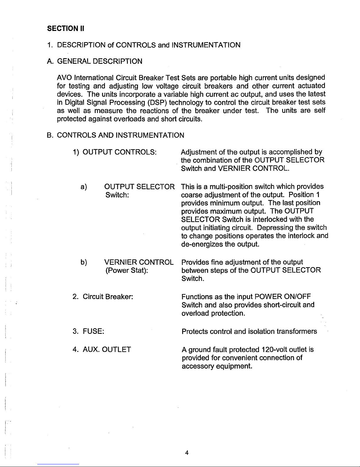
SECTION II
1.
DESCRIPTION
A.
GENERAL DESCRIPTION
of
CONTROLS and INSTRUMENTATION
AVO International
Circuit Breaker Test Sets are portable high current units designed
for testing and adjusting low voltage circuit breakers and other current actuated
ac
devices. The units incorporate a variable high current
in
Digital Signal Processing (DSP) technology
well as measure the reactions
as
of
the breaker under test. The units are self
to
control the circuit breaker test sets
output, and uses the latest
protected against overloads and short circuits.
B.
CONTROLS AND INSTRUMENTATION
1) OUTPUT CONTROLS:
a) OUTPUT SELECTOR
Switch:
Adjustment
the combination
Switch
This is a multi-position switch which provides
coarse adjustment
of
the output is accomplished by
of
the OUTPUT SELECTOR
and VERNIER CONTROL.
of
the output. Position 1
provides minimum output. The last position
provides maximum output. The
SELECTOR Switch
is interlocked with the
OUTPUT
output initiating circuit. Depressing the switch
to change positions operates the interlock and
de-energizes the output.
I .
I
b)
VERNIER
(Power
2. Circuit Breaker:
3.
FUSE:
4. AUX.
OUTLET
CONTROL Provides fine adjustment
Stat): between steps
of
the OUTPUT SELECTOR
Switch.
Functions
Switch
as
the input
and also provides short-circuit and
overload protection.
Protects control and isolation transformers
A ground fault protected
for
provided
convenient connection
accessory equipment.
of
the output
POWER
ON/OFF
120-volt outlet is
of
4
Page 11

5.
Input Receptacles
6.
Equipment Ground
7.
Isolation Ground
Receptacles for input power connection
Test set chassis ground. For safety purposes,
this should be connected to a power system
ground.
is
part
of
an
This ground connection
circuit that verifies that the test set chassis
interlock
is
connected to a separate earth ground.
5
Page 12
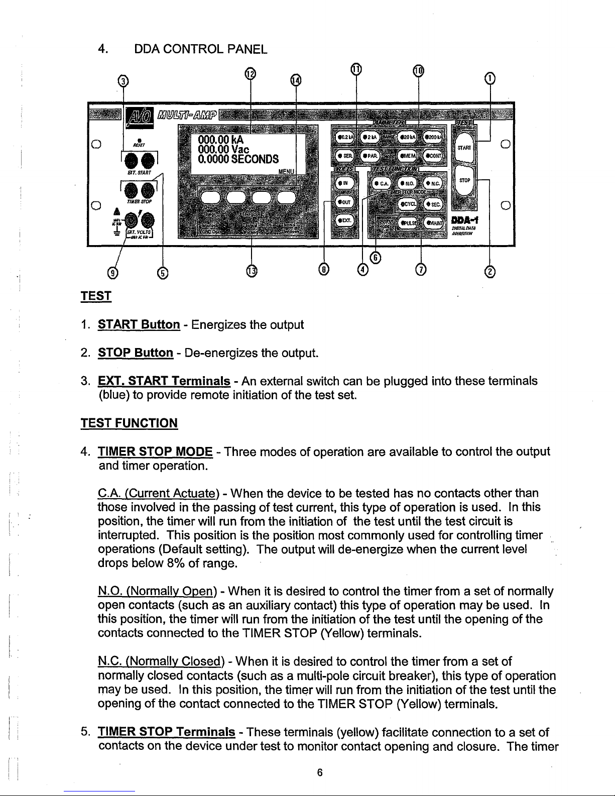
4. DDA CONTROL PANEL
o
TEST
1.
START
Button
- Energizes the output
i
I
I
2.
STOP
3.
EXT. START
(blue) to provide remote initiation
TEST FUNCTION
4. TIMER STOP MODE - Three modes
and timer operation.
C.A. (Current Actuate) - When the device
those involved
position, the timer will run from the initiation
interrupted. This position is the position most commonly used for controlling timer
operations (Default setting). The output will de-energize when the current level
drops below 8%
N.O. (Normally Open) - When it is desired to control the timer from a set
open contacts (such as an auxiliary contact) this type
this position, the timer will run from the initiation
contacts connected to the
Button
- De-energizes the output.
Terminals
in
the passing
of
range.
- An external switch can be plugged into these terminals
of
the test set.
of
of
test current, this type
TIMER STOP (Yellow) terminals.
operation are available to control the output
to
be tested has no contacts other than
of
operation is used. In this
of
the test until the test circuit is
of
of
operation may be used.
of
the test until the opening
normally
In
of
the
I
I
I
, !
N.C. (Normally Closed) - When it is desired to control the timer from a set
normally closed contacts (such as a multi-pole circuit breaker), this type
may be used.
opening
5.
TIMER STOP
contacts on the device under test to monitor contact opening and closure. The timer
of
In this position, the
the contact connected to the TIMER STOP (Yellow) terminals.
Terminals
of
of
operation
tim~r
- These terminals (yellow) facilitate connection to a set
will
6
run
from the initiation
of
the test until the
of
Page 13
stops and output is de-energized when the device operates (used
with the
6.
TIME UNITS Selection- Selects the mode
7.
OUTPUT Mode - The following two selections are available
TIMER STOP MODES
PULSE - When selected, the output
period (default is 5 cycles) and then
of
N.O. and N.C).
of
of
the test set is on for a short, specified time
is
turned off. (Should the device under test
count; either cycles
in
conjunction
or
seconds.
operate after pushing the START Button, the output will be de-energized). This
position is
normally used when setting the test current prior to the timing test and
providing short high current pulses for instantaneous tests. However, the duration
this output pulse can be programmed via the Display Menu. (See the Section III,
Front Panel Display and Programming Menus.) (Default Setting).
MAl NT. - When selected, and the START Button is pressed, the control circuit
of
maintains the output
the test set until the device under test operates or the STOP
Button is pressed. This is the normal position for Time Delay tests.
VOLTS (voltmeter selection) Switches
of
E.
8.
VOLTS - three different selections are available for display
IN
- When this voltage display selection is made, the voltage at the input plugs
test set will be displayed (Default Setting).
OUT - When this voltage display selection is made, the voltage at the output
of
terminals
the test set will be displayed.
EXT. - When this voltage display selection is made, the voltage applied to the EXT.
VOLTS terminals will be displayed.
9.
EXT. VOLTS terminals - These two terminals enable the digital voltmeter to
measure external a.c. voltages up to
AMMETER
10. AMMETER RANGE Switches - Selects the desired full scale range
600 Volts.
of
the meter.
NOTE: The output current level from the test set must be at least 8 percent
any full scale value before the ammeter will indicate an output reading. Please be
aware that changing ammeter ranges while the output is energized may
in erroneous ammeter readings. The 4 range selections are
0.2kA1
2kA1
and 200 kA range. Default Setting is the 200 kA range.
of
the
result
20kA I
of
11.AMMETER MODE
MEM/CONT - Selects the mode
highest measured current is indicated on the ammeter.
of
the ammeter circuit. In the MEM position, the
The
CONT mode permits
7
Page 14
the ammeter to continually indicate the value
and MAl NT. Modes
current value will be displayed. Default
of
operation, it will require 30 cycles
Setting is MEM.
of
output current. When
of
output current before a
in
the CONT.
SERIPAR switch must be in the
amount
When
operating the unit with the output in a series configuration, this
SERIES position in order for the ammeter to read the correct
of
output current. (See Section IV, 2, A for more details.) The default setting
is PARALLEL.
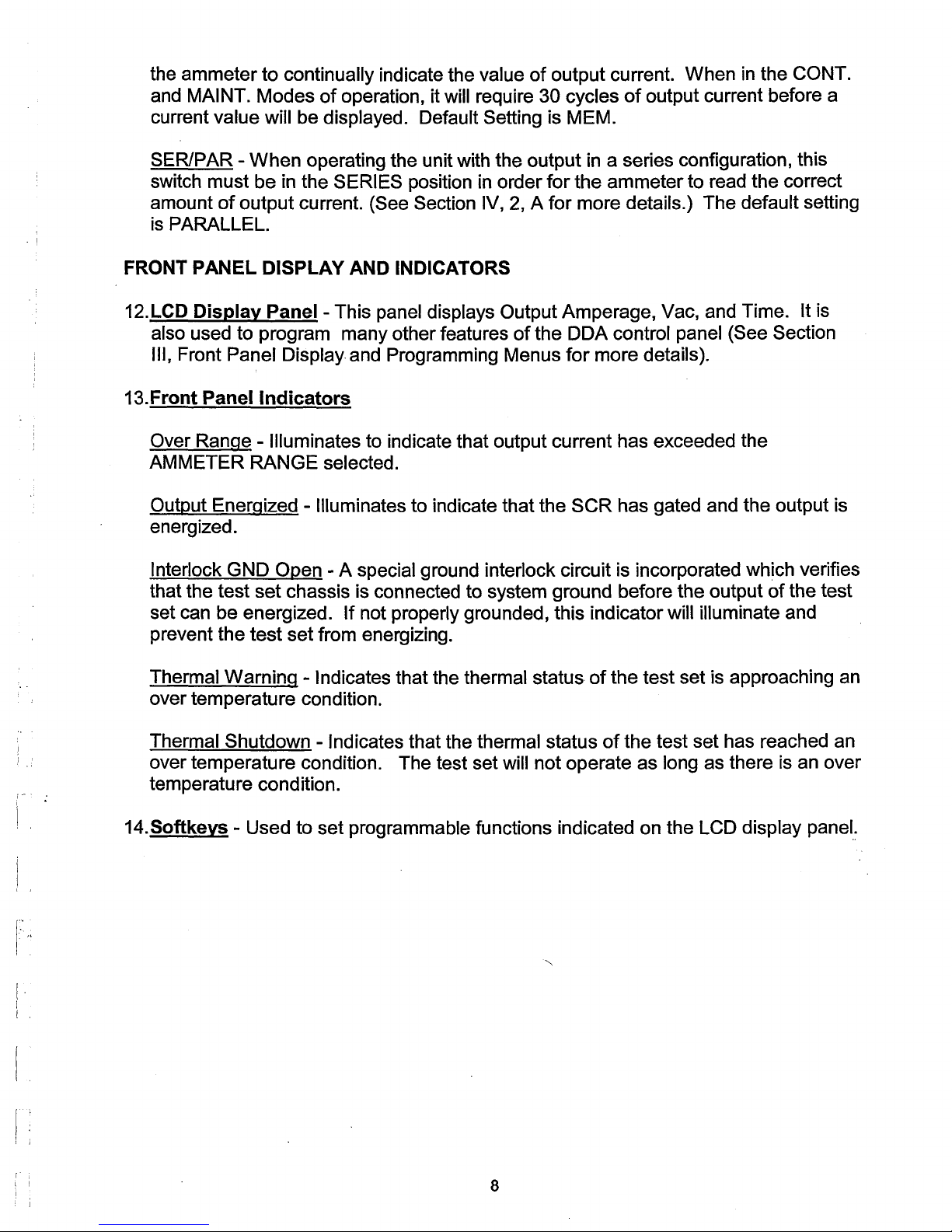
FRONT PANEL DISPLAY AND INDICATORS
12.
LCD Display Panel - This panel displays Output Amperage, Vac, and Time. It is
of
also used to program many other features
Front Panel Display and Programming Menus
III,
13.Front Panel
Over
Range - Illuminates to indicate that output current has exceeded the
Indicators
the DDA control panel (See Section
for
more details).
AMMETER RANGE selected.
Output Energized - Illuminates to indicate that the SCR has gated and the output is
energized.
Interlock GND Open - A special ground interlock circuit is incorporated which verifies
of
that the test set chassis is connected to system ground before the output
set can be energized.
If
not properly grounded, this indicator will illuminate and
the test
prevent the test set from energizing.
I"
[
I
I
.,
Thermal Warning -
Indicates that the thermal status
of
the test set is approaching an
over temperature condition.
Thermal Shutdown -
Indicates that the thermal status
of
the test set has reached an
over temperature condition. The test set will not operate as long as there is an over
temperature condition.
14.Softkeys - Used to set programmable functions indicated on the
LCD display panel:
8
Page 15
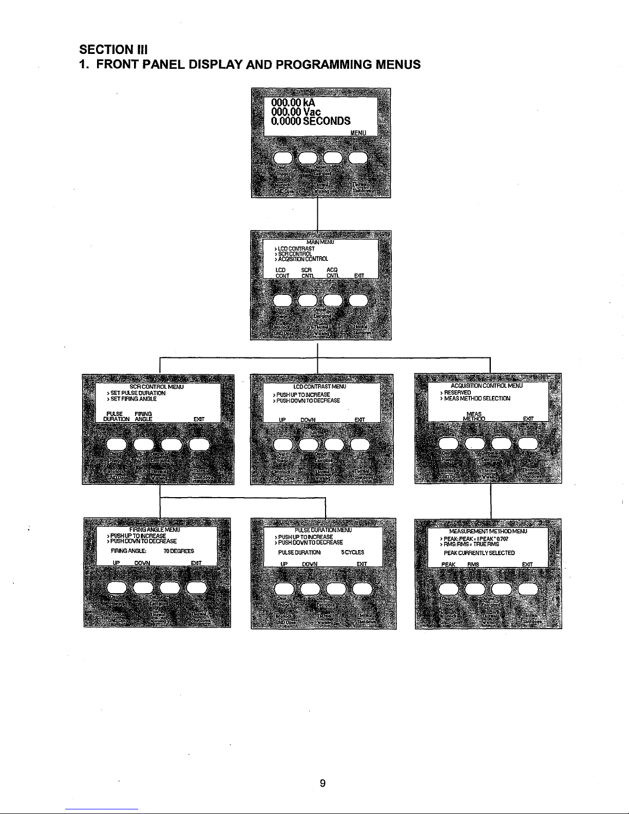
SECTION III
1. FRONT PANEL DISPLAY AND PROGRAMMING MENUS
9
Page 16

2.
Flow
Diagram
of
Display Menus
A. METERING DISPLAY
I
I
All
of
the programmable menu options may be accessed by pressing the soft key
in
underneath the word MENU
following
display will appear.
the metering display screen. When pressed, the
I •
; .
I ' :
I
MAIN MENU
B.
From the
adjustments to the
MAIN MENU the user may select programming menus to make
LCD display contrast, SCR controls,
or
Acquisition control
(current calculation method). The user may also select to EXIT back out to the
metering
key
display screen. The desired option would be selected by pressing the soft
directly beneath that option.
10
Page 17

C. LCD CONTRAST MENU
The LCD
CONTRAST MENU provides two options for optimizing a user's ability to
view the display. Pressing the soft key directly beneath UP will cause the intensity
of
the display to be increased. Pressing the soft key directly beneath DOWN will
of
cause the intensity
the display to be decreased. This menu also provides the
option to return to the previous menu by pressing the soft key directly beneath
D.
SCR CONTROL MENU
EXIT.
SCR CONTROL MENU provides the ability to enter into two different areas
The
SCR adjustment. Pressing the soft key directly beneath PULSE DURATION will
display a menu that will
of
output
key beneath
the test set will be energized during a momentary pulse. Pressing the soft
FIRING ANGLE will display a menu that will allow the user to program
the angle at which the output signal
E.
PULSE DURATION AND FIRING ANGLE MENUS
allow the user to program the number
of
the test set is initially energized.
11
of
cycles that the
of
Page 18

The PULSE DURATION MENU allows the user to program the number
that the output
number
of
beneath UP
of
the test set will be energized during a momentary pulse. The
cycles can be increased
or
DOWN. Pressing the soft key beneath EXIT will return the user to
or
decreased by pressing the soft keys directly
of
cycles
the previous menu. The default pulse duration setting is 5 cycles.
FIRING ANGLE MENU allows the user to program the initial firing angle at
The
which the output signal
of
the test set is energized. This is important when dealing
with asymmetrical waveforms. The more inductive the test specimen, the more
asymmetrical the output
output
of
the test set has become
the test set will be due to DC offset. Asymmetry
of
increased importance when performing
in
the
of
instantaneous trip tests on circuit breakers. By providing the ability to adjust the
firing angle
of
the test set, the user can minimize the effect
of
DC offset and
therefore collect more accurate information with regard to the instantaneous
characteristics
information on how to determine
to adjust the firing angle if it is not. The default firing angle is
F.
ACQUISITION CONTROL MENU
of
the test specimen. See ACQUISITION CONTROL MENU for
if
the output
of
the test set is symmetrical and how
70
0
.
12
Page 19

The Acquisition Control MENU allows the user to select between two different
current measurement methods. By pressing the softkey
or
PEAK
measured current on the metering display. PEAK measures the highest peak and
multiplies it by a constant 0.707. This method
compared to the
which is a true rms measurement.
measurements will be approximately the same current
measurements are not approximately the same
a way as to bring the two measurements
RMS
angle
order
angle. The method
beneath the desired method. Pressing the softkey beneath
to the previous menu. The
RMS, the user selects which calculation will be used in displaying
of
measurement should initially be
RMS measurement method (with all output setting being the same),
If
the output waveform is symmetrical, the two
value, adjust the firing angle
closer together.
measurement
that
will
to
minimize
will
bring
never
these
be
the same value, the
two
measurements
as
DC offset. See FIRING ANGLE MENU
of
current measurement is selected by pressing the soft key
default setting is PEAK.
directly beneath either
value.
close
If
these two
Although
goal
is
together
for
EXIT will return the user
the
to
find
as
adjustment
in
such
PEAK
the
and
firing
possible
of
firing
in
13
Page 20

SECTION IV INPUT AND OUTPUT CIRCUITS
1. INPUT:
A. INPUT VOLTAGE: The AVO International Circuit Breaker Test Sets are designed to
operate on a single phase voltage source.
the nominal rated voltage source
is
not
If
available, or if use at various locations requires the capability to operate the test set
from several different input voltages an optional input autotransformer may be used
in
(see Bulletin
Section I for description) .
. B. INPUT LEADS: The power source must have sufficient capacity to maintain RATED
input voltage at the
foot 2
10
input cables with connectors on one end. This
INPUT terminals
of
the test set. All units are supplied with
is
done in an effort to
15
provide a locking input connector, for safety purposes, along with input cables that
of
are appropriate for a minimal amount
of
input terminals
satisfactorily at 95-105%
input terminals will result
the test set. Although the test sets are designed to operate
of
rated voltage, any drop in voltage below RATED at the
in
a proportional decrease
voltage drop from the input source to the
in
the maximum available
output.
NOTE: To achieve published output currents, the rated input voltage must be
maintained at the test set terminals during the test.
C.
GROUNDING: For safety, ground wires must be connected to the test set chassis
in order to energize the test set.
terminal located just
belowlhe
One ground lead must be connected to the ground
input plug to system ground. The size
of
the
conductor should be not less than 6 AWG. Due to the special ground interlock
circuit, a second lead must be connected from the green GND binding post to a
separate, but compatible system ground. This will insure that a ground has been
achieved and allow the test set to be energized.
D.
SAFETY PRECAUTIONS:
CAUTION
For
safety
of
the operator, it is absolutely essential that the test set be properly and
effectively grounded.
2. OUTPUT:
SELECTION OF OUTPUT CONNECTIONS: Two output connections, parallel
A.
series, provide various voltage and current ratings to adapt AVO International Circuit
Breaker Test
Sets to a wide variety
of
test circuit impedances.
and
The test sets can be operated most effiCiently by utilizing the parallel connection,
which provides the
HIGHEST CURRENT rating consistent with being able to obtain
the desired test current.
of
maximum use
the variable autotransformer range .. Even the smallest currents
can be obtained from the parallel connection. The series connection should be used
only when testing high impedance devices where the parallel connection does not
In
this way, finer adjustment can be obtained by making
14
Page 21

have sufficient voltage to "push" the desired test current through the device. The
operator should start with the
only when necessary. To operate the test set
require any changes be made by the operator. However the test set in series
requires that a special adapter be placed on the output stab adapter boards to
complete the series connection.
parallel connection and move to the series connection
in
the parallel connection does not
See figures below.
I
PARALLEL
NOTE: When the output
used to connect the output
B.
OUTPUT CONNECTIONS: Both models DDA-3000/6000 Test Sets are equipped··
with an AVO International Stab Adapter Board and AVO International CBS-1 and
CBS-2 Stab Sets which accommodate direct engagement
circuit breakers to the test set without the use
available for breakers not accommodated by the
the factory for further details
When testing devices which cannot be connected directly to the stabs
3000/6000 Series Test Sets, it will be necessary to use test leads. When using high
current test leads, it may be necessary to connect the output
(see Section IV, 2, A on PARALLEL AND SERIES OPERATION).
information on the selection
choosing the proper test
I
of
the test set is
of
the test set to the test specimen.
or
refer to the specification section.
of
output leads will provide the
leads for his application.
I
in
a series configuration, cabling must
of
leads. Additionally, stabs are
CBS-1 and CBS-2 stabs. Contact
I
SERIES
of
user
-
many drawout type
of
the DDA-
of
the test set
The
following
with a guide for
in
be
series
Due to the
voltage drop from the inductive reactance
15
of
the test circuit, a significant
Page 22

loss
of
current will result for each inch
leads, the length and size
current.
It is worthwhile to sacrifice cross section
reducing length. Every inch
increase
even though the
is
convenient
in
available test current. Heating is not a Significant problem
leads become hot. The use
for
constructing test leads. Paralleling
higher test currents. Each
bolted to the output terminals or stab board
then
of
leads chosen will determine the maximum available test
of
lead that can be eliminated provides a worthwhile
cable can be fitted with a compression lug on each end,
of
test lead. Therefore, when choosing test
of
test leads for the sake
of
4/0 welding
of
of
the test set and the breaker.
or
motion picture cable
sufficient cables provides
in
testing,
of
The two
bundled with tape
cables between the test set and the breaker should be twisted together or
or
cord to maintain the close proximity which minimizes inductive
reactance.
It
is
sometimes necessary to use bus bar
current. When using bus bar, the buses
one another as
C.
DUTY RATINGS AND OVERLOAD CAPACITIES:
possible.
in
order to obtain the desired maximum
should be run parallel and kept as close to
AVO International equipment is rated on a continuous duty basis as described by
in
NEMA for test equipment
intermittent service; that is, 30 minutes ON followed by
30 minutes OFF. This means that, the equipment can supply rated output current
of
for a maximum period
follows. This is a satisfactory basis
primary injection testing
30 minutes ON provided a 30 minute cooling OFF period
of
rating for testing
of
relay and current transformers. When AVO International
of
circuit breakers and
equipment is being used for heat runs on cables, bussbars, terminations, etc., the
30 minute ON time may be exceeded.
limited to 70 percent
of
the rated output current and may be continued
In
such cases the output current should be
for
an
indefinite time.
In
addition to the continuous duty rating defined above, all units have considerable
short-time overload capability. Duration
considerations within the test set. The maximum current available is determined
essentially
by
the
impedance
series is as follows:
I
I '
r
! I
of
the overload is governed by thermal
of
the load. The duty cycles
16
of
the DDA-3000/6000
Page 23

DUTY
CYCLES ON DDA-3000/6000 SERIES 60 HZ
CIRCUIT
(Current Rating Through Circuit Breaker)
BREAKER TEST SETS
DDA-3000
CURRENT
3,000 A
4,500 A
. 6,000 A
15,000 A
30,000 A
CURRENT
4,500 A
6,250 A
10,000 A
30,000 A
60,000 A
TIME ON
Continuous
30 min . 30 min.
15 min. 45 min.
2 min.
5 sec. 12 min.
DDA-6000
TIME ON
Continuous
30
min.
15 min.
2 min.
5 sec.
THERMAL SET POINTS*
TIME
60 min.
TIME
30 min.
45 min.
60 min.
12 min.
OFF
N/A
OFF
N/A
Normal: 72° to 80°F
Warning: 160 to 190°F
Shutdown:
191
to 240°F
*Temperature measured at output stabs adapter plates.
17
Page 24

DUTY CYCLES ON DDA-3000/6000 SERIES 50 Hz
CIRCUIT BREAKER TEST SETS
(Current Rating Through Circuit Breaker)
DDA-3001/3002
. I
CURRENT
2,964 A
4,446 A
5,928 A
14,820 A
29,640 A
CURRENT
4,446 A
6,175 A
9,880 A
29,640 A
59,280 A
TIME ON
Continuous
30 min.
15 min.
2 min.
5 sec.
DDA-6001/6002
TIME ON
Continuous
30 min.
15
min~
2 min.
5 sec.
THERMAL SET POINTS*
Normal: 22.2 to 26.7°C
TIME OFF
N/A
30 min.
45
min.
60 min.
12 min.
TIME OFF
N/A
30 min.
45
min.
60 min.
12 min.
Warning: 71.1 to 87.8°C
Shutdown: 88.3 to 115.6°C
*Temperature measured at output stab adapter plates.
I
[
I
..
18
Page 25

SECTION V
1. TEST PROCEDURES FOR TESTING OF MOTOR OVERLOAD RELAYS
Always refer to the manufacturer's literature applicable to the particular overload relay
before testing. The test operator should be familiar with the operating characteristics
the relay, the tolerances applicable to the operating characteristics and any means
adjusting the relay.
of
of
The test usually performed on these devices is to verify the time delay characteristics
of
. the relay when subjected to an overload condition. One test point is usually suggested
establish whether the relay
to
for
current curve
current rating
of
magnetic overload relays.
is,
of
It
course, easiest to make the connections and perform the tests on the relays if
the relay. The suggested test current is three times (3x) the normal
of
thermal overload relays
they are removed from the starter. However, it
is
operating correctly and within the band
or
three times (3x) the pick-up current (setting)
is
not necessary to remove the relay
of
the time-
as
long as the power circuit is de-energized and the test leads can be connected to the
device. The high current
as short as
possible and should be twisted to minimize losses caused by inductive
leads from the test set to the relay under test should be kept
reactance.
Run the test and note the time required for the
exceeds the manufacturer's recommended
relay may not be protecting the motor properly.
result in unnecessary nuisance trips.
operate over a wide band and precise
It should be remembered that these devices
results should not be sought. A tolerance
overload relay to trip.
value, or
If
if
the relay does not trip at all, the
th.e
relay operates too quickly, it may
If
the tripping time
of
.±
15% is usually acceptable for electromechanical devices.
If
a thermal overload relay is not operating properly, tripping too soon
or
too late,
remove the heater element. Note its type, rating, etc., and compare with
manufacturer's data
application, substitute a new heater
over-sized heater
for
operating characteristics
of
the same rating and retest.
of
the motor.
If
correct
If
for
the
either under- or
elements are being used, replace with the proper size heater and
retest.
If
a magnetic overload relay is not operating properly, refer to the relay manufacturer's
literature for instructions on making adjustments
operating
operating point)
delay feature
improperly, it also may be desirable to verify the pickup point (minimum
of
the relay. To perform this test, it is necessary to disengage the time
of
the overload relay. Refer to the manufacturer's literature for detailed
instructions.
19
of
the time delay.
If
the relay is
Page 26

TESTING OF TIME DELAY:
-~
I
1. Connect the test set to a
on the test set is
OFF.
suitable source
of
power. Be sure
that
the ON/OFF Switch
2. Make sure the motor circuit is de-energized.
3. Connect the output
tested. (See Section IV, 2, B - SELECTION
-4. Connect a set
circuit contacts
5.
Turn test set's ON/OFF Switch "ON". The Control Panel Display should illuminate.
6. Set up
of
controls before testing:
CONTROL
Circuit Breaker
OUTPUT SELECTOR Switch
of
the test set to the terminal
of
light leads from the terminals marked TIMER
of
the relay being tested.
of
the heater
OF
OUTPUT CONNECTION).
POSITION
ON
1
of
operating coil to
STOP
to the control
be
i
i
I-
,-
I·
VERNIER CONTROL
OUTPUT MODE
TIMER STOP MODE
Ammeter MODE
AMMETER RANGE
VOLTMETER
CIRCUIT Selection
Zero (counterclockwise)
PULSE
N.O.
or
N.C... Selection that
is
most appropriate for the TIMER
STOP
Contacts being used.
MEMORY. Also set to Parallel or
Series depending on output
configuration.
So that test current can be read
of
in the proper range
the
ammeter
As desired, depending on
voltage
to be measured
I
,
I
, 1
20
Page 27

7.
Set the desired test current by rotation
pressing the
START button per the following procedure.
of
the VERNIER CONTROL, and then
NOTE: Depending on the position
may be increased by either
CONTROL
current
SELECTOR Switch
(refer to chart
is
7500 amperes, the proper procedure would be to start with the OUTPUT
in
toward "100". However,
clockwise or counter clockwise rotation
of
OUTPUT RANGES). For example,
position 1 and increase the VERNIER CONTROL from "0"
if
the impedance
of
the OUTPUT SELECTOR Switch, the current
of
the VERNIER
if
the desired test
of
the device is such that you cannot get
7500 amperes at "100" on the VERNIER CONTROL with the tap selector on position
"1", switch the OUTPUT SELECTOR Switch to position number 2. On TAP position
#2 the red
CONTROL
scaling is used to increase the output current. Rotate the VERNIER
counterclockwise toward "red 1 00".
If
at full rotation
of
the VERNI
ER
CONTROL, the desired current is not obtained, turn the OUTPUT SELECTOR
Switch
current is reached.
only stay energized for programmed number
PULSE DURATION
amperage set. Continue
the desired test current is not reached, connect the output
to the next higher position and repeat the procedure until the desired test
Since the PULSE OUTPUT MODE is selected, the output will
of
cycles (Default is 5 cycles. See
MENU). The ammeter display will hold the reading
until the desired current is achieved.
If
at the last position
of
the test set
of
in
the
series
(See SELECTION OF OUTPUT CONNECTION, Section IV, 2, A.). Switch the
Ammeter
PARALLEL/SERIES Switch to the SERIES position, return the OUTPUT
SELECTOR Switch to position 1 and repeat the above procedure until the desired
current is achieved.
8.
Select the MAINTAINED OUTPUT
MODE.
9. Select the CONTINUOUS AMMETER MODE.
10.
Wait several minutes to allow the overload relay to cool
or
the
plunger to settle
in
dash pot.
11.lnitiate current by pressing START button. The timer will stop and the output will
automatically de-energize when the overload relay operates.
NOTE: Check the ammeter reading during the test
adjustments may be made with the OUTPUT
CONTROL while the test is
for
accuracy. Minor
in
progress.
12. Record the
results and compare them to the manufacturer's specifications.
the
21
Page 28

2. TEST PROCEDURE
POWER CIRCUIT BREAKERS
FOR
TESTING OF MOLDED CASE AND
LOW
VOLTAGE
Always refer to the manufacturer's literature applicable to the particular circuit breaker
before testing. The test operator should be familiar with the operating characteristics
the circuit breaker, the tolerances applicable to the operating characteristics and any
means for adjusting the circuit breakers.
of
Molded case breakers are usually tested for verification
and the minimum operating point (pick-up point)
of
of
the time delay characteristics
the instantaneous element. Low
. voltage power circuit breakers with solid state or electro-mechanical trip devices are
of
usually tested for verification
the time delay characteristics
short time delay elements and for the minimum operating point (pick-up point)
instantaneous element. Each circuit breaker pole should be tested independently
of
the long time delay and
of
the
so
that all trip devices are tested.
One test point is usually sufficient to establish whether the long time delay or short time
delay element is operating properly and within the band width
characteristics. For molded case breakers the suggested test current
element is three times (3x) the current rating
of
the breaker;
circuit breakers, suggested test current is three times (3x) the pick-up setting
of
its time-current
for
low
voltage power
of
the time delay
of
the long
time delay element and one and one half times (1.5x) the short time delay setting where
of
the type
trip characteristics is incorporated on the trip device.
On both molded case and low voltage power breakers, the instantaneous element is
tested to verify the minimum current necessary to cause the breaker to consistently trip
instantaneously.
When testing instantaneous trip elements, run the test below to find the minimum
current required to trip the breaker instantaneously and compare to the setting.
Remember the instantaneous elements have an operating tolerance
25%
of
setting, depending on the particular trip device. On molded case circuit
of
from
.±
10% to
breakers, it is suggested that the time delay elements be tested before any
instantaneous tests are performed.
.±
Most modern low voltage power circuit breakers are
breakers should be tested using
with the appropriate stabs to directly connect the breaker to the test set. When testing
molded case breakers
or
the test set, the leads should be as short as possible and twisted to minimize losses.
See section on Output Leads.
I
i .
!
I
~
I i
of
the "draw-out" type. These
AVO International Model DDA-3000/6000 equipped
any other breaker where leads are required to connect it to
22
.
Page 29

TESTING OF TIME DELAY:
1. Connect the test set to a suitable source
on the test set is
2. Make sure the line side circuit
disconnected.
OFF.
of
the breaker to be tested is de-energized or
Close the breaker to
3. Connect the test set output terminals to one pole
SELECTION OF OUTPUT CONNECTION
4.
If
the N.O.
from the
desired auxiliary contact.
5.
Turn test set ON/OFF circuit breaker ON. The Control Panel Display should
illuminate.
6. Set up
CONTROL
Circuit Breaker
or
N.C. TIMER STOP MODEs are to be used, connect a set
TIMER STOP terminals to another pole
of
controls before testing:
of
be
tested.
POSITION
ON
power. Be sure that the ON/OFF Switch
of
the breaker to be tested. (See
Section IV, 2, A.)
of
the breaker under test or the
of
light leads
OUTPUT SELECTOR Switch
VERNIER CONTROL
OUTPUT MODE
TIMER STOP MODE
Ammeter MODE
AMMETER RANGE
VOLTMETER
Selection
CIRCUIT
1
Zero (counterclockwise)
PULSE
If
desired, the N.O.
be used to control timer operation.
Otherwise use the
selection.
MEMORY and PARALLEL.
Select a range such that the test current
can be read as near
As desired, depending on voltage to be
measured
or
N.C. selections may
C.A. (Current Actuate)
full scale as possible.
7. Verify proper ammeter range.
Set the desired test current by rotation
8.
pressing the
START button per the following procedure.
of
the VERNIER CONTROL, and then
23
Page 30

NOTE: Depending on the position
current may be increased by either
VERNIER CONTROL (refer to chart
desired test current is
OUTPUT SELECTOR Switch
the
CONTROL
from "0" toward "100". However,
that you cannot get
Selector on position #1, switch the OUTPUT SELECTOR Switch to position
TAP
2.
number
Rotate the
On TAP Position #2 the
VERNIER CONTROL counterclockwise toward "0". If at full rotation
7500 amperes, the proper procedure would be to start with
in
7500 amperes at "100" on the VERNIER CONTROL with the
the VERNIER CONTROL, the desired current
SELECTOR Switch
desired test current is reached.
output will
only stay energized for programmed number
to the next higher position and repeat the procedure until the
Since the PULSE OUTPUT MODE
of
the OUTPUT SELECTOR Switch, the
clockwise or counter clockwise rotation
of
OUTPUT RANGES). For example, if the
position 1 and increase the VERNIER
if
red
scale
the impedance
is
used to increase the output current.
is
not obtained, turn the OUTPUT
of
of
the device is such
is
selected, the
cycles (Default
is
of
5
the
of
cycles. See PULSE DURATION MENU). The ammeter display will hold the reading
of
the amperage set.
connect the output
CONNECTION, Section IV,
If
at the last position the desired test current
of
the test set
in
series (See SELECTION OF OUTPUT
2,
A). Switch the Ammeter PARALLEL/SERIES Switch
is
not reached,
to the SERIES position; return the OUTPUT SELECTOR Switch to position 1 and
repeat the above procedure
until the desired current is achieved.
9.
Select the MAINTAINED OUTPUT
MODE.
10.Select the CONTINUOUS AMMETER MODE.
11.1nitiate unit by pressing START button. The timer will stop and output will
automatically de-energize when the circuit breaker operates.
NOTE: Check the ammeter reading during the test for any change in output
setting. Minor adjustments may be made with the output
control while the test is in
progress.
12.Record the
results and compare them to the manufacture's specifications.
I
I '
24
Page 31

TESTING OF INSTANTANEOUS PICK-UP:
1.
Connect the test set to a suitable source
on
the test set is OFF.
2.
Make sure the line side circuit
disconnected.
3.
Connect the output
Close the breaker to
of
the test set to one pole
of
the breaker to be tested is de-energized or
be
of
power. Be sure that the ON/OFF Switch
tested.
of
the breaker to be tested (see
SELECTION OF OUTPUT CONNECTION, Section IV, 2, B).
4.
Connect a set
pole
of
the breaker being tested. .
of
light leads from the binding post marked TIMER STOP to another
NOTE:
Not applicable when testing single-pole breakers using the C.A. TIMER
STOP MODE.
5.
Turn test set circuit breaker ON. The front panel display should illuminate.
NOTE: To set up controls, see "SETUP OF CONTROLS" before testing
previous section.
6.
Select the proper ammeter range so that the instantaneous pick-up current
of
instantaneous element can be read as near to full scale as possible.
7.
Place the ammeter mode switch
in
the MEMORY. (See Section
111,2,
E to program
pulse duration.)
8.
Rotate VERNIER CONTROL while alternately pressing the START button until the
of
circuit breaker under test trips instantaneously. Read ammeter for value
current
required to trip breaker.
If
breaker does not trip instantaneously with VERNIER CONTROL fully rotated, turn
OUTPUT SELECTOR Switch to next higher position and repeat procedure (refer to
procedure
NOTE under TESTING OF TIME DELAY
in
the previous section).
in
the
the
If
at the last position the required test current still is not reached, connect the test
set's output in series.
2,
B). Switch the AMMETER MODE selection from PARALLEL to SERIES position
and repeat the procedure.
(See SELECTION OF OUTPUT CONNECTION, Section IV,
25
Page 32

3. MAINTENANCE OF PROTECTIVE APPARATUS MAINTENANCE OF MOTOR
OVERLOAD
APPLICATION:
RELAYS
The primary function
too long a period
of
the motor overload relay is to prevent operation
of
time to prevent damage to that motor when an overload condition
of
a motor for
exists.
In
general, motor starters are applicable to a given horsepower range
. voltage and current requirements
of
the application will "size" the starter under NEMA
of
motors. The
requirements, but the actual starting current, running current, ambient temperature and
of
severity
atmospheric conditions will determine the overload relay rating required to
protect the motor without nuisance tripping.
of
Selection
to tables
the properly rated overload relay heater or coil can be made by reference
or
charts supplied by the manufacturer
of
the overload relays. Whenever a
motor trips out it is poor practice to indiscriminately install a larger heater or coil, since
or
the motor may actually be working under an overload condition
or
may be operating improperly. Installing a larger heater
coil could allow an
overloaded motor to continue to run, resulting in deterioration
of
and reduction
of
the trip before changing the rating
characteristics
motor life. Therefore, careful analysis should be made as to the cause
of
the overload relay heater. Operating
of
the motor overload relay should be verified at regular intervals. The
inspection and test interval can vary widely depending on the type
of
the importance
the motor to process or production, and environmental conditions.
the overload relay
of
the motor insulation
of
service involved,
I:·
I .
)
I
I
TYPES:
Motor overload relays incorporate an element which actuates a set
connected to the motor control circuit. These contacts open the circuit
coil
in
the motor starter and interrupt the power to the motor.
In
general, there are three types
1.
Thermal - melting alloy or solder pot
2.
Thermal - bimetallic strip
3.
Electromagnetic
In
thermal type relays, time-current characteristics are obtained by the thermal
of
the
properties
plunger
or
moving iron device is used to produce time delays.
melting alloy
of
motor overload relays in use:
or
bimetallic strip. In the magnetic type, a damped
of
contacts
of
the holding
1. Thermal - melting alloy or solder pot:
In this type, tripping is the result
passing through a "heater"
brass shaft which is surrounded by solder. Fixed to one end
of
heat generated by the motor overload current
in
the overload relay. This overload relay consists
of
the shaft is a small
of
a
ratchet wheel. As long as the solder is solid, this assembly is immobile. When the
i.
motor control circuit contacts are closed, a spring in the motor overload relay is held
26
Page 33

compressed by the immobility
motor increases the current through the heater, thus melting the solder
ratchet wheel to move, and releasing the energy
of
circuit
the holding coil
in
of
the ratchet wheel. An overload condition
in
the spring. This interrupts the
the motor starter and shuts down the motor.
in
the
allowing the
The starter may be reset only after the heater has cooled sufficiently to permit the
solder to solidify and again make the ratchet and shaft immobile. Reset is usually
accomplished by an external pushbutton on the face
overload relays offer a selection
of
either manual
of
the starter. Many motor
or
automatic reset.
·2. Thermal -
This type uses a bimetallic strip---two pieces
An increase in heat will cause movement
set
of
Bimetallic
strip:
of
dissimilar metal bonded together.
of
the bimetallic unit and eventually open a
contacts in the motor control, thus opening the holding coil circuit and shutting
down the motor.
The principle
of
operation is the same as the melting alloy type. When the bimetallic
element has cooled sufficiently, the motor control circuit may be reset either
manually
3.
Electromagnetic:
In this type
or
automatically.
of
motor overload relay, a damped plunger
or
moving iron device is used
to produce the delays required and initiate the trip signal to the interrupting device.
In the most common type
of
magnetic relay, movement
of
an armature
or
piston rod
is delayed by a dashpot.
When the electromagnetic field produced by the operating coil is strong enough, the
piston in the dashpot moves through the oil to trigger the opening
of
the relay
contacts, shutting down the motor. Usually, magnetic overload relays with oil
dash pots have facilities which permit adjusting their minimum operating current
(pick-up point) and their time delay characteristics.
PLANNED MAINTENANCE PROGRAM:
A scheduled program
"good housekeeping"
for
in
connections, and electrical testing. A brief outline is given below:
1.
CLEAN - All types
of
continued, reliable operation.
the plant to prevent parts
prevent the proper dissipation
thermal type overload relays.
2.
TIGHTEN CONNECTIONS - This is particularly important
Loose electrical connections can cause extra heat which may result
of
operation
the relay.
maintenance
conjunction with visual inspections, tightening
of
motor overload relays consists primarily
of
electrical
of
motor overload relays should be cleaned periodically to ensure
It is possible for dirt
of
the relay from moving. Also, these same conditions can
of
normal heat, resulting in unnecessary operation
or
dust created by conditions
in
thermal overload relays.
in
a nuisance
in
of
27
Page 34

3. INSPECT HEATER SIZE - Determine that the specified heater is used in thermal
overload relays. Too often, oversized heaters are arbitrarily
unexplained trips.
time, becoming smaller
relay is provided by a
Actually, the original heaters may have oxidized over a period
in
cross section. Then, the heat required to operate the
smaller amount
of
current than that intended
installed to eliminate
by
the original
of
design. This may make the relay trip prematurely and the heater appear
undersized.
INSPECT SETTINGS (Where applicable) - Most magnetic overload relays have
4.
adjustable settings for minimum operating current and time delay characteristics.
These should be adjusted to the specified settings.
TEST - The motor overload relay should be subjected to a simulated overload and
5.
the tripping time measured. This time should be compared to the manufacturer's
of
specifications
operating properly. A tolerance
or
specifications are not available, it is suggested that the Heat Damage Curve of
the motor be used as a guide for maximum trip time at
the relay's time-current curves to make certain that the relay is
of
± 15% is usually acceptable.
300%
If
the
relay's curves
of
motor full load
current.
I
"I
I
28
Page 35

4. MAINTENANCE OF MOLDED CASE CIRCUIT BREAKERS
DESCRIPTION:
The molded case circuit breaker essentially consists
element is a set
the breaker as a switch
and react to an overload
of
contacts and suitable mechanical linkage
in
an electric circuit. The other element is a device to sense
or
short circuit. Normally, the time delay overload device
of
two separate elements. One
for
manual operation
of
is
thermal and the instantaneous overload device, when supplied, is magnetic. Some
newer styles include solid-state trip elements and operate very similar to low voltage
power circuit breakers.
The thermal element uses a
together. An overload causes an increase
bimetallic strip---two pieces
in
heat which will result in moving the
of
dissimilar material bonded
bimetallic unit due to the difference in heat expansion characteristics, releasing a
latching spring which trips the circuit breaker.
A small percentage
use
of
an electromagnet, whose operation is opposed by a fluid filled dash pot. The
of
molded case circuit breakers achieve their time delay through the
magnetic element operates with no intentional time delay to provide instantaneous
protection against high magnitude faults.
In small molded case circuit breakers, the instantaneous element is not adjustable
In
is factory set and sealed.
larger molded case breakers, the instantaneous pickup of
as
the trip may be adjustable and is set with an adjustment screw. This type breaker may
be shipped from the factory with the instantaneous element set at maximum
if
the
setting is not specified by the purchaser; therefore, it is necessary to check these
adjustable instantaneous settings before putting the breaker
PLANNED
A scheduled program for maintenance
primarily
MAINTENANCE PROGRAM:
of
molded case circuit breakers consists
of
"good housekeeping" in conjunction with visual inspections, tightening
in
service.
of
connections and electrical testing. A brief outline is given below:
it
1.
CLEAN - All types
of
molded case circuit breakers should be externally cleaned
periodically so that the heat produced in normal operation can be dissipated
properly.
It is possible for dirt
accumulate and prevent proper dissipation
of
the breaker.
2. TIGHTEN CONNECTIONS - This is particularly important, because loose electrical
connections will cause deterioration
or
to phase
3.
TEST - The molded case circuit breaker should be subjected to a simulated
phase to ground fault.
overload and the tripping time measured. This is important because after a period
of
inactivity, the overload device may become stiff
determine this condition and eliminate the stiffness is to electrically operate the
breaker on a periodic basis. Manually opening and closing the main contacts
breaker does not move any
device. Testing may be as often as every 6 months
or
dust caused by normal plant conditions to
of
heat, resulting in a nuisance operation.
of
the breaker terminals and an eventual phase
or
inoperable.
of
the mechanical linkage associated with the overload
or
as long as every 3
29
The
only way to
or
4
of
the
Page 36

years, depending upon conditions where the breaker is installed.
30
Page 37

5. MAINTENANCE OF LOW VOLTAGE POWER CIRCUIT BREAKERS
APPLICATION:
The low voltage power circuit breaker has a wide application and
protect circuits up to
separate elements.
600 volts ac
One element is a set
for operating the breaker as a switch. The other element
or
250 volts dc. These devices have essentially two
of
contacts with suitable mechanical linkage
is
a device to sense and react
may
be used to
to an overload or short circuit condition. Low voltage power circuit breakers are
manufactured with either electro-mechanical or solid state trip devices.
1.
SOLID STATE TRIP ELEMENTS - This type
current to supply a signal to an electronic sensing element.
of
breaker uses a sample
When
of
the load
an overload or
short circuit condition exists, the solid state sensing element sends a signal to a
solenoid which releases the latching mechanism and trips the circuit breaker. This
of
type eliminates the magnetic coil and dashpot mechanism
the electro-mechanical
trip device.
2. ELECTRO-MECHANICAL
voltage power circuit breakers are tripped by the movement
of
strikes the trip bar
the breaker. The trip bar operates a latch which releases
stored energy to rapidly open the breaker contacts. The armature
TRIP ELEMENTS - Series tripped, direct acting low
of
an armature which
of
the trip unit
attracted to a pole piece through the magnetic field set up by current through a coil.
The current through the coil is either the actual load current
of
a current transformer. For time delay the armature is restrained mechanically.
Tripping time is a function
of
magnitude
of
current through the breaker.
or
the secondary output
is
Low Voltage
Power Circuit Breakers are available with three types
of
tripping
characteristics:
LONG TIME DELAY - The long time delay characteristic provides overload
1.
protection with typical time delays
of
approximately 10 -60 seconds at 300%
pickup.
2.
SHORT TIME DELAY - The short time delay characteristic provides protection for
or
short circuit
coordination
approximately
3.
INSTANTANEOUS - The instantaneous trip characteristic is used
fault conditions. It is used whenever a small delay is necessary for
or
selectivity with other protective devices. Typical delays are
6-30 cycles.
for
short circuit
fault protection and has no intentional time delay.
of
or
31
Page 38

PLANNED MAINTENANCE PROGRAM:
A scheduled program for maintenance
of
primarily
"good housekeeping"
of
low voltage power circuit breakers consists
in
conjunction with visual inspection, tightening all
connections and non-pivotal joints, and electrical testing.
1. CLEAN AND TIGHTEN - Low voltage power circuit breakers should be periodically
cleaned, tightened and inspected. The manufacturer's instruction book for the
breaker
clearances
should be read thoroughly and their recommendations
should be followed closely.
for
lubricating and
2. TEST - The voltage power circuit breaker should be subjected to simulated overload
conditions to verify that the breaker
tolerances. This is important because, after a period
environmental conditions can render the breaker inoperable. Manually opening or
closing the main contacts
of
the breaker does not "exercise" the overload trip
device.
is
operating within its specifications and
of
time, vibration and
32
Page 39

6. SUGGESTED RECORD FORMS - INSPECTION
INSPECTION
Circuit No
Location
Breaker Mfg.
BreakerT'
Date
Process Clearance
Circuit De-eneroized
Circuit Properly
Breaker Removed
Primary
Arc chutes
Contacts
Clean
Alioned
Pressure
Mechanical Operation
Proper Lubrication
Rackino Device
Rollers
Trio Mechanism
Tightened. Bolted and Screwed Connections
Bar
Trip
Trip Arm
Electrical Tests
Inspector
Date
!P
5
E Std/lnst.
I~
T
!P
T
I
I~
N
!p
G
5 Std/lnst.
I~
!P
IH
IA
15
T
IE
E
5 Inst.
IA
T
I~
IA
I 5
IE
IB
R
E
5
I~
U
IA
L
15
IE
T
5 Inst.
Ic
Finoers
I~
I~
I~
Tagged
L.T.D
L.T.D
Std/lnst.
L.T.D.
L
Curr
Time
Curr
D Time
Curro
LTD Curr
Time
5TD
Curr
Time
Inst.
Curro
LTD Curr
Time
S Curr
Time
Curro
Specified
-
AND
TEST
Trip Device
Trip Device Type
Long Time Delay Range
Short Time Delav R
Instantaneous Ranoe
Mfg.
y
ange
-
33
Page 40

SECTION VI
1. Trouble Shooting Note
If
the Control Panel Display is too dim to read when the test set is initially turned on,
perform the following:
A. Press the right hand menu softkeyonce.
B.
Press the left hand menu softkey until the display is appropriately illuminated.
C.
Press the right hand menu softkey (underneath the word exit) twice to return to
the metering display.
2.SERVICE DATA
The test set utilizes straightforward circuits and components which require little or no
of
service except for routine cleaning, tightening
in
be serviced
a clean atmosphere away from energized electrical circuits. The
connections, etc. The test set should
following maintenance is recommended:
34
Page 41

1.
Open the unit every six months and examine for:
a.
b.
c.
2.
Remove dirt/dust with dry, compressed air.
3.
Remove moisture as much as possible by putting test set in a warm, dry environment.
4. As corrosion
dirt/dust
moisture
corrosion
may
take many forms, no specific recommendations can be made
for
removal.
5.
Check cable connections
printed circuit boards
for
for
tightness.
solid connections (look
for
loose pin connections) and
REPAIR AUTHORIZATION
If
factory service is required
or
desired, contact the factory
for
return instructions.
its
A Repair Authorization & (RA) number will be assigned
at
the
when it arrives
If
desired, a letter with the number and instructions can
factory.
Provide the factory with model number, serial number, nature
for
proper handling
be
provided.
of
the problem or service
of
the unit
desired, return address, your name, and where you can be reached should the factory
need to contact you.
A purchase order number, cost limit, billing, and return shipping instructions may also
be provided
National Bureau
available,
Class One: A certificate is provided verifying the traceability and calibration
if
desired.
if
desired,
of
Standards traceable calibration and certification
at
additional cost.
of
two types is
of
the
equipment.
Class
N:
That
which is required for nuclear power plants. A certificate
of
traceability and calibration along with "as found" and "as left" data are provided.
If an estimate is requested, provide the name and contact information
with approval/disapproval authority.
Pack the equipment appropriately to prevent damage during shipment.
crate
or
container is used, the unit will be returned in it
Put the RA
identification and
number
faster
on the address label
handling.
if
in suitable condition
of
the shipping container
35
for
of
the person
If
a reusable
proper
..
Page 42

NOTE: Ship the equipment without instruction manuals
or
nonessential items such as
test leads, spare fuses, etc. These items are not needed to conduct repairs.
the equipment with
Preparation
for
aI/ interconnect cables, etc. which make the unit operational.
Reshipment
Do ship
Save
unit came
common commercial carrier. For example, you may wish to reship your unit to
International
Warranty
the
shipping
in
Statement
container
that
your
unit
came
in.
The shipping container your
is designed to withstand the normal bumps and shocks
for
annual calibration certification.
of
shipping via
AVO
AVO International warrants to the original purchaser that the product is free from
defects
in
material and workmanship for a period
of
one (1) year from date
of
shipment.
This warranty is limited and shall not apply to equipment which has damage, or cause
of
defect, due to accident, negligence, unauthorized modifications, improper operation,
by
faulty installation
purchaser, or improper service
corporation not authorized by the
AVO International.
or
repair by any person, company or
AVO International will, at its' option, either repair or replace those parts and/or materials
for
that it deems to be defective. Any costs incurred by the purchaser
replacement
of
such parts and/or materials shall be the sole responsibility
the repair or
of
the original
purchaser.
THE ABOVE
EXPRESSED
NO
EVENT
WARRANTY
OR
IMPLIED ON THE PART OF THE
SHALL
THE AVO INTERNATIONAL BE LIABLE FOR THE
IS IN LIEU OF
ALL
OTHER WARRANTIES, EITHER
AVO
INTERNATIONAL, AND
IN
CONSEQUENTIAL DAMAGES DUE TO THE BREACH THEREOF.
36
Page 43

REPLACEABLE
(60HZ) DDA-6000, CB8160
PARTS LIST
WI
DDA-60
REF PART NUMER
Ai
(LOWER ENCLOSURE)
A1A1 9327
A1A2 6216
A1A3 6234 TEMPERATURE CAL
A1A4 8106 VOLTMETER CAL ASY (LINE VOLTAGE)
F1,F2 9377
F3
RV1 5263
S1
T1
T2
T3
T4
T5
T6
T7
T9
TH1 N/A
TH2-6 5544
Xi
950 FUSE, 1.5A , 250
6878 SWITCH, OUTPUT TAP
10885
N/A
N/A
N/A
634 TRANSF., 480:120 OUTPUT ENGR'DO MON.
5533
50876 TRANSF., VARIABLE, ASY
5323
5581
DESCRIPTION
SCR ASSEMBLY
SENSOR CAL BOX (FACTORY CAL)
ASY
FUSE, 6.0A, FNQ/ATQ
V,
MDA
MOV, TRANSIENT PROTECTOR
TRANSF., CONTROL 480V TO 120V
TRANSF., 480:560, LINE VOLTAGE MONITOR
TRANSF., . OUTPUT ASY
THERMISTOR
TRANSDUCER, CURRENT MONITOR
QUANITY
1
1
1
1
2
1
1
1
1
1
1
1
1
5
2
A2
(UPPER ENCLOSURE)
A2A1
A2A2
A2A3
A2S1
!
I
15980 CONTROL
17291 SCR DRIVER! CONTROL ISOLATION BOARD
50032 INPUT BOX,
8049 EMERGENCY STOP SW. N.O.
AVO INTERNATIONAL
PNL, DDA, HIGH CURRENT 60HZ
DDA-30/60/3000/6000
1
1
1
1
title: REPLACEABLE PARTS LIST
DDA-6000,
CB8160 W/DDA-60
date: 7-18-97
dwg no.: DWG 50986 rev, 0
Page 44

~--=e---...C'"·
------""
nlio-'
.TlIIi!-.
-<
"'<
-<
"'<
18
veva
iii8i
r- r-
~
~.
.kc:wZTOlt
ta~U
-<
-<
-<
) ...
lI
....
--<
sla!:
0-
,.
l.e
....
rr1
~111
~
~q
qili
... _ ...
_:.4'\:_"""'"
::.«
....
~_
t---+'--
~~.
oUtput
en.l'll
••
"
"""
.-
cps-so
~
SUI
I
,
..
..
.
a..ow
·tliov
I
-
..
-
po~~
~
...
~
Te~.
cP.-.
.
Jr';''''
,~,
'I'
1·
~
"I
~
1><
(PH
Bs?el
~I
g
___
I
,tIS
TH. no
~
--
mIl-
»~
I'J~
i..
____
t
L_&:.t.;
_
fI
fI
fl
~r
«-
-r'''~
i.
~,P ! ~
~I
~
-j't-"'-
--.-----
& &
~aaJ]
~NC"
I
I.
a.
"
!!o~
t.
a~
IUKI
••
"I..
a
~
).!la-a
~
...
.....
...
~
...
Itll
• b C d • f
g1~lflkll
X X
~
2,
X X X
X
•
X X X
X.
X
X.
X
X
X
I
XI
.
X
6
~
~
X
i
X X X X
7: X
.X
.
IX.I
..
X X
>\
'.
X X X
X
.~
".7
i
J.I
~I ~I
&1,1
ml:1
t
r:!!:::.!fE,:
::;~::E3
:
t.
tJJltltl$ltltl
Ai
(LOWER
EN_C_L_O_S_U_R_E~
_
_____ . ____
.........
__
...... ____
~~~':"':'!~
~~!_
.. _ ...
__
.1_
...
___
...
________
............
__
..
1
__ -__
..."...".
~::.t,;;..r.,;::AI.':::no;:
~
__
__________
_
I
~
..
~
!.!.JI
•
'.~
,oM
1fC"~II~Z~c'lAC\IlTlI
.J3
..-.oj
'rh
A2 (UPPER ENCLOSURE) V
I I I I
" I I
,
-'~
ffi
F
I
H.
H4
H H H H
F'~~'I(I)
(f)
A2A1
CONTROL
PANEL.
NbT.
1.
n •
.a..&,a
THa
~at
_
oN
.OM:
tiOQG..
e
ll
l!II111!11
0
J11AAALU
I.
TIC
OIN'"
OP'lCTEO _
ot.CflllllU1
HtMON
....
oat
....
MItlPhtl.-t.uw
PI.JOfoI
=-=
...
~~V:r~:r::::':=·~i
::::-
O:A:::~r~,,=
~r:~~n
WIC"
.xp\.rc:n
NIIK'
liS
OiIIANI.o
liN
liIRrTrNO.
~AT~~
T.!~::~
o~tal~:;=
~
T~H.OOA.-6d.
i
i
I
I
I
\1
i
~
its
I~
l~
;. ,
c.,
Page 45

1----1
f-
f-
~
~
..
'.M
--'-:.:-~
~~I
T2
IS
lid I ••
. I I I I I ,
,0-'(-
""""
TO",...
~
TS~"'
~
......
.
."'''Il
......
o
CPI-III
IT
...
11:
..
~
"-1"
r ~ ':
1
,';' ~ '
..
I
..
...
II
Ut~u
•
......
-'"'--
!,
·"h
l
•
......
ill~11I
T8
,.....,
.-
-<
-<
-<
-<
til
~:=::
n
"~
~~[""'"
tffi
~I ~I
U t t t d r & & i !
__
m!
!
_3
_~~___
""
""
_ .. ,
::;"
r±r---n~n--------rm
ff4f
..
;~~_:
.'
[(t
____
::.t.::_::;.t.;:_
~
_It
L-
____
JJ[~[d~t~_1
__
~L_O..w_E_R
__
E_N_C_L_O_S_U_~E!_~
_______
_
f
!i
..
r.
......
.,..1
It_
.'1/
~
..
~
_ "
CONT_
:-.
CIArNnl
.,g
II II
';"""';'l
I.
II • '"
15 • .,
••
101
A2
(UPPER
ENCLOSURE)~
'-
a
IP1II
r
'J
q0
...........
.J.
..
.
II
•
II
'"
..
I I 1(,) "-1: IMI'Vf
,,::...,
1$
i d ;
fi
i I !
Pin
I
Ii
I P
!!:
II
~I I ~l..--
,
~
! I i
D9...,~
,.2"
stc.
&x9.
v2.
1
I
A2A1
CONTROL
PANEL
'](1) (I)
,...
DEYU'.
DU'10Tm
"NO
onDAlftO
tflllllllIN
_001
.. A "AD",IIn'.un'
oc.l.N
~·=:~l~=-:,,:,=:~~:FJa'z:'=~i::'!..~~::=a,.F·
I
,-
...
_.-
EN
I GATt:
8'
8 b c d •
f • "
, X
X X X
X X X X
• X
X X
4
X X
• X
X
X
7 X
X X
8 X X
9 X
~Tt!.UL
TI-AMP
___
..."
~"WA"
I),U.
.......
,.'IC
....
711n7
1A'GCAI't
CI.W
go.
o
I-
f-
f--
..
j.
"L
f,'
1"
if
..
i~T
\
!!:
~iir
~.'
i
.,
i ~ :,
.1
~
:!
'\
~
S
'-
~l
~~
..
D
./
Page 46

i
111-14-1+1-1+1
j IU!-I-l-I--I-I-I-I
. i
...
XX)(XXXX
ox
iG
:XXx)(XXXXx
D x X x
ox
x
)(
x
• i
i:
i.
<D
~
~~
w iii
CI
CI
::>
::>
.,
(J)
o 0
-' -'
U U
Z Z
UJ UJ
CI
CI
~
~
d 2
I
i
($I
_
~J
~
!
!
Iwv
WV
I I
:
~
I
I
I
l-
:
I
I
.
.
i
I·
I '
Page 47

00.
.....
TB
r-·----,
If---
·
C"..
~I~
I
.-
~
r-
"""C'
~~
. .
..
-<
Jr
...
~'~
-----
...
~
........
I.~UNT
I
••
rs
,
...
s
T7
l
••
11
1 L -
TR.:':...J
.
-3>-:
· -
T2
..
{
~
...
~~ . ~
~-
1-;0-:
7
.
..
..
J.
...
·~·W
'~
· c
....
..•
If·
:
-5
I"'·""l'k.
IIII.,.U
'~-c
T1
: r""""l. • I
~
.~
ns-.
..
II~~J
TO
~Er--
J.
...
-rh
~ • ~
..
".;::
....
.'J
...
.
...
~14.a
~2-C
I
"""'".....
L..aJ
. ___
--
.}
.•
c-dJ
[p,
-.1'
:
"
...
~(= = ~
,~;,
a r-..
ii'
T
,~
i Y Y
..
...
••
,.....
...
S§
i~§·
55
iii:
~ii
nn
Hi
iii
.....
---
-- -
-~------2;~-
-
--------
-----
-
-~:
---: ~ ..
~
~~;~ ~ ~~
~.a-o
~J..-
_.
:
~ ~ ~ ~'~'~-l-l.<j.<j"1"'1'~
J.:
f--
~:F
·:I··~··
..
."].
...
r
I
.....................
••
...
I..
P-
I :
II II
..
~u.
~..
I..
I
s.
(PN
8B78)
• b
c "
• f
g " •
• k 1
1
X
X X X
X X
2
X X X X X X
3 X X X X X X
4 X X X
X X X
e x X X X X X
B
X X X
X X X
7 X X X X X X
B
X X X X X
X
9 X X X X X X
.,ciI ARM
....
I
..,
!
II
=
,,:::-O:.C;-~
.
,
.......
7
••
":1:
~
"-"-
.:
••
:-"
.....
".'":'::-:
C:",,:"
••• : L
____
1111
it
j
Ii
tU
l~
__
A:
__
~L_O_W_E_R_..e_N_C_L_O_S_U_R_E!_t
___________________
!'!'!.
..
.?~~
-----------------------------
1 . J
A2
(UPPER
ENCLOSURE)
~
.
;-
~
~e--
.
• •
••
• •
II
S 'II • I • I (.) eN--
01'AJW..UL
t . d
Ii
J P
Pin
n n p
P:
~ ~
....
I!§";
i '
l!=£
---
;J~
I
I. I
I.
•
II
.. ..
.. 0
:111(1)
(f)
o 0
PT.
START
00
nCR
1IT0f'
o 0
IIIIT.VGI.'"
A2Ai
CONTROL
PANEL
THI
ocYlca
DP1CT&O
NolO
o.scAf..o
HIAIQM
DCHOIU A PACll"AnTAAY
DUI8N
OWNGI
,'1'
AVO
tM.TI·»P
CONI.
AU.
calION.
~ACTUAINO.
NPAODUCTlOH. s.u.E8
AHO
PAntfT
AtolfTW FlU4fIDfHCII
THI.
OIYICII:
Oft
DAAWlIHO
....
N8PIY£O.
IXCt!Pt
MHEI'IC
aJiIPI"Jon
AJSHT
J.
ORANT&O
:1:"
IfAlntII.
AVO
MULTI-AMP
(Itt..,
.....
101
COAPOA"TZ~a7'
ItRONU
WAY
EUoLUI
,DIOI'I'M»!
oupp
jU'M»,
un..
SCH.
ODA-6002
I
1·,-..
i
~l
1-"":
Ie
,
I
I
!
~
..
\!',
,"
.
.....
Page 48

_
rn
r-·-
--,
~
.....
,
o-----O---c>--f
"1
r=r"
~TK'I
r-
r--
:":~
....
I:
I
~
I
--~--
~rn~'
To'--
...
o-----O---c>--f
~
...
1.{-4:SHUNT
I I
'"
S
~
"'"
.
T7
,...
....
....
~
iTAIP
Lor\..,o-
.0.(
1 -
l
__
-'
~
T2
'>
...
__
•
• -
~
__
T
..
AN
K
IiII
oa
Ka
~
no..
'tD
re"-;':'
~
~'.
-
J..
...
.
r;:j==l==ll::::::~==qAl,==:::tm~
.".
~
.~
C....
.
..
I
y
• :
o-
~
..
'~
r"
AiA4]
~
L!::f-1
,
....
" I
RO°·
...
H ;
r"'l
. I
.~
°
'--<:5-"'·-
....
~-H--'
II
~'
I
-=0-.:
RO:'
I i u:.,Te
HI
cP..
I,
-c
'. L
___
-' m
q~''''':::''''
...
I~:·
:
~
..
"M.J'
RO0' ...
~
TO
1W1f1
-.-.JSaJ
.
;qa:D
•.
~
r--:=..
Mol. ....
~
... 1 •
~
St
(PN
a.7.)
I"ACIMTII
fIr
"
~
0a
H
f-
f-
'1
lIND
MClNJ1WI
~
~
....
-----1
;rf
111
~I
r
~Hl
~~&
____
~_::.tr.':_
~_::.to.:_
H--
.
AU.
I
IS
T2
@
I'll
I.,
o----.~-
t-
T8
"'
....
II
n,
~
~
~
~
_
..
..
~
~
...
1
1
~
0
~
....
Ii·
goo
T.5-1
VO j
·
..
W
TIIS-.
-<
lit
aSH
til
'0-
~
TS~
......
.4011
I:"
outlJUt.;:::UN
..
v .aov
r
r9
....
I
_
......
,.ACTOAY...,
_
-1+-+-'.'.
_II ~ ....
]
lIP'UIJO.uw.&.a.
""""'.
~
Ai
(LOWER
ENCLOSURE) t
A2 (UPPER ENCLOSURE)
~
r:::;::======:dS
e
......
I
,-
0,oAJU.LUf,.
~I
~III'IIII.I
i
ll
:
1
I~:i
=====Itttm±~
1(1)
o 0
IIXT.
aT.wn
o 0
TJICJII~
..9.
vS.
1
I
A2Ai
CONTROL
PANEL
T
....
KVlCl
_tctaO
AHO
D£M:IIIJ..o
MUCON
eJeOOJ
....
PfIIOPIItlIlTAA'I'
onz
..
DWtCD
....
AVO
.....
T!...,...~.
ALL
DaI:t
...
1lAtf.PAC'NA1HO. ,."AOClUCTlON.
lALla
..... 0 PATINT
IUQHtS
MGNIDlMCt
THIS
II&¥ICII:
DJI
Gf\AW1NGI
AM
NSIR't'EO,
IOCca
..
"
NHGII:
~:ro:n
MOHr
I.
tNV.HTm
IN
WftnSfG.
S,
a D c • a f
• n
1 X X X X
2 X X X X
3 X X X
X X X
5 X
X
6 X X
XI
7 X X X
B
X X
X
9 X
X
~4T~L..
TI-AMP
1"'1,
SU4II01
~
IIfIONU
1f4T
DAI..I..lW, TmlAlI
7Bn7
._-
I-
I-
I-
I~
~
.~
~
,.
,
i
I'
 Loading...