

Page 1
DCM300E Earth Leakage
Clamp Meter
afety Warnings
• Do not take measurements beyond maximum selected range.
• Take extreme care and keep hands behind the hand guard
hen taking measurements above 30 V RMS.
w
o notoperate the instrument with the battery cover removed.
•
D
• Do not operate the instrument if any part of it is damaged.
•
Do not operate the instrument in environments subject to high
temperature, damp, humidity or excessive vibration.
• Safety Warnings
instrument is used, and
THE INSTRUMENT MUST ONLY BE USED BY SUITABLY TRAINED AND COMPETENT PERSONS
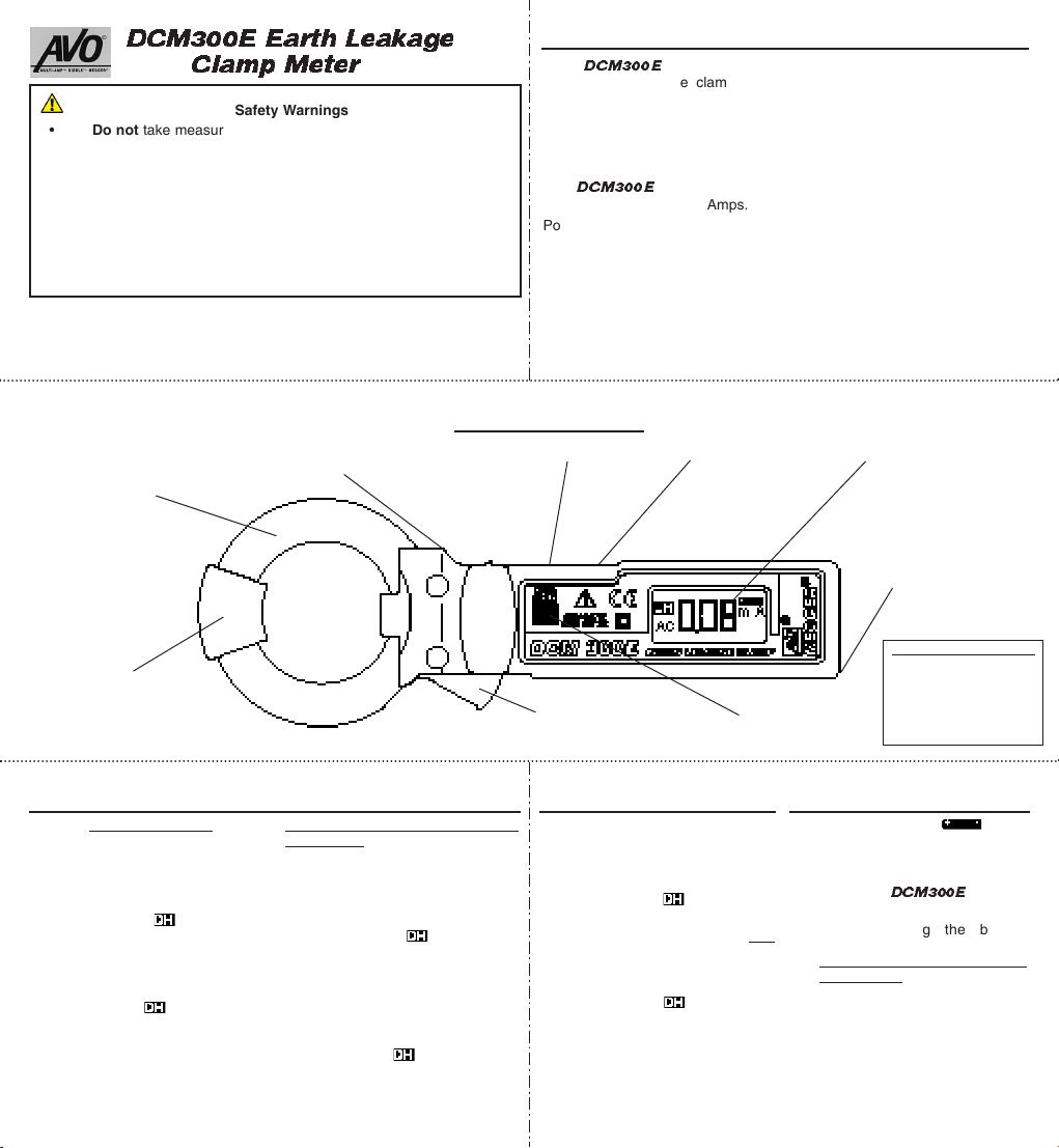
Transducer Jaws
S
must be read and understood before the
observed during use.
NO
TE
Tactile Handguard
Mode Selector Switch (mA / A)
Features and Controls
General Description
The
DCM300E
lightweight pocket size clamp meter
esigned to measure a.c. earth
d
leakage currents. This enables earth
eakage faults to be detected and
l
located without having to isolate and
disconnect circuit wiring. Additionally,
he
t
DCM300E
circuit currents up to 300 Amps.
Powered by two LR44 or SR44 cells,
the instrument design takes full
advantage of microprocessor
technology and features a clear 3
digit LCD combining digital and bargraph analogue readings.
is a rugged
easures a.c.
m
On / Off Switch
The two position mode switch
provides 4 ranges; 30 mA, 300 mA,
0 A and 300 A, with minimum
3
resolution of 0,01 mA on the 30 mA
ange.
r
To conserve battery power,
hut offoperates after a period of
s
10 minutes of inactivity by the
instrument. The instrument can be
switched back on by selecting
and then On again.
1
⁄2
31⁄2 Digit LCD Display
Wrist Strap point
Auto
Off
Jaw Guard
Measurement of Leakage Current
Earth Conductors
1) Set the range selector switch to
the 30 /300 mA position.
2) Set the Power switch to
3) Ensure that the Data hold
switch is Off. is not
displayed.
4) Clamp the jaws around the
earth conductor.
5) If necessary, press the Data
hold switch. is displayed.
6) Take the reading from the
Digital and/or Bar-graph display
On.
.
Single phase or 3 phase
conductors
1) Set the range selector switch to
the 30 /300 mA position.
2) Set the Power switch to On.
3) Ensure that the Data hold
switch is Off. is not
displayed.
4) Clamp the jaws around the two
single phase conductors, or the
3 conductors in the case of 3
phase.
If necessary
5)
hold switch. is displayed.
6) Take the reading from the
Digital and/or Bar-graph display.
, press the Data
Battery Cover Screw
The correct size screw
must be used and
Jaw Opening Lever
Data Hold Switch
fitted to ensure battery
cover security, and
safe operation.
Measurement of Line Current Battery Replacement
1) Set the range selector switch to
the 30 /300 mA position.
2) Set the Power switch to On.
3) Ensure that the Data hold
switch is Off. is not
displayed.
4) Clamp the jaws around
conductor of the circuit under
test.
5) If necessary, press the Data
hold switch. is displayed.
6) Take the reading from the
Digital and/or Bar-graph display.
1) When the symbol
appears on the display, the two
1,5 V button cells must be
replaced.
2) Switch the
3) Loosen the small cross head
one
screw securing the battery
cover, and remove the cover.
Take care not to lose the
small screw.
4) Remove both exhausted cells
and carefully fit two new cells
into the recess. Position both
cells +ve side up.
5) Replace the battery
compartment cover and resecure with the small cross
head screw.
DCM300E
Off.
Page 2

Specification
Display: 31⁄2 digit L.C.D.
aximum Indication:
M
Over Range Indication:
ata Hold Indication:
D
Low Battery Indication:
Auto Shut-Off: Operates after approximately 10 minutes
Accuracy: 50 / 60 Hz at 23 °C ± 5 °C and 80% R H
Range Min. Resolution Accuracy
30 / 300 mA 0,1 mA ± 1,2% of reading ± 5 digits.
30 / 300A 0,01 mA 0 - 200A ± 1,2% of reading ± 5 digits.
Limitation of Circuit Voltage: Less than 600 V a.c.
Sampling Time: Digital - Approx 2 x per second.
Operating Temperature: 0˚C -40˚C, <80% RH (Non
condensation).
Storage Temperature: -10˚C -60˚C, <70% RH (Non condensation).
Power Source: 2 x 1,5 V Button battery type LR44
Power Consumption: Approx 5 mW.
Battery Life: Typically 50 hours.
Flash Test: 3700 V a.c. / 1 minute max (Between CT
Safety: Meets the requirements for double insulation to IEC 1010-2-032,
IEC1010-1 (1995), EN 61010-1 (1995) installation Category II*,
600 Volts phase to earth, Category III** 300 V phase to earth,
500 Volts phase to phase.
E.M.C: The instrument meets EN 50081-1 and EN 50082-1 (1992).
Jaw Opening Capability: 40 mm diameter.
Dimensions: 64 mm x 176 mm x 23 mm
Weight: Approximately 125 gm.
Cleaning: Wipe with a clean cloth damped with soapy water or Isopropyl
Alcohol (IPA).
* Relates to transient overvoltage likely to be found in portable equipment
and appliances.
** Relates to transient overvoltage likely to be found in fixed installation
wiring.
200.
3
2.5 V ~ 2,7 V
f instrument inactivity.
o
non condensing.
200 - 250A - 3,0% of reading ± 5 digits.
250 - 300A ± 5,0% of reading ± 5 digits.
Analogue - Approx 12 x per second.
or SR44.
core and housing).
Repair and Warranty
he instrument circuit contains static sensitive devices, and care must be
T
taken in handling the printed circuit board. If the protection of an instrument
as been impaired it should not be used, and be sent for repair by suitably
h
trained and qualified personnel. The protection is likely to be impaired if, for
example, the instrument shows visible damage, fails to perform the intended
easurements, has been subjected to prolonged storage under
m
unfavourable conditions, or has been exposed to severe transport stresses.
New Instruments are Guaranteed for 1 Year from the Date of Purchase
Any unauthorized prior repair or adjustment will automatically
Note:
invalidate the Warranty.
Instrument Repair and Spare Parts
For service requirements for
AVO INTERNATIONAL or AVO INTERNATIONAL
Archcliffe Road 510 Township Line Road
Dover Bluebell
Kent, CT17 9EN PA 19422-2795
England U.S.A.
Tel: +44 (0) 1304 502243 Tel: +1 (215) 646-9200
Fax: +44 (0) 1304 207342 Fax: +1 (215) 643-7215
or an approved repair company.
Approved Repair Companies
A number of independent instrument repair companies have been approved
for repair work on most
spare parts. Consult the Appointed Distributor / Agent regarding spare parts,
repair facilities and advice on the best course of action to take.
Returning an Instrument for Repair
If returning an instrument to the manufacturer for repair, it should be sent
freight pre-paid to the appropriate address. A copy of the Invoice and of the
packing note should be sent simultaneously by airmail to expedite clearance
through Customs. A repair estimate showing freight return and other
charges will be submitted to the sender, if required, before work on the
instrument commences.
Symbols used on the instrument:
Caution: Refer to accompanying notes.
Equipment protected hroughout by Double Insulation (Class
Equipment complies with EU Directives
by the User.
MEGGER®Instruments contact :-
MEGGER® instruments, using genuine
MEGGER
II).
®
AVO
Archcliffe Road 510 Township Line Road 561 S.Westmoreland Road
Dover Bluebell Dallas
Kent, CT17 9EN.
England. U.S.A. U.S.A.
Tel: +44 (0) 1304 502100 Tel: +1 (215) 646-9200 Tel: +1 (8oo) 723-2861 (U.S.A. only)
Fax: +44 (0) 1304 207342 Fax: +1 (215) 643-2670 Tel: +1 (214) 330-3203 (International)
The company reserves the right to change the specification or design without prior notice
MEGGER
is the registered Trade Mark of AVO INTERNATIONAL LIMITED. This data uses the comma as the decimal marker to align with general European usage
Copyright © AVO INTERNATIONAL LIMITED. Part No. 6172-172 Edition 1 - 11BB
INTERNATIONAL
19422-2795 TX 75237-1017
A
P
Fax: +1 (214) 337-3038
 Loading...