

Page 1

DCM1500 clampmeter
User Guide
Manuel de l’utilisateur
Guía del usuario
Bedienungsanleitung
Gebruikershandleiding
Page 2
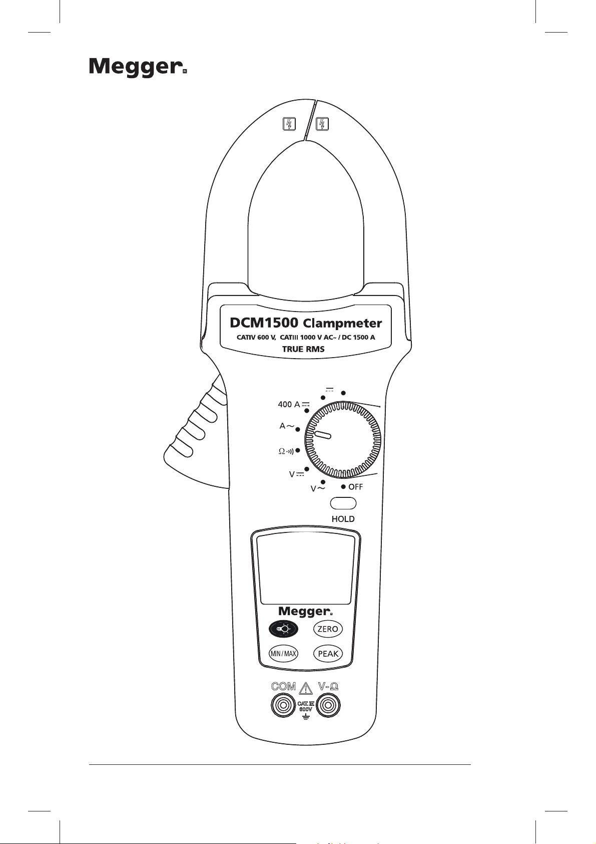
1500 A
Hz
2
Page 3

Safety Information
G
To ensure safe operation and service of the meter,
follow these instructions. Failure to observe warnings can
result in severe injury or death.
Q Avoid working alone so assistance can be rendered.
Q To enhance safety, test leads should be disconnected from
instrument when not in use
Q Do not use test leads or the clamp meter if they
look damaged
Q Do not use the clamp meter if the tester is not operating
properly or if it is wet.
Q Use the clamp meter only as specified in the instruction
card or the protection provided by the clamp meter may be
impaired.
Q Special precautions are necessary when operating in
situations where exposed live parts at dangerous voltages may
be encountered. Personal protective equipment (not supplied
with the instrument) should be used.
Q The test leads should be disconnected from the instrument
when making a current measurement.
Q Use caution with voltages above 30 V AC RMS, or 60 V DC.
These voltages pose a shock hazard.
Symbols as marked on the meter and
instruction card
F Risk of electric shock
G See instruction card
d DC measurement
t Equipment protected by double or reinforced insulation
Battery
Earth
g
a AC measurement
c Conforms to EU directives
GCaution: If the meter is used in the vicinity of equipment which
generates electromagnetic interference, the display may become unstable
or the measurements may be subject to large errors.
3
Page 4
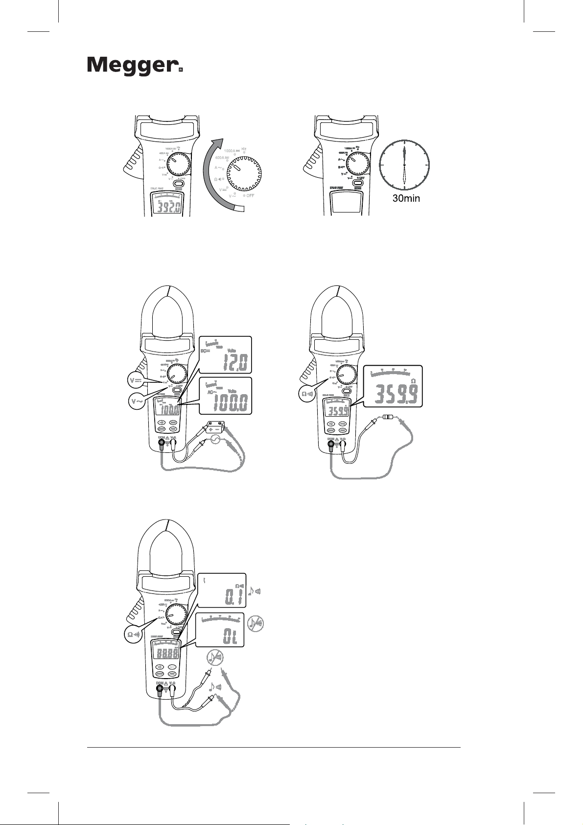
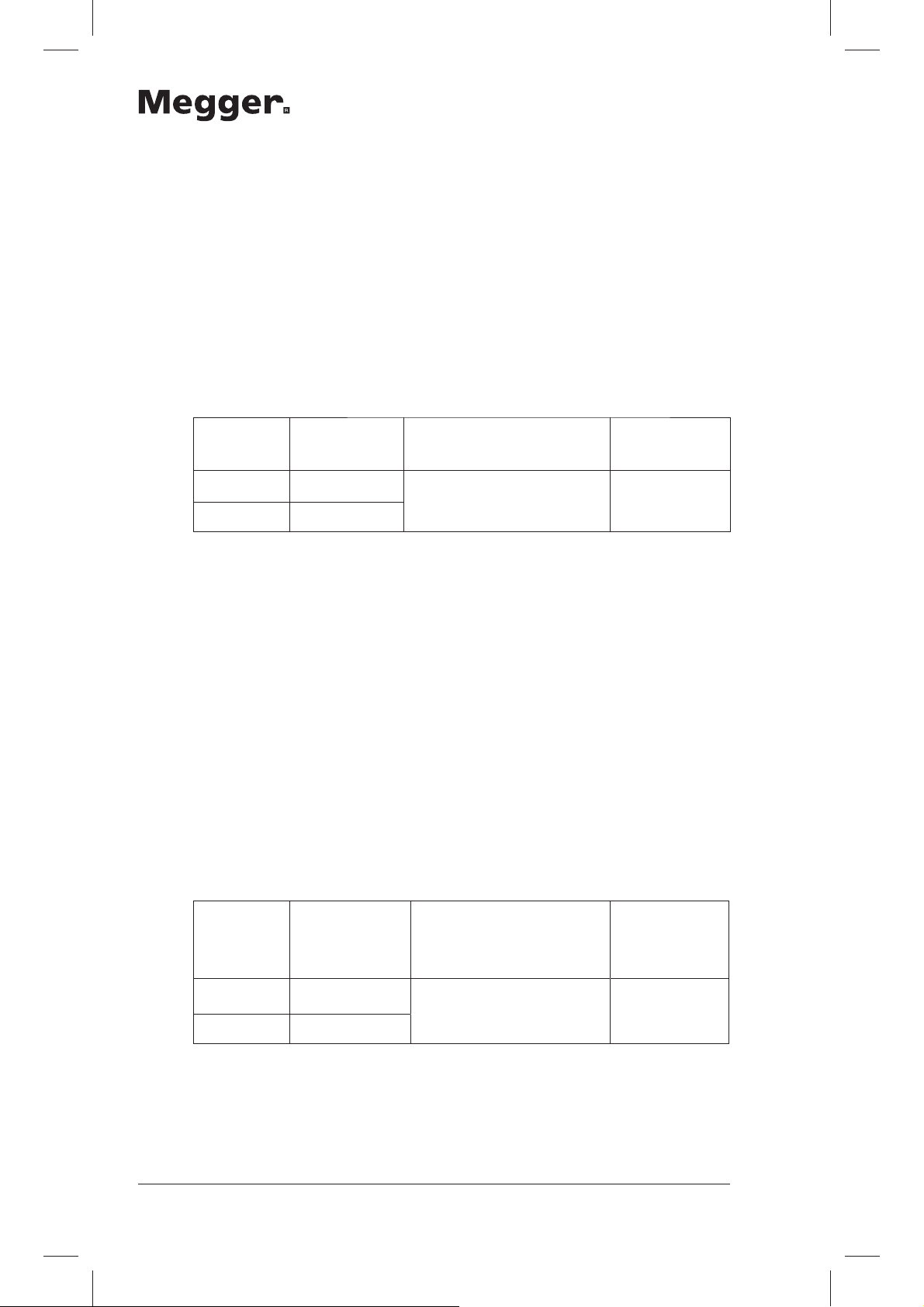
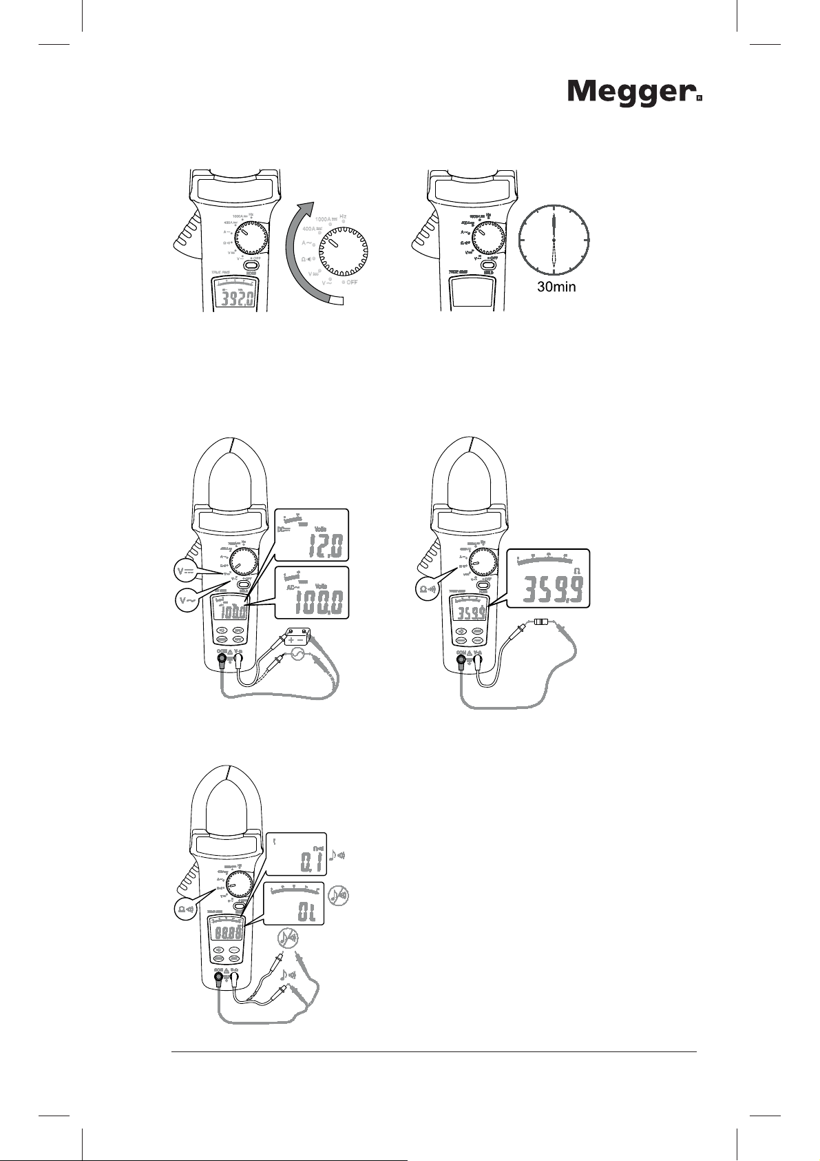
Off/On Auto Power Off
Auto Power Off disable: Press buttons (except Hold button) then
switch the rotary knob to power on the meter.
AC V / DC V Resistance
Continuity
4
Page 5

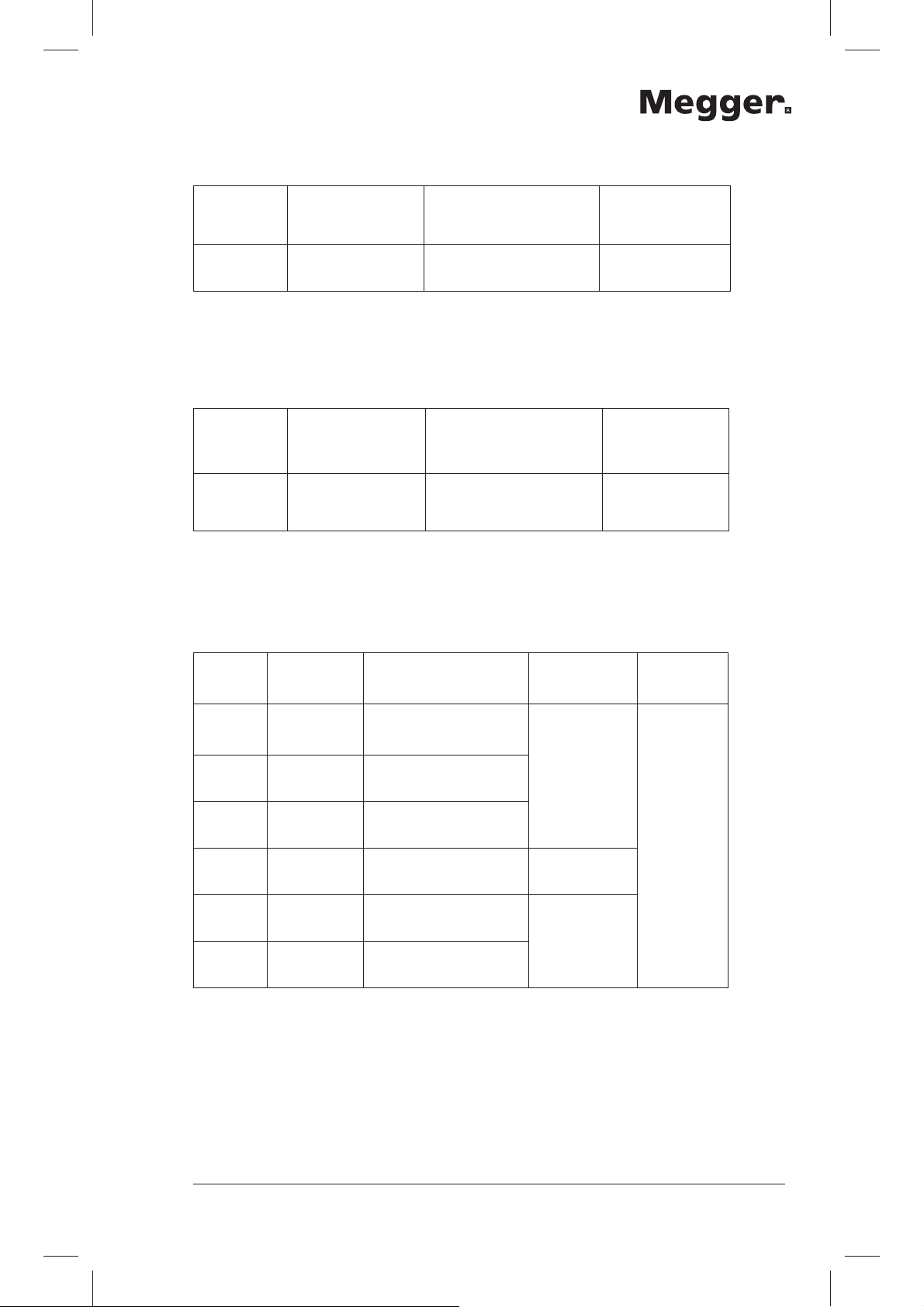
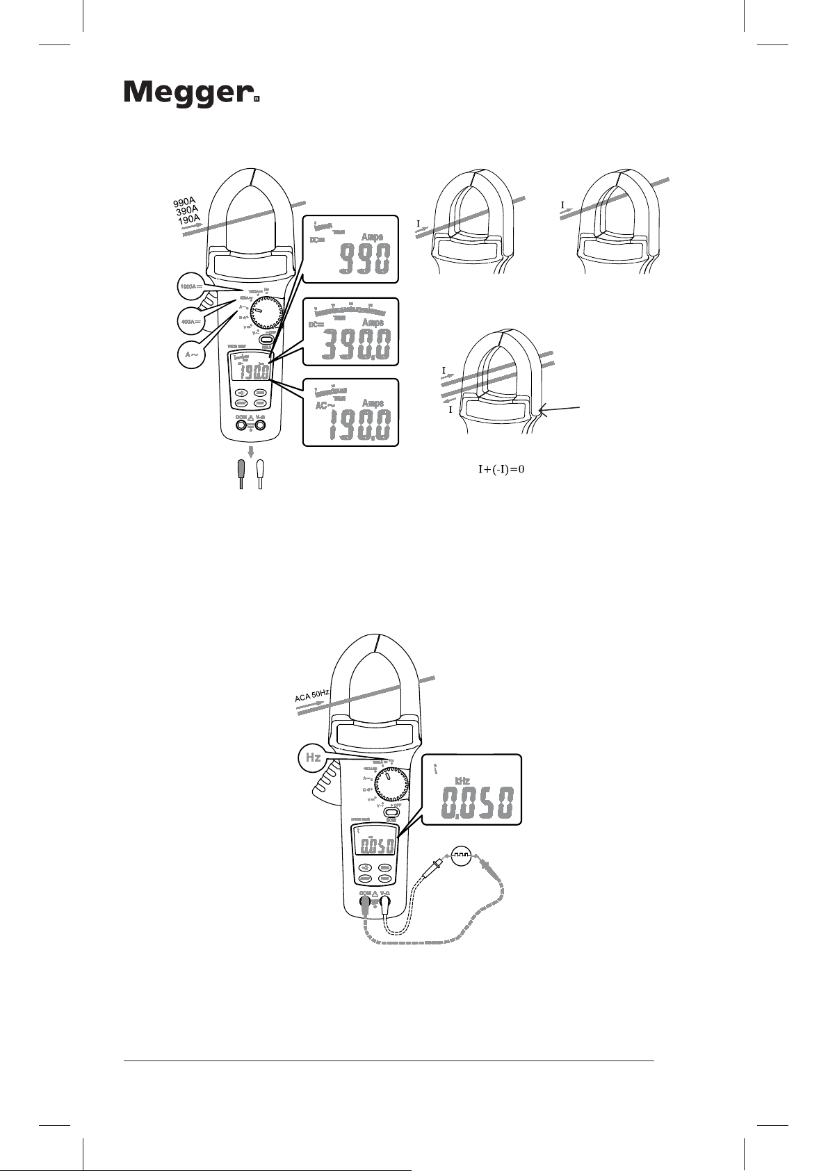
AC A / DC A
ϑ
Tactile barrier for
hand guard
G CAT IV 600 V - With respect to earth for the jaw
GDo not hold the meter in front of the tactile barrier.
Hz
5
Page 6

Zero
Using the Relative mode (REL), a stable value can be stored, the instrument
zeroed at that point, and then any variation from that value is displayed as
a direct measurement relative to the stable value.
2. Make a measurement and then press the ZERO button.
REL: Meter stores the measured value after pressing the
ZERO button.
3. REL (flashing): The meter saves the offset value. Present
value is displayed.
1. Normal: Press and hold ZERO for > 2 seconds to return
to normal operation and cancel the offset value.
Data Hold
6
Page 7
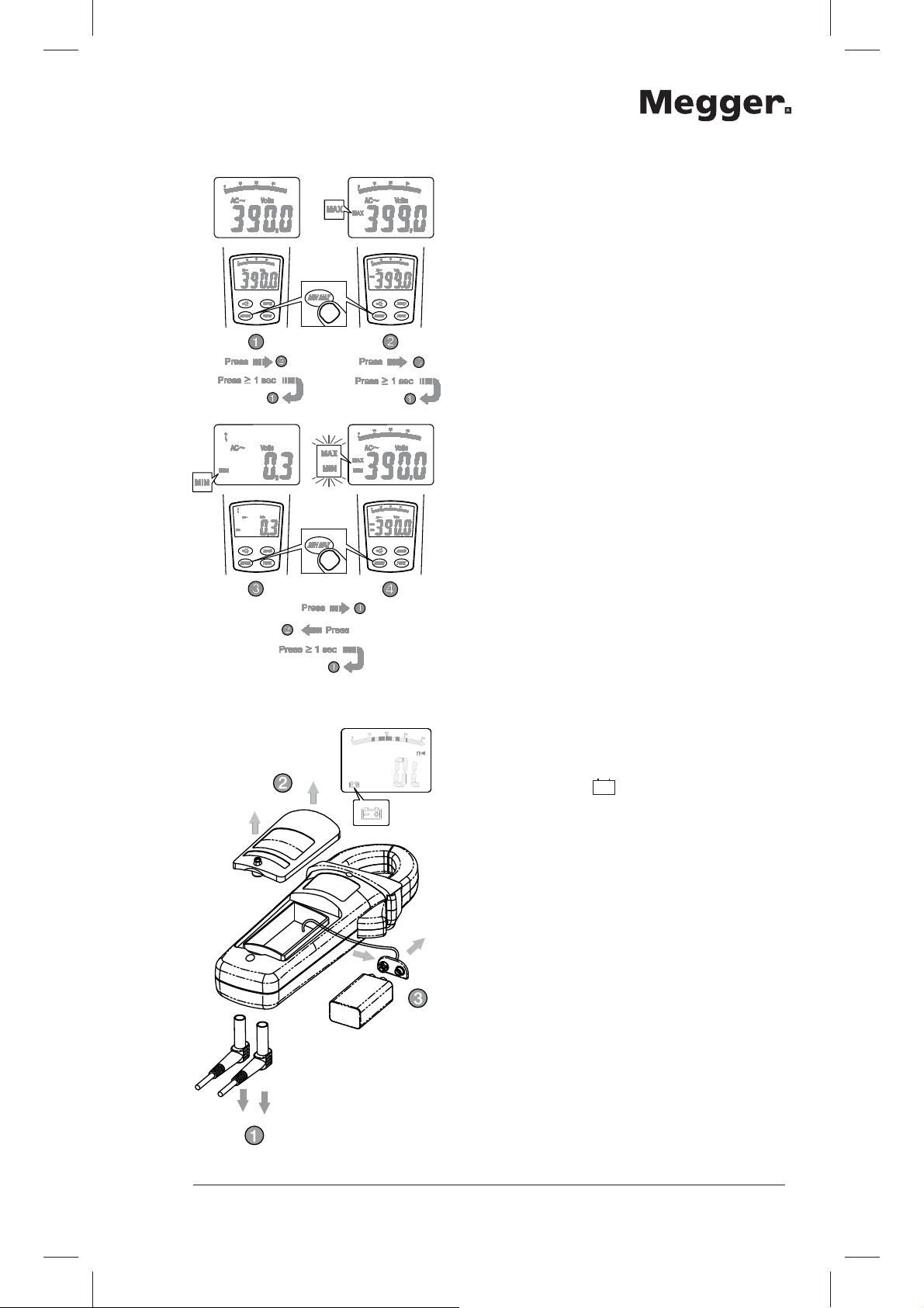
Min / Max Hold
2. MAX: Meter is saving
the maximum and
minimum value.
Maximum value is
displayed.
3. MIN: Meter is saving
the maximum and
minimum value.
Minimum value is
displayed.
4. MAX MIN (flashing):
Meter is saving the
maximum and
minimum value. Present
value is displayed.
1. Normal: Press and hold
MIN MAX to return to
normal operation.
Battery Replacement
Replace battery: is displayed.
7
Page 8
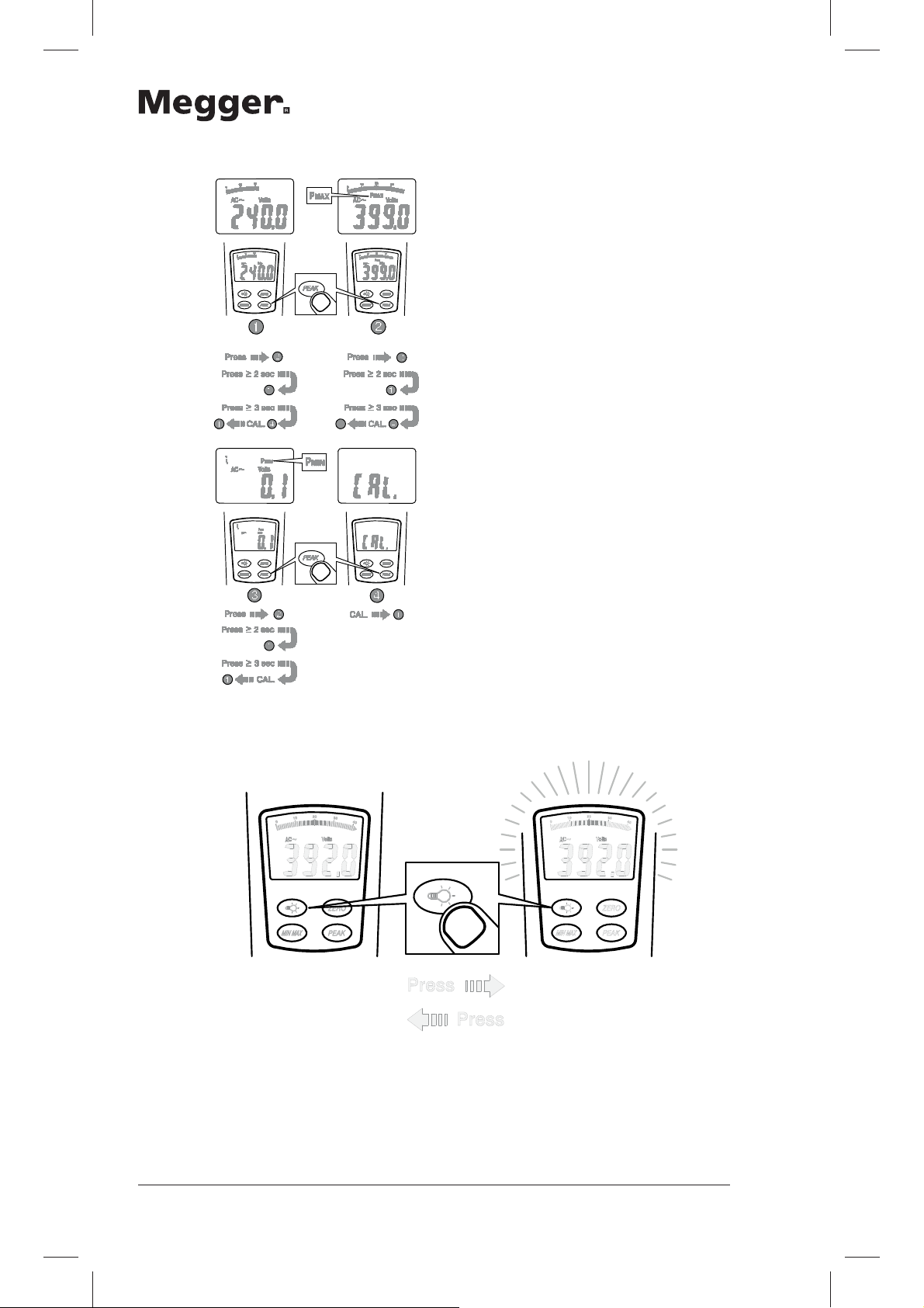
Peak Hold
2. PMax: Meter is saving
the peak maximum and
minimum value. Peak
maximum value id
displayed.
3. PMin: Meter is saving
the peak maximum and
minimum value. Peak
minimum value is
displayed.
4. CAL: Press and hold
PEAK button >
3seconds to calibrate
the instrument for
accurate measurement.
1. Normal: Press and
hold PEAK button to
return to normal
operation.
Back Light
Back light Automatic off after 60 seconds.
8
Page 9

Specifications
General Specifications
LCD display digits: 3 ¾ digit large scale LCD readout.
Display count: 4000 counts.
Measuring rate: 1.5 times / sec.
Overrange display: “OL” is displayed for “Ω” functions, shows
the real value for “A” and “V” function.
Automatic power off time:
Approximately 30 minutes after power on.
Low battery indicator:
when the indicator
the display.
Power requirement: 9 V PP3 / 6LR61 battery.
Rechargeable batteries are not recommended
for use with this instrument.
Battery life: 100 hours.
is displayed. Replace the battery
appears in
Environmental Conditions
Indoor Use.
Calibration: One year calibration period is recommended
Operating temperature :
0°C ~ 30°C (≤ 80 % RH)
30°C ~ 40°C (≤ 75 % RH)
40°C ~ 50°C (≤45 % RH)
Storage temperature:
-20 to +60°C, 0 to 80% RH
(batteries not fitted).
Measurement Category:
(acc. to CAT IV 600 V)
Application around and removal from UNINSULATED HAZARDOUS LIVE
conductors permitted. Personal protection must always be observed.
Operating altitude: 2000m (6562 ft)
Conductor Size: 51mm diameter.
Pollution degree: 2
EMC: EN 61326-1
Shock vibration: Sinusoidal vibration per MIL-T- 28800E
(5 ~ 55 Hz, 3g maximum).
9
Page 10
1-3 Electrical Specifications
Accuracy is ±(% reading + number of digits) at 23°C ± 5°C, less than 80%
R.H.
Temperature coefficient:
0.2 × (Specified accuracy) /°C, <18°C, >28°C
Operating temperature:
0°C ~ 30°C (≤ 80% RH)
30°C ~ 40°C (≤ 75% RH)
40°C ~ 50°C (≤ 45% RH)
AC Volts: Auto-ranging
Range Resolution Accuracy
400.0 V 100 mV
750 V 1 V
* add 2 digits to accuracy when reading less 15% of full scale.
±(1.0% reading + 5 digits)
50Hz ~ 500Hz *
Over voltage
protection
750 V rms
Input Impedance: ≥1MΩ// less than 100pF.
AC Conversion Type:
AC Conversions are ac-coupled, true rms responding, calibrated to the rms
value of a sine wave input. Accuracies are given for sine wave at full scale
and non-sine wave below half scale. For non-sine wave add the following
Crest Factor corrections:
For Crest Factor of 1.4 to 2.0, add 1.0% to accuracy.
For Crest Factor of 2.0 to 2.5, add 2.5% to accuracy.
For Crest Factor of 2.5 to 3.0, add 4.0% to accuracy.
Max.CF 2 @ 600V
1.5 @ 750V
DC Volts: Auto-ranging
10
Range Resolution Accuracy
400.0 V 100 mV
± (0.7% reading + 2 digits) 1000 V rms
1000 V 1 V
Input Impedance: ≥1MΩ
Over voltage
protection
Page 11
Resistance Auto-ranging
Range Resolution Accuracy
400.0Ω 100mΩ
±(1.0% reading + 3
digits)
Over voltage
protection
600V rms
Continuity: Built-in buzzer sound when resistance is less
than 30 Ω approximately.
Frequency (for ACA)
Range Resolution Accuracy
400Hz 1Hz
±(0.1% reading + 2
digits)
Min. Input Frequency: 20Hz
Sensitivity: 3A rms for < 400Hz
Over voltage
protection
AC/DC 1000A
for 1 min.
ACA
Range Resolution Accuracy
400A 0.1A
1000A 1A
1500A 1A
400A 0.1A
1000A 1A
1500A 1A
±(1.5% reading + 5
digits) *
±(1.9% reading + 7
digits)
±(2.5% reading + 7
digits)
±(1.9% reading + 5
digits) *
±(2.5% reading + 7
digits)
±(3.0% reading + 7
digits)
Frequency
Response
50Hz ~ 60Hz
61Hz ~ 400Hz
61Hz ~ 200Hz
Overload
protection
1500A rms
AC Conversion Type: * add 2 digits to accuracy when reading less
15% of full scale.
AC Conversions are ac-coupled, true rms responding, calibrated to the rms
value of a sine wave input. Accuracies are given for sine wave at full scale
and non-sine wave below half scale. For non-sine wave add the following
Crest Factor corrections:
For Crest Factor of 1.4 to 2.0, add 1.0% to accuracy.
11
Page 12

For Crest Factor of 2.0 to 2.5, add 2.5% to accuracy.
For Crest Factor of 2.5 to 3.0, add 4.0% to accuracy.
Max.CF 2 @ 600A
1.5 @ 1500A
DCA
Range Resolution Accuracy
400A 0.1A ±(1.0% reading + 3 digits)
1000A 1A ±(1.9% reading + 7 digits)
1500A 1A ±(2.5% reading + 7 digits)
Position Error: Add ±1% of LCD reading.
Over voltage
protection
AC 1000A
for 1 min.
Auto Power Off (APO)
The meter will automatically shut itself off after approximately 30 minutes
after power on.
Peak Hold: ±(3% reading +10 digits)
* >750V Unspecified.
* >800A Unspecified.
Min/Max Hold: Add ± 15 digits to accuracy for ACA and DCA.
Maintenance
12
Do not attempt to repair this meter. It contains no user-serviceable parts.
Repair or servicing should only be performed by qualified personnel.
Cleaning
Periodically wipe the case with a dry cloth and detergent, do not use
abrasives or solvents.
CATIV Measurement category IV: Equipment connected between
the origin of the low-voltage mains supply outside the
building and the consumer unit.
CATIII Measurement category III: Equipment connected between
the consumer unit and the electrical outlets.
CATII Measurement category II: Equipment connected between
the electrical outlets and the user’s equipment.
Page 13

WEEE Directive
The crossed out wheeled bin symbol on the instrument and on the batteries
is a reminder not to dispose of them with general waste at the end of their
life.
Megger is registered in the UK as a Producer of Electrical and Electronic
equipment. The registration no is; WEE/DJ2235XR.
Users of Megger products in the UK may dispose of them at the end of
their useful life by contacting B2B Compliance at www.b2bcompliance.org.
uk or by telephone on 01691 676124.
Users of Megger products in other parts of the EU should contact their local
Megger company or distributor.
Battery Disposal
Batteries in this product are classified as Portable Batteries under the
Batteries Directive. Please contact Megger Ltd for instructions on the safe
disposal of these batteries.
Q For disposal of batteries in other parts of the EU
contact your local distributor.
Q Megger is registered in the UK as a producer of batteries.
Q The registration number is BPRN01235.
Q For Further information see www.megger.com
Limited Warranty
This meter is warranted to the original purchaser against defects in
material and workmanship for 1 year from the date of purchase. During
this warranty period, manufacturer will, at its option, replace or repair the
defective unit, subject to verification of the defect or malfunction.
This warranty does not cover fuses, disposable batteries, or damage from
abuse, neglect, accident, unauthorised repair, alteration, contamination, or
abnormal conditions of operation or handling.
Any implied warranties arising out of the sale of this product, including
but not limited to implied warranties of merchantability and fitness for a
particular purpose, are limited to the above. The manufacturer shall not be
liable for loss of use of the instrument or other incidental or consequential
damages, expenses, or economic loss, or for any claim or claims for such
damage, expense or economic loss. Some states or countries laws vary, so
the above limitations or exclusions may not apply to you.
13
Page 14

Pince ampèremétrique DCM1500
Manuel de l’utilisateur
Page 15
1500 A
Hz
15
Page 16

Informations de sécurité
G
Appliquez les instructions suivantes afin de garantir le fonctionnement
et l’entretien de la pince en toute sécurité.
Le non-respect des consignes peut causer de graves blessures ou la
mort.
Q Évitez de travailler seul pour pouvoir vous faire aider.
Q Pour plus de sécurité, débranchez les cordons de test de l’instrument
lorsque vous ne l’utilisez pas.
Q N’utilisez pas les cordons de test ni la pince ampèremétrique s’ils vous
semblent endommagés.
Q N’utilisez pas la pince ampèremétrique si elle ne fonctionne pas
correctement ou si elle est mouillée.
Q Utilisez toujours la pince ampèremétrique conformément aux
instructions. À défaut, vous risqueriez d’altérer la protection intégrée à
cette dernière.
Q Des précautions particulières doivent être prises lorsque vous travaillez
dans environnement comportant des pièces alimentées par une tension
dangereuse. Utilisez un équipement de protection individuelle (non
fourni avec l’instrument).
Q Débranchez les cordons de test de l’instrument lorsque vous mesurez
le courant.
Q Faites preuve de prudence lorsque la tension dépasse 30 V C.A. RMS
ou 60 V C.C. Ces tensions présentent un risque d’électrocution.
Symboles figurant sur la pince et sur la fiche
d’instructions
F Risque d’électrocution
G Consultez la fiche d’instructions
d Mesure en C.C.
t Équipement protégé par une isolation double ou renforcée
Pile
g Terre
a Mesure en C.A.
c Conforme aux directives européennes
GAttention: La proximité d’un équipement qui génère des interférences
électromagnétiques lors du fonctionnement de la pince peut causer un
affichage instable ou des erreurs importantes dans les mesures.
16
Page 17
Marche/Arrêt Arrêt automatique
Désactivation de l’arrêt automatique: Appuyez sur des boutons
(sauf le bouton Hold (Maintien)), puis tournez le bouton rotatif pour activer
la pince
V CA / V CC Résistance
Continuité
17
Page 18
A C.A. / A C.C.
ϑ
Barrière tactile pour
protège-main
G CAT IV 600 V - Par rapport à la terre pour la mâchoire
G Ne tenez pas la pince devant la barrière tactile.
Hz
18
Page 19

Zero
Il est possible d’enregistrer une valeur stable à l’aide du mode relatif (REL),
l’instrument se met à zéro à ce point, puis toute variation de cette valeur
s’affiche comme mesure directe par rapport à la valeur stable.
2. Effectuez une mesure puis appuyez sur le bouton ZERO
(Zéro).
REL (mode relatif) : Une fois que vous avez appuyé sur le
bouton ZERO (Zéro), la pince enregistre la valeur mesurée.
3. REL (clignotant) : La pince enregistre la valeur de décalage.
La valeur présente s’affiche.
1. Normal : Appuyez sur le bouton ZERO (Zéro) et
maintenez-le enfoncé plus de deux secondes pour revenir
au fonctionnement normal et annuler la valeur de décalage.
Maintien des données
19
Page 20

Maintien min./max.
2. MAX (Max.) : La pince
enregistre la valeur
maximale et minimale. La
valeur maximale s’affiche.
3. MIN (Min.) : La pince
enregistre la valeur
maximale et minimale. La
valeur minimale s’affiche.
4. MAX MIN (Max. Min.)
(clignotant) : La pince
enregistre la valeur
maximale et minimale. La
valeur présente s’affiche.
1. Normal : Appuyez sur le
bouton MIN MAX (Min.
Max.) et maintenez le enfoncé pour revenir
au fonctionnement
normal.
Remplacement de la batterie
Remplacez la batterie :
s’affiche.
20
Page 21

Maintien de crête
2. PMax : La pince
enregistre la valeur
maximale et la valeur
minimale de crête.
La valeur maximale de
crête d’affiche.
3. PMin : La pince enregistre
la valeur maximale et
minimale de crête. La
valeur minimale de crête
s’affiche.
4. CAL : Appuyez sur
le bouton PEAK (Crête)
et maintenez-le enfoncé
plus de 3 secondes pour
étalonner l’instrument et
obtenir des mesures
précises.
1. Normal : Appuyez
sur le bouton PEAK
(Crête) et maintenez le enfoncé pour revenir
au fonctionnement
normal.
Rétroéclairage
Le rétroéclairage automatique s’éteint après 60 secondes.
21
Page 22

Spécifications
Spécifications générales
Points de l’écran LCD: Lecture LCD grande échelle à
3 ¾ chiffres.
Compte de l’écran : 4000 comptes.
Fréquence de mesure : 1,5 fois/s.
Affichage de dépassement :
« OL » (hors limite) s’affiche pour les
fonctions « Ω », affiche la valeur réelle pour
les fonctions « A » et « V ».
Délai de l’arrêt automatique :
Environ 30 minutes après l’activation.
Indicateur de batterie faible :
batterie lorsque l’indicateur
Alimentation requise : Batterie 9 V PP3 / 6LR61.
Il est déconseillé d’utiliser des piles
rechargeables avec cet instrument.
Autonomie de la batterie:
100 heures.
s’affiche. Remplacez la
s’affiche à l’écran.
Conditions environnementales
Utilisation intérieure.
Étalonnage: La fréquence d’étalonnage recommandée
est d’un an
Température de fonctionnement :
0 ~ 30 °C (≤80 % HR)
30 ~ 40°C ≤75% HR)
40 ~ 50 °C (≤45 % HR)
Température de stockage :
De -20 à +60 °C, de 0 à 80 % HR
(sans les batteries).
Catégorie des mesures :
(conformément à CAT IV 600 V)
Retrait et application autour de conducteurs DANGEREUX SOUS TENSION
NON ISOLÉS autorisés. Utilisez toujours un équipement de protection
individuelle.
Altitude de fonctionnement :
2 000 m (6 562 ft)
Taille du conducteur : 51 mm de diamètre.
Degré de pollution: 2
CEM: EN 61326-1
Vibration par choc: Vibration sinusoïdale selon MIL-T- 28800E
(5 ~ 55 Hz, 3 g maximum).
22
Page 23

Spécifications électriques
La précision est de ±(relevé en % + chiffres) à 23 °C ±5 °C, moins de 80 %
HR.
Coefficient de température:
0,2 × (précision spécifiée) /°C,
<18 °C, >28 °C
Température de fonctionnement :
0 ~ 30 °C (≤80 % HR)
30 ~ 40°C (≤75% HR)
40 ~ 50°C (≤45% HR)
V AC : Détermination automatique des mesures
effectuées
Plage Résolution Précision
400,0 V 100 mV
750 V 1 V
* ajoutez deux chiffres à la précision lorsque le relevé est inférieur à 15 % de la pleine
échelle.
Impédance d’entrée: ≥1 MΩ// moins de 100 pF.
±(relevé de 1 % + 5 chiffres)
50 ~ 500 Hz *
Surtension
protection
750 V rms
Type de conversion C.A:
Les conversions C.A. sont couplées en C.A., véritablement réactives rms,
étalonnées à la valeur rms d’une entrée en régime sinusoïdal. Les précisions
sont données pour un régime sinusoïdal à pleine échelle et pour un régime
non sinusoïdal lorsque l’échelle est inférieure à la moitié. Pour un régime
non sinusoïdal, ajoutez les corrections de facteur de crête suivantes :
Pour un facteur de crête de 1,4 à 2,0, ajoutez 1 % à la précision.
Pour un facteur de crête de 2,0 à 2,5, ajoutez 2,5 % à la précision.
Pour un facteur de crête de 2,5 à 3,0, ajoutez 4 % à la précision.
Facteur de crête max: 2 à 600 V
1,5 à 750 V
V C.C. : Détermination automatique des
mesures effectuées
Plage Résolution Précision
400,0 V 100 mV
1000 V 1 V
Impédance d’entrée : ≥1 MΩ
±(relevé de 0,7 % + 2
chiffres)
Surtension
protection
1000 V rms
23
Page 24

Détermination automatique des mesures
effectuées pour la résistance
Protection
Plage Résolution Précision
contre les
surtensions
400,0 Ω 100 mΩ
±(relevé de 1 % + 3
chiffres)
600V rms
Continuité : Signal sonore intégré quand la résistance
descend en dessous de 30 Ω environ.
Fréquence (pour A C.A.)
Plage Résolution Précision
400,0 Hz 1 Hz
±(relevé de 0,1 % + 2
chiffres)
Fréquence d’entrée minimale : 20Hz
Sensibilité : 3 A rms pour < 400 Hz
Surtension
protection
1 000 A
CA/CC pour
1 min.
A C.A.
Plage Résolution Précision
Fréquence
Réponse
Surtension
protection
400 A 0,1 A
1000 A 1 A
1500 A 1 A
400 A 0,1 A
1000 A 1 A
1500 A 1 A
±(relevé de 1,5 % +
5 chiffres) *
±(relevé de 1,9 % +
7 chiffres)
±(relevé de 2,5 % +
7 chiffres)
±(relevé de 1,9 % +
5 chiffres) *
±(relevé de 2,5 % +
7 chiffres)
±(relevé de 3 % + 7
chiffres)
50 Hz ~ 60 Hz
1500 A rms
61 Hz ~
400 Hz
61 Hz ~
200 Hz
Type de conversion CA: * ajoutez deux chiffres à la précision lorsque le relevé est
inférieur à 15 % de l’intégralité de l’échelle.
Les conversions CA sont couplées en CA, véritablement réactives rms,
étalonnées à la valeur rms d’une entrée en régime sinusoïdal. Les précisions
sont données pour un régime sinusoïdal à pleine échelle et pour un régime
non sinusoïdal lorsque l’échelle est inférieure à la moitié. Pour un régime
24
Page 25

non sinusoïdal, ajoutez les corrections de facteur de crête suivantes:
Pour un facteur de crête de 1,4 à 2,0, ajoutez 1 % à la précision.
Pour un facteur de crête de 2,0 à 2,5, ajoutez 2,5 % à la précision.
Pour un facteur de crête de 2,5 à 3,0, ajoutez 4 % à la précision.
Facteur de crête max 2 à 600 A
1,5 à 1500 A
A C.C
Protection
Plage Résolution Précision
400 A 0,1 A ±(relevé de 1 % + 3 chiffres)
contre la
surtension
1000 A 1 A ±(relevé de 1,9 % + 7 chiffres)
1500 A 1 A ±(relevé de 2,5 % + 7 chiffres)
Erreur de position: Ajoutez ±1 % au relevé LCD.
1 000 A pour
1 min.
Désactivation de l’arrêt automatique (APO)
La pince s’éteint automatiquement après environ 30 minutes d’activation.
Maintien de crête : ±(relevé de 3 % + 10 chiffres)
* >750 V non spécifié.
* >800 A non spécifié.
Maintien min./max:
Ajoutez ±15 chiffres à la précision pour A C.A. et A C.C.
25
Page 26

Maintenance
N’essayez pas de réparer cette pince. Elle ne contient aucune pièce qui
puisse être entretenue. Seul le personnel qualifié est autorisé à la réparer ou
à l’entretenir.
Nettoyage
Essuyez régulièrement le boîtier à l’aide d’un chiffon sec et de détergent,
n’utilisez pas d’abrasifs ni de solvants.
CATIV Catégorie IV des mesures : Équipement connecté entre
l’origine de l’alimentation secteur basse tension à
l’extérieur du bâtiment et l’unité consommateur.
CATIII Catégorie III des mesures : Équipement connecté entre
l’unité consommateur et les prises de courant.
CATII Catégorie II des mesures : Équipement connecté entre les
prises de courant et l’équipement de l’utilisateur.
Directive DEEE
Le symbole représentant une poubelle à roulettes barrée qui figure sur
l’instrument et sur les batteries est destiné à rappeler que ces équipements
ne doivent pas être éliminés avec les ordures ménagères au terme de leur
vie.
Megger est enregistré au Royaume-Uni comme fabricant d’équipements
électriques et électroniques. Le numéro d’enregistrement est WEE/
DJ2235XR.
Les utilisateurs d’appareil Megger au Royaume-Uni peuvent, à la fin de
la durée de vie des appareils, contacter B2B Compliance sur le site www.
b2bcompliance.org.uk ou par téléphone au 01691 676124 pour les mettre
au rebut.
Les utilisateurs d’appareils Megger ailleurs en UE doivent contacter leur
filiale Megger locale ou leur distributeur.
.
26
Page 27

Élimination des batteries
Selon la directive sur les batteries, les batteries de cet appareil sont
classées en tant que batteries portables. Contactez Megger Ltd pour savoir
comment éliminer sans danger ces batteries.
Q Pour la mise au rebut des batteries dans d’autres pays de l’UE,
contactez notre distributeur local.
Q Megger est enregistré au Royaume-Uni comme fabricant de
batteries.
Q Le numéro d’enregistrement est BPRN01235.
Q Pour de plus amples informations, consultez www.megger.com
Garantie limitée
Pour l’acheteur d’origine, cette pince est garantie contre les défauts de
matériel et de fabrication un an à partir de la date d’achat. Pendant cette
période de garantie, le fabricant remplacera ou réparera l’unité défectueuse
à son gré, en fonction de la vérification du défaut ou de la défaillance.
Cette garantie ne couvre pas les fusibles, les batteries jetables ou les
dommages causés par des abus, de la négligence, un accident, une
réparation non autorisée, la modification de l’appareil, sa contamination ou
des conditions anormales de fonctionnement ou de manutention.
Toutes garanties implicites résultant de la vente de cet appareil, comprenant
sans s’y limiter les garanties implicites de qualité marchande ou
d’adéquation à un usage particulier, se limitent à ce qui est susmentionné.
Le fabricant ne peut être tenu responsable pour la perte de l’utilisation de
l’appareil ou d’autres dommages, frais ou pertes économiques consécutifs
ou indirects, ou pour toute demande d’indemnités pour de tels dommages,
frais ou pertes économiques. La loi est différente dans certains états et
certains pays, il se peut par conséquent que les limitations susmentionnées
ne s’appliquent pas pour vous.
27
Page 28

Pinza amperimétrica DCM1500
Guía del usuario
Page 29

1500 A
Hz
29
Page 30

Información sobre seguridad
G
Para asegurarse de que la pinza amperimétrica se utiliza de forma segura,
siga las instrucciones siguientes.
De no seguirse las advertencias que se indican, el usuario podría sufrir
lesiones graves e incluso la muerte.
Q Evite trabajar solo, ya que podría necesitar ayuda.
Q A fin de mejorar las condiciones de seguridad, deben desconectarse los
cables de prueba del instrumento cuando no se esté utilizando.
Q No utilice los cables de prueba ni la pinza amperimétrica si presentan
daños.
Q No utilice la pinza amperimétrica si no funciona correctamente o si está
húmeda.
Q Utilice la pinza amperimétrica únicamente como se indica en la tarjeta
de instrucciones o, de lo contrario, la protección que proporciona
podría verse afectada.
Q Se deben tomar precauciones especiales al trabajar en situaciones
en las que se puedan encontrar elementos conductores expuestos por
los que circule corriente a tensiones peligrosas. Se deben utilizar
equipos de protección personales (no se suministran con el
instrumento).
Q Los cables de prueba se deben desconectar del instrumento al realizar
una medición de corriente.
Q Tenga cuidado con las tensiones con valores superiores a 30 V de CA
RMS o 60 V de CC. A estas tensiones existe riesgo de electrocución.
Símbolos que aparecen en la pinza
amperimétrica y en la tarjeta de instrucciones
F Riesgo de electrocución
G Consulte la tarjeta de instrucciones
d Medición de CC
t Equipo protegido por aislamiento doble o reforzado
Batería
g Conexión a tierra
a Medición de CA
c Cumple con las directivas de la UE
G Precaución: Si se utiliza la pinza amperimétrica en las proximidades
de equipos que generen interferencias electromagnéticas, la pantalla
podría volverse inestable o podrían producirse errores considerables en las
mediciones.
30
Page 31

Apagado/encendido Apagado automático
Desactivación del apagado
automático: Pulse los botones
(excepto el botón Hold [Retención])
y, a continuación, gire el botón
giratorio para encender la pinza
amperimétrica.
V de CA/V de CC Resistencia
31
Page 32

Continuidad
AC A / DC A
ϑ
Barrera táctil de
protección para
las manos
G CAT IV 600 V - Con respecto a la conexión a tierra de la pinza
32
GNo sostenga la pinza por la parte posterior de la barrera táctil.
Page 33

Hz
Ajuste del valor cero
Impresión Impresión
El modo relativo (botón REL [Valor relativo]) le permite almacenar un valor
estable y ajustar el instrumento a cero en dicho valor. A partir de entonces,
toda variación de dicho valor aparecerá como una medición directa con
respecto del valor estable configurado como cero.
2. Realice una medición y, a continuación, pulse el botón
ZERO (Ajuste valor cero).
REL (Valor relativo): La pinza amperimétrica almacena el
valor medido tras pulsar el botón ZERO (Ajuste valor cero).
3. REL (Valor relativo) (parpadeo): La pinza amperimétrica guarda el
valor configurado como cero. Se muestra el valor actual.
Impresión
33
Page 34

1. Ajustar al modo de funcionamiento normal: Mantenga
pulsado el botón ZERO (Ajuste valor cero) durante más de
2 segundos para volver al modo de funcionamiento normal
y cancelar el valor configurado como cero.
Retención de datos
Impresión
Retención de valores mín./máx
Impresión Impresión
Impresión Impresión
Impresión
Impresión
Impresión
2. MAX (Máx.): La pinza
amperimétrica está
almacenando los
valores máximo y mínimo.
Se muestra el valor
máximo.
3. MIN (Mín.): La pinza
amperimétrica está
almacenando los valores
máximo y mínimo. Se muestra
el valor mínimo.
4. MAX MIN (Máx./Mín.)
(parpadeo): La pinza
amperimétrica está
almacenando los valores
máximo y mínimo. Se muestra
el valor actual.
1. Ajustar al modo de
funcionamiento normal:
Mantenga pulsado el botón
MIN MAX (Mín./Máx.) para
volver al modo de
funcionamiento normal.
34
Page 35

Sustitución de la pila
Sustitución de la pila: aparece el símbolo .
Peak Hold
Impresión Impresión
Impresión Impresión
Impresión Impresión
Impresión
Impresión
Impresión
2. PMax (Rendim. máx.):
La pinza amperimétrica
está almacenando los
valores de rendimiento
máximo y mínimo. Se
muestra el valor de
rendimiento máximo.
3. PMin (Rendim. mín.):
La pinza amperimétrica
está almacenando los
valores de rendimiento
máximo y mínimo. Se
muestra el valor de
rendimiento mínimo.
4. CAL (Calibración):
Mantenga pulsado
el botón PEAK
(Rendimiento) durante
más de 3 segundos para
calibrar el instrumento
y poder realizar las
mediciones precisas.
1. Ajustar al modo de funcionamiento normal: Pulse y mantenga
pulsado botón PEAK (Rendimiento) para volver al modo de
funcionamiento normal.
35
Page 36

Retroiluminación
Impresión
Impresión
La retroiluminación se apagará automáticamente después de 60 segundos.
Specifications
Especificaciones generales
Dígitos de la pantalla LCD:
Pantalla LCD grande con lectura de 3
¾ de dígito.
Número de cuentas: 4000 cuentas.
Velocidad de medición: 1,5 veces/seg.
Mensaje en pantalla por rango excedido:
Aparecerá el mensaje “OL” (Sobrecarga)
para las funciones “Ω”. Se mostrarán los
valores reales de las funciones “A” y “V”.
Tiempo para el apagado automático:
Aproximadamente 30 minutos
después del encendido.
Indicador de batería baja:
Aparece el símbolo ‘
batería cuando aparezca en pantalla el
indicador ‘
Requisitos de alimentación: Pila PP3/6LR61 de 9 V.
No se recomienda utilizar pilas
recargables en este instrumento.
Duración de las pilas: 100 horas.
’.
’. Sustituya la
36
Condiciones ambientales
Uso en interiores.
Calibración: Se recomienda un período de calibración
de un año
Page 37

Temperatura de funcionamiento:
0 °C ~ 30 °C (humedad relativa ≤ 80%)
30 °C ~ 40 °C (humedad relativa ≤ 75%)
40°C ~ 50°C (humedad relativa ≤ 45%)
Temperatura de almacenamiento:
De -20 a +60 °C, con una humedad
relativa de entre el 0 y el 80%
(sin las pilas instaladas).
Categoría de medición:
(Precis. de hasta CAT IV 600 V)
El instrumento se puede utilizar y retirar de conductores PELIGROSOS NO
AISLADOS Y POR LOS QUE CIRCULA CORRIENTE. Siempre deben seguirse
las precauciones de seguridad.
Altitud de funcionamiento: 2000 m (6562 ft)
Tamaño del conductor: 51 mm de diámetro.
Grado de contaminación: 2
EMC: EN 61326-1
Choque y vibración: Vibración sinusoidal según la norma
MIL-T- 28800E (5 ~ 55 Hz, 3 g como máximo)
Especificaciones eléctricas
Precisión de ± (% de lectura + número de dígitos) a 23 °C ± 5 °C y a una
humedad relativa inferior al 80%.
Coeficiente de temperatura:
0,2 × (precisión especificada)/°C,
< 18 °C, > 28 °C
Temperatura de funcionamiento:
0 °C ~ 30 °C (humedad relativa ≤ 80%)
30°C ~ 40°C (humedad relativa ≤ 75%)
40°C ~ 50°C (humedad relativa ≤ 45%)
Voltaje de CA: Rango automático
Rango Resolución Precisión
400,0 V 100 mV
750 V 1 V
* Se deben añadir 2 dígitos a la precisión cuando la lectura es inferior a un 15% de la
escala completa.
± (1,0% de la lectura + 5
dígitos) 50 Hz ~ 500 Hz*
Protección ante
sobretensión
750 V RMS
Impedancia de entrada: ≥1 MΩ//menos de 100 pF.
37
Page 38

Tipo de conversión de CA:
Las conversiones de CA se acoplan en CA, son sensibles al RMS verdadero
y están calibradas al valor RMS de una entrada de onda sinusoidal. Las
precisiones corresponden a una onda sinusoidal de escala completa y a una
onda no sinusoidal de media escala. Para ondas no sinusoidales, añada las
siguientes correcciones del factor de cresta:
Para un factor de cresta de 1,4 a 2, añada un 1,0% a la precisión.
Para un factor de cresta de 2 a 2,5, añada un 2,5% a la precisión.
Para un factor de cresta de 2,5 a 3, añada un 4,0% a la precisión.
Factor de cresta (CF) máx 2 a 600 V
1,5 a 750 V
Voltaje de CC: Rango automático
Rango Resolución Precisión
400,0 V 100 mV
1000 V 1 V
Impedancia de entrada: ≥ 1 MΩ
± (0,7% de la lectura +
2 dígitos)
Protección ante
sobretensión
1000 V RMS
Rango automático de la resistencia
Rango Resolución Precisión
400 Ω 100 mΩ
± (1,0% de la lectura +
3 dígitos)
Continuidad: Sonará un zumbador integrado cuando la
resistencia sea inferior a aproximadamente 30 Ω.
Frecuencia (del A de CA)
Rango Resolución Precisión
Protección ante
sobretensión
600 V RMS
Protección ante
sobretensión
38
400 Hz 1 Hz
± (0,1% de la lectura
+ 2 dígitos)
CA/CC de 1000 A
durante 1 minuto.
Frecuencia de entrada mín: 20Hz
Sensibilidad: 3 A de valor eficaz para < 400 Hz
Page 39

A de CA
Protección
ante
sobrecarga
1500 A RMS
Rango Resolución Precisión
400 A 0,1 A
1000 A 1 A
1500 A 1 A
400 A 0,1 A
1000 A 1 A
1500 A 1 A
± (1,5% de la lectura
+ 5 dígitos) *
± (1,9% de la lectura
+ 7 dígitos)
± (2,5% de la lectura
+ 7 dígitos)
± (1,9% de la lectura
+ 5 dígitos) *
± (2,5% de la lectura
+ 7 dígitos)
± (3,0% de la lectura
+ 7 dígitos)
Frecuencia
Respuesta
50 Hz ~ 6 0Hz
61 Hz ~ 400
Hz
61 Hz ~ 200
Hz
Tipo de conversión de CA: * Se deben añadir 2 dígitos a la precisión cuando la
lectura es inferior a un 15% de la escala completa.
Las conversiones de CA se acoplan en CA, son sensibles al RMS verdadero
y están calibradas al valor RMS de una entrada de onda sinusoidal. Las
precisiones corresponden a una onda sinusoidal de escala completa y a una
onda no sinusoidal de media escala. Para ondas no sinusoidales, añada las
siguientes correcciones del factor de cresta:
Para un factor de cresta de 1,4 a 2, añada un 1,0% a la precisión.
Para un factor de cresta de 2 a 2,5, añada un 2,5% a la precisión.
Para un factor de cresta de 2,5 a 3, añada un 4,0% a la precisión.
Factor de cresta (CF) máx 2 a 600A
1,5 a 1500 A
A de CC
Rango Resolución Precisión
400 A 0,1 A
1000 A 1 A
1500 A 1 A
± (1,0% de la lectura +
3 dígitos)
± (1,9% de la lectura +
7 dígitos)
± (2,5% de la lectura +
7 dígitos)
Error de posición: Añada ± 1% de la lectura de la pantalla LCD.
Protección contra
sobretensión
CA de 1000 A
durante 1 minuto.
39
Page 40

Apagado automático (APO)
El medidor se apagará automáticamente aproximadamente 30 minutos
después del encendido.
Retención de rendimiento máximo:
± (3% de la lectura + 10 dígitos)
* > 750 V sin especificar.
* > 800 A sin especificar.
Retención de mín./máx: Añada ± 15 dígitos a la precisión para
el A de CA y el A de CC.
Mantenimiento
No intente reparar la pinza amperimétrica. No contiene piezas reparables
por el usuario. El mantenimiento y las reparaciones solo debe realizarlas
personal cualificado.
Limpieza
Limpie la carcasa periódicamente con un paño seco y detergente. No utilice
productos abrasivos ni disolventes.
CATIV Categoría de medición IV: Equipos conectados entre la
fuente de la red de suministro eléctrico de baja tensión del
exterior del edificio y el cuadro de distribución.
CATIII Categoría de medición III: Equipos conectados entre el
cuadro de distribución y las tomas de corriente.
CATII Categoría de medición II: Equipos conectados entre las
tomas de corriente y los equipos del usuario.
Directiva WEEE
El símbolo de un contenedor con ruedas tachado que figura en el
instrumento y en las pilas es un recordatorio de que no se deben desechar
junto con los residuos comunes al término de su vida útil.
Megger se ha registrado en el Reino Unido como fabricante de equipos
eléctricos y electrónicos. El número de registro es WEE/DJ2235XR.
Para desechar los productos de Megger al término de su vida útil, los
usuarios del Reino Unido pueden ponerse en contacto con B2B Compliance
a través de la página web www.b2bcompliance.org.uk o del teléfono
01691 676124.
Los usuarios de Megger de cualquier otro lugar de la Unión Europea deben
ponerse en contacto con la oficina o el distribuidor local de Megger.
40
Page 41

Eliminación de las pilas
Las pilas de este producto se clasifican como pilas portátiles en la
directiva sobre pilas. Póngase en contacto con Megger Ltd para obtener
instrucciones acerca de cómo desechar estas pilas de forma segura.
Q Para desechar pilas en cualquier otro lugar de la Unión Europea,
póngase en contacto con su distribuidor local.
Q Megger se ha registrado en el Reino Unido como fabricante
de pilas.
Q El número de registro es BPRN01235.
Q Para obtener más información, consulte www.megger.com
Garantía limitada
Esta pinza amperimétrica está cubierta por una garantía de 1 año por
defectos de fabricación y mano de obra ejecutable por el comprador
original a partir la fecha de compra. Durante este periodo de garantía, el
fabricante podrá, a su elección, sustituir o reparar el producto defectuoso,
decisión sujeta a la verificación del defecto o avería.
Esta garantía no cubre fusibles, pilas desechables ni daños derivados del
uso indebido, descuido, accidente, reparación no autorizada, modificación,
contaminación ni condiciones anómalas de funcionamiento o manejo del
producto.
Cualquier tipo de garantía implícita que surja con la venta de este producto,
incluidas las garantías implícitas de comerciabilidad e idoneidad para un
propósito particular, se limita a lo indicado anteriormente. El fabricante no
se hará responsable de la pérdida del uso del instrumento ni de otros daños
incidentales ni consecuentes, costes ni pérdidas económicas, ni de ninguna
otra reclamación o reclamaciones que se efectúen por dichos daños, costes
o pérdidas económicas. Las legislaciones de algunos estados o países varían,
por lo que las limitaciones mencionadas anteriormente pueden no aplicarse
a su caso.
41
Page 42

Stromzange DCM1500
Bedienungsanleitung
Page 43

1500 A
Hz
43
Page 44

Sicherheitsinformationen
G
Für eine sichere Bedienung und eine sichere Wartung des Messgeräts, bitte
diese Anweisungen beachten. Eine Nichtbeachtung der Warnhinweise kann
zu schweren Verletzungen oder zum Tod führen.
Q Niemals alleine arbeiten, sodass im Notfall Hilfe geleistet werden kann.
Q Zur Verbesserung der Sicherheit, sollten die Messleitungen vom
Messinstrument abgezogen werden, wenn es nicht benutzt wird.
Q Messleitungen oder Stromzange nicht benutzen, wenn sie
beschädigt aussehen
Q Stromzange nicht benutzen, wenn das Messgerät nicht
ordnungsgemäß funktioniert oder wenn es nass ist.
Q Stromzange nur für die in der Bedienungsanleitung beschriebenen
Arbeiten verwenden sonst kann der Schutz der Stromzange evtl.
nicht gewährleistet sein.
Q Besondere Vorsicht ist erforderlich bei Arbeiten in Bereichen, in denen
frei liegende, spannungsführende Bauteile mit gefährlichen
Spannungen vorhanden sein können. Es muss persönliche
Schutzausrüstung verwendet werden (wird nicht zusammen mit dem
Instrument geliefert).
Q Wenn eine Strommessung durchgeführt wird, müssen die
Messleitungen vom Messinstrument abgezogen werden.
Q Vorsichtig sein bei Spannungen über 30 V AC (eff.) oder 60 V DC. Bei
diesen Spannungen besteht die Gefahr eines elektrischen Schlags.
Symbole, wie sie auf dem Messgerät und in der
Bedienungsanleitung erscheinen
F Risiko eines elektrischen Schlags
G Siehe Bedienungsanleitung
d Gleichstrom/spannungs-Messung (DC)
t Gerät ist mit einer doppelten oder verstärkten Isolierung
geschützt
Batterie
g Erde
a Wechselstrom/spannungs-Messung (AC)
c Entspricht den EU-Richtlinien
G Vorsicht: Wenn das Messgerät in der Nähe von Geräten verwendet
wird, die elektromagnetische Störungen verursachen, kann die Anzeige
schwanken oder es kann bei der Messung zu groben Fehlern kommen.
44
Page 45

Aus/Ein Autom. Ausschalten
Autom. Ausschalten
deaktivieren: Tasten drücken
(außer der Taste “Hold”) und dann
zum Einschalten des Messgeräts den
Drehknopf drehen.
Spannung AC/ Widerstand
Spannung DC
Durchgang
45
Page 46

Strom AC, Strom DC
ϑ
Griffschutzkragen,
Griffbegrenzung
G CAT IV 600 V - Messkategorie für die Stromzange mit
Nennspannung gegen Erde.
G Das Messgerät darf nur hinter dem Griffschutzkragen angefasst
werden, die Hand muss sich hinter der Griffbegrenzung befinden!
Hz
46
Page 47

Relativ-Modus (REL)
Drücken Drücken
Drücken
Mit dem Relativ-Modus (REL) kann ein stabiler Messwert gespeichert
und das Instrument an diesem Punkt auf Null gestellt werden, der
angezeigte Messwert wird dann direkt als relative Abweichung von diesem
gespeicherten Bezugswert angezeigt.
2. Führen Sie eine Messung durch und drücken Sie
anschließend die Taste ZERO.
REL: Das Messgerät speichert den gemessenen Wert
nachdem die Taste ZERO gedrückt wurde.
3. REL (blinkt): Das Messgerät speichert den Bezugswert.
Der aktuelle Wert wird angezeigt.
1. Normal: ZERO drücken und für > 2 Sekunden gedrückt
halten, um zum Normalbetrieb zurückzukehren und den
Bezugswert zu löschen.
Messwertspeicher (Data-Hold)
Drücken
47
Page 48

Messwertspeicher Min/Max
Drücken Drücken
Drücken Drücken
Drücken
Drücken
Drücken
2. MAX: Das Messgerät
speichert den
Maximal- und
Minimalwert. Der
Maximalwert wird
angezeigt.
3. MIN: Das Messgerät
speichert den
Maximal- und
Minimalwert. Der
Minimalwert wird
angezeigt.
4. MAX MIN (blinkt): Das
Messgerät speichert den
Maximal- und Minimalwert.
Der aktuelle
Wert wird angezeigt.
1. Normal: MIN MAX
drücken und gedrückt
halten, um zum
Normalbetrieb
zurückzukehren.
Austauschen der Batterie
Batterie austauschen: wird
angezeigt.
48
Page 49

Spitzenwertspeicher (PEAK)
2. PMax: Das Messgerät
speichert den maximalen
und minimalen
Spitzenwert. Der
maximale Spitzenwert
wird angezeigt.
3. PMin: Das Messgerät
speichert den maximalen
Drücken Drücken
Drücken Drücken
Drücken Drücken
Drücken
Drücken
Drücken
und minimalen
Spitzenwert. Der
minimale Spitzenwert
wird angezeigt.
4. CAL: Die Taste PEAK
drücken und > 3
Sekunden gedrückt
halten, um das Instrument
für eine genaue
Messung einzustellen.
1. Normal: Die Taste
PEAK drücken und
gedrückt halten, um zum
Normalbetrieb
zurückzukehren.
Hintergrundbeleuchtung
Drücken
Drücken
Die automatische Hintergrundbeleuchtung schaltet sich nach ca.
60 Sekunden aus.
49
Page 50

Technische Daten
Allgemeine technische Daten
Anzeige: 3 ¾ stellige LC-Anzeige.
Anzeigeumfang: 4000 Stellen
Messrate: 1,5 pro s
Anzeige der Messbereichsüberschreitung:
“OL” wird für “Ω”-Funktionen angezeigt,
für die Funktionen A und V wird der aktuellen
Wert angezeigt.
Automatische Abschaltung (Auto-Power-Off):
Ungefähr 30 Minuten nach dem
Einschalten.
Anzeige für entladene Batterien
wenn
Stromversorgung: 9 V PP3-/6LR61-Batterie.
Für dieses Messinstrument werden keine
wiederaufladbaren Batterien empfohlen.
Batterielebensdauer: 100 Stunden.
wird angezeigt. Batterie austauschen,
auf der Anzeige erscheint.
Umgebungsbedingungen
Verwendung in Innenräumen.
Kalibrierung: Es wird ein Kalibrierungszeitraum von
einem Jahr empfohlen
Betriebstemperatur :
0 °C ~ 30 °C (≤ 80 % relative Luftfeuchtigkeit)
30 °C ~ 40 °C (≤ 75 % relative Luftfeuchtigkeit)
40 °C ~ 50 °C (≤ 45 % relative Luftfeuchtigkeit)
Aufbewahrungstemperatur:
–20 bis +60 °C, 0 bis 80 % relative
Luftfeuchtigkeit (mit
ausgebauten Batterien).
Messkategorie: CAT IV / 600 V
Anwendung an NICHT ISOLIERTEN, STROMFÜHRENDEN Leitern zulässig.
Der Schutz des Anwenders muss immer beachtet werden.
Höhe für den Betrieb: max. 2000 m über N.N.
Zangenöffnung: 51 mm
Verschmutzungsgrad: 2
EMV: EN 61326-1
Vibrationsfestigkeit: Sinusförmige Vibration gemäß
MIL-T- 28800E (5 ~ 55 Hz, maximal 3 g).
50
Page 51

Messbereiche
Die Genauigkeit beträgt ± (% des Ablesewerts + Anzahl der Stellen) bei 23
°C ± 5 °C, weniger als 80 % relative Luftfeuchtigkeit.
Temperaturkoeffizient:
0,2 × (Angegebene Genauigkeit)
/ °C, < 18 °C, > 28 °C
Betriebstemperatur:
0°C ~ 30°C (≤ 80% relative Luftfeuchtigkeit)
30°C ~ 40°C (≤ 75% relative Luftfeuchtigkeit)
40°C ~ 50°C (≤ 45% relative Luftfeuchtigkeit)
Spannung (AC), automatische Messbereichswahl
Bereich Auflösung Genauigkeit
400,0 V 100 mV
750 V 1 V
* 2 Stellen zur Genauigkeit addieren, wenn der Ablesewert weniger als 15 % des
gesamten Messbereichs beträgt.
±(1,0 % des
Ablesewerts + 5 Stellen)
50 Hz ~ 500 Hz *
Überspannungs-
schutz
750 V (eff.)
Eingangsimpedanz: ≥1 MΩ// weniger als 100 pF.
Messprinzip:
Wechselspannungsmessungen sind AC-gekoppelt (ohne DC-Anteil)
mit Echt-Effektivwert Bewertung, kalibriert auf den Effektivwert einer
Sinuskurve. Die angegebenen Genauigkeiten sind angegeben für eine
sinusförmige Kurve bei vollem Messbereich und für eine nicht sinusförmige
Kurve unterhalb des halben Messbereichs. Für nicht sinusförmige Kurven
müssen die folgenden Korrekturen zum Scheitelfaktor (CF) addiert werden:
Für einen Scheitelfaktor von 1,4 bis 2,0, 1,0 % zur Genauigkeit addieren.
Für einen Scheitelfaktor von 2,0 bis 2,5, 2,5 % zur Genauigkeit
addieren.
Für einen Scheitelfaktor von 2,5 bis 3,0, 4,0 % zur Genauigkeit
addieren.
Max.CF 2 @ 600V
1,5 @ 750V
Spannung (DC), automatische Messbereichswahl
Bereich Auflösung Genauigkeit
400,0 V 100 mV
1 000 V 1 V
Eingangsimpedanz: ≥ 1MΩ
±(0,7 % des
Ablesewerts + 2
Stellen)
Überspannungs-
schutz
1 000 V (eff.)
51
Page 52

Widerstand, automatische
Messbereichswahl
Bereich Auflösung Genauigkeit
400,0 Ω 100 mΩ
±(1,0 % des Ablesewerts
+ 3 Stellen)
Überspannungs-
schutz
600 V (eff.)
Durchgang: Eingebauter Signalton, wenn der Widerstand
weniger als ca. 30 Ω beträgt.
Frequenz für Wechselstrom (AC)
Bereich Auflösung Genauigkeit
400 Hz 1 Hz
±(0,1 % des Ablesewerts
+ 2 Stellen)
Min. Eingangsfrequenz: 20Hz
Empfindlichkeit: 3 A (eff.) für < 400 Hz
Überspannungs-
schutz
AC/DC 1 000 A für
1 Min.
Strom (AC)
Bereich Auflösung Genauigkeit
Frequenz-
bereich
Überlas-
tungs
-schutz
400 A 0,1 A
1 000 A 1 A
1 500 A 1 A
400 A 0,1 A
1 000 A 1 A
1 500 A 1 A
±(1,5 % des Ablesewerts +
5 Stellen) *
±(1,9 % des Ablesewerts +
7 Stellen)
±(2,5 % des Ablesewerts +
7 Stellen)
±(1,9 % des Ablesewerts +
5 Stellen) *
±(2,5 % des Ablesewerts +
7 Stellen)
±(3,0 % des Ablesewerts +
7 Stellen)
50Hz ~ 60Hz
61Hz ~
400Hz
61Hz ~
200Hz
1 500 A
(eff.)
Messprinzip: * 2 Stellen zur Genauigkeit addieren, wenn der Ablesewert weniger
als 15 % des gesamten Messbereichs beträgt.
Wechselstrommessungen sind AC-gekoppelt (ohne DC-Anteil) mit EchtEffektivwert Bewertung, kalibriert auf den Effektivwert einer Sinuskurve. Die
angegebenen Genauigkeiten sind angegeben für eine sinusförmige Kurve
bei vollem Messbereich und für eine nicht sinusförmige Kurve unterhalb des
52
Page 53

halben Messbereichs. Für nicht sinusförmige Kurven müssen die folgenden
Korrekturen zum Scheitelfaktor (CF) addiert werden:
Für einen Scheitelfaktor von 1,4 bis 2,0, 1,0 % zur Genauigkeit
addieren.
Für einen Scheitelfaktor von 2,0 bis 2,5, 2,5 % zur Genauigkeit
addieren.
Für einen Scheitelfaktor von 2,5 bis 3,0, 4,0 % zur Genauigkeit
addieren .
Max.CF 2 @ 600A
1,5 @ 1500A
Strom (DC):
Bereich Auflösung Genauigkeit
400 A 0,1 A
1 000 A 1 A
1 500 A 1 A
±(1,0 % des Ablesewerts + 3
Stellen)
±(1,9 % des Ablesewerts + 7
Stellen)
±(2,5 % des Ablesewerts + 7
Stellen)
Überspan-
nungsschutz
AC 1000A
für 1 min.
Positionsfehler: ±1 % des Messwerts addieren.
Automatische Abschaltung (Auto-Power-Off)
Das Messgerät schaltet sich ca. 30 Minuten nachdem es eingeschaltet
wurde selbst aus.
Spitzenwertspeicher (PEAK)
±(3 % des Ablesewerts + 10 Stellen)
* >750 V nicht spezifiziert.
* >800 A nicht spezifiziert.
Messwertspeicher Min/Max
: ± 15 Stellen zur Genauigkeit für Strom (AC)
und Strom (DC)
53
Page 54

Wartung
Versuchen Sie nicht, dieses Messgerät zu reparieren. Es enthält keine
Bauteile, die vom Anwender gewartet werden können. Reparatur oder
Wartung darf nur von autorisierten Megger Service-Partnern durchgeführt
werden.
Reinigung
Das Gehäuse von Zeit zu Zeit mit einem trockenen Tuch und
Reinigungsmittel abwischen. Keine scheuernden Mittel oder Lösungsmittel
verwenden.
Erklärung der Messkategorien
CAT IV Messkategorie IV: Betriebs- oder Prüfmittel, die zwischen der
Quelle des Niederspannungsnetzes außerhalb des Gebäudes
und dem Energiezähler angeschlossen sind.
CAT III Messkategorie III: Betriebs- oder Prüfmittel, die zwischen dem
Energiezähler und den Steckdosen angeschlossen sind.
CAT II Messkategorie II: Betriebs- oder Prüfmittel, die zwischen den
Steckdosen und Verbraucher/Betriebsmittel des Benutzers
angeschlossen sind.
WEEE-Richtlinie
Das Symbol einer durchgestrichenen Mülltonne auf dem Gerät und an den
Batterien soll daran erinnern, dass diese Teile am Ende ihrer Lebenszeit nicht
mit dem Hausmüll entsorgt werden dürfen.
Megger ist in Großbritannien als Hersteller von elektrischen und
elektronischen Geräten registriert. Die Registrierungsnummer lautet: WEE/
DJ2235XR.
Benutzer von Megger Produkten in anderen Ländern der EU können ihre
lokale Megger Niederlassung kontaktieren, oder die Produkte entsprechend
den nationalen Entsorgungsrichtlinien in den Recylingkreislauf zurückgeben.
54
Page 55

Entsorgung der Batterien
Die Batterien in diesem Produkt sind als Gerätebatterien entsprechend der
Batterie-Richtlinie klassifiziert.
Q Beachten Sie die gültigen Vorschriften zur Rückgabe und Entsorgung
von Batterien und Akkus. Geben diese entsprechend den nationalen
Entsorgungsrichtlinien in den Recylingkreislauf zurück.
Q Megger ist in Großbritannien als Hersteller von Batterien registriert.
Q Die Registerungsnummer ist BPRN01235.
Q Weitere Informationen finden Sie unter www.megger.com
Eingeschränkte Gewährleistung
Für dieses Messgerät wird dem Ersterwerber auf Mängel an Material
und Verarbeitung eine Gewährleistung für den Zeitraum von 1 Jahr ab
Kaufdatum gewährt. Während dieser Gewährleistungszeit tauscht der
Hersteller nach seinem Ermessen das Gerät entweder aus oder repariert es,
wenn der Mangel oder die Störung nachgewiesen wird.
Diese Gewährleistung erstreckt sich nicht auf Sicherungen, Einwegbatterien
oder eine Beschädigung durch falsche Verwendung, Nichtbeachtung,
Unfall, nicht autorisierte Reparatur, Änderung, Verschmutzung oder nicht
normale Bedingungen für den Betrieb oder Umgang.
Eventuelle stillschweigende Garantien, die sich aus dem Kauf dieses
Produktes ergeben, einschließlich, aber nicht begrenzt auf stillschweigende
Garantien für die Marktfähigkeit und Eignung für einen bestimmten Zweck,
sind auf die vorgenannten Punkte beschränkt. Der Hersteller ist nicht
haftbar dafür, dass das Messgerät nicht verwendet werden kann, oder für
anderweitige Neben- oder Folgeschäden, Ausgaben oder wirtschaftliche
Verluste oder für beliebige Ansprüche oder für Ansprüche aus derartigen
Schäden, Ausgaben oder wirtschaftlichen Verlusten. Die Gesetze einiger
Bundesstaaten oder Länder können davon abweichen. Daher gelten die
oben genannten Einschränkungen oder Ausschlüsse für Sie evtl. nicht.
55
Page 56

DCM1500 stroomtang
Gebruikershandleiding
Page 57

1500 A
Hz
57
Page 58

Veiligheidsinformatie
G
Volg deze instructies op om een veilig gebruik en veilig onderhoud van de
meter te garanderen. Het negeren van waarschuwingen kan ernstig letsel
of de dood tot gevolg hebben
Q Werk bij voorkeur niet alleen, zodat iemand u indien nodig
kan ondersteunen.
Q Voor meer veiligheid moeten de meetsnoeren van het instrument
worden losgekoppeld wanneer het instrument niet wordt gebruikt
Q Gebruik de meetsnoeren of de stroomtang niet wanneer deze
beschadigd lijken
Q Gebruik de stroomtang niet als het instrument niet goed werkt of als
het nat is.
Q Gebruik de stroomtang alleen zoals dit op de instructiekaart wordt
voorgeschreven, omdat de stroomtang anders mogelijk niet meer de
voorziene bescherming biedt.
Q Er zijn speciale voorzorgsmaatregelen nodig bij bediening in situaties
waarin men blootliggende delen zou kunnen tegenkomen die
gevaarlijke spanningen voeren. Gebruik persoonlijke
beschermingsmiddelen (niet bij het instrument meegeleverd).
Q Koppel de meetsnoeren van het instrument los wanneer u
stroom meet.
Q Wees voorzichtig bij spanningen van meer dan 30 V AC RMS of 60 V
DC. Deze spanningen kunnen elektrische schokken veroorzaken.
Op de meter en de instructiekaart vermelde
symbolen
F Risico op elektrische schokken
G Zie de instructiekaart
d DC-meting
t Apparatuur met dubbele of versterkte isolatie
Batterij
g Aarde
a AC-meting
c Conform EU-richtlijnen
G Let op: Als de meter wordt gebruikt in de buurt van apparatuur die
elektromagnetische storingen veroorzaakt, dan kan het display onstabiel
worden of kunnen de metingen grote fouten vertonen.
58
Page 59

Aan/uit Automatisch
uitschakelen
Automatisch uitschakelen
deactiveren: Druk op knoppen
(behalve de knop Hold
(Vasthouden)) en schakel de meter
in met de draaiknop.
AC V / DC V Weerstand
Doorgang
59
Page 60

AC A / DC A
ϑ
G CAT IV 600 V - Ten opzichte van de aarde voor de bek
GHoud de meter niet voorbij de handbescherming vast.
Hz
Comfortabel
aanvoelende
handbescherming
60
Page 61

Zero
Drukker Drukker
Drukker
In de modus Relatief (REL) kan een stabiele waarde worden opgeslagen
en het instrument op dat punt op nul worden ingesteld. Vervolgens wordt
elke afwijking van die waarde weergegeven als een directe meetwaarde ten
opzichte van de stabiele waarde.
2. Voer een meting uit en druk vervolgens op de knop ZERO
(Nul).
REL: de meter slaat de gemeten waarde op nadat u op de
knop ZERO (Nul) hebt gedrukt.
3. REL (knipperend): de meter slaat de waarde van de
afwijking op. De huidige waarde wordt weergegeven.
1. Normaal: houd ZERO (Nul) langer dan 2 seconden
ingedrukt om terug te keren naar de normale werking en
de afwijkingswaarde te annuleren.
Gegevens vasthouden
Drukker
61
Page 62

Min/max vasthouden
Drukker
Drukker
Drukker
Drukker
Drukker
2. MAX: de meter slaat de
maximum- en
minimumwaarde op.
De maximumwaarde
wordt weergegeven.
3. MIN: de meter slaat de
maximum- en
minimumwaarde op.
De minimumwaarde
wordt weergegeven.
4. MAX MIN (knipperend):
de meter slaat de
maximum- en
minimumwaarde op.
De huidige waarde wordt
weergegeven.
1. Normaal: houd MIN MAX
ingedrukt om naar de
normale werking terug
te keren.
Drukker
Batterijvervanging
Batterij vervangen: wordt
weergegeven.
62
Page 63

Piek vasthouden
Drukker
Drukker
Drukker
Drukker
Drukker
Drukker
2. PMax: de meter slaat de
maximale en minimale
piekwaarde op. De
maximale piekwaarde
wordt weergegeven.
3. PMin: de meter slaat de
maximale en minimale
piekwaarde op. De
minimale piekwaarde
wordt weergegeven.
4. CAL: houd de knop PEAK
(Piek) langer dan 3
seconden ingedrukt om
het instrument te
kalibreren voor
nauwkeurige metingen.
1. Normaal: houd de knop
PEAK (Piek) ingedrukt om
naar de normale werking
terug te keren.
Drukker
Drukker
Drukker
Achtergrondverlichting
Drukker
Drukker
De achtergrondverlichting wordt na 60 seconden automatisch
uitgeschakeld
63
Page 64

Specificaties
Algemene specificaties
Cijfers op het LCD-scherm:
LCD-aflezing van 3 ¾ cijfers en
grote schaal.
Meetpunten op het display:
4000 meetpunten.
Meetsnelheid: 1,5 keer per sec.
Weergave van overschrijding van het meetbereik:
bij “Ω”-functies wordt “OL” weergegeven,
bij “A”- en “V”-functies wordt de
werkelijke waarde weergegeven
Tijd voor automatische uitschakeling:
circa 30 minuten na inschakeling.
Indicator voor batterij bijna leeg:
Vervang de batterij als de indicator
het display verschijnt.
Voeding: batterij 9 V PP3 / 6LR61
Voor dit instrument worden géén
oplaadbare batterijen aanbevolen.
Batterijlevensduur: 100 uur.
wordt weergegeven.
op
Omgevingsomstandigheden
Gebruik binnen.
Kalibratie: een kalibratie-interval van één jaar
wordt aanbevolen
Bedrijfstemperatuur:
0°C ~ 30°C (≤ 80 % RV)
30°C ~ 40°C (≤ 75 % RV)
40°C ~ 50°C (≤45 % RV)
Opslagtemperatuur: -20 tot +60 °C, 0 tot 80% RV
(batterijen niet aangebracht).
Meetcategorie: (volgens CAT IV 600 V)
Aanbrengen rondom en verwijderen van NIET-GEÏSOLEERDE geleiders met
GEVAARLIJKE SPANNING is toegestaan. Er moet altijd worden gezorgd voor
persoonlijke bescherming.
Gebruikshoogte: 2000m
Geleiderdiameter: 51 mm.
Vervuilingsgraad: 2
64
EMC: EN 61326-1
Schokbestendigheid en trillingsvastheid:
sinusoïdale trillingen volgens MIL-T- 28800E
(5 ~ 55 Hz, 3 g maximaal.
Page 65

Elektrische specificaties
De nauwkeurigheid is ±(% van de aflezing + het aantal cijfers) bij 23 °C ± 5
°C en minder dan 80% RV.
Temperatuurcoëfficiënt:
0,2 × (gespecificeerde nauwkeurigheid) /°C,
<18 °C, >28 °C
Bedrijfstemperatuur:
0°C ~ 30°C (≤ 80% RV)
30°C ~ 40°C (≤ 75% RV)
40°C ~ 50°C (≤ 45% RV)
Wisselspanning: automatische bereikinstelling
Bereik Resolutie Nauwkeurigheid
400,0 V 100 mV
750 V 1 V
* tel 2 cijfers op bij de nauwkeurigheid, bij een aflezing van minder dan 15% van de
volledige schaal.
Ingangsimpedantie: ≥ 1 MΩ// minder dan 100 pF.
±(1,0% van aflezing + 5
cijfers) 50 Hz ~ 500 Hz **
Overspannings-
beveiliging
750 V RMS
Type AC-conversie:
AC-conversies zijn AC-gekoppeld, geven de werkelijke effectieve waarde
(true-RMS) en zijn gekalibreerd op de RMS-waarde van een sinusgolfingang.
Nauwkeurigheden worden voor sinusgolven van de volledige schaal
gegeven en voor niet-sinusoïdale golven onder de halve schaal. Pas bij nietsinusoïdale golven de volgende piekfactorcorrecties toe:
Bij een piekfactor van 1,4 tot 2,0: 1,0% bij de nauwkeurigheid optellen.
Bij een piekfactor van 2,0 tot 2,5, 2,5% bij de nauwkeurigheid optellen.
Bij een piekfactor van 2,5 tot 3,0, 4,0% bij de nauwkeurigheid optellen.
Max.CF 2 bij 600 V
1,5 bij 750 V
Gelijkspanning: automatische
bereikinstelling
Bereik Resolutie Nauwkeurigheid
400,0 V 100 mV
1000 V 1 V
Ingangsimpedantie: ≥1MΩ
±(0,7% van aflezing +
2 cijfers)
Overspannings-
beveiliging
1000 V RMS
65
Page 66

Weerstand: automatische bereikinstelling
Bereik Resolutie Nauwkeurigheid
400,0 Ω 100 mΩ
±(1,0% van aflezing +
3 cijfers)
Overspannings-
beveiliging
600 V RMS
Doorgang: de ingebouwde zoemer klinkt wanneer de weerstand lager is
dan circa 30 Ω.
Frequentie (bij wisselstroom)
Bereik Resolutie Nauwkeurigheid
400 Hz 1 Hz
±(0,1% van aflezing +
2 cijfers)
Min. ingangsfrequentie 20Hz
Gevoeligheid: 3 A RMS bij < 400 Hz
Overspannings-
beveiliging
AC/DC 1000 A
gedurende 1 min.
Wisselstroom
Freque-
ntie
Respons
50Hz ~
60Hz
61Hz ~
400Hz
61Hz ~
200Hz
Overbelastings-
beveiliging
1500A RMS
Bereik Resolutie
400A 0,1 A
1000A 1 A
1500A 1 A
400A 0,1 A
1000A 1 A
1500A 1 A
Nauwkeurig-
heid
±(1,5% van aflezing
+ 5 cijfers) *
±(1,9% van aflezing
+ 7 cijfers)
±(2,5% van aflezing
+ 7 cijfers)
±(1,9% van aflezing
+ 5 cijfers) *
±(2,5% van aflezing
+ 7 cijfers)
±(3,0% van aflezing
+ 7 cijfers)
Type AC-conversie: *tel 2 cijfers op bij de nauwkeurigheid, bij een aflezing van
minder dan 15% van de volledige schaal.
AC-conversies zijn AC-gekoppeld, geven de werkelijke effectieve waarde
(true-RMS) en zijn gekalibreerd op de RMS-waarde van een sinusgolfingang.
Nauwkeurigheden worden voor sinusgolven van de volledige schaal
66
Page 67

gegeven en voor niet-sinusoïdale golven onder de halve schaal. Pas bij nietsinusoïdale golven de volgende piekfactorcorrecties toe:
Bij een piekfactor van 1,4 tot 2,0: 1,0% bij de nauwkeurigheid optellen.
Bij een piekfactor van 2,0 tot 2,5: 2,5% bij de nauwkeurigheid optellen.
Bij een piekfactor van 2,5 tot 3,0, 4,0% bij de nauwkeurigheid optellen.
Max. piekfactor 2 bij 600 A
1,5 bij 1500 A
Gelijkstroom
Bereik Resolutie Nauwkeurigheid
400A 0,1 A ±(1,0% van aflezing + 3 cijfers)
1000A 1 A ±(1,9% van aflezing + 7 cijfers)
1500A 1 A ±(2,5% van aflezing + 7 cijfers)
Positiefout: tel ±1% van de LCD-aflezing op.
Overspannings -
beveiliging
AC 1000 A
gedurende 1 min.
Automatisch uitschakelen (APO)
De meter wordt circa 30 minuten na inschakeling automatisch
uitgeschakeld.
Piek vasthouden:
±(3% van aflezing +10 cijfers)
* >750 V niet gespecificeerd.
* >800 A niet gespecificeerd.
Min/max vasthouden:
Tel ± 15 cijfers op bij de nauwkeurigheid voor wisselstroom
en gelijkstroom.
67
Page 68

Onderhoud
Probeer deze meter niet te repareren. Hij bevat geen door de gebruiker
te onderhouden onderdelen. Laat reparaties of onderhoud uitsluitend
uitvoeren door vakkundig personeel.
Reinigen
Neem de behuizing regelmatig af met een droge doek en een niet-agressief
reinigingsmiddel; gebruik geen schuurmiddelen of oplosmiddelen.
CATIV Meetcategorie IV: apparatuur aangesloten tussen de
oorsprong van de laagspanningsnetvoeding en de
verbruiker.
CATIII Meetcategorie III: apparatuur aangesloten tussen de
verbruiker en de stopcontacten.
CATII Meetcategorie II: apparatuur aangesloten tussen de
stopcontacten en de apparatuur van de gebruiker.
AEEA-richtlijn
Het symbool van een doorgekruiste verrijdbare afvalbak op het apparaat
en op de batterijen is een herinnering dat deze aan het einde van hun
levensduur niet bij het huishoudelijk afval mogen worden gedaan.
Megger is geregistreerd als producent van elektrische en elektronische
apparatuur. Het VK-registratienummer is: WEE/DJ2235XR.
Gebruikers van Megger-producten in het VK kunnen aan het einde van
de levensduur van de producten de afvoer ervan regelen door contact op
te nemen met B2B Compliance op www.b2bcompliance.org.uk of per
telefoon op 01691 676124.
Gebruikers van Megger-producten in andere delen van de EU dienen
contact op te nemen met hun lokale Megger-vestiging of distributeur.
68
Page 69

Afvoeren van batterijen
De batterijen in dit product zijn onder de richtlijn voor batterijen
geclassificeerd als draagbare batterijen. Neem contact op met Megger Ltd
voor instructies over het veilig afvoeren van deze batterijen.
Q Neem voor het afvoeren van batterijen in andere delen van de EU
contact op met uw lokale distributeur.
Q Megger is geregistreerd als producent van batterijen.
Q Het VK-registratienummer is BPRN01235.
Q Ga voor meer informatie naar www.megger.com
Beperkte garantie
De fabrikant garandeert de oorspronkelijke koper gedurende 1 jaar
vanaf de datum van aankoop dat deze meter vrij is van materiaal- en
productiefouten. Tijdens deze garantieperiode zal de fabrikant, naar eigen
keuze, het defecte apparaat vervangen of repareren, na controle van het
defect of de storing.
Deze garantie is niet van toepassing op zekeringen, wegwerpbatterijen
of schade ten gevolge van misbruik, verwaarlozing, een ongeluk,
ongeoorloofde reparatie, wijziging, verontreiniging of abnormale
omstandigheden tijdens het bedienen of hanteren van het instrument.
Alle impliciete garanties die voortkomen uit de verkoop van dit product,
met inbegrip van maar niet beperkt tot impliciete garanties van
verhandelbaarheid en geschiktheid voor een bepaald doel, zijn beperkt
tot de bovengenoemde. De fabrikant is niet aansprakelijk voor verlies van
de gebruiksgeschiktheid van het instrument of andere incidentele schade
of gevolgschade, kosten of economisch verlies, of voor enige claims of
aanspraken met betrekking tot dergelijke schade, kosten of economisch
verlies. De wetgeving verschilt per staat en land. Daarom gelden de
bovenstaande beperkingen en/of uitsluitingen mogelijk niet voor u.
69
Page 70

Megger Limited
Archcliffe Road, Dover
Kent CT17 9EN England
T +44 (0)1 304 502101
F +44 (0)1 304 207342
E uksales@megger.com
Megger
Valley Forge Corporate Centre
2621 Van Buren Avenue
Norristown, PA 19403, USA
Tel: +1 (610) 676-8500
Fax: +1 (610) 676-8610
Megger
Z.A. Du Buisson de la Couldre
23 rue Eugène Henaff
78190 TRAPPES France
T +33 (0)1 30.16.08.90
F +33 (0)1 34.61.23.77
E infos@megger.com
Megger GmgH
Obere Zeil 2
61440 Oberursel
Germany
T 06171-92987-0
F 06171-92987-19
This instrument is manufactured in the United Kingdom.
The company reserves the right to change the specification or design
without prior notice.
Megger is a registered trademark
DCM1500_UG_en-fr-es-de-nl_V01
www.megger.com
 Loading...