

Page 1

User Guide
M
CM500
Multi-Function Installation Tester
Page 2

Safety Warnings 3
Initial Setup 4
General Description 6
Features, Controls and Connections 8
Operation 10
Backlight 10
Auto shut-off 10
Switched probe
SP2 10
Checking Earth Potential 10
Voltage and Frequency Measurement 10
Polarity Indication 11
Determining Phase Sequence 12
Continuity Testing and Low Resistance measurement 12
Test Lead Resistance Nulling 12
Low Resistance Continuity measurement 13
Continuity Bleeper 13
Low input resistance voltmeter 13
5Ω Threshold 13
Insulation Testing and High Resistance measurement 14
Loop Impedance Measurement 15
Bonded Metalwork Testing 16
Prospective Short Circuit Current (PSCC) 17
PFC measurement accuracy 17
Earth Loop Resistance measurement at 15 mA 17
RCD Testing 18
No Trip Tests 20
Trip Tests 20
Auto Sequence RCD Test 22
Earth Resistance Measurement 24
Earth Electrode Resistance Measurement 24
Condition and Warning Indication 26
Test Results, Storage, Deletion and Retrieval 27
Serial Cable Connections 30
Specification 31
Accessories 35
Publications 36
Basic and Service Error calculation 37
Repair and Warranty 39
Symbols used on the instrument
Caution: Refer to accompanying notes
Equipment protected throughout by
Double or reinforced Insulation (Class
II)
Equipment complies with current EU
Directives
Complies with IEC / EN 61557
2
Contents
Page 3
3
SAFETY WARNINGS
Q Safety Warnings and Precautions must be read and understood before the instrument is used. They must be observed
during use.
Q The circuit under test must be switched off, de-energised and isolated before test connections are made when carrying
out insulation and continuity tests.
Q Continuity of protective conductors and earthed equipotential bonding of new or modified installations must be verified
before carrying out an earth fault loop impedance test, or RCD test.
Q Circuit connections and exposed metalwork of an installation or equipment under test must not be touched.
Q Do not move the rotary selector switch position while a test is in progress.
Q The LCD ‘neon’ voltage indicators cannot reveal a Neutral - Earth reversal.
Q After insulation tests, capacitive circuits must be allowed to discharge before disconnecting test leads.
Q The instrument should not be used if any part of it is damaged.
Q Test leads, probes and crocodile clips must be in good order, clean and with no broken or cracked insulation.
Q U.K. Safety Authorities recommend the use of fused test leads when measuring voltage on high energy systems.
Q Replacement fuses must be of the correct type and rating.
NOTE
THE INSTRUMENT MUST ONLY BE USED BY SUITABLY TRAINED AND COMPETENT PERSONS
Page 4
Read this page before using the CM500.
Your
CM500 has been set up as shown on the label on the
front of this User Guide:-
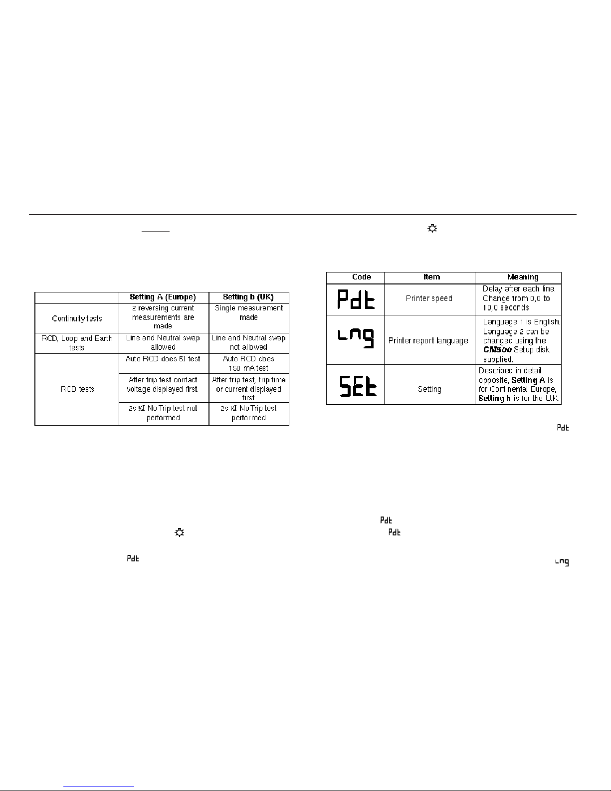
The
first line gives the setting, which modifies the way the
instrument behaves.
The second line gives the printer report language. This may be
Language 1, which is English, or Language 2 which is the
language noted on the third line of the label.
Instrument Setup
The instrument setup mode allows you to change the setting, the
printer speed and the printer report language.
To display the current setup modes:-
1. Press and hold the
backlight key, then turn the rotary
selector switch from the from ‘OFF’ position to the ‘RCL’
position. The code (printer speed) is displayed.
2. Release the
backlight key.
3. Toggle the
I key to scroll through and display the current
setup modes. as follows:-
To change the Printer speed
1. Toggle the I key to scroll through and display the
code.
2. Press the
SAVE key. The current speed setting is
displayed.
3. Toggle the
RCL keys until the required speed setting is
displayed.
4. To save the new setting, press the
SAVE key. The bleeper
sounds and is displayed. To abort the new setting, press
the
EXIT key. is displayed.
To select the Printer language
1. Toggle the I key to scroll through and display the
code.
Initial Setup
4
Page 5

2. Press the SAVE key. The current printer report language is
displayed as 1 (English) or 2 (as given on the type label on
the previous page).
Note:- Language 2 can be changed using the CM500 Setup
Disk supplied.
3. Toggle the
I key until the required language setting is
displayed.
4. To save the new setting, press the
SAVE key. The bleeper
sounds and is displayed. To abort the new setting,
press the
EXIT key. is displayed.
To select the Setting
1. Toggle the I key to scroll through and display the
code.
2. Press the
SAVE key. The current setting is displayed as A
(Continental Europe) or b (U.K.).
3. Toggle the I key until the required setting is displayed.
4. To save the new setting, press the
SAVE key. The bleeper
sounds and is displayed. To abort the new setting,
press the
EXIT key. is displayed.
CM500 Setup Disk
The program on the disk enables the second printer language to
be changed into any of the separate languages. The program
may be run directly from disk. Connect the PC to the instrument
via a serial lead.
for DOS type: a:\cm500set and press: Return.
for Windows™ 3.1 or 3.11:
1. From the Program Manager options, select: File
2. From the options given, select: Run.
3. Type:
a:\cm500set and press: Return.
For Windows™ 95:
1. Select the Start menu.
2. Select the
Run option.
3. Type:
a:\cm500set and press: Return.
Follow the instructions given by the program.
5
Page 6

The MEGGER CM500 Multi-function Installation Tester is a
compact instrument designed to perform all of the functions
required by the electrical contractor to fully test domestic,
commercial and industrial wiring. Specially designed to comply
with U.K., European and other International wiring regulations
and standards, the
CM500 may be used on all single and three
phase systems with rated voltages up to 300 Volts a.c. rms to
earth/ground.
Measured values are indicated on a large backlit analogue/digital
LCD and may also be stored in internal memory for later recall to
the display, direct printing via a standard serial printer, or
downloaded to a PC for storage, analysis and report generation.
The
CM500 is supplied as standard in a protective test and carry
case, and with the necessary mains plug lead and 2-wire lead set
required to commence testing. Optional accessories include the
SP2, a 2-wire lead set with test switch built into one of the probes
providing remote operation, and a 5 metre 2-wire lead set for
increased accessibility.
Key Features
•
No Trip loop Impedance test
• Storage of test results in memory
• Direct serial printer driver output
• RS-232 Output for PC storage
• Recall stored results to the display
• RCD Ramp test function
• Analogue arc and digital display.
• Selectable backlight
• Optional switchable probe (SP2)
Test Capability
• Insulation
Test voltages of 250V, 500V and 1000V.
• Continuity testing
Fast bleeper
Test lead resistance nulling
Automatic polarity reversal (
Setting A)
• Loop Testing
Operates regardless of mains polarity (Setting A)
Two wires only needed for testing
Automatic test start on voltage detection
Direct indication of short circuit current.
Phase - phase, phase - neutral & phase - earth tests
Simple earth electrode test
• RCD Tests
Tests selective (delayed) general and d.c. sensitive RCDs.
Two wires only needed for testing
Contact voltage and loop resistance displayed.
Selectable test current for programmable devices
• Supply voltage and frequency measurement
• Phase sequence indication
• Mains outlet polarity indication
Application
The CM500 may be be connected live to earth or between live
conductors of systems that have a rated voltage of 300V a.c. rms
to earth and an installation (overvoltage) Category
III or lower.
This means that the
CM500 may be connected to any fixed
wiring of a building installation, but not to primary supply circuits
such as overhead cables. To maintain user safety and ensure
accurate measurements, only use the test leads supplied or
General Description
6
Page 7
recommended for use with this instrument.
The
CM500 is fuse protected to 440V 10kA. The maximum
current which could flow through this fuse in the case of a fault is
limited to 10 kA by the impedance of the test leads. There is a
fuse accessible in the battery compartment which protects the
Insulation and Continuity range. If warning of a ruptured fuse is
given during a test, and if the warning symbol is present when
attempting to carry out an insulation test with the test leads
shorted together, this fuse must be replaced by another fuse of
the same type and rating i.e. 500 mA (F) 500 V H.B.C. 10 kA.
Fuse Replacement
To replace the fuse, disconnect the test leads, switch the
instrument Off and with a screwdriver, loosen the captive screw
holding the battery compartment cover in place. Remove the
cover. Depress the fuseholder slightly, and turn a quarter turn
anti-clockwise to release. Remove the holder and replace the
fuse with one of the correct size and rating. Relocate the fuse
holder, depress and turn a quarter turn clockwise. Replace and
re-secure the cover.
Battery Replacement
When the low battery symbol appears, the cells are nearly
exhausted and should be replaced as soon as possible. When
the battery is exhausted, the instrument will not perform tests
and the cells must be replaced. Use Alkaline cells IEC LR6 (AA)
or 1,5 V nickel cadmium cells only.
To install or replace the cells,
disconnect the test leads, switch
the instrument Off and loosen the captive screw holding the
battery compartment cover in place. Remove the cover, lift out
and disconnect the battery holder to access the cells. Ensure
that the replacement cells are fitted with the correct polarity, in
accordance with the symbols on the battery holder moulding.
Carefully re-connect the battery holder to the plug, replace the
battery holder in the compartment, and re-secure the cover.
Remove the cells if the instrument is not going to be used for any
extended period of time. Stored results are retained when the
battery is disconnected.
Test Leads
All test leads form part of the measuring circuit of the instrument
and must not be modified or changed in any way, or be used with
any other electrical instrument or appliance. The power cord
supplied with the
CM500 is a test lead that forms part of the
measuring circuit of the instrument. The overall length of this lead
must not be altered. If the power cord plug is not suitable for your
type of socket outlets, do not use an adaptor. You may change
the plug once only by cutting the cord as close to the plug as
possible and fitting a suitable plug.
The colour code of the cord is:
Earth (Ground) Yellow/Green
Neutral Blue
Phase (Line) Brown
Note:
A plug severed from the power cord must be destroyed, as
a plug with bare conductors is hazardous in a live socket outlet.
7
Incorrect battery cell polarity
can cause electrolyte leakage,
resulting in damage to the
instrument.
Page 8
8
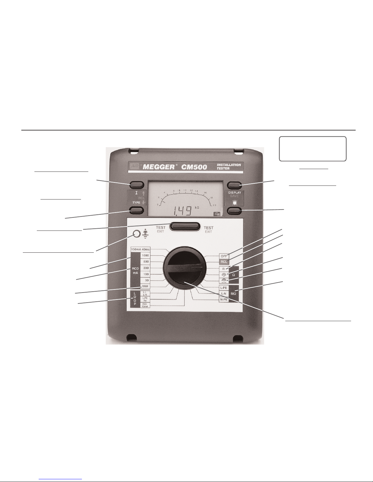
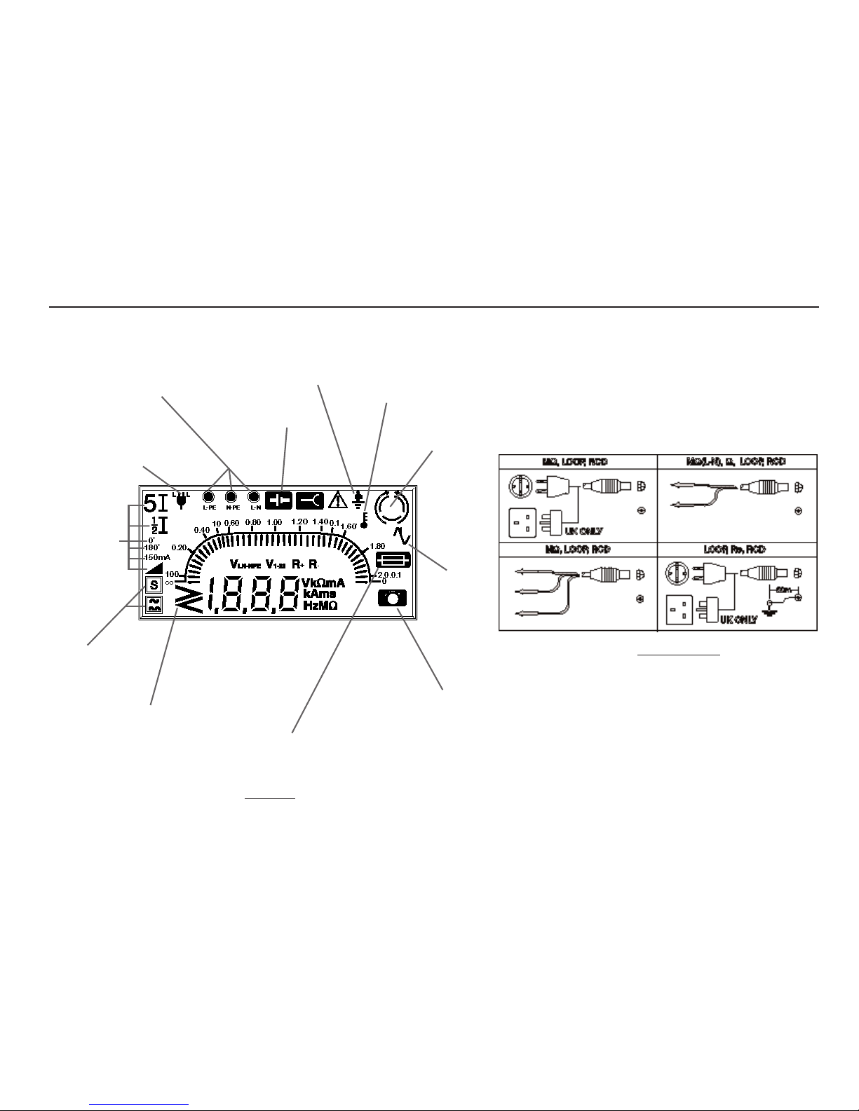
Features, Controls and Connections
Press I and TYPE key to:
• Select test parameters
• Enter test result identification
Auto Shut-off
Operates after 5 minutes of
inactivity by the instrument
(30 seconds in Bleeper mode)
Turn Rotary Selector Switch to:
• Select test position
• Select Download (RCL)
• Select ‘OFF’
Press TYPE key to:
• Select test voltage (MΩ)
• Select type of RCD
• Delete data (in combination
with
I key)
Insulation test positions
Continuity test position
VAR test selection
Push TEST
button to:
• Initiate the selected test
• Repeat selected test
Touch finger to Earth Test Pad to:
• Check potential between the Earth
connection and your finger
Press key to:
• Display other test results
Press and hold key to:
• Save test results
RCD test selection
Backlight key
Continuity Bleeper position
Lead resistance null
position
Recall / Download position
‘OFF’ position
150mA 40ms test selection
Loop test selection
Page 9
9
Fuse
Ruptured
Low Battery
voltage indication
3 Phase
sequence
RCD Test
Selection
RCD Type
Selection
Lead resistance
null ‘On’
Over / Under
Range
Excessive
Noise
Single Phase
Polarity indication
Plug polarity
Thermal
Trip operated
Touch button -
Earth >100 V.
CM500 Display
CM500 Connections
Page 10
Backlight
The display backlight gives a clear display of measurements in
poor lighting conditions. The backlight will briefly operate when
the
CM500 is switched on. To switch the backlight on, press the
key. Press the key again to switch the backlight off.
To conserve battery power, the backlight will automatically switch
off after a period of 15 seconds (if the battery voltage is low, this
period is automatically reduced).
Auto Shut - Off
To extend battery life and reduce unnecessary drainage, the
CM500 uses advanced battery management techniques,
switching functions off when they are not required. For example,
if an external voltage of 25 V or less is applied, no value is
displayed unless the backlight is switched on. After a period of
inactivity by the instrument, the
CM500 will switch itself off,
preceded by a series of bleeps. To switch the instrument back
on, press any key.
Switched Probe SP2
This is an accessory which can be used anywhere that the 2-wire
lead set is specified in this User Guide. The press button probe
duplicates the function of the
TEST key on the instrument,
allowing quick and easy testing.
Checking Earth Potential
To quickly distinguish live and earth, this feature provides display
indication if a voltage greater than 100 V exists between the
earth connection and your finger.
1. In any switch position except
OFF, RCL and (Ω) ,
connect the earth connection (black for the 2-wire lead
set, green for the 3-wire lead set) to earth.
2. Touch a finger to the metal pad on the front panel. This
is safe and will not endanger you.
3. If a voltage greater than 100 V exists between the finger
(normally at earth potential) and the earth wire, the
warning symbol is displayed.
Voltage and Frequency Measurement
The CM500 will display the supply voltage and frequency in all
switch positions except
(Ω) , RCL and OFF. The DISPLAY
key will alternate between voltage and frequency.
Power plug connection
1. Insert the power cord plug into an installation socket.
2. Supply voltage and polarity are displayed.
3. Press
DISPLAY to alternate between supply voltage and
frequency.
2-wire lead set connection
If an installation socket is not available, use the 2-wire lead set.
1. Connect the red and black leads to the two conductors to
be tested.
2. Voltage between the leads and polarity are displayed.
Note:- Though displayed, when using the 2-wire test set, ‘neon’
Operation
10
The SP2 probe test key circuit is hazardous live
during a test. It is safe in normal use.
Continuity of the
SP2 probe non replaceable fuse must be
confirmed (by testing in the Bleeper range) before making any
measurement.
Page 11
indication is invalid and should be ignored.
3. Press
DISPLAY to alternate between supply voltage
and frequency.
3-wire lead set connection
If an installation socket is not available and it is necessary to
connect to all three conductors, use the 3-wire lead set.
1. On a single phase system connect the red lead to phase,
the black to neutral and the green to earth.
2. Supply voltage and polarity are displayed.
3. Press
DISPLAY to alternate between supply voltage and
frequency.
Note: For connection to a three phase system, see
‘Determining Phase Sequence’.
When connected, the instrument will display the supply voltage
indicated in the following table:
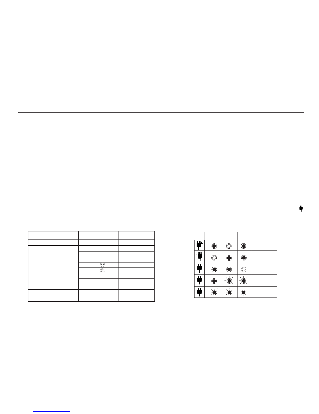
Polarity Indication
If connected to a single phase power supply by a plug or by the
3-wire lead set, three LCD ‘neons‘ marked
L-PE, N-PE and L-N
respectively will indicate supply polarity. If a voltage is detected
between their respective two wires, the ‘neon’(s) will activate. A
‘neon’ will usually flash if one connection is open circuit.
Note:- The presence of a voltage between phase and earth does
not prove earth continuity, as the earth could have a high
resistance and a voltage would still be measured. To test earth
continuity refer to the sections on loop resistance or RCD testing.
If
Setting A is set, the CM500 will automatically switch Line and
Neutral as appropriate, when in any of
LOOP, Re (earth) or RCD
test functions. This enables a test to be performed without
inverting the plug connections. The live terminal of the wall
socket is identified by the addition of a separate symbol
adjacent to the ’neons’. The Phase / Neutral reversal and symbol
display does not occur in Setting A Insulation and Continuity
ranges, and does not occur in Setting b.
Setting A - LOOP, Re (earth) and RCD
11
Mode
RCD Tests (all Currents)
Loop Resistance
Continuity
Insulation
Download to PC
Off
Switch Position
Voltage Display
L-PE
L-N
L-PE
L-PE
L-N
L-N
L-N
L-N
N-PE
No Display
Off
RCL
(MΩ
) L-N
(MΩ) N-PE
(MΩ
) L-PE
(Loop) L-PE/Re
(Ω) R
(Ω)
(Ω)
(Loop) L-L/L-N
(RCD) positions
Normal Supply
L-PE N-PE
L-N
L-N Reversed
Neutral Live
Neutral
Open Circuit
Earth
Open Circuit
Page 12
Operation (Contd.)
12
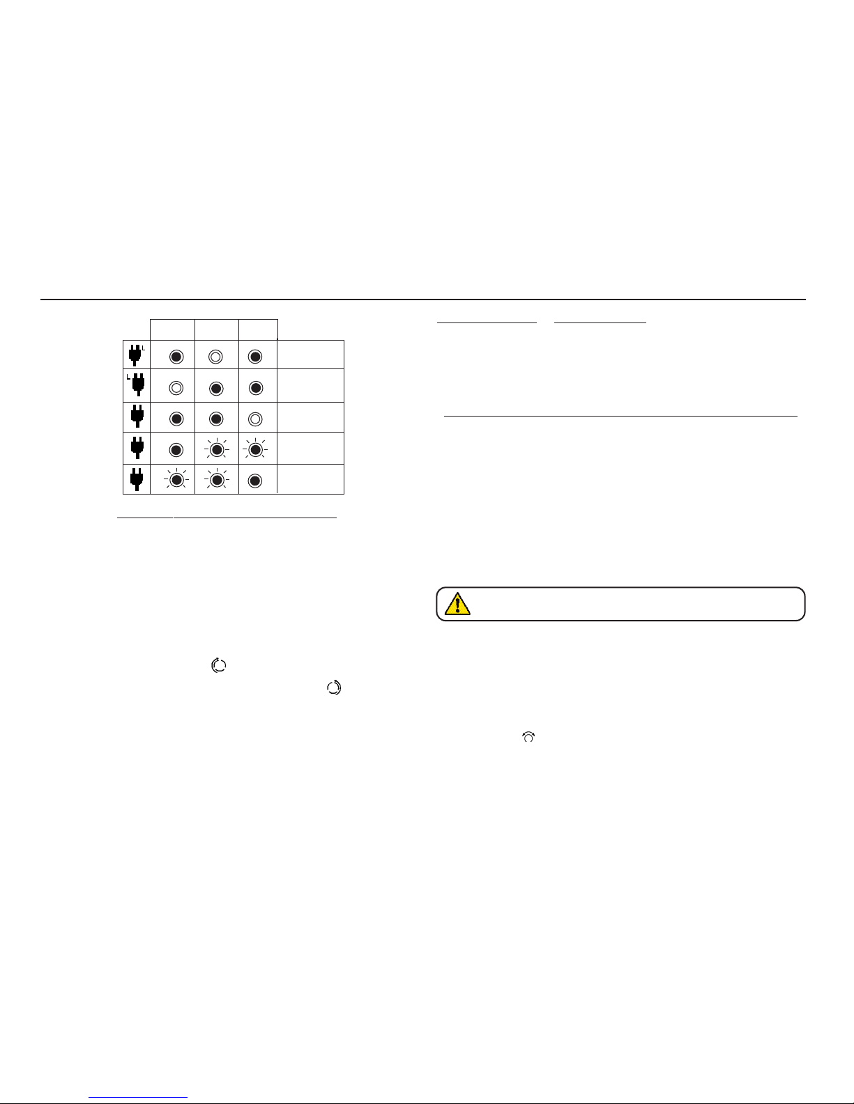
Setting A - MΩ and Ω, and Setting b
Determining Phase Sequence
When connected to all conductors of a three phase system, the
CM500 automatically displays the sequence of phase rotation.
Connect the
CM500 as follows:Line 1 Red phase Red lead
Line 2 Yellow phase Green lead
Line 3 Blue phase Black lead
If connected as above, the symbol is displayed when the
sequence is 1:2:3, or Red-Yellow-Blue. The symbol is
displayed when the sequence is 1:3:2, or Red-Blue-Yellow. If one
of the lines is faulty, neither of the symbols is displayed and the
normal ‘neon’ polarity indication is shown.
To measure the phase to phase voltages, the following switch
positions are used:-
Switch position Voltage Shown
(MΩ) L-PE Red and Green Leads V
1-2
(MΩ) L-N Red and Black leads V
1-3
(MΩ) N-PE Black and Green leads V
2-3
Continuity Testing, Low Resistance and kΩ Measurement
The CM500 will measure low resistance from 0.01Ω to 99.9Ω
and will automatically change range to kΩ up to 99.9 kΩ using
the 2-wire lead set. Up to 10 Ω of test lead resistance may be
subtracted using the test lead resistance nulling range.
Measurement is displayed on the large digital display, and the
analogue scale from 0 Ω to 20 Ω, or 0 to 20 kΩ.
In
Setting A, automatic polarity reversal is carried out with the
CM500 measuring resistance with both positive and negative
current flow. Normally the average of the two results will be
displayed.
Test Lead Resistance Nulling
The CM500 measures total resistance between its terminals,
including the resistance of the test leads. The value of the test
leads can be automatically nulled.
1. Firmly short the ends of the test leads together.
2. Select (Ω) lead resistance null position.
3. Press the
TEST key. The test leads are checked.
4.
0.00 Ω is displayed to confirm that a new lead value has
been stored.
CM500 will automatically display any voltage over 25 V
between the two test leads, and inhibit testing if >5 V.
Normal Supply
L-PE N-PE
L-N
Normal Supply
Neutral Live
Neutral
Open Circuit
Earth
Open Circuit
Page 13

This measured lead resistance will be subtracted from all
subsequent continuity tests in the (Ω) R switch position. Note that
this lead nulling will not be lost when the instrument is switched
off.
To clear any set nulling, carry out a lead resistance nulling
procedure with the leads open circuit.
Low Resistance continuity measurement (Ω) R
1. If required, firmly short test leads together and null their
resistance as described above.
2. Select
(Ω) R.
3. Firmly connect the two wire lead set terminals across the
isolated circuit.
4. Press the
TEST key. The test result is displayed. The
symbol is displayed if lead resistance nulling has been
set.
Continuity Bleeper (Ω)
To quickly check continuity of a circuit, the CM500 bleeper will
sound continuously if the resistance between the leads is less
than 100 Ω.
Low input resistance voltmeter (Ω
)
In switch positions other than Continuity Bleeper, the supply
voltage is measured with a high input resistance. This can cause
misleading readings if cables are open circuit. In the Continuity
Bleeper
position, the input resistance is initially about 1 kΩ
. If
external voltage is measured at the terminals, the bleeper
sounds with a slow intermittent tone, and displays the voltage.
This will not damage the instrument, however thermal protective
devices will inhibit immediate use of the Continuity bleeper, for a
short period. If the ‘hot’ symbol is displayed, confirm the
bleeper operation by shorting the test leads and waiting for the
normal continuous bleeper tone.
5Ω Threshold
A lower threshold of 5 Ω can be set by pressing the TEST button.
When this is set, the bleeper will sound with a fast intermittent
tone if the resistance between the leads is between 100 Ω and
5 Ω, and continuously if the resistance is less than 5 Ω. When set
to this mode, the 500 mA fuse is used to protect the instrument
and may be ruptured by connection to a mains supply.
Method of measurement
The 2-wire lead set must be used for this measurement. A d.c.
voltage of nominally 4,5 V with a current limit of approximately
210 mA is used to measure resistance less than about 30 Ω.
Higher resistances are measured with a current limit of 2 mA.
The first measurement is made with current flowing from the
black lead to the red lead, and if
Setting A has been set, a
second measurement will be made with the current reversed.
Possible sources of error
Measurement results can be affected by the following:
• The impedance of operating circuits connected in
parallel.
• Impedance such as inductors that vary during the
measurement.
• A poor connection to the circuit under test, which can
give readings as much as 100 mΩ (0,10 Ω) high. The
best way to avoid this error is to use sharp prods and
press these firmly into the conductors being
measured.
13
Page 14

Insulation Testing and High Resistance Measurement
The CM500 will test insulation resistance (1 kΩ to 99.9 MΩ)
between phase, neutral and earth (ground) as required, at the
selected voltage. With a default setting of 500 V d.c., the test
voltage can be altered to 250 V, 500 V or 1 kV as required.
Measurement is displayed on the large digital display and the
analogue scale.
2-wire lead set method
1. Disconnect Phase, Neutral and Earth at the distribution
board.
2. Connect the leads across the isolated circuit.
3. Select
(MΩ) L-N.
4. Press either the
I or the TYPE key to display the test
voltage. Press again until the required test voltage is
displayed.
5. Press and hold the
TEST key.
6. Circuit resistance value is displayed.
7. Release the
TEST key, but maintain connection to allow
the test voltage to discharge.
3-wire lead set method
Use of a 3-wire lead set enables all combinations of insulation to
be tested without changing lead connections.
1. Disconnect Phase, Neutral and Earth from the distribution
board.
2. Connect the red lead to Phase; the black lead to Neutral,
and the green lead to Earth (ground).
3. Select
(MΩ) L-PE, L-N or N-PE as required.
4. Press either the
I or the TYPE key to display the test
voltage. Press again until the required test voltage is
displayed.
5. Press and hold the
TEST key.
6. Circuit resistance value is displayed.
7. Release the
TEST button, but maintain connection to allow
the test voltage to discharge.
Power plug method
The insulation resistance of an installation may be tested by
using the plug terminated test lead at a convenient socket
outlet. However:-
a) The installation must be isolated from the supply.
b) The insulation test will incorporate the immediate
circuit and any other circuit connected on the load side
of the distribution board (D.B.).
c) If a low reading is obtained, each circuit must be
individually tested from the distribution board to locate
the fault.
Operation (Contd.)
14
After performing an insulation test, maintain
connection to the circuit under test to allow the circuit to
discharge. If voltage remains after a test, the
CM500
will normally display this as it is discharged. It must be
verified that the test voltage has been discharged
before moving onto the next test.
When using the 2-wire lead set to measure
insulation, always select (
MΩ) L-N. The insulation
will be measured between the two leads.
Page 15

1. Disconnect Phase, Neutral and Earth from the D.B.
2. Insert the power plug into an installation socket on the
isolated circuit to be tested.
3. Select (
MΩ) L-PE, L-N or N-PE as required.
4. Press either the
I or the TYPE key to display the test
voltage. Press again until the required test voltage is
displayed.
5. Press and hold the
TEST key.
6. Circuit resistance value is displayed.
7. Release the
TEST button, but maintain connection to allow
the test voltage to discharge.
Method of measurement
A current limited d.c. source is used, and the resistance is
calculated from measurements of the voltage and current. The
polarity of this d.c. source is as follows:-
Range +ve terminal -ve terminal
L-N Neutral (Black) Phase (Red)
N-E Neutral Earth
L-E Phase (Red) Earth (Black)
The voltage is only present when the test button is pressed. A
measurement of the terminal voltage is made before the test and
if this exceeds about 25 V the test is disabled. If d.c. voltage is
detected across any of the terminals a discharge resistor is
connected across it. The reading is stable with a circuit
capacitance less than 5 µF.
Loop Impedance measurement
Loop impedance measurement of 0,01Ω up to 3.00 kΩ can be
made via installation sockets using the plug terminated test lead,
or at any other convenient point on the installation using the two
wire lead set. If
Setting A is selected when using the plug
terminated lead set, the polarity of the mains socket is
immaterial. Line and Neutral will be swapped if necessary, and
an indication given on the display.
Setting b requires Line and
Neutral to be fixed.
The
CM500 will measure the loop resistance from the supply
end of the standard test leads, allowing for their resistance.
15
Test results may be adversely affected by supply voltage
fluctuations or electrical ‘noise’ during measurement. It is
recommended that tests are repeated and the results verified,
if measurement results are considered abnormal.
V
O
L
T
S
RESISTANCE - MΩ
1000 V
500 V
250 V
Insulation T
est Voltage
Page 16

Phase to Neutral or Earth loop impedance measurement Power plug method
1. Select (Loop) L-PE or L-N as required.
2. Insert the plug into an installation socket.
3. Supply voltage and polarity are displayed.
4. Press the
TEST key.
5. Measured loop value is displayed.
On completion of this test, prospective fault current can be
displayed by pressing the
DISPLAY key.
If desired the test can be repeated by pressing
TEST again.
Phase-Earth loop impedance measurement-Two wire method
If an installation socket is not available, use the the 2-wire lead set.
1. Select
(Loop) L-PE.
2. Connect the red lead to phase and the black lead
to earth. No connection to neutral is required.
3. Supply voltage is displayed.
Note:- Though displayed,
polarity indications are invalid with the two wire lead set
and should be ignored
4. Press the
TEST key.
5. Measured loop value is displayed.
On completion of this test, prospective fault current can be
displayed by pressing the
DISPLAY key.
If desired the test can be repeated by pressing
TEST again.
Bonded Metalwork Testing (1)
This test is performed using the two wire lead set.
1. Connect the black lead to the bonded metalwork.
2. Connect the red lead to phase.
3. Select (
Loop) L-PE
4. Supply voltage is displayed.
5. Press the
TEST key.
6. Measured resistance value is displayed.
Bonded Metalwork Testing (2)
This test can also be performed using the optional earth bond
test lead, allowing connection to an installation socket.
1. Connect the black flying test lead to the bonded metalwork.
2. Insert the power plug test lead into a socket (receptacle).
3. Select
(Loop) L-PE.
4. Supply voltage is displayed.
5. Press the
TEST key.
6. Measured resistance value is displayed.
Operation (Contd).
16
Automatic testing
To aid rapid testing, the CM500 can be set to start a test
automatically when connected to the supply. This may be of
use, for example, when using a clip and a probe. Select the
range required and press the test key without the supply
present. The instrument will display
<100 V for approximately
30 seconds. Apply the supply voltage within this time and the
instrument will pause before performing one test
automatically.
Page 17

Prospective Short Circuit Current measurement (PSCC)
The PSCC of a circuit is the largest Prospective Fault Current
(PFC). In a single phase system, this would be the larger of the
earth loop PFC and the neutral loop PFC. In a multi-phase
system phase-phase loops also need to be considered and these
can be measured using the
(Loop) L-L switch position.
When
CM500 measures the loop resistance, it also calculates
the PFC. After any loop test, this may be displayed by pressing
the
DISPLAY key.
The PFC is calculated by using the sum:-
Nominal supply voltage
Loop resistance
The nominal supply voltage depends on the actual measured
voltage and the configuration of the instrument. As supplied, the
CM500 is configured as follows:-
PFC measurement accuracy
An accurate PFC measurement requires an accurate
measurement of the loop resistance. The difference of a few
digits in the loop resistance measured will have a large effect on
the PFC displayed.
Errors can be reduced by:-
• Using the 2 wire lead set with prods and making a firm
connection to clean conductors.
• Making several tests and taking the average.
• Ensuring that potential sources of noise in the
installation are isolated (switched off).
• Ensuring that the instrument is calibrated.
Earth Loop Resistance measurement at 15 mA
The LOOP 2 kΩ 15 mA range is a high resolution, low current
resistance range. The 15 mA current enables the earth loop
resistance to be measured without tripping all types of RCDs with
a rated current of 30 mA or higher. Tests may be made via
installation sockets with the plug terminated test lead, or at any
other point using the 2-wire lead set. Connections are required to
Line and Earth only.
15 mA - Phase to Neutral or Earth loop impedance
measurement - Power plug method
1. Select (Loop) 2kΩ 15mA.
2. Insert the plug into an installation socket.
3. Supply voltage and polarity are displayed.
4. Press the
TEST key. Test progress is displayed.
5. Measured loop value is displayed
If desired the test can be repeated by pressing
TEST again.
15 mA - Phase-Earth loop impedance measurement -2-wire
method
1. Select (Loop) 2 kΩ 15 mA.
2. Firmly connect the red lead to phase and the black lead
to earth. No connection to neutral is required.
17
Actual measured Voltage
150 V
>150 V and <300 V
>300 V
Nominal Voltage
110 V
230 V
400 V
Page 18

3. Supply voltage is displayed.
Note:- Though displayed, polarity indications are invalid with
the 2- wire lead set and should be ignored
4. Press the
TEST key. Test progress is displayed.
5. Measured loop value is displayed.
If desired the test can be repeated by pressing
TEST again.
Method of measurement
The phase-earth, phase-neutral or phase-phase loop resistance
can be measured. The instrument takes a current from the
supply and measures the difference between the unloaded and
loaded supply voltages. From this difference it is possible to
measure the loop resistance. The test current will vary from 15
mA to 40 A, depending on supply voltage and the loop resistance
value. The test duration will depend on the loop resistance value.
Possible sources of error
The reading depends on a measurement of the supply voltage
and therefore noise or transients caused by other equipment
during the test could cause an error in the reading. One way to
check for these is to do two tests and look for any difference in
value. The instrument will detect some sources of noise and
warn the user, where other instruments may give an incorrect
reading. Any leakage current as a consequence of other
appliances connected to the supply under test may affect the
reading. If the Phase - Earth loop is being measured, this
leakage may be due to filter capacitors etc.
RCD Testing
The CM500 can test the operation of a variety of types of
Residual Current Devices (RCD), measure the phase to earth
loop resistance, and the contact voltage of the installation. Using
an earth test spike, the earth resistance and fault voltage may be
measured. If
Setting A is selected when using the plug
terminated lead set, the polarity of the mains socket is
immaterial. Line and Neutral will be swapped if necessary, and
an indication given on the display.
Setting b requires Line and
Neutral to be fixed.
Pre-Test Configuration
Before performing an RCD test it is necessary to ensure that the
CM500 is correctly configured for the rated current and the
specific
type of RCD to be tested, and for the type of test to be
performed.
RCD Current Rating
From information given on the RCD to be tested, select the RCD
current rating on the rotary switch.
RCD VAR switch position
This position enables any RCD with a non standard rated current
between 10 mA and 1000 mA to be tested. The test is performed
at the selected current, taking the 5I multiplier into consideration
1. Select
(RCD) VAR.
2. Toggle the
DISPLAY key to display the test current.
3. Press the (
×) RCL keys until the required test current is
displayed. Hold a key down to auto-repeat.
4. Press the
DISPLAY key. The Supply Voltage, Test Type
and RCD type are shown. These may be set up as given
in the following sections.
Operation (Contd.)
18
Page 19

Setting precision:- 10 - 50 mA 1 mA steps
50 - 500 mA 5 mA steps
500 mA - 1000 mA 10 mA steps
RCD Type
Pressing the TYPE key displays the RCD type symbols. From
information given on the RCD to be tested, select and set the
type of RCD.
D.C. Sensitive relays
Some RCDs are electromechanical devices which can be
saturated by the presence of d.c. Therefore if a d.c. fault occurs,
or an a.c. fault occurs in the presence of quite a small direct
current, the RCD may not trip. In this way the RCD is disabled
and this becomes a potential hazard. Because of this, ‘d.c.
sensitive’ RCDs are available.
Selective or Time delayed RCDs
In some cases it may be necessary to have an RCD protecting
an individual circuit or group of circuits. If a fault occurs, the RCD
nearest to the fault should trip to clear it, maintaining supplies to
the other circuits. Selective RCDs (normal symbol )are used to
discriminate faults occurring on separate circuits, and these have
a minimum as well as a maximum trip time.
Type of test
19
Symbol
Test
General
Selective (delayed)
D.C. Sensitive
Display
1
⁄2I
0˚
180˚
5
I
Type of Test
No Trip
Trip Test
Trip test
Ramp test
Trip Test
Description
Performs a no-trip test at half the
rated current of the selected RCD.
The test measures the earth loop
resistance and contact voltage, or
with a test spike, the earth
resistance and fault voltage.
Trip test at the rated current of the
selected RCD. A
1
⁄2I test is carried
out before this, and the resistance
and voltage are available after the
test. The test is always started on a
zero crossing when the
instantaneous voltage is on the rise.
As above, but the test is always
started on a zero crossing when the
voltage is on the fall.
Test current increases from half the
rated current of the RCD. The result is
the current at which the trip opens.
Trip test at 5 X the rated current of
the selected RCD. The choice of 0˚
or 180˚ gives greater accuracy of
measurement.A
1
⁄2I test is carried
out before this, and the resistance
and voltage are available after the
test.
Ramp and Auto sequence tests are only available if
the test current is set to 10 mA. The maximum possible
test current (including
5I multiplier) is 1000 mA (300 mA
for d.c. sensitive RCDs). These limits are halved if the
supply voltage is less than 200 V.
Page 20

Pressing the I key displays the Type of Test symbols individually
in sequence. Select the type of the test to be performed.
No Trip Tests
When an 1⁄2I (or No Trip) test is performed, the loop or earth
resistance is measured, and in
Setting b a two second No Trip
test follows.
Loop or Earth resistance measurement
The loop resistance is measured at half the rated RCD current
selected. Contact voltage is displayed which is the loop
resistance multiplied by the rated RCD current. A high loop
resistance will cause the
CM500 to display >90 V, and safely
abort the test.
The earth resistance is measured if a lead is connected into
socket [S] on the top of the instrument. Refer to ‘Earth
Resistance Measurement’ for correct positioning of the earth
test spike. The earth test gives the resistance of the local spike,
whereas the loop test will give the entire Line-Earth loop
resistance value.
2 second ‘No Trip’ test (Setting b only)
A requirement of the IEE regulations is that half the rated
operating current of the RCD is drawn for 2 seconds, and the
RCD must not trip. Tripping of the RCD will indicate that it is over
sensitive, or that excessive earth leakage current is being drawn
in the system. The load put onto the circuit is resistive and
therefore the test current is sinusoidal if the supply is sinusoidal.
No Trip testing
The test is the same for all RCD types. Select the Rated
Current, the RCD Type and 1⁄2I. Connect to the installation and
press the TEST key. If the settings are correct, and the RCD is in
order, the RCD trip should not
operate and the Contact or Fault
voltage will be displayed. If the RCD trip does operate during the
test, the message is displayed. This could be due to incorrect
current
rating selection, excessive leakage current in the circuit, or a
faulty RCD. If the problem is excessive leakage current, the
source of the problem must be located and rectified before a trip
test is performed, otherwise the result of the trip test will be
invalid. Earth or loop resistance can be shown by pressing the
DISPLAY key.
Trip Tests
The instrument will measure the trip time or trip current of
common, selective (time delayed) and d.c. sensitive RCDs. The
trip time is measured by timing the period from the application of
a resistive load to when the supply fails.
Some RCDs are sensitive to the polarity of the supply, i.e.
whether the test current is applied with the instantaneous rising
or falling. Tests should therefore be performed with the polarity 0˚
and 180˚ and the maximum time taken.
D.C. sensitive RCDs are tested with a pulsed waveform. The rms
current is √2 x the rated operating current of the RCD. As with the
normal RCDs, these should be tested with 0˚ and 180˚ polarity.
As the No Trip test can affect the trip time of some selective
RCDs, there is a 30 second delay before activation of the trip
test. It is possible to override this delay by pressing the
TEST
button when the instrument is counting (1...2...3...).
Note:- Significant operating errors can occur if loads, particularly
rotating machinery and capacitive loads are left connected
during tests.
Operation (Contd.)
20
Page 21

21
† For supply voltages above 200 V only.
Trip Testing (measuring the trip time)
1. Select the RCD rated current on the rotary switch.
2. Connect to the supply as detailed below.
3. Select the required test using the
I key - 0˚ or 180˚ for the
normal trip tests, or
5I together with 0˚ or 180˚ for a 5I
test.
4. Select the
RCD type using the TYPE key.
5. Press the
TEST button.
If the RCD trips, the first display depends upon the Setting
selected.
Setting A: The contact or fault voltage is displayed with
the Loop or earth resistance and trip time available by pressing
the
DISPLAY key. Setting b: The trip time is displayed with the
contact/fault voltage and Loop/earth resistance available by
pressing the DISPLAY key.
150 mA 40 ms test
When an RCD is fitted for personal protection, a test current of
150 mA must cause the RCD to trip in less than 40 ms.
1. Select the 150 mA 40 ms rotary switch.
2. Connect to the supply as detailed below.
3. Select and set the Trip Test to 0˚ or 180˚ using the
I key.
4. Press the
TEST key.
If the RCD trips within 40 ms, the trip time is displayed.
Ramp Test (measuring the trip current)
The trip current is measured by applying a test current of half the
rated trip current and increasing this every 200 ms. When the
supply is cut, the current flowing is recorded and displayed.
A low trip current could be due to an overly sensitive RCD, or to
leakage currents in the supply.
To determine the trip current of an RCD.
1. Select an appropriate RCD rated current on the rotary
switch.
RCD rating
D.C. sensitive
RMS currents
10mA 14,1 mA
30mA 42,4 mA
100mA 141 mA
300mA 424 mA
†
500mA Not available
1000mA Not available
RCD rating Current Range Step Value
10mA 5..15mA 1 mA
30mA 15..50mA 1 mA
100mA 50..150mA 2 mA
300mA 150..300mA 6 mA
500mA 250..500mA 10 mA
1000mA 500..1040mA 52 mA
Page 22

2. Connect to the supply as detailed on the next page.
3. Select the Ramp test using the
I key.
4. Select the RCD type using the
TYPE key.
5. Press and hold the
TEST button.
If the RCD trips, the first displayed result depends upon the
Setting selected.
Setting A: The contact or fault voltage is displayed with the Loop
or earth resistance, trip current and trip resistance available by
pressing the
DISPLAY key.
Setting b: The trip current is displayed with the trip resistance,
contact/fault voltage and loop/earth resistance available by
pressing the
DISPLAY key.
The Trip current and the Trip resistance values are displayed
with both the 0˚ and the 180˚ symbols. The Trip resistance is the
fault required to trip the RCD.
Auto Sequence RCD Test
If the RCD is not located near a convenient installation socket, it
could mean walking back and forward between the RCD and the
instrument to reset the RCD each time it trips out. To simplify and
speed up sequence testing, CM500 can be set to automatically
perform each subsequent test in the sequence each time that the
power is restored. This test depends upon whether
Setting A or
Setting b is selected. The Overcurrent or Fast Trip is 150 mA
if
Setting b is selected, and 5I if Setting A is selected. The
display shows
150 mA or 5I symbols as appropriate.The test
procedure is as follows:-
1. Connect to the supply as detailed on the next page.
2. Select the RCD rated current on the rotary switch.
3. Select Auto RCD test sequence by pressing the I key until
the
1
⁄2I; 0˚; 180˚ and Fast trip symbols are all displayed
together. Auto test is only applicable to a.c. sensitive non
delayed RCDs, therefore
Type segments are not
displayed.
4. Press and release the
TEST button.
5. Reset the RCD within 30 seconds after each trip test.
6. Tests will be carried out in the sequence
1
⁄2I, 0˚, 180˚,
Fast Trip 0˚ and 180˚. After each trip test, CM500 will wait
for up to 30 seconds for the supply to be switched back on
before continuing with the next test. The test sequence will
abort if any of the tests fail, or if the RCD is not reset within
the time limit.
On completion, the result of the last Fast trip test is displayed.
Press the
DISPLAY key to sequentially display:-
- Supply voltage
- Supply Frequency
- Contact/Fault voltage
- Earth Loop/Earth Resistance
- 0˚ trip test time
- 180˚ trip test time
- 0˚ Fast trip test time
- 180˚ Fast trip test time
All results can be stored under a single circuit reference. See
'
Test Result Storage, Deletion and Retrieval'.
Operation (Contd.)
22
Page 23

23
Connecting to the Supply
Power plug method
The simplest way of connecting to the installation is by inserting
the power plug into a convenient installation socket. If Setting A
is selected when using the plug terminated lead set, the polarity
of the mains socket is immaterial. Line and Neutral will be
swapped if necessary, and an indication given on the display.
Setting b requires Line and Neutral to be fixed.
1. Insert the power plug into an installation socket.
2. Select and set the rated current, RCD type and the test
type.
3. Supply voltage, configuration symbols and polarity are
displayed.
4. Press the
TEST key.
5. See previous notes for
Type of test
.
If desired the test can be repeated by pressing
TEST again.
2-wire lead set method
If an installation socket is not available use the 2-wire lead set.
1. Connect the red lead to phase and the black lead to earth.
No connection to neutral is made.
2. Select and set the
rated current, RCD type and the test
type.
3. Supply voltage and polarity are displayed prior to the test.
Note: Though displayed, polarity indication with the 2-wire lead
set is invalid and should be ignored.
4. Press the
TEST key.
5. See previous notes for
Type
of test.
If desired the test can be repeated by pressing
TEST key again.
Automatic testing
To aid rapid testing, the CM500 can be set to start a test
automatically when connected to the supply. This may be of
use, for example, when using a clip and a probe. Select the
range required and press the test key without the supply
present. The instrument will display
<100 V for approximately
30 seconds. Apply the supply voltage within this time and the
instrument will pause before performing one test
automatically.
Page 24

Earth Resistance Measurement
The CM500 can rapidly measure the earth electrode resistance
and earth resistance (from 0.01 Ω to 3.00 kΩ) of a TT installation
using the earth test spike and the plug terminated test lead, or at
any other convenient point on the installation using the 2-wire
lead set. If
Setting A is selected when using the plug terminated
lead set, the polarity of the mains socket is immaterial. Line and
Neutral will be swapped if necessary, and an indication given on
the display.
Setting b requires Line and Neutral to be fixed.
Inserting the Earth Test spike
A test spike must be inserted into the ground well away (>20 m)
from the main earth electrode(s) or anything connected to the earth
electrode(s). Buried earthed metal pipes, fences, etc. near to the
spike could give a misleading low reading. The
CM500 may
display ‘
E32’ or a very low resistance if the spike is incorrectly
positioned.To check the result, reposition the spike and verify the
readings. Suitable test spikes and leads are contained in the
accessory Earth Test Kit.
Earth resistance measurement - Power plug method
The earth resistance of an installation will include the effects of
any parallel resistance paths from the
PE conductor to earth e.g.
cross bonded metal service pipes.
1. Insert the test spike.
2. Connect the 20 m earth test lead to the
CM500 [4 mm
socket (S)] first and then to the test spike.
3. Select
Re.
4. Insert the power plug into an installation socket.
5. Supply voltage and polarity are displayed.
6. Press the
TEST key.
7. Measured earth resistance value is displayed.
Earth resistance measurement - 2- wire lead set method
1. Insert the Test spike.
2. Connect the 20 m earth test lead to the
CM500 [4 mm
socket (S)] first and then to the test spike.
3. Select
Re.
4. Connect the red lead to phase and the black lead to earth.
No connection to neutral is necessary.
5. Supply voltage is displayed.
Note:- Though displayed,
polarity indications are invalid when using the 2-wire test
lead set, and should be ignored.
6. Press the TEST key
7. Measured earth resistance value is displayed.
Earth Electrode Resistance Measurement
To measure the earth electrode resistance, the earth electrode
must be disconnected from the
PE conductor of the installation
under test. To do this safely, the installation must be switched Off
and isolated from the supply.
1. Insert the test spike.
2. Connect the 20 m earth test lead to the
CM500 [4 mm
socket (
S)] first and then to the test spike.
Operation (Contd.)
24
CM500 is calibrated to give the resistance from the
supply ends of the test leads. Test results may be
adversely affected by supply voltage fluctuations or
electrical ‘noise’ during measurement. It is
recommended that tests are repeated and the results
verified, when measurement results are considered
abnormal. Connect the test lead to the instrument first
and then to the earth spike.
Page 25

3. Switch Off and isolate the installation under test.
4. Disconnect the earth electrode.
5. Using the 2-wire lead set, connect the black lead to the
earth electrode under test.
6. Select
Re.
7. Carefully connect the red lead to the phase conductor
of the incoming mains supply on the distribution board.
8. Supply voltage and polarity are displayed.
9. Press the
TEST button.
10. Measured earth resistance value is displayed.
Note:- Though displayed, polarity indications are invalid using
the 2-wire test lead set, and should be ignored.
11. Disconnect the red and black leads. Switch off the
CM500.
12. Firmly re-connect the earth electrode.
13. Carry out a continuity test between the
PE conductor and
the earth electrode and confirm that a valid connection has
been made.
14. Switch on the supply.
15. Carry out a loop resistance test.
Method of measurement
The earth resistance is measured by taking a current from the
supply and injecting it into the resistance to be measured. The
voltage change across the earth resistance is measured by the
use of a remote probe 20-30 m away from any earth electrodes.
The test current will vary from 15 mA to 25 A, depending on
supply voltage and the loop resistance value. The test duration
will depend on the loop resistance value.
Possible sources of error
As with the loop resistance measurements, the reading depends
on a measurement of the supply voltage and therefore noise or
transients caused by other equipment during the test could
cause an error in the reading. One way to check for these is to
do two tests and look for any difference in value. The instrument
will detect some sources of noise and warn the user where some
instruments may have given an incorrect reading.
The measurement depends on the position of the probe. The
probe must be positioned away from any part of the installation
under test, so that it provides a valid reference earth. For a single
earth electrode, the distance of 20 m is found to be sufficient. Be
careful of secondary earth paths, such as service pipes. The best
way to confirm the measurement is to try two probe positions.
25
Page 26

26
Condition and Warning Indication
Error Numbers
Any hardware or software faults and errors will cause the
display to show an error number in the form of a digital ‘ ‘
together with an identifying 2 digit number.
If such an error number is displayed, switch the instrument ‘
Off’
and back ‘
On’ again. Then repeat the test that was originally
being carried out, or as given in the following table.
If the error number is again displayed, switch the instrument to
‘Off’, and return the instrument to the manufacturer for service,
together with a description of the events leading to the
message display. See ‘
Returning an instrument for Repair’
on page 39.
Error Number Appropriate Action
EEPROM failure. Stored data is
lost. Attempt to delete the stored
test results and then store
another result. If Error Number
persists, return the instrument for
service.
(
Loop LE, LN or LL) Secondary
internal thermal cut-out is open
circuit. Return the instrument for
service.
(
Re) May be due to incorrectly
positioned spike.
(
Earth, Loop, or RCD) Possibly
due to excessive ‘noise’ on the
supply, or the RCD unexpectedly
trips together with an internal
fault. If Error number persists,
return the instrument for service.
Condition
System Error
Low Battery
Touch Pad
>100 V
Supply voltage and
Freq. out of range.
Thermal Trip
Operated.
Supply interrupted
during test.
Noise.
Auxiliary spike
R. too high.
Earth test Spike
Voltage too high.
Auxiliary Spike
Fuse Ruptured.
Memory full
Memory
Corrupted
Cause
Hardware or software
fault.
Battery voltage too low.
Earth voltage too high.
Supply voltage or freq.
too high or low for test.
Too rapid testing with
no pauses for
heat dissipation
RCD Tripped.
or
Supply Failure
Excessive external
supply noise during
earth loop or RCD test.
Incorrect connection.
Standing V. on probe
too high prior to test.
Spike connected.
No external d.c. V. and
I during insulation test.
Results memory full.
Results memory
unintelligible
Display
Action
Switch ‘Off’, then ‘On’
and attempt re-test.
Replace battery
Check installation or
wiring to
CM500
_
Pause between tests to
allow cooling.
Confirm RCD rating
and check for excess
earth leakage current
Identify and rectify,
or wait and re-test.
Rectify or re-position
auxiliary spike
Rectify or re-position
auxiliary spike
As required
Replace fuse.
(see page 7)
Download results and
clear memory
Press Test to
attempt recovery
> or <
and limit
value
>50kΩ
and
>20V
and
Page 27

27
Test Result Storage, Deletion and Retrieval
Saving Results
After a test, the result is displayed on the screen and this may be
saved with additional information. A circuit number (1 - 99) may
be assigned, and when moving site or building, circuits may be
grouped using the distribution board feature. In this way, when
downloading to
AVO PowerSuite, the results can be easily split
into different test schedules. When the results are displayed or
printed, a change in the distribution board is indicated.
Changing Distribution Boards (DB)
Before a test the distribution board number may be changed as
follows:-
1. Move the rotary selector switch to the
RCL position. The
code rcl is displayed.
2. Press the
SAVE key. The currently selected DB code is
displayed, e.g.
d01.
3. This number may be changed using the
× RCL keys to
display the required number.
4. The number can be accepted by pressing the
SAVE key,
or the procedure aborted by pressing the
EXIT key,.
5. When the number is saved the code
Std is displayed
(accompanied by a long bleep) to confirm that the data has
been saved.
Testing may now continue with all subsequent results associated
with the new distribution board number.
Saving a result
On completion and display of the measurement:-
1. Press and hold the
SAVE key. After about 1 second, a
bleep will be heard. For a
Continuity, (MΩ) L-N or (Loop)
L-N
test, a code, as given in the following table is
displayed. This code is used to describe the circuit tested
and can accordingly be modified by the user. For all other
tests, a circuit number code is displayed, and you should
proceed directly to step 4.
2. The code may be changed by pressing the
× RCL keys.
3. The code may be accepted by pressing the
SAVE key, or
aborted by pressing the
EXIT key.
4. The circuit number is displayed as 2 digits e.g.
c01.
Test to be saved
Display code
Meaning
Continuity
Insulation
Loop
Single circuit
Single circuit
R1 + R2 Return circuit
N - PE
L - N
L- L
L - PE
L - N
L - PE
L- L
Single circuit
Page 28

Note:- Many different tests may be saved under the same
circuit number.
5. The circuit number may be changed by pressing the
× RCL
keys to display an appropriate number. Hold the key down
to step through the circuit numbers.
6. The number can be accepted and the results saved by
pressing the
SAVE key, or the procedure aborted by
pressing the EXIT key.
7. When the result is saved, the code
Std is displayed
(accompanied by a long bleep) to confirm that the data has
been saved. The display of indicates that there is no
more test storage.
Delete all data
1. Move the rotary selector switch to the RCL position. The
code rcl is displayed.
2. Press the
× RCL keys together. The code dEL is displayed.
3. Confirm that the data is no longer required by pressing
the
SAVE key or abort by pressing any other key. The
code rcl is displayed.
Clear data and re-set factory default settings
The CM500 will remember certain values such as the insulation
test voltage, the RCD test current and the lead null resistance,
even if the instrument is switched Off and the battery removed.
These can be re-set to the factory default settings as follows:-
1. Move the rotary selector switch to the
RCL position. The
code
rcl is displayed.
2. Press the
× RCL keys together with the Backlight key.
The code
clr is displayed.
3. Confirm the operation by pressing the
SAVE key, or abort
by pressing any other key. The code rcl is displayed.
Print Results
1. Connect printer and CM500 using a serial printer lead.
2. Move the rotary selector switch to the
RCL position. The
code rcl is displayed.
3. Commence the printout by pressing the
TEST key. Abort at
any time by pressing and holding the
DISPLAY key. The
code rcl is displayed.
Note:- CM500 can not respond to a busy signal given by a
printer, and therefore waits at the end of each line. To change the
wait time, see ‘
Initial Setup’.
Note:- The printout language can be changed. See ‘Initial
Setup’.
Retrieve Stored Results
It is possible to view previously stored test results by switching
the rotary switch to the RCL position.
1. Move the rotary selector switch to the
RCL position. The
code rcl is displayed.
2. Select the required distribution board by pressing the
RCL
up or down keys. The distribution board numbers are
shown in order that the the results were stored. Hold a key
down to auto-repeat. A long bleep is sounded when the end
of the list is reached.
3. Press the
EXIT key to return to the RCL display, or press
the DISPLAY key to list the circuit numbers used in the
Test Result Storage, Deletion and Retrieval (Contd.)
28
Page 29

currently displayed distribution board.
4. Select the required circuit number by pressing the
RCL
up or down keys. The circuit numbers are shown in
numerical order. Hold a key down to auto-repeat. A long
bleep is sounded when the end of the list is reached.
5. Press the
EXIT key to return to the distribution board
selection screen, or press the
DISPLAY key to show the
stored test codes.The following codes are used to identify
test results:-
6. Select the required test by pressing the
RCL up or down
keys. The tests are shown in the above order. Hold a key
down to auto-repeat. A long bleep is sounded when the end
of the list is reached.
7. Press the
EXIT key to return to the circuit number selection
screen, or press the
DISPLAY key to scroll through the
stored test results, together with any additional connection
information.
Download to PC
The CM500 has been designed to be used with AVO
PowerSuite for Windows which will accept the test results and
enable the production of various certificates, including
Periodic,
Inspection, and Completion.
The
CM500 Setup disk supplied with the instrument also
contains the
cm500dld program.This enables stored results to
be downloaded, the creation of simple test reports, and to import
data into
PowerSuite at a later time.
To use the disk program:-
1. Connect the
CM500 to the PC by serial lead.
2. Copy the file
cm500dld.exe onto the PC hard disk.
3. Run the program and follow the on-screen instructions.
29
Page 30

To a PC for downloading data
Normally, a 9 way ‘D’ female socket to a 9 way ‘D’ female socket
lead suitable for connecting PC to PC is required. This lead
should not exceed 3 m in length. A lead is available as an
accessory, or one can be made up as follows:-
* If making up a CM500 to PC 9 Way ‘D’ lead, it may be
convenient to connect pin 4 to pin 6, enabling the lead to be used
either way round.
To a Serial Printer for printing reports
Normally, a 9 way ‘D’ female socket to a 25 way ‘D’ female
socket lead suitable for connecting PC to Printer is required. This
lead should not exceed 3 m in length. A lead is available as an
optional accessory, or one can be made up as follows;-
The printer should be set to 9600 baud, 8 bits data, no parity and
1 stop bit.
The instrument uses an isolated serial interface and takes power
from the PC or printer. This is fine for most desktop PCs and
laptops but manufacturers are working to improve the battery life
and the RS232 interface on some products has been redesigned for low power. Low voltage and high impedance
outputs are possible.
The
CM500 requires a modest 5,5 V at 6 mA, and most of this
power is fed back into the PC or printer via the Tx (Transmit) line.
This is expected at
DTR (or RTS) and if this is not available, an
additional supply of 5,5 - 20 V with a current capability of at least
6 mA is required. This should be connected between GND (pin
5) and pin 6 on the
CM500, in place of any other connection to
pin 6.
Serial Cable Connections
30
Page 31

Specification
31
SUPPLY VOLTAGE MEASUREMENT
25 - 500 V Intrinsic accuracy ± 2% ± 2 digits
SUPPLY FREQUENCY MEASUREMENT
d.c., 16 - 460 Hz Intrinsic accuracy ± 0,1% ± 1 digit
INSULATION RANGES (to EN 61557-2)
Nominal Test Voltages
250 V, 500 V, 1 kV into 1 mA load
Displayed Range 1 kΩ to 499 MΩ at 1 kV
Intrinsic accuracy ± 2% ± 2 digits
EN61557 Operating Range 0,10 MΩ to 99,9 MΩ
CONTINUITY RANGE (to EN 61557-4)
Displayed Range
0,01 Ω to 99,9 kΩ
Intrinsic accuracy ± 2% ± 2 digits
Open Circuit Voltage 4 V - 5 V
Test Current (0 - 2Ω) 200 mA - 250 mA
EN61557 Operating Range 0,10 Ω to 99,9 kΩ
LOOP AND EARTH ELECTRODE RESISTANCE
MEASUREMENT (to EN 61557-3 and EN 61557-5)
LINE / EARTH & EARTH ELECTRODE
Displayed range 0,01 Ω to 3,00 kΩ
Nominal Supply 230 V, 50 Hz
Supply Voltage range 100 - 280 V, 45 - 65 Hz
EN61557 Operating Range 0,25 Ω to 3,00 kΩ
Intrinsic accuracy
LINE
- LINE (Phase/Phase) LOOP RESISTANCE
MEASUREMENT (to EN 61557-3)
Displayed range 0,01 Ω to 19,99 Ω
Intrinsic accuracy ± 5% ± 0,03 Ω
Nominal Supply 230 V, 50 Hz
Supply Voltage range 100 - 480 V, 45 - 65 Hz
EN61557 Operating Range 0,25 Ω to 19,99 Ω
PROSPECTIVE FAULT CURRENT
Prospective fault current = Nominal voltage
Loop resistance
Prospective Fault Current is calculated from the respective loop
0,01 Ω - 9,99 Ω
10,0 Ω - 89,9 Ω
90 Ω - 899 Ω
900 Ω - 3,00 kΩ
± 4% ± 0,03Ω
± 5% ± 0,5Ω
±5% ±5Ω
± 5% ± 20Ω
Measured Voltage
> 150 V
150 V - 300 V
> 300 V
Nominal Voltage
110 V
230 V
400 V
Page 32

Specification (Contd.)
32
resistance. Ranges and accuracies are therefore derived from
the previous section.
LINE EARTH LOOP RESISTANCE MEASUREMENT AT 15
mA (to EN 61557-2)
Displayed Range
0,2 Ω to 2,00 kΩ
Intrinsic accuracy up to 200 Ω ± 3% ± 0,3 Ω
over 200 Ω ± 5% ± 5 Ω
Noise Immunity 1σ of reading within 0,3 Ω on a
normal domestic supply
Nominal Supply 230 V 50 Hz
Supply Voltage Range 100 - 280 V, 45 - 65 Hz
EN61557 Operating Range 5,0 Ω to 2,00 kΩ
RCD TESTING (to EN61557-6 up to 500 mA)
Selectable Ranges:
I
∆
n
, 30, 100, 300, 500, 1000 mA and
variable from 10 to 1000 mA
Test Facilities: Fault or contact voltage tests at 1⁄2I
∆n
Loop and Earth resistance tests at 1⁄2I
∆
n
No Trip tests at 1⁄2I
∆n
Trip tests at
I
∆n, 5I∆n
Fast Trip test at 150 mA
Ramp tests
RCD Types: General purpose, delayed (Selective)
and d.c. Sensitive
Nominal Supply: 230 V, 50 Hz
Supply range 100 - 280 V, 45 - 65 Hz
Note:- The maximum possible test current (including the 5I
multiplier) is 1000 mA for d.c. sensitive RCDs). These limits are
halved if the supply voltage is less than 200 V.
1
⁄2I∆nTEST
FAULT OR CONTACT VOLTAGE
Displayed range 0 V to 90 V
Measurement range 5 V to 90 V
LOOP
AND EARTH RESISTANCE (measured at
1
⁄2I
∆n
)
2 SECOND NO TRIP
TEST at
1
⁄2I
∆n
(optional)
The test current flows for 2 seconds. A tripped RCD will result in
a display of
< 1999 ms
Intrinsic Test Current accuracy
-8% / -2%
TRIP TESTS
I∆nTrip Test
This test will perform a short automatic 1⁄2I
∆n
test, followed by a 30
I
∆n
10
30
100
300
500
1000
DISPLAY RANGE
0,01 kΩ to 9 kΩ
1 Ω to 3 kΩ
1 Ω to 900 Ω
0,1 Ω to 300 Ω
0,1 Ω to 180 Ω
0,1 Ω to 90 Ω
OPERATING RANGE
(As in EN 61557)
0,5 kΩ to 9 kΩ
170 Ω to 3 kΩ
50 Ω to 900 Ω
17 Ω to 300 Ω
10 Ω to 180 Ω
5 Ω to 90 Ω
Page 33

33
second delay (Selective type only) then execute a Trip test.
General purpose Test I∆ntest for up to 300 ms
Selective Test I
∆n
test for up to 2000 ms
Note:- The 30 second delay between the automatic 1⁄2I∆ntest and
the I∆ntest proper can be curtailed by operating the TEST key
during the 30 second count period.
D.C. Sensitive Trip (For RCDs up to 300 mA)
This test is the same as the I
∆n
Trip Test above, but the test
current is a half wave rectified a.c. with an r.m.s. value of
√2I
∆n.
5I∆nTrip Test (for RCDs up to 100 mA)
This test follows the same sequence of 1⁄2I∆ntest, 30 second
delay (Selective type only) as the I∆ntest. The same note
applies.
General purpose test 5I∆ntest for up to 40 ms
Selective test 5I
∆n
test for up to 150 ms
Timed Trip Tests
Trip time displayed Range 0,1 ms to test time limit
Intrinsic Trip time accuracy ± 1% ± 1 ms
Intrinsic Test Current accuracy +2% / +8%
Ramp Test (Trip current measurement)
This test will perform an automatic 1⁄2I∆ntest followed by a 30
second delay (Selective type RCD only) and then execute an
incremental ramp test.
Intrinsic Test Current accuracy ±3%
150 mA 40 ms Trip Test
This is a stand alone test at 150 mA for 40 ms
Displayed Range 0,1 ms to 40 ms
There is no associated
1
⁄2I∆ntest or Delay.
POWER SUPPLY
8 x 1,5 V Alkaline cells type LR6 or 1,5 V nickel cadmium
rechargeable cells.
A new set of alkaline battery cells will typically give more than
4500 insulation or 3250 continuity tests. A mains supply is also
required to carry out RCD, Loop and Earth tests.
FUSES
Replaceable 500mA (F) 500V HBC 10kA
Non replaceable 2 x 7A (SIBA 70-065-63)
The 500 mA fuse is accessible from the battery compartment and
protects the Insulation and Continuity circuits.The 7 A fuses
protect the instrument and are not
replaceable by the user.
Ruptured fuses are indicated by the display of the symbol
when a test is attempted.
I
∆n
10
30
100
300
500
1000
RAMP RANGE
5 - 15 mA
15 - 50 mA
50 - 150 mA
150 - 300 mA
250 - 500 mA
500 - 1020 mA
INCREMENT
1 mA
1 mA
2 mA
6 mA
10 mA
52 mA
Page 34

SAFETY
Meets the requirements for double insulation to IEC61010-1
Installation Category III***, up to 230 V to earth and 400 Volts
phase to phase, without the need for separately fused test leads.
If required, fused test leads are available as an optional
accessory.
Complies with the relevant parts of EN 61557:1997-02 as
detailed below.
*** Relates to the transient overvoltages likely to be met in fixed
wiring installations.
E.M.C. In accordance with IEC61326 -1
Operational inaccuracies: Refer to www.megger.com
ENVIRONMENTAL
PROTECTION
IP40 - The instrument is designed for indoor use, or outdoor
use if suitably protected.
TEMPERATURE RANGE
Operating -5˚C to +40˚C up to 90% RH
Storage -25˚C to +65˚C up to 90% RH
GENERAL
Dimensions 245 mm x 200 mm x 95 mm
Weight 1,35 kg with battery
Cleaning Wipe the disconnected instrument with a
clean cloth dampened with soapy water
or Isopropyl Alcohol (IPA).
IEC 61557 / EN 61557
Complies with the following parts of EN 61557, Electrical safety
in low voltage systems up to 1000 V a.c. and 1500 V d.c. Equipment for testing, measuring or monitoring of protective
measures:-
Part 1 - General requirements
Part 2 - Insulation resistance
Part 3 - Loop resistance
Part 4 - Resistance of earth connection and equipotential
bonding (Continuity testing)
Part 5 - Resistance to earth
Part 6 - Residual current devices (RCDs)
Specification (Contd.)
34
Page 35

Accessories
35
Part Number
Test and carry case Holds, and supports the instrument to allow ‘hands free‘ operation
in use, and protection when not in use. 6420-114
Pouch Holds, and protects the instrument when not in use. 6420-121
Carrying strap Attaches to case or instrument 6220-611
2-wire Test lead set With prods and clips 6231- 631
3-wire test lead For three phase sequence testing, including 2 prods and 3 clips. 6231-632
U.K. Mains plug test lead. Fitted with BS1363 fused plug. 6231-633
Euro Mains plug test lead Fitted with CEE7/7 plug. 6231-635
U.K. Earth bond test lead Fitted with BS1363 fused plug. 6231-634
Switch Probe
SP2 2-wire lead set with a ‘Test’ key in the black probe 6231-636
2-wire test lead set (5m) 2 wire lead set with 5m long leads. 6231-637
Fused probe and clip set Replace normal probes and clips supplied with 2 and 3 wire test
(2 probes and 3 clips) test lead kits. 600 V max.10A fuse. 6180-405
Computer Serial lead To connect the instrument to PC with 9 way ‘D’ connector, 1,8 m long. 25955-025
Printer serial lead To connect the instrument to serial printer, with 25 way ‘D’ socket 25955-026
CD Download Manager 6111-442
Earth test spike For earth electrode measurements 5152-253
30 m of test lead on winder For earth electrode measurements 6231-148
PowerSuite
™
Windows™ program for Installation Testing certificate generation etc. Contact Distributor
Page 36

Accessories (Contd.)
36
Publications Part Number
User Guide † 6172-258
‘Testing Electrical Installations’ 6172-129
A detailed account of how to carry out practical testing to BS 7671 (16th Edition IEE Wiring Regulations).
‘A Stitch in Time’ AVTM21-P8B
The complete guide to electrical installation testing.
‘Getting Down to Earth’ AVTB25-TA
A practical manual on earth resistance testing.
† Available in several languages. Please contact your local distributor for availability.
Page 37

37
Basic and service errors for Insulation and Resistance ranges
The basic error is the maximum inaccuracy of the instrument under ideal conditions, whereas the service error is the maximum
inaccuracy taking into effect of battery voltage, temperature, interference, and system voltage and frequency, where applicable.
After determining the service error, we can then calculate the measurement range. This is the range of measurement over which the
error in service is less than 30% of the reading. Digital instruments are affected by the number of digits error - for example a value
0,10Ω measured with the continuity range may give a display in the range 0,07 Ω to 0,13 Ω which is a maximum error of 30%.
Therefore the measurement range measuring low resistance is 0,10 Ω to 99,9 Ω. When checking that a measurement does not exceed
a limit, the service error needs to be taken into account and these tables enables this to be done quickly and easily. These will
guarantee that the value being measured is greater than or less than the limit value specified as appropriate.
Insulation Resistance - MΩ
Continuity / Low Resistance
Ω
Error = 4%+4d
Basic and Service Error Calculation
Limit
0,10
0,15
0,20
0,25
0,30
0,35
0,40
0,45
0,50
0,60
0,70
0,80
0,90
1,00
1,50
2,00
2,50
3,00
3,50
4,00
Min.
Indicated
reading
0,14
0,20
0,25
0,30
0,35
0,40
0,46
0,51
0,56
0,66
0,77
0,87
0,98
1,08
1,60
2,12
2,64
3,16
3,68
4,20
Limit
4,50
5,00
6,00
7,00
8,00
9,00
10,0
15,0
20,0
25,0
30,0
35,0
40,0
45,0
50,0
60,0
70,0
80,0
90,0
Min.
Indicated
reading
4,72
5,24
6,28
7,32
8,36
9,40
10,8
16,0
21,2
26,4
31,6
36,8
42,0
47,2
52,4
62,8
73,2
83,6
94,0
Limit
0,10
0,15
0,20
0,25
0,30
0,35
0,40
0,45
0,50
0,60
0,70
0,80
0,90
1,00
1,50
2,00
2,50
3,00
3,50
4,00
Max.
Indicated
reading
0,06
0,10
0,15
0,20
0,25
0,30
0,34
0,39
0,44
0,54
0,63
0,73
0,82
0,92
1,40
1,88
2,36
2,84
3,32
3,80
Limit
4,50
5,00
6,00
7,00
8,00
9,00
10,0
15,0
20,0
25,0
30,0
35,0
40,0
45,0
50,0
60,0
70,0
80,0
90,0
100
Max.
Indicated
reading
4,28
4,76
5,72
6,68
7,64
8,60
9,56
14,0
18,8
23,6
28,4
33,2
38,0
47,8
47,6
57,2
66,8
76,4
86,0
92,0
Limit
150
200
250
300
350
400
450
500
600
700
800
900
1,00 k
1,50 k
2,00 k
2,50 k
3,00 k
3,50 k
4,00 k
4,50 k
Max.
Indicated
reading
140
188
236
284
332
380
428
476
572
668
764
860
900
1,40 k
1,88 k
2,36 k
2,84k
3,32 k
3,80 k
4,28 k
Limit
5,00 k
6,00 k
7,00 k
8,00 k
9,00 k
Max.
Indicated
reading
5,76 k
5,72 k
6,68 k
7,64 k
8,60 k
Page 38

Basic and Service Error Calculation (Contd.)
38
Max.
Indicated
reading
1,2
1,7
2,2
2,6
3,1
4,0
5,0
5,9
6,9
7,8
12,5
17,2
21,9
26,6
31,3
36,0
40,7
45,4
54,8
Limit
70,0
80,0
90,0
100
150
200
250
300
350
400
450
500
600
700
800
900
1,00 k
1,50 k
2,00 k
Max.
Indicated
reading
64,2
73,6
83,0
92,4
139
183
230
277
324
371
418
465
559
653
747
841
935
1,41 k
2,00 k
Loop Resistance and Earth Electrode Resistance
Limit
0,10
0,15
0,20
0,25
0,30
0,35
0,40
0,45
0,50
0,60
0,70
0,80
0,90
1,00
Limit
20,0
25,0
30,0
35,0
40,0
50,0
60,0
70,0
80,0
60,0
100
150
200
250
Limit
300
350
400
450
500
600
700
800
900
1,00
1,50
2,00
2,50
3,00
Max.
Indicated
reading
0,03
0,08
0,12
0,17
0,21
0,26
0,30
0,35
0,39
0,48
0,57
0,66
0,75
0,84
Max.
Indicated
reading
17,0
21,5
26,0
30,5
35,0
44,0
53,0
62,0
71,0
80,0
89,0
125
170
215
Max.
Indicated
reading
260
305
350
395
440
530
620
710
800
0,86
1,31
1,76
2,21
2,66
Limit
1,50
2,00
2,50
3,00
3,50
4,00
4,50
5,00
6,00
7,00
8,00
9,00
10.0
15,0
Max.
Indicated
reading
1,29
1,74
2,19
2,64
3,09
3,54
3,99
4,44
5,34
6,24
7,14
8,04
8,94
12,5
Use these tables to determine the minimum indicated reading
for a limit, taking into account the maximum service error of
the instrument.
Loop Resistance 2 kΩ 50 mA
Limit
3,0
3,5
4,0
4,5
5,0
6,0
7,0
8,0
9,0
10,0
15,0
20,0
25,0
30,0
35,0
40,0
45,0
50,0
60,0
Page 39

The instrument circuit contains static sensitive devices, and care
must be taken in handling the printed circuit board. If the
protection of an instrument has been impaired it should not be
used, and be sent for repair by suitably trained and qualified
personnel. The protection is likely to be impaired if, for example,
the instrument shows visible damage, fails to perform the
intended measurements, has been subjected to prolonged
storage under unfavourable conditions, or has been exposed to
severe transport stresses.
New Instruments are Guaranteed for 1 Year from the Date of
Purchase by the User.
Note: Any unauthorised prior repair or adjustment will
automatically invalidate the Warranty.
Instrument Repair and Spare Parts
For service requirements for MEGGER® Instruments contact:-
Megger Limited or Megger
Approved Repair Companies
A number of independent instrument repair companies have
been approved for repair work on most
MEGGER®
instruments, using genuine MEGGER® spare parts. Consult the
Appointed Distributor / Agent regarding spare parts, repair
facilities and advice on the best course of action to take.
Returning an Instrument for Repair
If returning an instrument to the manufacturer for repair, it should
be sent freight pre-paid to the appropriate address. A copy of the
Invoice and of the packing note should be sent
simultaneously by airmail to expedite clearance through
Customs. A repair estimate showing freight return and other
charges will be submitted to the sender, if required, before work
on the instrument commences.
Repair and Warranty
39
Page 40

This instrument is manufactured in the United Kingdom.
The company reserves the right to change the specification or design without prior notice.
Megger is a registered trademark
Part Number 6172-258 - Edition 7 - Printed in England - 1108
LEET
M
OTHER TECHNICAL SALES OFFICES
Toronto CANADA, Sydney AUSTRALIA, Madrid SPAIN, Mumbai INDIA, and the Kingdom of BAHRAIN.
Megger products are distributed in 146 countries worldwide.
 Loading...