

Page 1

M
CFL510F
Cable Fault Locator
USER MANUAL
Page 2

GSAFETY WARNINGS
Although this tester does not generate any hazardous voltages, circuits to which it can be connected could be
dangerous due to electric shock hazard or due to arcing (initiated by short circuit). While every effort has been
made by the manufacturer to reduce the hazard, the
user must assume responsibility for ensuring his, or her
own safety.
For use on energised systems rated up to 300 V Installation Category III* the fused clip set Megger Part
Number 6111-218, must be used.
* Relates to the transient over voltages likely to be met in fixed wiring installations.
4mm plug to BNC Adaptor:
This 4mm plug to BNC adapter is intended for use with telecomm network cables only, it is not designed or
intended for direct connection to an energised mains supply. However, in normal use it may be subject to telecom
network voltages (TNV) as defined by IEC 60950 3rd edition (1999-04).
The BNC plug and socket are, by necessity, accessible. The outer sheath for this connector is normally at SELV
levels, however under single fault conditions it may carry hazardous voltages. The operator must therefore verify
that the accessible plug or socket is at SELV levels prior to touching, or alternatively wear appropriate insulated
gloves.
■ The instrument should not be used if any part of it is damaged.
■ Test leads, probes and crocodile clips must be in good order, clean and with no broken or cracked
insulation.
■ Check that all lead connections are correct before making a test.
■ A Fused Lead Set must be used to connect to energised live systems. Refer to the accessories section for options.
■ Disconnect the test leads before accessing the battery compartment.
■ Refer to operating instructions for further explanation and precautions.
■ Safety Warnings and Precautions must be read and understood before the instrument is used.
They must be observed during use.
2
NOTE
THE INSTRUMENTS MUST ONLY BE USED BY SUITABLY TRAINED AND COMPETENT PERSONS.
Page 3

CONTENTS
3
GSafety Warnings 3
Introduction 5
General description
Battery replacement
User Controls and Display 8
Layout and functions
Operation 10
General Testing procedure
Line Feed
Connection to cable under test
Measuring distance to fault
Menu
TX Null
Velocity Factor
Pulse widths
Techniques to improve accuracy
Care and Maintenance 15
Specifications 16
Symbols used on the instrument are:
G Caution: Refer to accompanying notes.
F Equipment protected throughout by
double or reinforced insulation.
t Instrument flash tested to 3.7kV rms.
c Equipment complies with current EU
directives.
Page 4

INTRODUCTION
Thank you for purchasing the CFL510F cable fault
locator. Before attempting use of your new
instrument please take the time to read this user
guide, ultimately this will save you time, advise you
of any precautions you need to take and could
prevent damage to yourself and the instrument.
The CFL510F is an advanced instrument capable of
identifying a wide range of cable faults. The
instrument uses a technique called Pulse Echo (also
known as Time Domain Reflectometry or TDR). A
pulse is launched into a cable from one end. This can
be on either a pair of conductors, or a conductor and
the screen. The pulse travels down the cable at a
velocity determined by the insulation between the
conductors and this resistance to the flow of the
pulse is characterised as impedance for the cable.
Any changes in cable impedance will cause a
proportion of the pulse to be reflected.
The pulse velocity is normally described as a fraction
of the speed of light and is called the Velocity Factor.
By measuring the time between the transmitted pulse
and the reception of the reflected pulse, and
multiplying this by the speed of light and the velocity
factor, the actual distance to the reflection point can
be established.
Reflections are caused by changes in the cables
characteristic impedance, such as poor joints or
discontinuities. Faults showing an impedance higher
than that of the cables normal impedance will cause
a reflection of the same polarity, i.e.positive, whilst
faults with an impedance lower than that of the cable
will cause an inverse negative going reflection.
Matched cable terminations absorb all the pulse
hence no “end of cable” reflection will occur, the
cable appearing endless. Open or short circuits will
reflect all the pulse and a large reflection will be
displayed. At an open or short circuit all the
transmitted energy is reflected and the CFL510F will
not ‘see’ the cable beyond that fault.
As a pulse travels down a cable, the size and shape
of that pulse is gradually attenuated by the cable. The
pulse reduces in amplitude and becomes more
elongated or stretched. The level of attenuation (or
losses) is determined by the cable type, the condition
of the cable and any connections along its length.
The limit of how far you can see is determined by
the point beyond which you will not be able to see
or distinguish a reflection. To help identify small
reflections, especially at greater distance the CFL510F
has an adjustable gain setting. By increasing the gain
small reflections become more obvious.
The CFL510F can be used on any cable consisting of
at least two insulated metallic elements, one of which
may be the armouring or screen of the cable. The
CFL510F has internal matching networks to allow
testing of 25, 50, 75 and 100 cables. (These typically
correspond to power, coaxial data and data/telecoms
4
Page 5

cable). By selecting the CFL510F impedance closest to
that of the cable under test, maximum power can be
transmitted into the cable allowing long cables to be
tested.
The velocity factor of the CFL510F must be adjusted
to match that of the cable under test, allowing an
accurate distance measurement to be read directly
from the instrument. Where the VF of a cable is not
known, but the length is, the cursor can be set to the
end of the cable and the VF on the CFL510F adjusted
until the correct cable length is displayed.
Other configuration settings include changing the
distance units between metres and feet, changing the
propagation velocity units between a ratio and a
distance per microsecond. Display contrast is fully
adjustable to compensate for all viewing conditions. A
backlight aids viewing in low ambient light
conditions.
The instrument can be powered by manganese-alkali,
nickel-cadmium or nickel-metal-hydride batteries. All
cells must be of the same type.
5
Page 6

When the low battery symbol appears in the
display window the cells are nearly exhausted and
should be replaced as soon as possible. Use alkaline
cells IEC LR6 (AA) 1.5V or 1.2V rechargeable cells
only.
To install or replace the cells, switch the instrument
off. Disconnect the test leads, loosen the battery
cover retaining screws and remove the cover. Lift out
and disconnect the battery holder.
Replace the cells, ensuring that correct polarity is
observed (shown on the battery holder).
Incorrect battery cell polarity can cause electrolyte
leakage resulting in damage to the instrument
Refitting the battery holder is the reverse of removing
it.
BATTERY FITTING AND REPLACEMENT
6
Page 7
7
USER CONTROLS AND DISPLAY
The controls of the CFL510F have been arranged such
that the instrument is easy to learn and use. The
instrument controls consist of the following
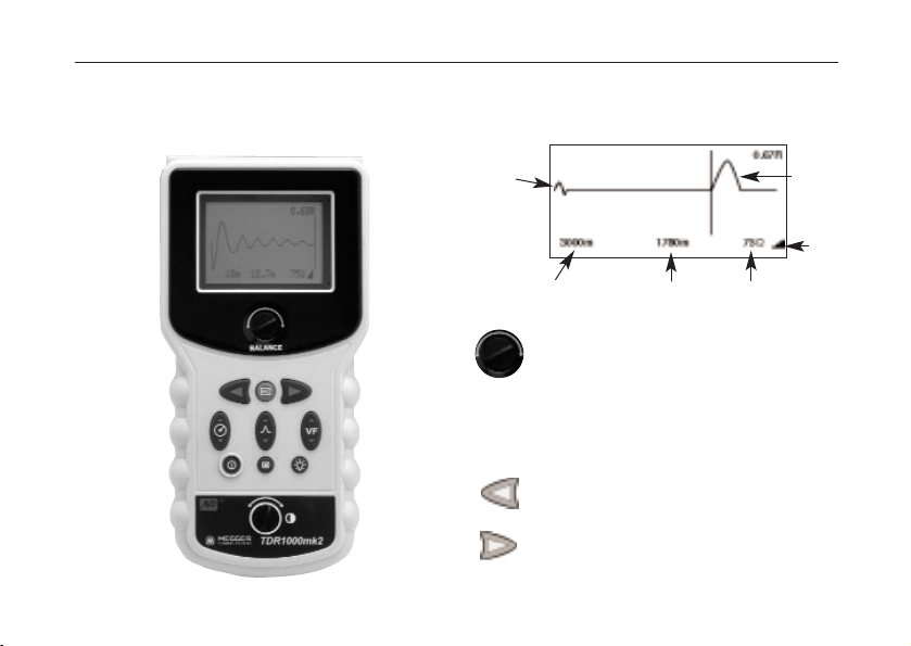
Instrument Display:
The display shows the user the current settings of the
instrument and the reflected energy trace from the
cable connected.
Tx Null: This rotary control allows the user
to match the internal balance circuit of the
CLF510F to that of the cable under test. When
correctly adjusted the majority of the displayed
transmitted pulse can be nulled out, allowing
cable features close to the start of the cable to
be identified. Refer to section TX Null for
further details.
Cursor Left: Moves the ‘distance’ cursor to
the left. Auto repeats if held down.
Cursor Right: Moves the ‘distance’ cursor to
the right. Auto repeats if held down
Transmission
pulse
Range
Distance to cursor
Impedance
Gain
Reflection
Page 8

Find key: Automatically moves the cursor to
the first potential fault (change of impedance).
Power: Pressing this button will turn the
instrument on or off depending on its current
state.
Range: A bi-directional button allowing range
adjustment from 10m (30ft) to 3km (10 000ft)
in 6 steps. The bi-directional feature allows
ranges to be selected forward and backward,
without having to scroll through all the ranges
in one direction
Gain: This control is used to increase or
decrease the gain of the instrument. This helps
the user identify faults over the entire cable
length.
Velocity Factor: Adjusts the Velocity Factor
(VF) of the instrument to match that of the
cable under test.
IMPORTANT: The VF value must match the VF of
the cable under test to give an accurate distance
measurement.
Menu: Allows the user to change the units of
measurement for Distance, Velocity Factor,
Impedance and Test Rate. Refer to menu
section later in this text.
Backlight: Pressing this button will toggle the
backlight on and off. The backlight will
automatically switch off after 1 minute
Contrast: Allows the user to manually correct
the display contrast to suit local ambient
lighting conditions.
Output Sockets: 4mm shrouded sockets designed to
accept the leads supplied with the instrument.
Battery cover: Located on the back of the
instrument and provides the user with access to the
battery compartment. The cover must not be removed
while the instrument is switched on or connected to a
cable. The instrument must not be operated with the
cover open.
USER CONTROLS AND DISPLAY
8
Page 9

9
OPERATION
General Testing procedure
Ensure the correct test leads are firmly fitted into the
sockets of the instrument.
Switch on the instrument. The CFL510F will display
the start screen for a couple of seconds, followed by
a trace. The instrument will be set to the range and
velocity factor last used. If these settings are different
for the cable under test (C.U.T) then use the
RANGE
and VF keys to set the correct values. Refer also to
‘Velocity factor’ later in this text.
Connection to Cable Under Test
Connect the test lead to the cable under test.
Connection may be made to a live system with a
voltage to earth (ground) less than 300V with an
installation (over voltage) category of III or lower.
This means that the instrument may be connected to
any fixed wiring of a building installation, but not to
primary supply circuits such as overhead cables.
A Fused Lead Set must be used to connect to
energised live systems. Refer to the accessories
section for options.
When selecting 25 cable impedance, an internal
50Hz/60Hz filter is automatically switched in.
Measuring distance to fault
Ensure that the whole length of the cable can be
seen on the display, and that the range selected is
correct.
Find key
The Find key searches for the furthest major
change of impedance. This may be a fault or the end
of the cable if this is a short or open circuit.
When found the event is displayed and the cursor
placed on the leading edge. The gain, zoom and
cursor position may need to be adjusted for accurate
measurement. Note that Find does not adjust the
TxNull or Velocity Factor.
To enable ‘difficult to see’ faults to be identified, the
gain of the instrument can be adjusted. With the gain
at minimum small changes of cable impedance may
be overlooked. By increasing the gain the fault
becomes more obvious.
If no faults are obvious, adjust the gain until any
major reflections appear. Open and short circuits
should easily be identified. Partial faults can be less
obvious.
If no significant reflections can be seen use the “TX
Null” to minimise the effect of the output pulse on
any potential “near end” faults (refer to section on TX
Null).
Page 10

In the event of no reflections being visible, increase
gain until any reflection can be easily identified.
(If no reflections can be seen, try shorting or earthing
the far end of the cable to ensure that you are
“seeing” the whole length of the cable).
The cursor can also be moved using the LEFT and
RIGHT cursor keys. Move the cursor to the beginning
of the reflection. The distance to the fault can then be
directly read from the display.
NOTE: The distance calculation is performed using
the velocity factor set in the CFL510F. If this velocity
factor is not correct for the circuit under test, the
displayed distance will be incorrect.
Opposite are shown two typical trace displays. The
top shows an open circuit at 2000m away; the second
a short circuit at 2000m away.
OPERATION
10
Page 11

Instrument Features
Menu
The Menu key allows the user to change the units of
measurement for Distance, Velocity factor, Impedance
and Test Rate.
By pressing the
Menu key the CFL510F will display:
To select a function use the GAIN key to scroll up or
down the menu.
To change the units us the LEFT or RIGHT cursor
keys.
OPERATION
11
Available options Description Options
Distance Unit The Units in which the distance to m (metres) or ft(feet).
fault is displayed.
VF Format CFL510F velocity factor RATIO, m/us or ft/us
(which should be adjusted to match
the cable under test)
Impedance Output impedance of the CFL510F 25/50 75/100
Test Rate Refresh rate 1/second or 3/second
Distance Unit m
VF Format RATIO
Impedance 75Ω
Test rate 1s
Page 12

TX Null
Without the “TX Null” control, the transmitted pulse
would be visible at the beginning of the trace,
swamping any reflections within the pulse length (the
dead zone). The ‘TX Null’ circuit matches the
characteristic impedance of the cable under test to
produce an equivalent pulse. Subtracting this
equivalent pulse from the transmitted pulse effectively
removes the dead zone from the display and allows
“near end” reflections to be seen.
NOTE: In some cases, it may not be possible to
completely null the transmitted pulse.
Velocity Factor
The velocity factor is used by the instrument to
convert the measured time for a pulse to be reflected,
into a distance. It can be displayed as a ratio of the
speed of light (eg 0.660 = 66% of the speed of light),
or as a distance per microsecond in ft/us or m/us.
If the exact length of cable is known and the
reflection from the cable end is visible then an
accurate velocity factor can be determined:
■ Locate the reflection caused by the end of the
known length of cable with the instrument set on
the shortest possible range to see the end of the
cable.
■ Locate the start of this reflection as described in
the Operation section of this manual.
■ Adjust the velocity factor until the correct cable
length is shown.
■ Note the VF value for future reference.
The measurement of the distance to the fault can
now be made with more confidence. The ability of
the instrument to accurately measure the distance to a
cable feature relies on the velocity factor being
correct. Any errors in the velocity factor are directly
related to distance measurement errors.
OPERATION
12
Page 13

OPERATION
13
Pulse Widths
As the RANGE and IMPEDANCE matching of the
CFL510F are adjusted so the duration of the
transmitted pulse changes. The pulse widths range
from 7ns to 3µs to overcome signal attenuation and
enable the instrument to see further down a length of
cable. The greater the range selected on the CFL510F,
the wider the transmitted pulse.
The accuracy of the “Distance to fault” is not affected
by the length of the pulse. However, if two or more
features exist close together (excluding open or short
circuits), then the second or subsequent feature may
be partially masked by the reflection from the first
fault. Hence, for potential multiple features, the
instrument should be used with the shortest suitable
range, and so the smallest pulse width, that can see
both features.
For output pulse characteristics, refer to output pulse
data in the CFL510F Specification at the end of this
guide.
Techniques
To improve on the accuracy of the measurement,
numerous techniques can be used, depending on the
situation encountered. Not every situation can be
described, but the following points are effective and
the most common and easily implemented methods.
Test the cable from both ends
When fault finding a cable it is good practice to take
measurements from both ends. Particularly in the case
of open circuit faults, when the true end of the cable
is not visible. If the measurement is made from both
ends, then the combined answer should equal the
expected length of the cable. Even when the true end
of the cable is visible on the display, the reflections
after the fault may be too obscure to analyse clearly.
In this case, measurement from both ends yields a
clearer picture as well as improved accuracy.
It is also good practice to follow the cable route with
a cable tracer, as not all cable runs will be straight. It
can save a great deal of time if the exact route of the
cable is known as faults are often found at these
points and can be accredited to third party
intervention.
Care and Maintenance
Other than replacing the batteries, the instrument has
no user serviceable parts. In case of failure it should
be returned to your supplier or an approved
Megger Limited repair agent.
Cleaning the instrument should only be done by
wiping with a clean cloth dampened with soapy
water or Isopropyl Alcohol (IPA).
Page 14

Except where otherwise stated, this specification
applies at an ambient temperature of 20C.
General
Ranges: 10m, 30m, 100m, 300m, 1000m, 3000m
(30ft, 100ft, 300ft, 1000ft, 3000ft, 10000ft)
Accuracy: 1% of range pixel at 0.67VF
[
Note- The measurement accuracy is for the indicated
cursor position only and is conditional on the velocity
factor being correct.]
Resolution: 1% of range.
Input Protection: This instrument complies with
IEC61010-1 for connection to
live systems up to 300V CAT
III. Fused leads must be used
if the voltage between the
terminals exceeds 300V.
Output pulse: 5 volts peak to peak into
open circuit. Pulse widths determined by range and
cable impedance:
25Ω 50Ω 75Ω 100Ω
10m
7ns 7ns 7ns 7ns
30m 20ns 20ns 20ns 20ns
100m 100ns 60ns 100ns 100ns
300m 300ns 120ns 170ns 300ns
1000m 1000ns 520ns 680ns 1000ns
3000m 3000ns 2020ns 2340ns 3000ns
Gain: Set for each range with four
user selectable steps.
Velocity Factor: Variable from 0.01 to 0.99
in steps of 0.01
Impedance matching: 25, 50, 75, 100
Tx Null: 0 to 120
Refresh Rate: Selectable from the menu.
Once per second or three
times a second.
Power Down: Automatic after 5 minutes with
no key press.
OPERATION
14
Page 15

SPECIFICATIONS
15
Backlight: Stays on for 1 minute when activated.
Batteries: Six LR6 (AA) type batteries, Manganese-
alkali or nickel-cadmium or nickel-metalhydride cells
Nominal voltage:
9V for Alkali or 7.2V for NiCad.
Battery consumption:
100mA nominal, 140mA with backlight.
(20/30 hours continuous use depending
on backlight use)
Safety: This instrument complies with IEC61010-1
for connection to live systems up to 300V
CAT III. Fused leads must be used if the
voltage between the terminals exceeds
300V.
EMC: Complies with Electromagnetic
Compatibility Specifications
(Light industrial) BS EN 61326-1, with a
minimum performance of ‘B’ for all
immunity tests.
Mechanical
The instrument is designed for use
indoors or outdoors and is rated to IP54.
Case Dimensions: 230 mm long (9 inches)
115 mm wide (4.5 inches)
48 mm deep (2 inches)
Instrument weight: 0.6kg (1.32lbs)
Case material: ABS
Connectors: Two 4mm-safety terminals.
Test Lead: 2 metres long consisting of
2 x 4mm shrouded connector
to miniature crocodile clips
Display: 128 64 pixel Graphics LCD.
Environmental: Operational Temperature:
-15C to +50C (5F to 122F)
Storage Temperature:
-20C to 70C (-4F to158F)
Page 16

ORDERING INFORMATION
16
CFL510F
Included Accessories
Test & Carry case with strap 6420-125
Miniature Clip Test Lead Set 6231-652
User Guide 6172-659
Optional Accessories
Fused prod and clip set 6111-218
For use on energised systems rated up to 300V CATIII use the fused prod and clip set Megger
Part Number 6111-218, must be used.
Page 17

17
Page 18

18
Page 19

Page 20

M
Megger Limited
Archcliffe Road, Dover
Kent CT17 9EN England
T (0) 1 304 502101
F (0) 1 304 207342
Megger
4271 Bronze Way, Dallas, Texas
75237-1088 USA
T 1 800 723 2861
T 1 214 333 3201
F 1 214 331 7399
Megger
Z.A. Du Buisson de la Couldre
23 rue Eugène Henaff
78190 TRAPPES France
T +33 (1) 30.16.08.90
F +33 (1) 34.61.23.77
OTHER TECHNICAL SALES OFFICES
Toronto CANADA, Sydney AUSTRALIA, Madrid SPAIN, Mumbai India and the Kingdom of BAHRAIN.
Megger products are distributed in 146 countries worldwide.
This instrument is manufactured in the United Kingdom.
The company reserves the right to change the specification or design without prior notice.
Megger is a registered trademark
Part No. 6172-660 V03 Printed in England 1103
www.megger.com
 Loading...