

Page 1

This instrument is manufactured in the United Kingdom.
The company reserves the right to change the specification or design without prior notice.
MEGGER is the registered Trade Mark of AVO INTERNATIONAL LIMITED. Copyright ©, AVO INTERNATIONAL LIMITED
Part No 6172-484 Edition 3 – Printed in England – 01HH
AVO INTERNATIONAL
Archcliffe Road PO Box 9007 4271 Bronze Way MEGGER SARL
Dover Valley Forge Dallas 29 Allée de Villemomble
Kent, CT17 9EN. PA 19484-9007 TX 75237-1017 93340 Le Raincy
England. U.S.A. U.S.A. Paris, France
Tel: +44 (0) 1304 502100 Tel: +1 (610) 676-8500 Tel: +1 (800) 723-2861 (U.S.A. only) Tel: +33 (1) 43.02.37.54
Fax: +44 (0) 1304 207342 Fax: +1 (610) 676-8610 Tel: +1 (214) 330-3203 (International) Fax: +33 (1) 43.02.16.24
Page 2

MEGGER
®
User Guide
Guide de l’utilisateur
B e d i e n u n g s a n l e i t u n g
I N S U L ATION MULTIMETERS
MEGGER BMM2500
Page 3
CONTENTS
2
Symbols used on the instrument are:
Risk of Electric Shock
Refer to User Guide.
Equipment protected throughout
by Double Insulation (Class II).
Equipment complies with
current EU Directives.
Equipment must
not be connected to
installations >500V.
>500V
Safety Warnings 3
General Description 4
Continuity Testing 9
Continuity Bleeper 10
Millivolt Tests 11
Capacitance Tests 12
Milliamps Tests 12
Storing Results 13
Datalogging 16
Setup Modes 18
Specification 20
Repair and Warranty 25
Page 4
3
SAFETY WARNINGS
✱ Safety Warnings and Precautions must be read and understood before the instrument is used.
They must be observed during use.
✱ The circuit under test must be de-energized and isolated before connections are made except for
voltage measurement.
✱ Circuit connections must not be touched during a test.
✱ After insulation tests, capacitive circuits must be allowed to discharge before disconnecting the
test leads.
✱ The Live Circuit Warning and Automatic Discharge are additional safety features and should not
be regarded as a substitute for normal safe working practice.
✱ Replacement fuses must be of the correct type and rating. Failure to fit the correctly rated fuse
will result in damage to the instrument in the event of an overload.
✱ Test leads, including crocodile clips, must be in good order, clean and have no broken or
cracked insulation.
✱ Ensure that hands remain behind guards of probes/clips when testing.
✱ U.K. Safety Authorities recommend the use of fused test leads when measuring voltage on high
energy systems.
NOTE
T H E I N S T R U M E N T S M U S T O N LY B E U S E D B Y S U I TA B LY T R A I N E D A N D C O M P E T E N T P E R S O N S
. U S E R S O F T H I S E Q U I P M E N T
A N D
/O R T H E I R E M P L O Y E R S A R E R E M I N D E D T H AT HE A LT H A N D SA F E T Y LE G I S L AT I O N R E Q U I R E T H E M T O C A R R Y O U T VA L I D
R I S K A S S E S S M E N T S O F A L L E L E C T R I C A L W O R K S O A S T O I D E N T I F Y P O T E N T I A L S O U R C E S O F E L E C T R I C A L D A N G E R A N D R I S K
O F E L E C T R I C A L I N J U RY S U C H A S F R O M I N A D V E RT E N T S H O R T C I R C U I T S . W H E R E T H E A S S E S S M E N T S S H O W T H AT T H E R I S K I S
S I G N I F I C A N T T H E N T H E U S E O F F U S E D T E S T L E A D S C O N S T R U C T E D I N A C C O R D A N C E W I T H T H E HSE G U I D A N C E N O T E G S 3 8
‘ EL E C T R I C A L TE S T EQ U I P M E N T F O R U S E B Y EL E C T R I C I A N S ’ S H O U L D B E U S E D .
Page 5

GENERAL DESCRIPTION
4
The MEGGER®BMM2500 Series instruments are
battery powered Insulation and Continuity testers,
with a measurement capability from 0,01Ω
Continuity to 200GΩ Insulation.
Offering multi-voltage facilities, the instruments
take full advantage of microprocessor technology
and feature a large liquid crystal display combining
digital and analogue readings. The analogue display has the benefit of indicating trends and fluctuations in readings, while the digital readout gives
direct accurate results. The display is also backlit
giving clear visibility even in low light conditions.
The BMM2500 Series instruments have the unique
capability of being able to measure voltages down
to a resolution of 0,1mV. This gives the user the
option to fit a wide variety of transducers to further
enhance the capabilities of the BMM Series instruments, eg temperature or humidity measurement.
A customised connector on the top of the instrument enables the optional M E G G E R®S P 1
Switched probe to be used for two handed probe
operation.
The 250V, 500V and 1000V ranges can be used to
test electrical installations in compliance with
BS7671 (16th Edition IEEE Wiring Regulations)
IEC364 and HD384, since each range has a 1mA
minimum test current at the minimum pass values
of insulation specified in these documents. The
100V range (BMM2580) is ideal for testing
telecommunications equipment which would be
damaged by higher voltages. The 50V range
(BMM2580) is useful for testing sensitive equipment, such as electronic components, and computer peripherals.
The BMM2500 series instruments have a current
facility which enables up to 500mA to be measured, this together with Ω, V and mV ranges
means that the instrument can realistically be used
in situations where previously a multimeter would
be needed. For higher currents an optional current
clamp is available.
Page 6

5
The BMM2500 series instruments have an
RS232 interface built in, and will allow the storage and download of results to a PC. The instruments come with all the necessary software to
download and tabulate the results. The download format is also AVO Powersuite compatible
enabling instruments to form part of an integrated test and certification system. The BMM2500
series instruments also have the capability to
data-log results over an extended time period so
that long term measurements of systems can be
taken.
Designed to IEC1010-1 the BMM2500 Series are
p rotected against connection to a 500V
Category III supply. The instruments have a basic
accuracy of ±2% at 20°C. The instruments are
waterproof and dustproof to IP54. This helps
maintain accuracy and ensures maximum reliability in harsh environments.
Page 7
OPERATION
6
Refer to Safety Warnings before using
the instrument
Testing is automatically inhibited if:
• An external voltage >25V is present when
switched to any insulation range position.
• An external voltage >10V is present on all
other ranges (excluding OFF/V/mV).
The external voltage is indicated on the display,
on insulation ranges an audible bleeper will
sound if a test is attempted.
Live Circuit Warning
When more than 25V is applied to the terminals
in the insulation ranges, the instrument defaults
to a voltmeter and gives an audible warning if a
test is attempted. On all other switch positions
except O F F / V / m V when more than 10V is
applied the default voltmeter will be activated.
Testing will be inhibited.
Voltage Testing on High Energy Systems
Use extreme care when using or measuring volt-
ages above 30V, particularly in high energy systems. Fused test leads are available as optional
accessories for local situations where increased
protection is required.
Auto-shut Off
To conserve battery life, Auto-shut Off (pre c e d e d
by a series of bleeps) operates after appro x .
1 0 minutes of instrument inactivity on insulation,
5 minutes on all other ranges. If the instrument is
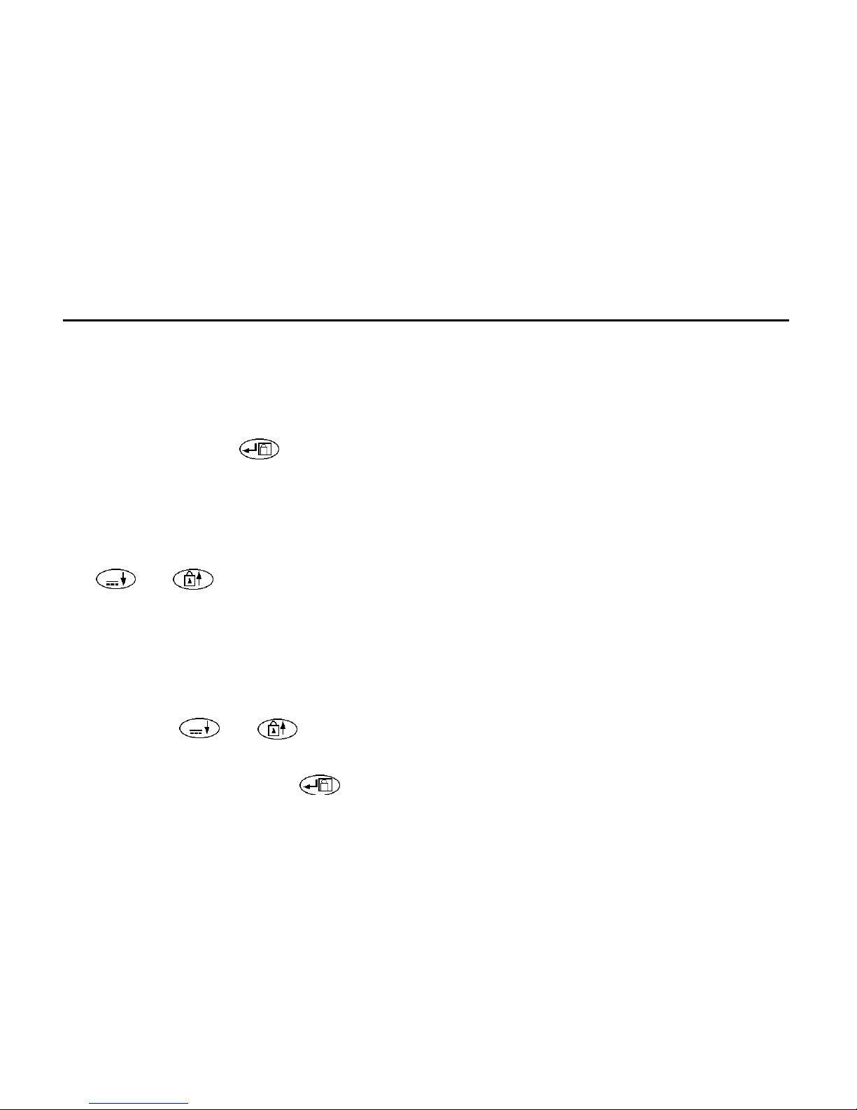
switched on while holding the k e y, the Auto
s h u t - O f f time is extended to 60 minutes. To
re s t o r e operation after Auto-shut Off, select O F F
followed by the re q u i red switch position.
Note: It is recommended that the instrument is
switched to the OFF position when not in use.
Backlight
The backlight is activated by pressing the
key. The backlight will remain illuminated
for approx. one minute before automatically
switching off to conserve battery life, alternatively the key can be re-pressed.
∼
Page 8

7
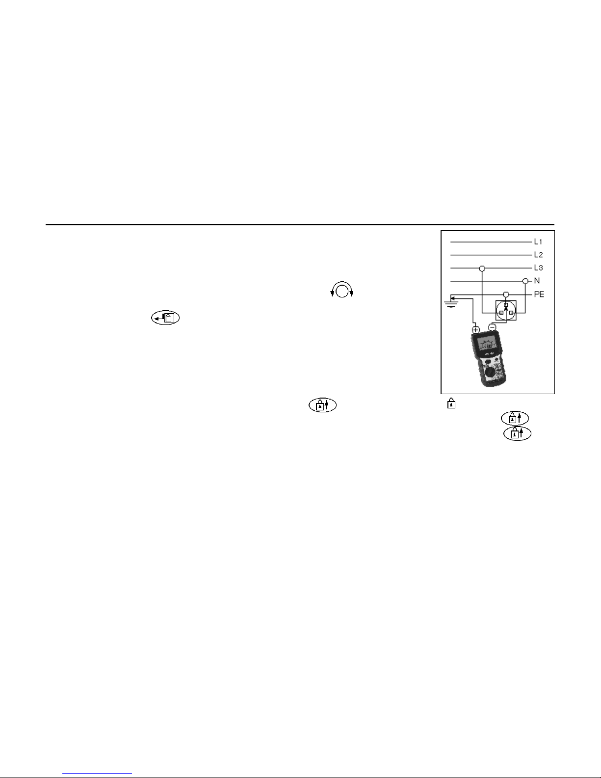
Insulation
Tests (MΩ)
(See fig.1)
The insulation tests
apply a known voltage to the circ u i t
under test and
m e a s u re the re s u l ting leakage curre n t .
The circuit under
test must be completely d e - e n e r-
g i s e d and i s o l a t e d
b e f o re test connections are made.
Insulation tests are only initiated when the TEST but-
ton is pressed.
1. Set the range switch to the test voltage
required.
2. Connect the test leads, first to the instrument,
and then to the isolated item under test.
3. Press the TEST button to activate the test
voltage. Take the reading.
4. Release the TEST button at the end of the test.
( P ress the TEST button if the l t b f e a t u re is
enabled). The last reading will hold on the display.
5. Any capacitive circuits charged during a test
will automatically discharge. If significant
voltage remains the voltage warning will occur
and the voltage present displayed.
6. Remove the test leads only when no voltage is
indicated.
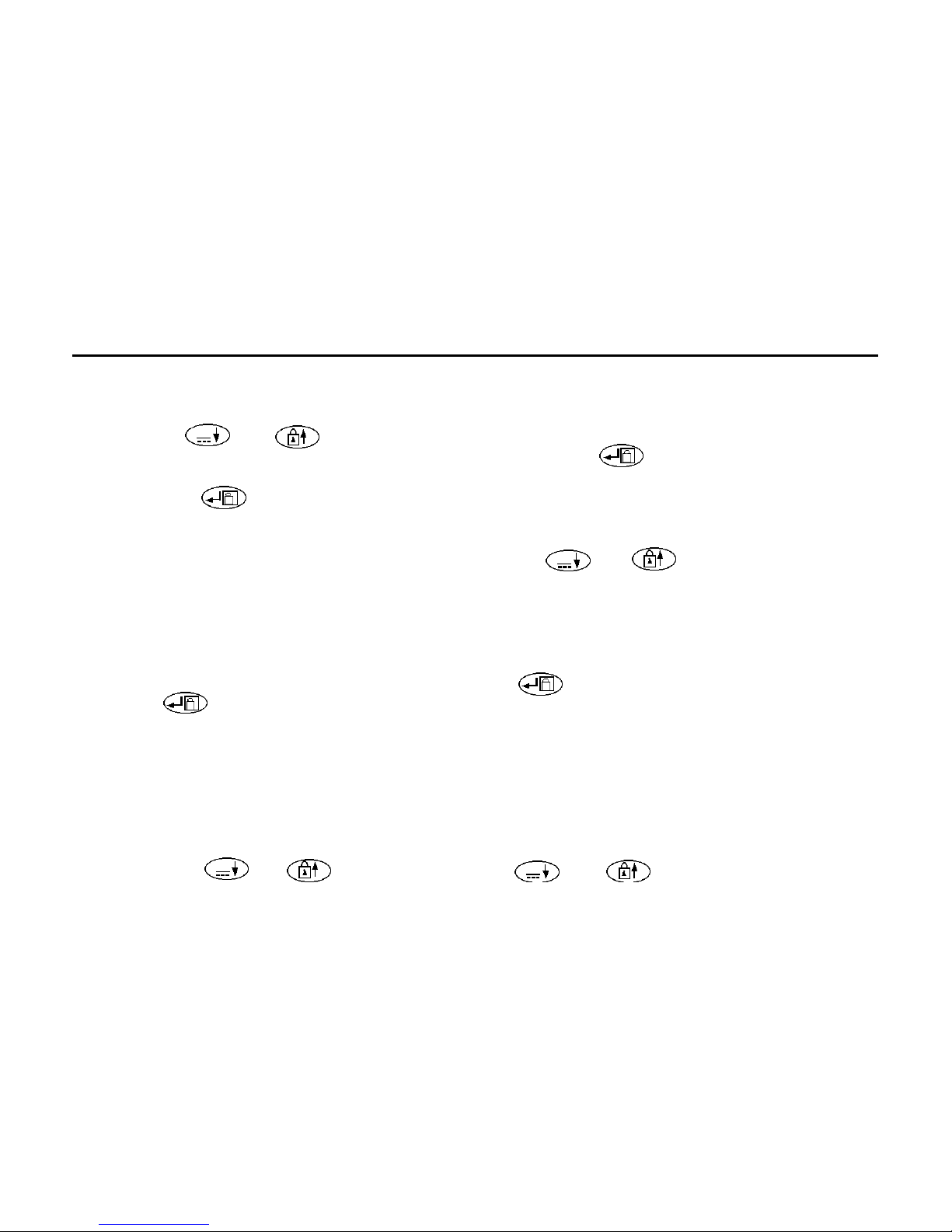
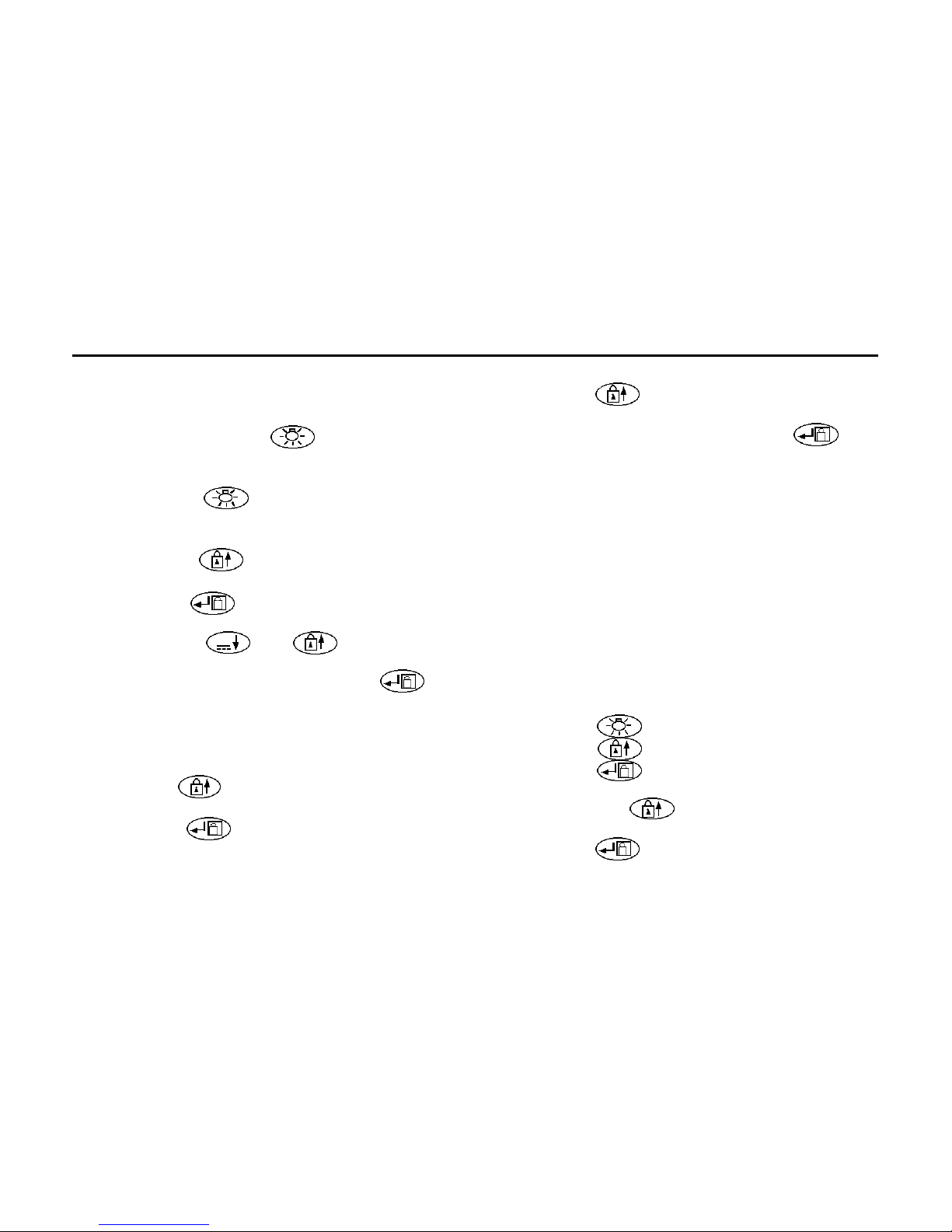
Locking Test Button (ltb)
When it is desired to do a long insulation test, the
test can be ‘locked on’ by pressing the XXXXX key
while the test button is held down. The warning
will appear on the display and both buttons may be
released whilst the test continues. The next press
of the test button will terminate the test.
Note: There is a short delay on the first operation
of ‘1000 V’ range, each time the range is selected.
This is to prevent accidental application of 1kV.
The MΩ range features a leakage current display.
Leakage current is the value of current that flows
during the insulation test. To view the leakage current press the XXXXX key. To view insulation resistance press the XXXXX key again.
FIG.1
∼
Page 9
8
Good procedure whilst Insulation Testing
Care must be taken when taking measurements
greater than a few GΩ. The leads must be clean
dry and in good condition. They must also not be
allowed to tangle. It is also advisable that the
switched probe SP1 is not used as the accuracy at
high value measurements is not guaranteed. The
instrument should also be clean and dry with particular attention paid to the terminals. Also attempt
to reduce any leakage that may give erroneous
results on the item under test.
Polarisation Index Testing
Polarization Index (P I) is the term applied to the
Dielectric Absorption Ratio when resistance values
a r e measured after 1 minute and again after 10 min-
utes. Polarization Index is then the resistance value
after 10 minutes divided by the resistance value
after 1 minute. The test can be run at any voltage.
M o re detailed information on P I Testing and value
assessment can be found in AVO International publications listed in the Accessories page.
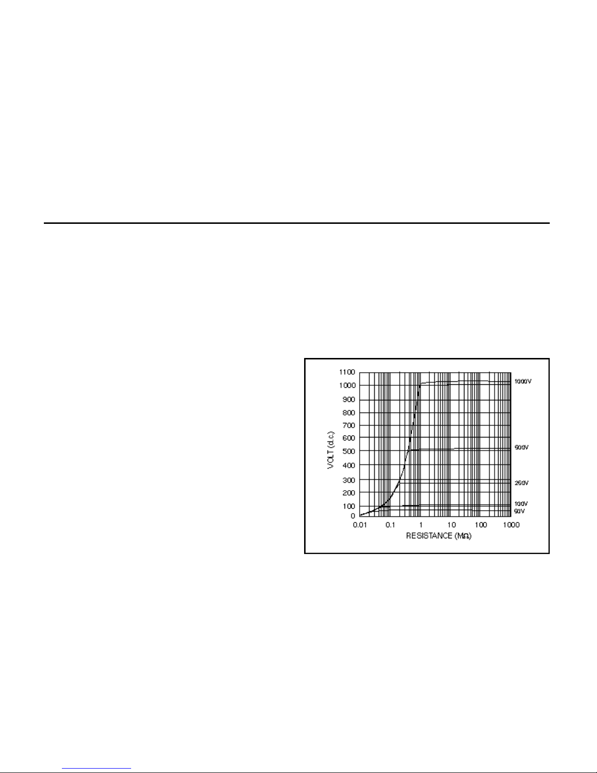
Automatic Discharge
When the TEST button is released after an insulation test (or re-pressed if ltb feature is enabled), a
200kΩ load is automatically switched across the
terminals to discharge the item under test. Any
voltage present will be indicated on the display so
that the discharge can be monitored.
Typical Terminal Voltage Characteristics
Page 10
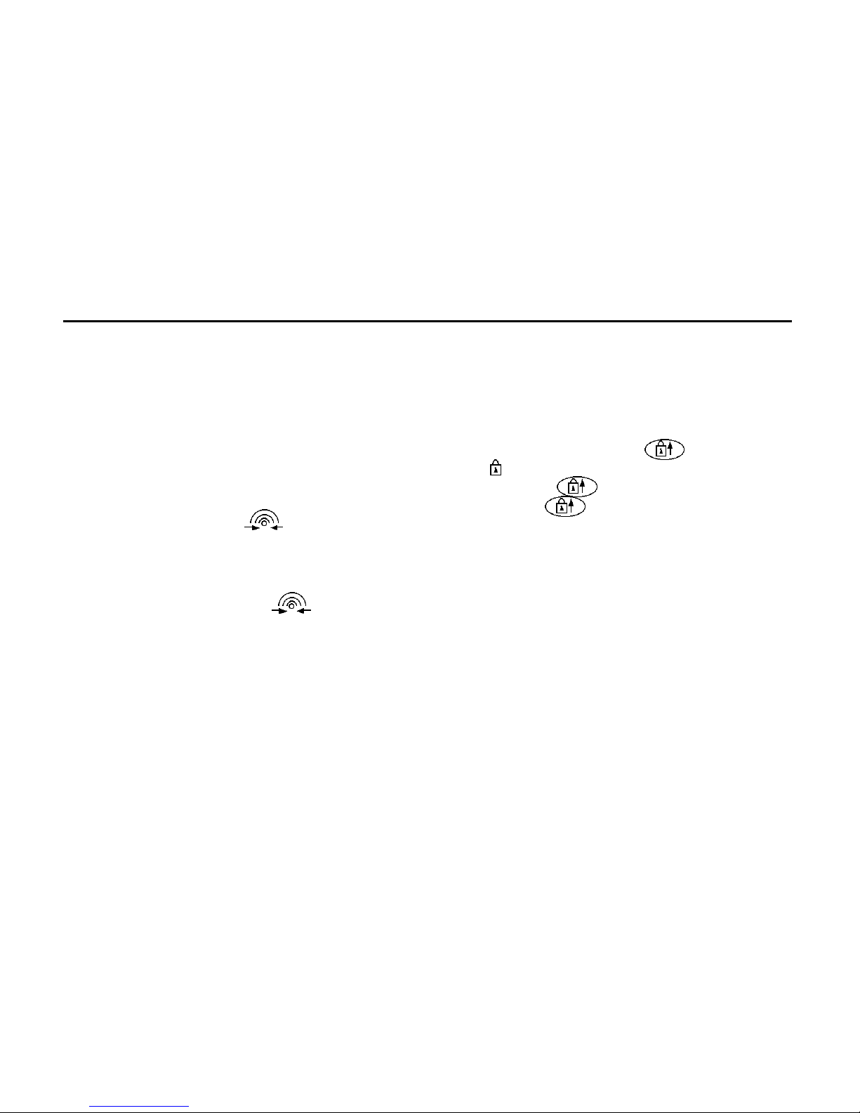
Continuity Testing (Ω) (See fig.2)
The continuity tests are activated when the probes
make contact of less than a few kΩ. The test operates without the need to press the TEST button.
When the test leads are removed the reading will
hold for a few seconds and then reset. To recall the
last result press the XXXXX key. This range is not
suitable for diode testing since the automatic contact detector will not be activated when connected
to a diode.
1. Set the selector switch to Ω.
2. Connect the test leads.
3. The test will activate automatically.
4. After the test probes are disconnected, the
reading will be held for a few seconds.
Zeroing of Test Lead Resistance
The resistance of the test leads can be nulled on the
continuity range (up to 9,99Ω). The null information
is retained in non-volatile memory and so will be
re m e m b e red when the instrument is switched off .
1. Select the Continuity range.
2. Short the test leads across a known good
conductor using prods.
3. When the reading has
stabilised, press the
TEST button. The
z e ro offset symbol
will appear.
4. To release the zero
offset press the test
button again.
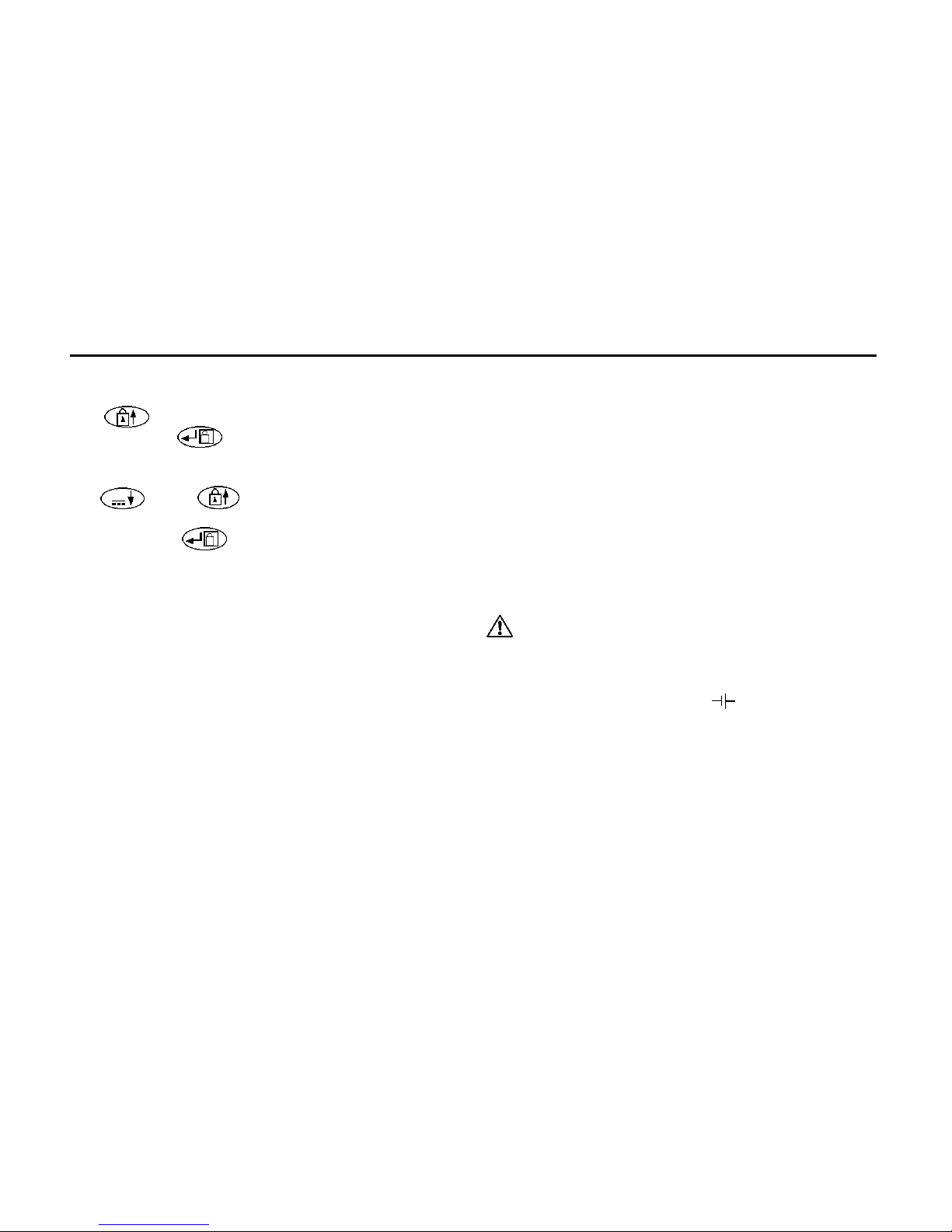
The continuity range
f e a t u res a range lock
f a c i l i t y. To LOCK the
continuity range press the
key, the LOCK symbol will appear. To scroll
through the available ranges press the key.
To de-select the LOCK feature hold the key
down.
9
FIG.2
Page 11
10
Possible sources of error
Measurements and results can be effected by the
following:
• The impedance of operating circuits connected in parallel
• Impedance such as inductors that vary during
the measurement
• A poor connection to the circuit under test.
Continuity Bleeper
The continuity bleeper sounds continuously when
less than 5 Ω is detected. Short bleeps will sound
for resistances lower than a few kΩ and above 5Ω.
1. Set the selector switch to
2. Connect the test leads.
Display: Audible:
<5Ω continuous bleep
<3kΩ short bleep
>3kΩ no bleep
Resistance Tests (kΩ)
This is a low voltage (5 V) low current (25 µA) test
for sensitive electronic equipment. It operates in
the same way as the continuity ranges.
1. Set the selector switch to kΩ.
2. Connect the test leads.
3. The test will activate automatically.
The kΩ range features a range lock facility. To
LOCK the kΩ range press the key, the LOCK
symbol will appear. To scroll through the available
ranges press the key. To de-select the L O C K
f e a t u re hold the key down.
The resistance range is protected by a high impedance method and therefore if the instrument is
connected to a live circuit the fuse will not blow as
on the insulation, continuity and buzzer ranges.
The instrument will merely indicate the applied
over-voltage.
Diode Testing
This range can also be used for diode testing, the
positive terminal being the source of the test current. A forward biased semi-conductor junction will
typically measure 15 to 30kΩ, and a reverse junction much higher. These features together with the
small test current and wide measurement range
Page 12
∼
11
(0,01kΩ to 10000kΩ) make the resistance range
very useful for general purpose testing.
Voltage Tests (V)
If >1V a.c. or d.c. is present at the terminals the
measured voltage is indicated on the display. The
voltage display will function within specification
even if the fuse has blown.
If the voltmeter operation is in question, test the
voltmeter on a known source.
1. Set the selector switch to V.
2. Connect the test leads.
3. After a short settling time, the reading will be
displayed automatically.
To view the frequency of the a.c. V being measure d
p ress the k e y. The frequency will be displayed
in the range 16Hz-460Hz. To view a.c. V press the
key again.
Millivolt Tests(mV)
The measured a.c. or d.c. voltage is indicated on
the display.
1. Set the selector switch to mV.
2. Select either a.c. or d.c. mV using the
key.
3. Connect the test leads.
4. After a short settling time, the reading will be
displayed automatically.
Note: Live circuit warning does not function on mV
range.
Zeroing of d.c. mV (no a.c. mV zero facility)
To zero the d.c. mV range, short the leads together in the d.c. mV position, wait for the reading to
settle and then press the TEST button. Up to
9,9mV can be zeroed on the d.c. mV range. The
symbol will appear to indicate the zero has
been adjusted.
1. Select the d.c. mV range.
2. Short the test leads together.
3. When the reading has stabilised, press the
TEST button. The zero offset symbol will
appear.
4. To release the zero offset press the TEST but-
ton again.
To view the frequency of the a.c. mV being measured press the key. The frequency will be
displayed in the range 16Hz-460Hz. To view a.c.
Page 13

12
mV press the key again. For inputs less than
10mV frequency is not displayed.
Capacitance Tests (uF)
(BMM2580 only)
The measured capacitance is indicated on the display.
1. Set the selector switch to uF.
2. Connect the test leads to the circuit under test.
3. After a short settling time, the reading will be
displayed automatically.
Zeroing of uF
To zero the uF range, disconnect the leads, wait for
the reading to settle and then press the TEST but-
ton. Up to 10,0nF can be zeroed on the uF range.
The symbol will appear to indicate the zero
has been adjusted.
1. Select the uF range.
2. Disconnect the test leads from the circ u i t
under test.
3. When the reading has stabilised, press the
TEST button. The zero offset symbol will appear.
4. To release the zero offset press the test button
again.
The range is suitable for the testing of discrete
components and short low interference level signal
lines. If electrolytic capacitors are being tested
then the red lead should be connected to +ve of
the capacitor. This range is not suitable for checking capacitance of signal lines which are subject to
high levels of a.c. interference.
When the test is started – – – will show on the display, if there is excessive noise this symbol will
remain or flash indicating that there is too much
noise for a result to be reached.
Milliamps Tests (mA)
Because of the low source impedance associated
with current measuring this test has an added feature ensuring that when the range is first entered
the default voltmeter is visible. Testing will be inhibited if more than 25V is present at the terminals. To
start testing the TEST button should be pressed
and held down for approx. 2 seconds to activate
the mA range. Once activated, the TEST button
no longer needs to be used and the measured
value will be displayed automatically. To switch the
display between a.c. and d.c. press the
Page 14
∼
13
key.
1. Set the selector switch to mA.
2. Connect the test leads.
3. Select either a.c. or d.c. m A using the
k e y.
4. Press and hold down the TEST button for
approx. 2 seconds.
5. After a short settle time, the reading will be
displayed automatically.
To view the frequency of the a.c. mA being mea-
sured press the key. The frequency will be
displayed in the range 16Hz-460Hz. To view a.c.
mA press the key again. For inputs less than
10mA frequency is not displayed.
Storing Results on MΩ and Ω (RCL)
After an insulation test or continuity test the result
is displayed on the screen, this may be saved with
additional information. A circuit number (1-99) may
be assigned and circuits may be grouped using the
distribution board feature. In this way, when downloading to AVO PowerSuite, the results can be easily split into different test schedules. When the
results are displayed or printed, a change in the
distribution board is indicated.
Changing Distribution Boards (DB)
Before a test the distribution board number may be
changed as follows:-
1. Move the rotary selector switch to the RCL
position. The code rcl is displayed.
2. Press the key. The currently selected DB
code is displayed, e.g. d01.
3 . This number may be changed using the
and keys to display the re q u i red number.
4. The number can be accepted by pressing the
key, or aborted by pressing the EXIT button.
5. When the number is saved the code Std is
displayed (accompanied by a long bleep) to
confirm that the data has been saved.
∼
∼
Page 15
14
Testing may now continue with all subsequent
results associated with the new distribution board
number.
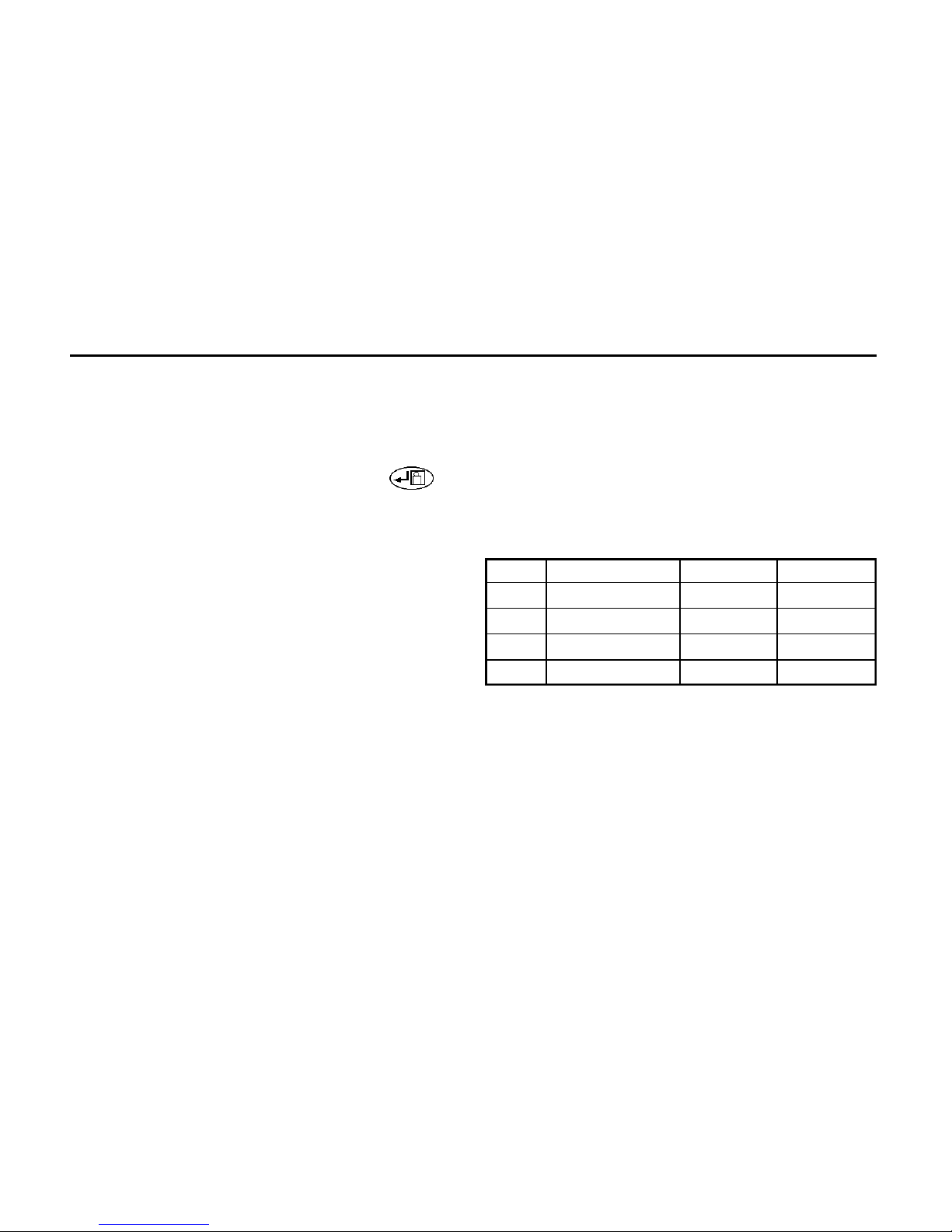
Storing a result
On completion and display of the measurement:-
1. Press and hold the key. After about 1
second, a bleep will be heard. For both
Continuity and Insulation, a code, as given in
the following table is displayed. This code is
used to describe the circuit tested and can
accordingly be modified by the user.
2. The code may be changed by pressing the
and keys.
3. The code may be accepted by pressing the
key, or aborted by pressing the EXIT button.
4. The circuit number is then displayed as
2 digits e.g. c01.
Note:- Many different tests may be saved under
the same circuit number.
5. The circuit number may be changed by
pressing the and keys to display
an appropriate number.
6. The number can be accepted and the
results saved by pressing the key, or the
procedure aborted by pressing the EXIT button.
7. When the result is saved, the code Std is
displayed (accompanied by a long bleep) to
confirm that the data has been saved. The
display of FULL indicates that there is no more
test storage. Approx. 300 results can be stored
in memory.
Test to be Saved Display code Meaning
Continuity r1 Single CCT
r2 Single CCT
rr1 Ring CCT
rr2 Ring CCT
rrn Ring CCT
r12 R1+R2 ReturnCCT
Insulation n_e N-PE
L_n L-N
L_E L-PE
L_L L-L
∼
∼
Page 16
15
Delete all data
1. Move the rotary selector switch to the RCL
position. The code rcl is displayed.
2. Press the and keys together. The
code dEL is displayed.
3. Confirm that the data is no longer required by
pressing the key or abort by pressing any
other key. The code rcl is displayed.
Print Results (see Setup Modes)
1. Connect printer and the instrument with a ser-
ial printer lead.
2. Move the rotary selector switch to the RCL
position. The code rcl is displayed.
3. Commence the printout by pressing the TEST
button. Abort at any time by pressing and holding the k e y . The code rc l is displayed.
Retrieve Stored Results
It is possible to view previously stored test results
by switching the rotary switch to the RCL position.
1. Move the rotary selector switch to the RCL
position. The code rcl is displayed.
2. Select the re q u i red distribution board by
pressing the and keys.
The distribution board numbers are shown in
the order that the results were stored. A long
bleep is sounded when the end of the list is
reached.
3. Press the key to list the circuit numbers
used in the currently displayed distribution
board or press the EXIT button to return to the
RCL display.
4. Select the required circuit number by pressing
the and keys. The circuit numbers
are shown in the order that the results were
stored. A long bleep is sounded when the end
of the list is reached.
5. Press the EXIT button to return to the distribution board selection screen, or press the
XXXXXkey to show the stored test codes. The
following codes are used to identify test
results:-
Code Meaning
Con Continuity Test
InS Insulation Test
6. Select the re q u i red test by pressing the
and keys. The tests are shown in
∼
∼
∼
∼
Page 17
16
the above order. Hold a key down to autorepeat. A long bleep is sounded when the end
of the list is reached.
7. Press the EXIT button to return to the circuit
number selection screen, or press the key
to scroll through the stored test results,
together with any additional connection
information.
Download to PC
The BMM series has been designed to be used
with AVO Powersuite for Windows which will
accept the test results and enable the production
of various certificates, including Periodic
Inspection and Completion. The CD supplied with
the instrument contains AVO Download Manager
Program. This enables stored and data-logged
results to be downloaded to a PC, the creation of
simple test report files which may be exported to
other applications and used to create data backups or reports/certificates. Download manager
also enables certain changes to be made to your
instrument setup such as changing the 2nd lan-
guage of the printouts. The CD contains a user
guide giving you full instructions on the use of
Download Manager.
Cable Configuration
Normally, a double-ended 9-way ‘D’ female socket
lead suitable for connecting PC to PC is required.
This lead should not exceed 3m in length. A lead is
available as an accessory, or one can be made up
as follows:–
Datalogging
Datalogging means the automatic recording of
measurements at regular intervals over an extended period, for viewing at a later time. Results are
held in the internal memory of the tester, but can
only be extracted by means of a PC connected via
the RS232 port.
Signal Insulation Tester 9-way ‘D’ 25-way ‘D’
Rx 2 3 2
Tx 3 2 3
DSR 6 4 20
GND 5 5 7
Page 18
17
Storage v. Datalogging Comparison.
By storage, we mean the saving to memory of
results one-by-one as tests are performed. Each
result has to be individually saved after associating
it with user-selectable connection data and circuit
number, along with a previously chosen distribution board number. However, when data logging is
running, results are automatically and continuously saved to memory and no other information is
recorded.
Storage and logging are mutually exclusive functions. The instrument cannot be set up to perform
both operations at any given time. If a result is
stored, then all logged data is erased, and vice
versa. Also, only one set of logged data can be
held in memory. A new logging session will erase
the previous data. This differs in behaviour from the
storage function, in which data from successive
tests accumulates in the memory until it is full.
Another difference between storage and logging is
that the former applies only to insulation and continuity testing, whereas all types of measurement
can be logged (buzzer range excluded).
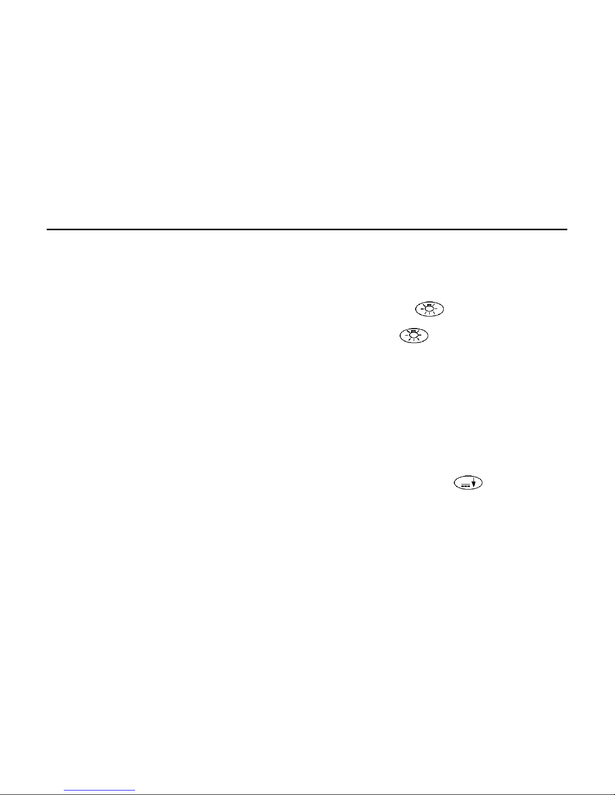
Starting a logging session
Once logging has been enabled and the interval
set up, a session of data-logging can begin. (see
Setup Modes)
1. Hold down the key and turn the rotary
switch to the desired function.
2. Release the key. The message log will
be seen. To confirm that logging is required,
p ress the display key and a confirming
message will be shown briefly.
3. Pressing EXIT will cancel logging and off will
be displayed.
If data-logging is turned on, it will commence as
soon as the test starts. That is, immediately on
volts, millivolts, ohms, kΩ and capacitance functions, or when the test button is pressed on insulation and milliamps ranges. On milliamps or millivolts functions, press theXXXXXkey if required,
after logging has started.
Stopping a logging session
While a logging session is running, it can be
stopped at any time by turning the range switch.
Any data logged up to that point will be retained.
∼
Page 19

18
Alternatively, logging can be left running and will
stop automatically a short while after the memory
becomes full.
The number of results which can be logged is
about 300, after which the message ‘full’ will be
flashed on the display for a few minutes. The
instrument will then shut down.
Other considerations
Note that the batteries may not last through the
whole logging session, depending on their condition and on the log interval which has been set. If
the batteries should fail, any results already logged
will be retained. Note also, that if the TEST button
has been set for non-latching operation, this will be
temporarily overridden during logging of insulation
results, giving a press-to-start, pre s s - t o - s t o p
action. The TEST button’s mode of operation will
return to its original setting after the logging session has finished.
Viewing logged data.
Logged results can only be retrieved via the instrument’s RS232 port, using a PC connected via a
serial cable. The disk supplied with the instrument
carries a programme capable of handling the data.
The method is similar to that for ‘downloading’
stored results. For further information see the section entitled “Download to PC”. Note that on millivolts d.c. and milliamps d.c. measurements, the
frequency result is always set to zero. On millivolts
a.c. and milliamps a.c. measurements, the frequency result is set to zero if the frequency could
not be measured.
Setup Modes
Serial Printer configuration
The printer should be set to 9600 baud, 8 bit data,
no parity and 1 stop bit. This instrument uses a
special isolated serial interface which is powered
from the PC or printer. In the unlikely event that
your PC or printer is not able to power the interface, it will be necessary to provide an additional
supply. Contact AVO Product Support for details.
Printer Setup Mode
The instrument cannot respond to a busy signal
Page 20
∼
19
given by a printer, and therefore waits at the end of
each line. This time (“Printer delay time”) and the
printer report language can be changed.
1. Press and hold the key then turn the
rotary selector switch from the OFF position to
the RCL position. The code Pdt is displayed.
2. Release the key.
To change the Printer speed
1. Toggle the key to scroll through and
display the code Pdt
2. Press the key. The current setting is
displayed.
3. Toggle the and keys until the
required setting is displayed.
4. To save the new setting, press the key.
The bleeper sounds and std is displayed. To
abort the new setting, press the EXIT button.
To select the printer language
1 . P ress the key to scroll through and dis-
play the code l n g.
2 . P ress the key. The current printer re p o r t
language is displayed as 1 (English) or 2 (as
given on the type label on the User Guide cover).
Note: Language 2 can be changed – see below.
3. Press the key until the required language
setting is displayed
4. To save the new setting, press the key.
The bleeper sounds and is Std displayed. To
abort the new setting, press the EXIT button.
Changing the Second Printer Language
Language 2 can be changed using AVO Download
Manager Program supplied with your instrument. Full
instructions are contained in the User Guide with the CD.
Data-logging
Enabling/disabling data-logging:
The factory setting is that logging is disabled and
storage is enabled.
1. Turn the range knob to ‘RCL’ while holding
down the key. Pdt will be displayed.
2. Press the key until log is showing
3. Press the key to show the current status
of the logging function, i.e on or off.
4. Pressing the key toggles the setting
between on and off.
5. Press the key to accept the setup, or the
EXIT button to quit.
Page 21
∼
20
Setting the data-logging interval.
1. While log is being displayed, press the
key. Int will appear on the display.
2. Press the key to see the value of the logging interval (in seconds)
3. Set the interval in 10 second steps with the
and keys (max. value 1990 sec-
onds, min. value 10 seconds)
4. Press the key to accept the new value,
or the EXIT button to quit.
5. Press the EXIT button again to escape from
the logging setup screens. The display will
s h o w rc l.
Using the MEGGER SP1 Switched Probe
Operation
The MEGGER SP1 is an accessory for designated
MEGGER installation test instruments. When fitted
in the specially designed connector, in place of the
existing ‘Low’ lead, the SP1 acts as a remote test
button to operate the instrument and as a ‘Low’
probe. This simplifies instrument control and twohanded probing. The SP1 is suitable for use with
MEGGER insulation test instruments up to 1kV
output test voltage.
Safety
Meets the safety requirements for double insulation to IEC1010-2-031 (1995), EN61010-2-031
(1995), IEC 1010-1 (1995), EN61010-1 (1995)
Category III* 300 V phase to earth and 500V phase
to phase. The probe is fitted with an internal, nonreplaceable fuse, to protect the user should the
probe be used accidentally in conjunction with a
testlead in the low terminal.
*Relates to transient overvoltage likely to be found
in fixed installation wiring.
Do not use the probe if any part of it is
damaged.
Battery Replacement
When the low battery symbol appears, the cells
are nearly exhausted and should be replaced as
soon as possible. Use Alkaline cells IEC LR6 (AA)
or NiCd rechargeable. To install or replace the
cells, disconnect the test leads, switch the instrument to OFF and loosen the captive screws on the
rear of the battery compartment. Remove the
cover and disconnect the battery holder from the
battery leads. Ensure that the replacement cells are
Page 22

21
fitted with the correct polarity in accordance with
the label in the battery holder. Reconnect the battery holder to the battery leads. Replace and resecure the battery compartment cover. Remove
the cells if the instrument is not going to be used
for an extended period of time.
Fuse Checking and Replacement
To check the instrument fuse, switch to an insulation range and press the TEST button. The symbol
XXXX will appear if the fuse is ruptured. To replace
the fuse, disconnect the test leads, switch the
instrument OFF and loosen the captive screws
holding the battery compartment cover in place.
Remove the cover and replace the fuse. Replace
and re-secure the battery compartment cover.
Page 23

Specification
22
(All quoted accuracies are at +20ºC.)
INSULATION RANGES
Nominal Test 250V,500V,1000V (BMM2500)
Voltage (d.c.): 50V,100V,250V,500V,1000V (BMM2580)
Test voltage accuracy: +15% maximum on open circ u i t
Short circuit curre n t : < 2 mA
Test Current on load: 1mA at min. pass value of insulation
specified in BS7671, HD384 and
IEC 364, 2mA max.
Accuracy:
(BMM2500)
Range Full Scale Accuracy
1000V 20GΩ ± 2% ± 2 digits ± 0,2% per GΩ
500V 10GΩ ± 2% ± 2 digits ± 0,4% per GΩ
250V 5GΩ ± 2% ± 2 digits ± 0,8% per GΩ
(BMM2580)
Range Full Scale Accuracy
1000V 200GΩ ± 2% ± 2 digits ± 0,2% per GΩ
500V 100GΩ ± 2% ± 2 digits ± 0,4% per GΩ
250V 50GΩ ± 2% ± 2 digits ± 0,8% per GΩ
100V 20GΩ ± 2% ± 2 digits ± 2,0% per GΩ
50V 10GΩ ± 2% ± 2 digits ± 4,0% per GΩ
Note: Above specifications only apply when high quality
silicone leads are being used.
Measuring Range:
0,01MΩ to 200GΩ (0-100GΩ on analogue scale).
EN61557 Operating range: 0,10MΩ to 1,00GΩ
Leakage Current: 10% ±3digits
CONTINUITY
Measuring Range: 0,01Ω to 99,9Ω (0 to 10Ω on
analogue scale)
EN61557 Operating range: 0,10Ω to 99,9Ω
Accuracy: ±2% ±2 digits
Open circuit voltage: 5V ±1V
Test current: 210mA ±10mA (0-2Ω)
Zero offset at probes: 0,10Ω typical
Lead resistance zeroing: Up to 9,99Ω
Noise rejection: 1V rms 50/60Hz
Buzzer: Operates at less than 5Ω
(approx).
RESISTANCE
Measuring Range: 0,01kΩ to 9,99MΩ (0 to
100MΩ on analogue scale)
Accuracy: ±3% ±2 digits
Open circuit voltage: 5V ±1V
Short circuit current: 25µA ±5 µA
Page 24

23
VOLTAGE
Measuring Range: ±1V to ±500V (0 to 1000V
on analogue scale)
Accuracy: 0-500V d.c. ±2% ±3 digit
0-500V a.c (50/60Hz) ±2% ±3 digits
0-500V 400Hz a.c. ±5% ±3 digits
Input resistance: approx 200kΩ.
Detector Threshold: 1V
MILLIVOLTS
Measuring Range: ±0,1mV to ±1999mV
(0 to 1000mV on analogue
scale)
Accuracy:
0,1mV to 10mV d.c. or a.c. (50/60Hz) ±2% ±5 digits
10mV to 1999mV d.c. or a.c. (50/60Hz) ±2% ±3 digits
0,1mV to 10mV a.c. (16-460Hz) ±5% ±7 digits
10mV to 1999mV a.c. (16-460 Hz) ±5% ±5 digits
d.c. milliVolts zeroing: Up to 9,9mV
Input resistance: >3MΩ
CAPACITANCE
Measuring Range: 0,1nF to 9,99uF
Accuracy: ±3% ±2 digits ±0,2nF
uF zeroing: Up to 10nF
MILLI-AMPS
Measuring Range: 0,1mA to 500mA (0 to 1000mA on
analogue scale)
Accuracy:
0,1mA to 10mA d.c. or a.c. (50/60 Hz) ±2% ±5 digits
10mA to 500mA d.c. or a.c. (50/60 Hz) ±2% ±3 digits
0,1mA to 10mA a.c. (16-460 Hz) ±5% ±7 digits
10mA to 500mA a.c. (16-460 Hz) ±5% ±5 digits
FREQUENCY
Measuring range: 16Hz to 460Hz
Accuracy: ±1% ±1digit
Page 25

24
Basic and service errors for
Insulation and Resistance ranges.
The basic error is the maximum inaccuracy of the instrument under ideal conditions, whereas the service error is
the maximum inaccuracy taking into effect of battery volt-
age, temperature, interference, and system voltage and
frequency, where applicable. After determining the service
error, we can then calculate the measurement range. This
is the range of measurement over which the error in service is less than 30% of the reading. Digital instruments
are affected by the number of digits error – for example a
value 0,10Ω measured with the continuity range may give
a display in the range 0,07Ω to 0,13Ω which is a maximum
error of 30%. Therefore the measurement range measuring low resistance is 0,10Ω to 99,9Ω. When checking that
a measurement does not exceed a limit, the service error
needs to be taken into account and these tables enable
this to be done quickly and easily. These will guarantee
that the value being measured is greater than or less than
the limit value specified as appropriate.
Insulation Resistance – MΩ
Limit Min. Indicated Reading Limit Min. Indicated Reading
0,10 0,14 2,00 2,12
0,20 0,25 3,00 3,16
0,30 0,35 4,00 4,20
0,40 0,46 5,00 5,24
0,50 0,56 10,00 10,8
0,60 0,66 20,00 21,2
0,70 0,77 30,00 31,6
0,80 0,87 40,00 42,0
0,90 0,98 50,00 52,4
1,00 1,08 100,00 94,0
Continuity Resistance – Ω
Limit Max. Indicated Reading Limit Max. Indicated Reading
0,10 0,06 2,00 1,88
0,20 0,15 3,00 2,84
0,30 0,25 4,00 3,80
0,40 0,34 5,00 4,76
0,50 0,44 10,00 9,56
0,60 0,54 20,00 18,8
0,70 0,63 30,00 28,4
0,80 0,73 40,00 38,0
0,90 0,82 50,00 47,6
1,00 0,92 100,00 92,0
Page 26

25
SAFETY
The instruments meet the requirements for double insulation to IEC 1010-1 (1995), EN 61010-1 (1995) to Category
III*, 300 Volts phase to earth (ground) and 440 Volts phase
to phase, without the need for separately fused test leads.
If required, fused test leads are available as an optional
accessory.
* Relates to the transient over-voltages likely to be met in
fixed wiring installations.
Complies with the following parts of EN61557, Electrical
safety in low voltage systems up to 1000V a.c. and 1500V
d.c. – Equipment for testing, measuring or monitoring of
protective measures:-
Part 1 - General requirements
Part 2 - Insulation resistance
Part 4 - Resistance of earth connection and equi-
potential bonding
FUSE
500mA 500V, 32x 6mm Ceramic HBC 10kA minimum.
E.M.C.
The instruments meet EN61326-1
POWER SUPPLY
Battery Type: 6x1,5V Alkaline cells
IEC LR6 type or 1.2V NiCd
re-chargeable cells.
Battery Life (typical): 2100 5-sec 1kV insulation tests
3200 5-sec 500V insulation tests
4000 5-sec 250V insulation tests
2700 5-sec continuity tests
4700 5-sec kΩ tests
ENVIRONMENTAL CONDITIONS
Operating range: -5 to +40°C
Operating humidity: 90% RH at 40°C max.
Storage temperature range: -25 to +65°C
Calibration Temperature: +20°C
Maximum altitude: 2000m
Dust and water protection: IP54
Temperature coefficient: <0,1% per °C
WEIGHT: 742g
DIMENSIONS: 110mm x 220mm x 45mm
CLEANING: Wipe with a clean cloth
dampened with soapy
water or Isopropyl Alcohol
(IPA)
Page 27

26
ACCESSORIES
Supplied: Part Number
Test lead set 6220-437
Test-&-carry case 6420-112
Optional: Part Number
Fused lead set, FPK8 6111-218
Switch Test Probe SP1 6220-606
Test Record Cards (Pack of 20) 6111-216
AVO PowerSuite 6111-237
AVO NiceOne 6111-403
9-way Serial Lead 25955-025
Publications:
‘A Stitch in Time’ AVTM21-P8B
‘Testing Electrical Installations” 6172-129
Page 28

Repair and Warranty
27
The instrument circuit contains static sensitive devices,
and care must be taken in handling the printed circuit
b o a rd. If the protection of an instrument has been
impaired it should not be used, and be sent for repair by
suitably trained and qualified personnel. The protection is
likely to be impaired if, for example, the instrument shows
visible damage, fails to perform the intended measurements, has been subjected to prolonged storage under
unfavourable conditions, or has been exposed to severe
transport stresses.
New Instruments are Guaranteed for 3 Years from the
Date of Purchase by the User.
Note: Any unauthorized prior repair or adjustment will
automatically invalidate the Warranty.
Instrument Repair and Spare Parts
For service re q u i rements for MEGGER®I n s t r u m e n t s
contact:-
AVO INTERNATIONAL or AVO INTERNATIONAL
Archcliffe Road Valley Forge Corporate Center
Dover 2621 Van Buren Avenue
Kent, CT17 9EN. Norristown, PA 19403
England. U.S.A.
Tel: +44 (0) 1304 502243 Tel: +1 (610) 676-8579
Fax: +44 (0) 1304 207342 Fax: +1 (610) 643-8625
or an approved repair company.
Approved Repair Companies
A number of independent instrument repair companies
have been authorised for repair work on most MEGGER
instruments, using genuine MEGGER spare parts. Consult
the Appointed Distributor/Agent regarding spare parts,
repair facilities, and advice on the best course of action to
take.
Returning an Instrument for Repair
If returning an instrument to the manufacturer for repair, it
should be sent freight pre-paid to the appropriate address.
A copy of the invoice and of the packing note should be
sent simultaneously by airmail to expedite clearance
through Customs. A repair estimate showing freight return
and other charges will be submitted to the sender, if
required, before work on the instrument commences.
Page 29

28
Page 30

MEGGER
®
Guide de l’utilisateur
M U LTIMÈTRES D’ISOLAT I O N
MEGGER BMM2500
Page 31

CONTENU
30
Les symboles utilisés
sur l’instrument sont:
Attention, risque de
décharge électrique.
Attention, se reporter au
guide de l’utilisateur.
Equipement protégé dans
son ensemble par une double
isolation (Classe II).
Equipement conforme aux
Directives européennes en vigueur.
Equipement à ne
pas raccorder à des
installations >500V.
>500V
Avertissements de Securite 31
Description Generale 32
Fonctionnement 34
Tests de Continuité 37
Alarme de Continuité 38
Tests en Millivolts 39
Tests de Capacitance 40
Tests en Milliampères 41
Stocker les Rèsultats 41
Consignation de Donneés 45
Modes de Configuration 47
Specifications 51
Reparations et Garantie 56
Page 32

31
AVERTISSEMENTS DE SECURITE
★ Les avertissements et précautions de sécurité doivent être lues et comprises avant que
l’instrument soit utilisé. Ils doivent être suivis pendant l’utilisation.
★ L’alimentation du circuit testé doit être coupée et il doit être isolé avant que les connexions
soient faites, sauf pour les mesures de tension.
★ Les connexions de circuit ne doivent pas être touchées pendant un test.
★ Après les tests d’isolation, il faut laisser les circuits à condensateurs se décharger avec de
déconnecter les fils de tests.
★ L’avertissement de circuit sous tension et le déchargement automatique sont des
caractéristiques supplémentaires et ne devront pas être considérés comme des substituts à des
pratiques normales de travail en sécurité.
★ Les fusibles de remplacement doivent être du bon type et de la bonne résistance. Si l’on installe
des fusibles de résistance incorrecte, ceci causera l’endommagement de l’instrument en cas de
surcharge.
★ Les fils de test, ainsi que les pinces crocodile, doivent être en bon état, propres et de pas
présenter une isolation fendue ou cassée.
★ Les autorités de sécurité britanniques recommandent l’utilisation de fils de tests pour la mesure
de tension sur des systèmes à haute énergie.
REMARQUE
LES INSTRUMENTS DOIVENT SEULEMENT ÊTRE UTILISÉS PAR DES PERSONNES FORMÉES CONVENABLEMENT ET COMPÉTENTES.
NOUS RAPPELONS AUX UTILISATEURS DE L’ÉQUIPEMENT ET/OU À LEURS EMPLOYEURS QUE LES LOIS SUR LA SANTÉ ET LA
SÉCURITÉ EXIGENT QU’ILS EFFECTUENT DES ÉVALUATIONS DE RISQUE VALIDES DE TOUT MATÉRIEL ÉLECTRIQUE AFIN
D’IDENTIFIER TOUTE SOURCE POTENTIELLE D’UN DANGER ÉLECTRIQUE ET DE RISQUE DE BLESSURE D’ORIGINE ÉLECTRIQUE
TELLE QUE LES COURT-CIRCUITS. LÀ OÙ LES ÉTUDES MONTRENT QUE LE RISQUE EST SIGNIFICATIF, ALORS LES FILS DE TESTS À
FUSIBLES CONFORMÉMENT À LA NOTE DE RECOMMANDATION HSE GS38 SUR L’ “EQUIPEMENT DE TEST ÉLECTRIQUE POUR UNE
UTILISATION PAR DES ÉLECTRICIENS” DOIVENT ÊTRE UTILISÉS.
Page 33

DESCRIPTION GENERALE
32
Les instruments de la série BMM2500 MEGGER
sont des testeurs de continuité et d’isolation
alimentés par batteries, avec une capacité de
mesure d’une continuité de 0,01Ω à une isolation
de 200GΩ.
Présentant des fonctions multi-voltage, les
instruments utilisent pleinement la technologie des
microprocesseurs et un grand écran à cristaux
liquides associant les affichages analogique et
numérique. L’affichage analogique a l’avantage
d’indiquer des tendances et des variations de
mesures, tandis que l’affichage numérique fournit
des résultats directs précis. L’écran est à fond
lumineux, ce qui donne une visibilité claire même
dans des conditions de basse luminosité.
Les instruments de la série BMM2500 ont la
capacité unique de pouvoir mesurer des tensions à
une précision de 0,1mV. Ceci donne à l’utilisateur
la possibilité d’installer une large gamme de
transducteurs pour développer davantage les
capacités des instruments de la série BMM, par
exemple les mesures de température ou
d’humidité.
Un connecteur personnalisé sur le dessus de
l’instrument permet le recours à une sonde à
commutateur optionnelle MEGGER SP1 pour une
utilisation de sonde à deux mains.
Les gammes à 250V, 500V et 1000V peuvent être
utilisées pour tester des installations électriques
conformes aux normes britanniques BS7671
(Réglementation sur les installations électriques
IEEE, 16ème édition) IEC364 et HD384, dans la
m e s u re où chaque gamme a une intensité
minimum de 1mA aux valeurs de passage
minimales d’isolation définie dans ces documents.
La gamme à 100V (BMM2580) est idéale pour
tester les équipements de télécommunications qui
seraient endommagés par des tensions plus
élevées. La gamme à 50V (BMM2500) est utile
pour tester les équipements sensibles, tels que
des composants électroniques et des
périphériques informatiques.
Les instruments de la série BMM2500 ont une
fonction intensité qui per-met de mesurer jusqu’à
500mA. Ceci, associé aux gammes Ω, V et mV,
signifie que l’instrument peut être utilisé de
Page 34

33
m a n i è re réaliste dans des situations où,
auparavant, un multimètre aurait été nécessaire.
Pour des intensités plus élevées, un limiteur de
courant est disponible en option.
Les instruments de la série BMM2500 ont une
interface RS232 intégrée, et permettront le
stockage et le déchargement de résultats vers un
PC. Les instruments sont livrés avec le logiciel
nécessaire pour décharger les résultats et les
mettre en tableau. Le format de déchargement est
aussi compatible avec AVO PowerSuite, ce qui
permet aux instruments de faire partie d’un
système de certification et de tests intégré. Les
instruments de la série BMM2500 ont également la
capacité d’enregistrer les résultats sur un long laps
de temps de sorte qu’on peut réaliser des mesures
à long terme des systèmes.
Conçue suivant les normes IEC1010-1, la série
BMM2500 est protégée contre la connexion à une
alimentation de Catégorie III à 500V. Les
instruments ont une précision de base de ±2% à
20°C. Les instruments sont étanches et ne
prennent pas la poussière conformément à IP54.
Ceci facilite le maintien de la précision et assure
une fiabilité maximale dans des environnements
difficiles.
Page 35

FONCTIONNEMENT
34
Se reporter aux avertissements de
sécurité avant d’utiliser l’instrument.
Les tests sont automatiquement bloqués si:
• Une tension externe >25V est présente lorsque
l’équipement est mis dans toute position de la
gamme d’isolation.
• Une tension externe >10V est observée sur toutes
les autres gammes (sauf ARRET/V/mV/RCL).
La tension externe est indiquée sur l’écran et sur
des gammes d’isolation un signal sonore retentit si
on tente d’effectuer un test.
Avertissement de circuit sous tension
Lorsque l’on applique plus de 25V aux bornes dans
les gammes d’isolation, l’instrument devient par
défaut un voltmètre et émet un avertissement
s o n o re si un test est tenté. Dans toutes les autre s
positions du commutateur sauf A R R E T/V/m V/R C L ,
lorsque l’on applique plus de 10V le voltmètre par
défaut sera activé. Les tests sont bloqués.
Tests de tension sur des systèmes à haute énergie
Prêter une attention extrême lors de l’utilisation ou
de la mesure de tensions de plus de 30V,
p a r t i c u l i è rement dans des systèmes à haute
é n e rgie. Des fils de tests à fusibles sont
disponibles en tant qu’accessoires optionnels pour
des situations locales dans lesquelles une
protection plus élevée est nécessaire.
Arrêt automatique
Pour préserver la durée de vie des batteries, un
arrêt automatique (précédé d’une série de
tonalités) se déclenche après environ 10 minutes
d’inactivité de l’instrument en mode isolation, 5
minutes sur toutes les autres gammes. Si
l’instrument est allumé en appuyant sur la touche
XXXXX, la période avant l’arrêt automatique est
prolongée de 60 minutes. Pour rallumer après un
Arrêt automatique, sélectionner ARRET suivi de la
position du commutateur nécessaire.
R e m a r q u e : Nous recommandons que l’instrument
soit mis en position Arrêt lorsqu’il n’est pas en serv i c e .
Fond éclairé
L’éclairage en fond est activé en appuyant sur la
touche XXXX .
Le fond éclairé fond restera allumé
environ une minute avant de s’éteindre automatiquement
pour préserver la durée de vie de la batterie. Il est
également possible de ré appuyer sur la touche
XXXXX.
∼
Page 36

35
Tests d’isolation
(MΩ) (voir fig. 1)
Les tests d’isolation
appliquent une
tension connue à un
c i rcuit testé et
m e s u rent l’intensité
de fuite qui en résulte.
Le circuit testé doit
ê t re complètement
d é s a c t i v é et i s o l é
avec que les
connexions de tests
soient faites.
Les tests d’isolation ne sont lancés que lorsque l’on
appuie sur le bouton T E S T.
1. Placer le commutateur de gamme sur la
tension de test nécessaire.
2. Connecter les fils de test, d’abord à l’instrument,
et ensuite à l’élément isolé à tester.
3. Appuyer sur le bouton TEST pour activer la
tension de test, relever la mesure lue.
4. Relâcher le bouton de TEST à la fin du test. La
dernière lecture restera sur l’écran.
5. Tous les circuits à condensateurs charg é s
pendant un test se décharg e ro n t
automatiquement. Si des tensions significatives
persistent, l’alarme de tension se déclenchera et
les tensions relevées s’aff i c h e ro n t .
6. R e t i rer les fils de test seulement lorsque
aucune tension n’est indiquée.
Blocage du Bouton de tests (ltb)
Lorsque l’on souhaite effectuer un long test
d’isolation, le test peut être “bloqué” en appuyant sur
la touche X X X X X tout en maintenant le bouton de
test enfoncé. L’ a v e r t i s s e m e n t apparaîtra sur
l’écran et les deux boutons pourront être re l â c h é s
pendant que le test se poursuit. Appuyer sur le
bouton de test une fois de plus terminera le test.
Remarque: Il y a un court délai lors de la première
utilisation de la gamme ‘1000V’, à chaque fois que
la gamme est sélectionnée. Ceci vise à d’empêcher
l’application accidentelle d’1KV.
La gamme MΩ présente un affichage d’intensité de
fuite. L’intensité de fuite est la valeur du courant
qui circule pendant le test d’isolation. Pour
visualiser l’intensité de fuite, appuyer sur la touche
XXXX. Pour visualiser la résistance d’isolation,
FIG.1
∼
Page 37

36
appuyer de nouveau sur la touche XXXXX.
Bonne procédure pendant la réalisation de
tests d’isolations
Il faut faire attention lors de la prise de mesure s
s u p é r i e u res à quelques GΩ. Les fils doivent être pro p re s ,
secs et en bon état. Il faut aussi leur empêcher de
s ’ e n c h e v ê t re r. Nous recommandons également que la
sonde à commutateur SP1 ne soit pas utilisée, puisque
la précision pour des mesures à valeur élevée n’est pas
garantie. L’instrument devrait également être pro p re et
sec en apportant une attention particulière aux born e s .
Essayer également de réduire une fuite qui pourrait
donner des résultats erronés sur des éléments testés.
Tests de l’indice de polarisation
L’indice de polarisation (IP) est un terme appliqué au
rapport d’absorption diélectrique lorsque les valeurs de
résistance sont mesurées après 1 minute puis de
nouveau après 10 minutes. L’indice de polarisation est
alors la valeur de résistance après 10 minutes divisée par
la valeur de résistance après 1 minute. Le test peut être
e ffectué pour n’importe quelle tension. Des informations
plus détaillées sur les tests d’IP et l’analyse des valeurs
sont disponibles dans les publications intern a t i o n a l e s
AVO énumérées dans les pages d’accessoire s .
Déchargement automatique
Lorsque le bouton de TEST est relâché après un
test d’isolation (ou renfoncé si la fonction ltb est
activée), une charge de 200kΩ est automatiquement transférée à travers les bornes pour
d é c h a rger l’élément sous test. Toute tension
présente sera indiquée sur l’écran de sorte que le
déchargement puisse être contrôlé.
Caractéristiques normales de tension aux born e s
Page 38

37
Tests de continuité (Ω) (voir fig.2)
Les tests de continuité sont activés lorsque les sondes
e n t rent en contact à moins de quelques kΩ. Le test
fonctionne sans avoir besoin d’appuyer sur le bouton
T E S T. Lorsque les fils de test sont retirés, l’affichage se
maintient pendant quelques secondes puis est remis à
z é ro. Pour re t r ouver le dernier résultat, appuyer sur la
touche X X X X X. Cette gamme n’est pas adaptée aux tests
de diodes puisque le détecteur de contact automatique
ne sera pas activé lors de la connexion avec une diode.
1. Mettre le commutateur de sélection sur Ω.
2. Connecter les fils de tests.
3. Le test se déclenchera automatiquement.
4. Une fois que les sondes de tests sont
déconnectées, l’affichage se maintient
quelques secondes.
Mise à zéro de la résistance des fils de tests
La résistance des fils de tests peut être mise à zéro sur la
gamme de continuité (jusqu’à 9,99Ω). L’information de
mise à zéro est conservée dans la mémoire non-volatile et
sera donc sauvegardée lorsque l’instrument sera éteint.
1. Sélectionner la gamme continuité.
2. Court-circuiter les fils de test à travers un bon
conducteur en utilisant les poussoirs.
3. Lorsque la lecture sera stabilisée, appuyer sur
le bouton de T E S T. Le symbole de
compensation à zéro va apparaître.
4. Pour libérer la compensation du zéro, appuyer
de nouveau sur le bouton TEST.
La gamme de continuité comprend une fonction de
blocage de gamme. Pour BLOQUER la gamme de
continuité, appuyer sur la touche X X X X X, le
symbole de BLOCAGE X va apparaître. Pour faire
défiler les gammes disponibles, appuyer sur la
FIG.2
Page 39

38
touche XXXXX. Pour désengager la fonction de
BLOCAGE, maintenir la touche XXXXX enfoncée.
Sources possibles d’erreur
Les mesures et les résultats peuvent être affectés
par:
• L’impédance de circuits en fonctionnement
connectés en parallèle
• L’impédance telle que celle des inducteurs qui
varie pendant les mesures
• Une mauvaise connexion au circuit testé.
Alarme de continuité
L’alarme de continuité sonne en continu lorsqu’elle
détecte moins de 5Ω. Des bips courts retentissent
pour des résistances inférieures à quelques kΩ ou
supérieures à 5Ω.
1. Placer le commutateur de sélection sur
2. Connecter les fils de tests.
Affichage: Signal sonore:
<5Ω bip continu
<3kΩ bip court
>3kΩ pas de signal
Tests de résistance (kΩ)
C’est un test à basse tension (5V) et à basse
intensité (25µA) pour un équipement électronique
sensible. Il fonctionne de la même manière que les
gammes de continuité.
1. Placer le commutateur de sélection sur kΩ.
2. Connecter les fils de tests.
3. Le test se lancera automatiquement.
La gamme KΩ comprend une fonction de blocage
de gamme. Pour BLOQUER la gamme kΩ,
appuyer sur la touche X X X , le symbole de
BLOCAGE X apparaît. Pour faire défiler les
gammes disponibles, appuyer sur la touche
X X X X X. Pour désengager la fonction de
BLOCAGE, maintenir la touche XXXXX enfoncée.
La gamme de résistance est protégée par une
méthode à haute impédance, donc si l’instrument
est connecté à un circuit sous tension, le fusible ne
grillera pas comme sur les gammes d’isolation, de
continuité et de sonnerie. L’instrument indiquera
simplement la surtension appliquée.
Page 40

39
Tests de diode
Cette gamme peut également être utilisée pour
tester des diodes, la borne positive étant la source
du courant de test. Le symbole de diode apparaîtra
si la tension présente entre les bornes est dans les
limites de jonction du semi-conducteur. Les
caractéristiques ainsi que la petite intensité de test
et la large gamme de mesure (de 0,01KΩ à
10000kΩ) rendent la gamme de résistance très
utile pour des tests à des fins générales.
Tests de tension (V)
Si un courant alternatif ou continu de >1V est
observé aux bornes, la tension mesurée est
indiquée sur l’écran. L’ a ffichage de tension
fonctionnera conformément aux spécifications
même si le fusible grille. Si le fonctionnement du
voltmètre est en question, tester le voltmètre sur
une source connue.
1. Mettre le commutateur de sélection sur V.
2. Connecter les fils de tests.
3. Après un bref instant de mise au point, la
lecture apparaîtra automatiquement.
Pour visualiser la fréquence du courant alternatif
en cours de mesure, appuyer sur la touche XXXXX.
La fréquence s’affichera dans la fourchette 16Hz460Hz. Pour visualiser la tension du courant
alternatif appuyer sur la touche XXXX de nouveau.
Tests en millivolts (mV)
La tension de courant alternatif ou continu est
indiquée sur l’écran.
1. Placer le commutateur de sélection sur mV.
2. Sélectionner mV c.a ou c.c en utilisant la
touche XXXXX.
3. Connecter les fils de tests.
4. Après un bref instant de mise au point, la
lecture apparaîtra automatiquement.
Remarque: L’avertissement de circuit sous tension
ne fonctionne pas sur la gamme de mV.
Mise à zéro des mV en courant continu (pas de
fonction de mise à zéro des mV en courant
alternatif)
Pour re m e t t re la gamme de mV en courant continu à
z é ro, raccorder les fils ensemble dans la position mV
courant continu, attendre que la lecture s’établisse
puis appuyer sur le bouton T E S T. On peut re m e t t re
à zéro jusqu’à 9,9mV sur la gamme de mV en
courant continu. Le symbole X X X X X apparaîtra pour
∼
Page 41

40
indiquer que le zéro a été réglé.
1. Sélectionner la gamme de mV en courant
continu.
2. Raccorder les fils de tests ensemble.
3. Lorsque l’affichage s’est stabilisé, appuyer sur
le bouton de T E S T. Le symbole de
compensation du zéro apparaîtra.
4. Pour libérer la compensation du zéro, appuyer
sur le bouton TEST.
Pour visualiser la fréquence du courant alternatif mV
mesuré, appuyer sur la touche X X X X X. La fréquence
sera affichée dans la fourchette 16Hz-460Hz. Pour
visualiser les mV du courant alternatif, appuyer de
nouveau sur la touche X X X X X. Pour des entrées
i n f é r i e u res à 10mV, la fréquence ne s’affiche pas.
Tests de capacitance (uF)
(seulement BMM2580)
La capacitance mesurée est indiquée sur l’écran.
1. Placer le commutateur de sélection sur uF.
2. Connecter les fils de tests au circuit testé.
3. Après un bref instant de mise au point, la
lecture apparaîtra automatiquement.
Mise à zéro de uF
Pour mettre la gamme uF à zéro, déconnecter les
fils, attendre que l’affichage se stabilise et appuyer
sur le bouton de T E S T. Jusqu’à 10,0uF peuvent être
mis à zéro sur la gamme uF. Le symbole
s ’ a ffichera pour indiquer que le zéro a été réglé.
1. Sélectionner la gamme uF.
2. Déconnecter les fils de tests du circuit testé.
3. Une fois l’affichage stabilisé, appuyer sur le
bouton de T E S T. Le symbole de
compensation du zéro apparaîtra.
4. Pour libérer la compensation du zéro, appuyer
de nouveau sur le bouton de TEST.
La gamme est adaptée aux tests de composants
d i s c rets et de lignes de signaux courts à niveau
d ’ i n t e r f é rences faible. Si des condensateurs
é l e c t rolytiques sont testés, le fil rouge doit être
connecté à +ve sur le condensateur. La gamme n’est
pas adaptée à la vérification de capacitance de
lignes de signaux soumises à des niveaux
d ’ i n t e r f é rence en courant alternatif élevés.
Lorsque le test commence – – – s’affiche sur
l’écran, s’il y a un bruit excessif, ce symbole
Page 42

41
restera ou clignotera pour indiquer qu’il y a trop de
bruit pour pouvoir atteindre un résultat.
Tests en milliampères (mA)
En raison de la faible impédance de sourc e
associée à la mesure de d’intensité, ce test a une
fonction supplémentaire, assurant que quand vous
entrez pour la première fois dans la gamme, le
voltmètre par défaut est visible. Les tests sont
bloqués si l’on trouve plus de 25V aux bornes.
Pour commencer les tests, il faut appuyer sur le
bouton de TEST et le maintenir enfoncé pendant
environ 2 secondes pour activer la gamme mA.
Une fois activé, le bouton de TEST ne doit plus
obligatoirement être utilisé et la valeur mesurée
s ’ a ffichera automatiquement. Pour passer de
l’affichage des courants alternatifs aux courants
continus, appuyer sur la touche XXXXX.
1. Placer le commutateur de sélection sur mA.
2. Connecter les fils de tests.
3. Appuyer sur et maintenir enfoncé le bouton de
TEST pendant environ 2 secondes.
4. Sélectionner les mA soit en c.a. soit en c.c.
avec la touche XXXXX.
5. Après un bref instant de mise au point, la
lecture apparaîtra automatiquement.
Pour visualiser la fréquence du courant alternatif
mesuré en mA, appuyer sur la touche XXXXX. La
fréquence s’affichera dans la fourchette 16Hz460Hz. Pour visualiser les mA en courant alternatif
appuyer de nouveau sur la touche XXXXX. Pour
des entrées inférieures à 10mA, la fréquence n’est
pas affichée.
Stocker les résultats en MΩ et Ω (RCL)
Après un test d’isolation ou de continuité, le résultat
est affiché sur l’écran, il peut être sauvegardé avec
des informations supplémentaires. Un numéro de
c i rcuit (de 1 à 99) peut être attribué et les circ u i t s
peuvent être groupés en utilisant la fonction de
tableau de distribution. De cette façon, lors d’un
t é l é c h a rgement vers AVO PowerSuite, les résultats
peuvent facilement être divisés en plusieurs
p rogrammes de tests diff é rents. Lorsque les
résultats sont affichés ou imprimés, un changement
de tableau de distribution est indiqué.
Changement de tableaux de distribution (TD)
Avant un test, vous pouvez modifier le numéro de
tableau de distribution de la façon suivante:
∼
∼
Page 43

42
1. Tourner le sélecteur rotatif sur la position RCL.
Le code rcl s’affiche.
2. Appuyer sur la touche XXXXX. Le code TD
actuellement sélectionné s’affiche, par
exemple 01.
3 . Ce numéro peut être modifié à l’aide des
touches X X X X X et X X X X X pour afficher le
n u m é ro voulu.
4. Le numéro peut être confirmé en appuyant sur
la touche XXXXX, ou annulé en appuyant sur le
bouton QUITTER (EXIT).
5. Lorsque le numéro est sauvegardé le code Std
s ’ a ffiche (accompagné par un long signal
sonore) confirmant que les données ont été
sauvegardées.
Les tests peuvent maintenant continuer avec tous
les résultants associés par la suite avec le nouveau
numéro de tableau de distribution.
Stocker un résultat
A l’achèvement et à l’affichage de la mesure:
1. Appuyer sur et maintenir enfoncée la touche
XXXXX. Après environ 1 seconde, un signal
sonore retentira. Aussi bien pour la continuité
que pour l’isolation, un code, tel que donné
dans le tableau ci-après s’affiche. Ce code est
utilisé pour décrire le circuit testé et peut de ce
fait être modifié par l’utilisateur.
2. Le code peut être modifié en appuyant sur les
touches XXXXX et XXXXX.
3. Le code peut être confirmé en appuyant sur la
touche XXXXX, ou annulé en appuyant sur le
bouton QUITTER.
4. Le numéro de circuit s’affiche sous la forme de
2 chiffres par exemple c01.
Remarque: De nombreux tests différents peuvent
être sauvegardés sous le même numéro de circuit.
5. Le numéro de circuit peut être modifié en
appuyant sur les touches XXXXX et XXXXX
pour afficher le numéro qui convient.
6. Le numéro peut être confirmé et les résultats
peuvent être sauvegardés en appuyant sur la
touche X X X X X, ou la pro c é d u re peut être
annulée en appuyant sur le bouton QUITTER.
7. Lorsque le résultat est sauvegardé, le code Std
s ’ a ffiche (accompagné d’un long signal
sonore) confirmant que les données ont été
s a u v e g a rdées. L’ a ffichage PLEIN (FULL)
indique qu’il n’y a plus de place pour stocker
∼
∼
∼
Page 44

43
les tests. Environ 300 résultats peuvent être
sauvegardés dans la mémoire.
Tests à sauvegarder Code d’affichage Signification
Continuité r1 Circuit CCT simple
r2 Circuit CCT simple
rr1 Circuit en anneau CCT
rr2 Circuit en anneau CCT
rrn Circuit en anneau CCT
r12 Circuit CCT de retour R1+R2
Isolation n_e N-PE (e=terre)
L_n L-N
L_E L-PE
L_L L-L
Effacer toutes les données
1. Déplacer le commutateur de sélection rotatif
en position RCL. Le code rcl s’affiche.
2. Appuyer sur les touches XXXXX et XXXXX en
même temps. Le code dEL s’affiche.
3. Confirmer que les données ne sont plus
nécessaires en appuyant sur la touche XXXXX
ou annuler en appuyant sur toute autre touche.
Le code rcl s’affiche.
Imprimer les résultats (voir modes de configuration)
1. Connecter l’imprimante et l’instrument avec un
câble d’imprimante en série.
2. Déplacer le commutateur de sélection rotatif
sur la position RCL. Le code rcl s’affiche.
3. Commencer l’impression en appuyant sur le
bouton de TEST. Annuler n’importe quand en
appuyant et en maintenant enfoncée la touche
XXXXX. Le code rcl s’affiche.
Retrouver des résultats sauvegardés
Il est possible de visualiser des résultats de tests
précédemment enregistrés en déplaçant le
commutateur rotatif sur la position RCL.
1. Déplacer le commutateur de sélection rotatif
sur la position RCL. Le code rcl s’affiche.
2. Sélectionner le tableau de distribution
nécessaire en appuyant sur les touches XXXXX
et X X X X X. Les numéros des tableaux de
distribution sont présentés dans l’ordre suivant
lequel les résultats ont été sauvegardés. Un
long signal sonore retentit lorsque l’on atteint
la fin de la liste.
3 . Appuyer sur la touche X X X X X pour lister les
n u m é ros de circuits utilisés dans le tableau de
distribution actuellement affiché ou appuyer sur
le bouton QUITTER pour re t o u rner à l’écran RCL.
4. Sélectionner le numéro de circuit en appuyant
∼
∼
Page 45

44
sur les touches XXXXX et XXXXX. Les numéros
de circuits sont présentés dans l’ordre suivant
lequel les résultats ont été sauvegardés. Un
long signal sonore retentit lorsque la la fin de la
liste est atteinte.
5. Appuyer sur le bouton QUITTER pour retourner
à l’écran de sélection des tableaux de
distribution, ou appuyer sur la touche XXXXX
pour afficher les codes de tests enregistrés.
Les codes suivants sont utilisés pour identifier
les résultats des tests:
Code Signification
Con Test de continuité
InS Test d’isolation
6. Sélectionner le test voulu en appuyant sur les
touches X X X X X et X X X X X. Les tests sont
présentés dans l’ord re ci-dessus. Un long
signal sonore retentit lorsque vous atteignez la
fin de la liste.
7. Appuyer sur le bouton QUITTER pour retourner
sur l’écran de sélection du numéro de circuit,
ou appuyer sur la touche XXXXX pour faire
défiler les résultats de tests stockés, ainsi que
toute autre information de connexion.
Télécharger sur un PC
La série BMM a été conçue pour être utilisée avec
AVO Powersuite pour Windows qui acceptera les
résultats de tests et permettra la production de
certificats divers, parmi lesquels l’Inspection
périodique et le certificat d’Achèvement. Le CD fourn i
avec l’instrument contient le programme AV O .
Dowload Manager. Ceci permet le téléchargement de
résultats stockés et des données enregistrées vers un
PC, la création de rapports de tests simples qui
peuvent être exportés vers d’autres applications et
utilisés pour créer des sauvegardes ou des rapports
et certificats. Ce gestionnaire de télécharg e m e n t
permet également de faire certaines modifications de
v o t r e instrument telles que le changement de la
deuxième langue des impressions. Le CD contient un
guide d’utilisation donnant des instructions complètes
sur l’utilisation du gestionnaire de télécharg e m e n t .
Configuration du câble
Normalement, un fil à double prise femelle “D” à 9
voies adapté à la connexion de deux PC est
nécessaire. Ce câble ne devrait pas dépasser 3m
de long. Un câble est disponible comme
accessoire ou peut être fabriqué comme suit:
∼
∼
Page 46

45
Consignation de données
La consignation des données signifie l’enre g i s t re m e n t
automatique de mesures à intervalles réguliers sur
une longue période, pour une visualisation ultérieure .
Les résultats sont conservés dans une mémoire
i n t e rne du testeur, mais ne peuvent être extraits que
par un PC connecté à travers le port RS232.
Comparaison entre stockage et consignation
des données.
Par stockage, nous entendons la sauvegarde en
mémoire des résultats un par un au fur et à mesure
que les tests sont effectués. Chaque résultat doit
être individuellement sauvegardé après avoir été
associé avec des données de connexion
sélectionnables par l’utilisateur et un numéro de
circuit, en même temps que le numéro de tableau
de distribution choisi précédemment. Cependant,
lorsque la consignation de données est en cours,
les résultats sont sauvegardés automatiquement et
de manière continue dans la mémoire et aucune
autre information n’est enregistrée.
Le stockage et la consignation sont des fonctions
r é c i p roquement exclusives. L’instrument ne peut être
réglé pour effectuer les deux opérations en un même
instant donné. Si un résultat est stocké, alors toutes
les données consignées sont effacées, et vice versa.
De plus, seul un ensemble de données consignées
peut être maintenu en mémoire. Une nouvelle
session de consignation effacera les données
précédentes. Ceci diff è re du comportement de la
fonction de stockage, dans laquelle les données des
tests successifs s’accumulent dans la mémoire
jusqu’à ce qu’elle soit pleine. Une autre diff é re n c e
e n t re le stockage et la consignation est que le
p remier s’applique seulement aux tests d’isolation et
de continuité, tandis que tous les types de mesure s
peuvent être consignés (à part la gamme d’alarme).
Commencer une session de consignation
Une fois que la consignation a été activée et que
l’intervalle a été défini, une session de
S i g n a l Testeur d’isolation ‘D’ à 9 voies ‘D’ à 25 voies
Rx 2 3 2
Tx 3 2 3
DSR 6 4 20
GND 5 5 7
Page 47

46
consignation de données peut commencer (voir
modes de configuration):
1. Maintenir la touche X X X X X enfoncée et
déplacer le commutateur rotatif sur la position
souhaitée.
2. Relâcher la touche XXXXX. Le message log va
a p p a r a î t re. Pour confirmer qu’une
consignation est demandée, appuyer sur la
touche XXXXX et un message de confirmation
apparaîtra brièvement.
3. Appuyer sur QUITTER annulera la
consignation et off s’affichera.
Si la consignation de données est activée, elle
commencera dès que le test sera lancé, c’est-à-
dire immédiatement sur les fonctions de volts, de
millivolts, d’ohms, de kΩ et de capacitance, ou
lorsque l’on aura appuyé sur le bouton de TEST
pour les gammes d’isolation et de milliampères.
Sur les fonctions de milliampères ou de millivolts,
appuyer sur la touche XXXXX si nécessaire, après
que la consignation a commencé.
Arrêter une session de consignation
Pendant qu’une session de consignation se
déroule, elle peut être arrêtée à tout moment en
tournant le commutateur de gamme. Toutes les
données consignées jusqu’à ce moment seront
conservées. Autrement, on peut laisser
l ’ e n re g i s t rement tourner et il s’arrêtera
automatiquement un bref instant après que la
mémoire sera devenue pleine.
Le nombre de résultats qui peuvent être consignés
est d’environ 300, après quoi le message ‘PLEIN’
(FULL) clignotera sur l’écran pendant quelques
minutes. Puis l’instrument s’éteindra.
Autres considérations
Remarquer que les batteries peuvent ne pas durer
sur l’ensemble de la session de consignation, en
fonction de leur état et de l’intervalle
d’enregistrement qui a été défini. Si les batteries
devaient tomber en panne, tout résultat déjà
e n registré serait conservé. Remarquer que
pendant la consignation de résultats d’isolation, le
bouton de TEST a une action de blocage.
Visualiser les données consignées
Les résultats consignés ne peuvent être récupérés
que via le port RS232 de l’instrument, à l’aide d’un
∼
Page 48

47
PC connecté par un câble en série. Le disque
fourni avec l’instrument comprend un programme
capable de traiter les données. La méthode est
comparable à celle du téléchargement de résultats
stockés. Pour plus d’informations, voir la section
intitulée “Télécharger sur un PC”. Remarquer que
sur des mesures en millivolts de courant continu
(cc) et de milliampères cc, le résultat de fréquence
est toujours réglé sur zéro. Sur les mesures en
millivolts de courant alternatif (ca) et de
milliampères ca , le résultat de fréquence est réglé
sur zéro si la fréquence n’a pas pu être mesurée.
Modes de configuration
Configuration de l’imprimante en série
L’imprimante devra être configurée à 9600 bauds,
à 8 bits de données, sans bit de parité et avec 1 bit
d’arrêt. L’instrument utilise une interface spéciale
en série isolée qui est alimentée à partir du PC ou
de l’imprimante. Dans l’éventualité improbable où
votre PC ou votre imprimante ne seraient pas
capables d’alimenter l’interface, il sera nécessaire
de fournir une alimentation supplémentaire .
Contacter AVO Product Support pour tous détails.
Mode de configuration de l’imprimante
L’instrument ne peut répondre à un signal
“occupé” donné par l’imprimante et attend donc à
la fin de chaque ligne. Ce laps de temps (“temps
de retard de l’imprimante”) et la langue de rapport
de l’imprimante peuvent être modifiés.
1. Appuyer et maintenir enfoncée la touche
XXXXX, puis tourner le commutateur rotatif de
sélection de la position ARRET (OFF) à la
position RCL. Le code Pdt s’affiche.
2. Relâcher la touche XXXXX.
Pour changer la vitesse de l’imprimante
1. Actionner la touche XXXXX pour se déplacer,
et afficher le code Pdt
2. Appuyer sur la touche XXXXX. Le réglage
actuel s’affiche.
4. Utiliser les touches XXXXX et XXXXX jusqu’à
ce que la configuration souhaitée s’affiche.
3. Pour sauvegarder la nouvelle configuration,
appuyer sur la touche XXXXX. Le signal sonore
retentit et std s’affiche. Pour annuler la
nouvelle configuration, appuyer sur le bouton
QUITTER.
∼
Page 49

48
Pour sélectionner la langue de l’imprimante
1. Appuyer sur la touche XXXXX pour se déplacer
et afficher le code lng.
2. Appuyer sur la touche X X X X X. La langue
actuelle de rapport de l’imprimante XXXXX
s’affiche en 1 (Anglais) ou 2 (telle qu’indiquée
sur l’étiquette de type sur la couverture du
manuel d’utilisation).
Remarque: La langue 2 peut être modifiée – voir
ci-dessous.
3. Appuyer sur la touche XXXXX jusqu’à ce que la
configuration de la langue voulue s’affiche
4. Pour sauvegarder la nouvelle configuration,
appuyer sur la touche XXXXX. Le signal sonore
retentit et Std s’affiche. Pour annuler la
nouvelle configuration, appuyer sur le bouton
QUITTER.
Changement de seconde langue de l’imprimante
La langue 2 peut être échangée à l’aide du
p rogramme AVO Dowload Manager fourni avec votre
instrument. Des instructions complètes sont données
dans le guide d’utilisation accompagnant le CD.
Consignation de données
Activer/désactiver la consignation de données:
Dans le réglage d’usine, la consignation est activée
et le stockage est désactivé.
1. To u rner le bouton de gamme sur ‘RCL’ tout en
maintenant la touche X X X X X enfoncée. Pdt
s ’ a ff i c h e r a .
2 . Appuyer sur la touche X X X X X jusqu’à ce que log
a p p a r a i s s e
3. Appuyer sur la touche X X X X X pour afficher le
statut actuel de la fonction d’enre g i s t rement, par
exemple MARCHE ou ARRET.
4 . Appuyer sur la touche X X X X X fait basculer la
configuration entre MARCHE et ARRET.
5 . Appuyer sur la touche X X X X X pour confirmer la
configuration, ou sur le bouton EXIT pour quitter.
Définir l’intervalle de consignation des données.
1. Pendant que log est affiché, appuyer sur la
touche XXXXX. Int apparaîtra sur l’écran.
2. Appuyer sur la touche XXXXX pour voir la
valeur de l’intervalle de consignation (en
secondes)
3. Régler l’intervalle en pas de 10 secondes avec
les touches XXXXX et XXXXX (valeur maxi.
1990 secondes, valeur mini. 10 secondes)
4. Appuyer sur la touche XXXXX pour confirmer la
∼
Page 50

49
nouvelle valeur, ou sur le bouton EXIT pour
quitter.
5. Appuyer sur le bouton EXIT de nouveau pour
sortir des écrans de configuration de
consignation. L’écran affichera rcl.
Utiliser la sonde à commutateur MEGGER SP1
Fonctionnement:
La MEGGER SP1 est un accessoire pour les
instruments de tests d’installations conçus par
MEGGER. Lorsqu’elle est installée sur un
connecteur spécialement conçu, à la place du fil
“Bas” existant, la SP1 agit comme un bouton de
test à distance pour faire fonctionner l’instrument
comme une sonde basse. Ceci simplifie le contrôle
de l’instrument et le sondage à deux mains. La
SP1 convient à l’utilisation avec les instruments de
tests d’isolation MEGGER jusqu’à 1KV de tension
de test de sortie.
Sécurité:
Elle répond aux exigences de sécurité pour la
double isolation conformément aux normes
IEC1010-2-031 (1995), EN61010-2-031 (1995),
IEC1010-1 (1995), EN61010-1 (1995) Catégorie III*,
300V de la phase à la terre et 500V de phase à
phase. La sonde est équipée d’un fusible intern e
non remplaçable pour protéger l’utilisateur si a
sonde devait être utilisée accidentellement en
conjonction avec un fil de test dans la borne basse.
* Cela se rapporte à une surtension parasite
susceptible d’être observée dans les câblages
d’installation fixe.
XXXX Ne pas utiliser la sonde si une quelconque
partie en est endommagée.
Remplacement de la batterie
Lorsqu’un symbole de batterie à plat X X X X X a p p a r a î t ,
les piles sont presque épuisées et devront être
remplacées dès que possible. Utiliser des piles
alcalines IEC LR6 (AA) ou NiCd re c h a r geables. Pour
installer ou remplacer les piles, déconnecter les fils
de tests, mettre l’instrument sur ARRET et desserre r
les vis captives à l’arrière du compartiment des
batteries. Retirer le couvercle et déconnecter le
porte-batteries des fils de batteries. S’assurer que les
piles de remplacement sont installées avec la bonne
polarité conformément à l’étiquette du portebatteries. Rebrancher le porte-batteries aux fils de la
Page 51

50
batterie. Replacer et rebloquer le couvercle du
compartiment des batteries. Retirer les piles si
l’instrument ne doit pas être utilisé pendant une
longue période.
Vérification et remplacement du fusible
Pour vérifier le fusible de l’instrument, se mettre
sur une gamme d’isolation et appuyer sur le
bouton de TEST. Le symbole XXXXX apparaîtra si
le fusible est fondu. Pour remplacer le fusible,
déconnecter les fils de tests, mettre l’instrument
sur ARRET et desserrer les vis captives maintenant
en place le couvercle du compartiment des
batteries. Retirer le couvercle et remplacer le
fusible. Replacer et rebloquer le couvercle du
compartiment des batteries.
Page 52

SPECIFICATIONS
51
( Toutes les précisions indiquées sont à +20°C.)
Gammes d’isolation
Test nominal 2 5 0 V, 500V, 1000V (BMM2500)
Tension (c.c.): 5 0 V, 100V, 250V, 500V, 1000V
( B M 2 5 8 0 )
Précision de tension de test: +15% maximum sur
un circuit ouvert
Intensité de court circ u i t : < 2 m A
Intensité de test 1mA à la valeur de passage mini.
au charg e m e n t : d’isolation définie dans les normes
BS7671, HD384 et IEC 364, 2mA maxi.
P r é c i s i o n :
( B M M 2 5 0 0 )
G a m m e Pleine échelle P r é c i s i o n
1 0 0 0 V 2 0 G Ω ±2% ±2 chiff res ±0,2% par GΩ
5 0 0 V 1 0 G Ω ±2% ±2 chiff res ±0,4% par GΩ
2 5 0 V 5 G Ω ±2% ±2 chiff res ±0,8% par GΩ
( B M M 2 5 8 0 )
G a m m e Pleine échelle P r é c i s i o n
1 0 0 0 V 2 0 0 G Ω ±2% ±2 chiff res ±0,2% par GΩ
5 0 0 V 100GΩ ±2% ±2 chiff res ±0,4% par GΩ
2 5 0 V 50GΩ ±2% ±2 chiff res ±0,8% par GΩ
1 0 0 V 20GΩ ±2% ±2 chiff res ±2,0% par GΩ
5 0 V 10 GΩ ±2% ±2 chiff res ±4,0% par GΩ
Remarque: Les spécifications ci-dessus s’appliquent seulement
lorsque des fils au silicone de haute qualité sont utilisés.
Gamme de mesure :
De 0,01MΩ à 200GΩ (de 0 à 100GΩ sur l’échelle analogique).
Gamme de fonctionnement à la norme EN61557:
de 0,10Ω à 1,00GΩ
Intensité de fuite: 10% ±3chiff re s
Continuité
Gamme de mesure: de 0,01Ω à 99,9Ω
(de 0 à 10Ω sur l’échelle analogique)
Gamme de fonctionnement à la norme EN61557:
de 0,10Ω à 99,9Ω
P r é c i s i o n : ±2% ±2 chiff re s
Tension de circuit ouvert:
5V ±1V
Intensité de test: 210mA ±10mA (de 0 à 2Ω)
Compensation du zéro
aux sondes: 0,10Ω en général
Mise à zéro de la
résistance des fils: Jusqu’à 9,99Ω
Rejet de bruit: 1V rms 50/60Hz
A l a r m e : Fonctionne à moins de 5Ω (enviro n ) .
R é s i s t a n c e
Gamme de mesure s : de 0,01Ω à 9,99Ω
(de 0 à 100Ω sur l’échelle analogique)
Page 53

52
P r é c i s i o n : ±3% ±2 chiff re s
Tension de circuit ouvert:
5V ±1V
Intensité de court circ u i t :
25µA ±5µA
Te n s i o n
Gamme de mesure : de ±1V à ±500V
(de 0 à 1000V sur l’échelle analogique)
P r é c i s i o n : 0-500V c.c. ±2% ±3 chiff re s
0-500V c.a. (50/60Hz) 2% ±3 chiff re s
0-500V 400Hz c.a. ±5% ±3 chiff re s
Résistance d’entrée: e n v i ron 200kΩ.
Seuil du détecteur: 1 V
M i l l i v o l t s
Gamme de mesure s :
de ±0,1mV à ±1999mV (de 0 à 1000mV sur l’échelle analogique)
Précision: 0,1mV à 10mV c.c. ou c.a. (50/60 Hz) ±2% ±5 chiff re s
10mV à 1999mV c.c. ou c.a. (50/60 Hz) ±2% ±3 chiff re s
0,1mV à 10mV c.a. (16-460 Hz) ±5% ±7 chiff re s
10mV à 1999mV c.a. (16-460 Hz) ±5% ±5 chiff re s
Mise à zéro des millivolts en c.c.: Jusqu’à 9,9mV
Résistance d’entrée: >3MΩ
C a p a c i t a n c e
Gamme de mesure s : 0,1nF à 9,99uF
P r é c i s i o n : ±3% ±2 chiff res ±0,2nF
Mise à zéro des uF: Jusqu’à 10nF
M i l l i a m p è re s
Gamme de mesure s :
de 0,1mA à 500mA (0 à 1000mA sur l’échelle analogique)
P r é c i s i o n : 0,1mA à 10mA c.c. ou c.a. (50/60Hz) ±2% ±5 chiff re s
10mA à 500mA c.c. ou c.a. (50/60Hz) ±2% ±3 chiff re s
0,1mA à 10mA c.a. (16-460Hz) ±5% ±7 chiff re s
10mA to 500mA a.c. (16-460Hz) ±5% ±5 chiff re s
F r é q u e n c e
Gamme de mesure s : 16Hz à 460Hz
P r é c i s i o n : ±1% ±1 chiff re
Page 54

53
Erreurs de base et de service pour les
gammes d’isolation et de résistance.
L’ e r reur de base est l’imprécision maximale de
l’instrument dans des conditions idéales, tandis que
l ’ e r reur de service est l’imprécision maximale en
p renant en compte l’effet de la tension de la
batterie, la température, les interférences, là où elles
s’appliquent. Après avoir défini l’erreur de service,
nous pouvons calculer la gamme de mesures. C’est
la gamme des mesures sur lesquelles l’erreur de
service est inférieure à 30% de la lecture. Les
instruments numériques sont affectés par le nombre
d ’ e r reurs de chiff res – par exemple une valeur de
0,10Ω mesurée avec la gamme de continuité peut
donner un affichage dans la fourchette de 0,07Ω à
0,13Ω ce qui est une erreur maximale de 30%. De
ce fait la gamme de mesures mesurant une basse
résistance va de 0,10Ω à 99,9Ω. Lorsque l’on vérifie
qu’une mesure ne dépasse une limite, l’erreur de
service doit être prise en compte et ces tableaux
permettent de le faire rapidement et facilement. Ces
d e rniers garantissent que la valeur mesurée est plus
ou moins élevée que la valeur limite définie comme
c o n v e n a b l e .
Résistance d’isolation – MΩ
Limite Lecture mini. indiquée Limite Lecture mini. indiquée
0,10 0,14 2,00 2,12
0,20 0,25 3,00 3,16
0,30 0,35 4,00 4,20
0,40 0,46 5,00 5,24
0,50 0,56 10,00 10,8
0,60 0,66 20,00 21,2
0,70 0,77 30,00 31,6
0,80 0,87 40,00 42,0
0,90 0,98 50,00 52,4
1,00 1,08 100,00 94,0
Résistance de continuité – Ω
Limite L e c t u re maxi. indiquée Limite L e c t u re maxi. indiquée
0,10 0,06 2,00 1,88
0,20 0,15 3,00 2,84
0,30 0,25 4,00 3,80
0,40 0,34 5,00 4,76
0,50 0,44 10,00 9,56
0,60 0,54 20,00 18,8
0,70 0,63 30,00 28,4
0,80 0,73 40,00 38,0
0,90 0,82 50,00 47,6
1,00 0,92 100,00 92,0
Page 55

54
Securite
L’instrument répond aux exigences de sécurité
pour la double isolation conformément aux normes
IEC1010-2-031 (1995), EN61010-2-031 (1995),
Catégorie III*, de 300V de la phase à la terre et de
440V de phase à phase, sans besoin de fils de
tests à fusible distincts. Si nécessaire, des fils de
tests à fusibles sont disponibles en tant
qu’accessoires optionnels.
* Cela concerne une surtension de passage
susceptible d’être observée dans le câblage
d’une l’installation fixe.
L’appareil est conforme aux parties suivantes de la
norme EN61557, Sécurité électrique dans les
réseaux de distribution basse tension jusqu’à
1000V alternatif et 1500V continu. – Dispositifs de
contrôle, de mesures et de surveillance des
mesures de protection:
Partie 1 - Exigences générales
Partie 2 - Résistance d’isolation
Partie 4 - Résistance de la connexion à la
terre et liaison équipotentielle
Fusible
500mA (F) 500V, 32x 6mm Céramique HBC 10kA
minimum.
C.E.M.
L’instrument est conforme aux normes EN 500811 et EN 50082-1 (1992).
Alimentation Electrique
Type de batterie: Piles alcalines 6x1,5V de type
IEC LR6 ou piles rechargeables
1,2V NiCd.
Durée de vie des batteries (en général):
2100 tests d’isolation de 5 secondes à 1KV.
3200 tests d’isolation de 5 secondes à 500V
4000 tests d’isolation de 5 secondes à 250V
2700 tests de continuité de 5 secondes
4700 tests de kΩ de 5 secondes
Page 56

55
Conditions Environnementales
Fourchette de fonctionnement
de -5 à +40°C
Humidité de fonctionnement
90% d’humidité relative à
40°C maxi.
Fourchette de températures de Stockage
de -25 à +65°C
Température de réglage +20°C
Altitude maximale 2000m
Protection contre la poussière et l’eau
IP54
Coefficient de température
<0,1% par °C
Poids 742g
Dimensions 110mm x 220mm x 45mm
Nettoyage Frotter avec un chiffon propre
humecté avec de l’eau
savonneuse ou de l’alcool
Isopropyle (IPA)
Accessoires
Fourni: Numéro de pièce
Jeu de fils de tests 6220-437
Mallette de tests portable 6420-112
En option: Numéro de pièce
Jeu de fils à fusibles, FPK8 6111-218
Sonde de tests à commutateur SP1 6220-606
Cartes d’enregistrement
de tests (paquet de 20) 6111-216
AVO PowerSuite 6111-237
AVO NiceOne 6111-403
Câble en série à 9 chemins 25955-025
Publications
‘A Stitch in Time’ AVTM21-P8B
‘Testing Electrical Installations’ 6172-129
Page 57

REPARATIONS ET GARANTIE
56
Le circuit de l’instrument contient des composants sensibles à
l’électricité statique, et il faut manipuler les plaques de circ u i t s
imprimés avec précaution. Si la protection d’un instrument s’est
détériorée, il ne devra pas être utilisé, et être envoyé pour des
réparations auprès d’un personnel qualifié et formé comme il
convient. La protection sera probablement atténuée si, par
exemple, l’instrument est clairement endommagé, s’il ne peut
e ffectuer les mesures voulues, ou s’il a été soumis à un stockage
dans un environnement défavorable, ou s’il a été exposé à des
e fforts importants pendant le transport.
Les nouveaux instruments sont garantis pour 3 ans à partir
de la date d’achat par l’utilisateur.
Remarque: Toute réparation ou réglage préalablement non
autorisé annulera automatiquement la garantie.
Réparation des instruments et pièces détachées
C o n c e rnant vos besoins de maintenance d’instruments
MEGGER®, contacter:
AVO INTERNATIONAL ou MEGGER SARL
Archcliffe Road 29 Allée de Villemomble
Dover 93340 Le Raincy
Kent, CT17 9EN. Paris
Angleterre. France
Tél.: +44 (0) 1304 502243 Tél.: +33 (1) 43.02.37.54
Fax: +44 (0) 1304 207342 Fax: +33 (1) 43.02.16.24
ou une entreprise de réparations agréée.
Entreprises de réparations agréées
Un certain nombre d’entreprises de réparation d’instruments
indépendantes ont été approuvées pour des travaux de
réparations sur la plupart des instruments MEGGER
®
, à l’aide
de pièces détachées MEGGER
®
véritables. Se reporter à la liste
des Distributeurs/Agents désignés concernant les pièces
détachées, les équipements de réparations et des
recommandations sur la meilleure marche à suivre.
Renvoyer un instrument pour réparation
Si vous renvoyez un instrument au fabricant pour des
réparations, il doit être envoyé en port payé à l’adresse qui
convient. Une copie de la facture et de la note d’emballage
doivent être envoyées en même temps par poste par avion afin
d’expédier le dédouanement aux Douanes. Un devis des
réparations montrant le retour de fret et les autres frais sera
présenté à l’envoyeur, s’il le souhaite, avant que le travail sur
l’instrument commence.
Page 58

57
MEGGER
®
B e d i e n u n g s a n l e i t u n g
I S O L AT I O N S M U LTIMETER
MEGGER BMM2500
Page 59

INHALTSVERSEICHNIS
58
Sicherheitshinweise 59
Allgemeine Beschreibung 60
Bedienung 62
Durchgangsprüfung 65
Durchgangspiepser 66
Spannungsprüfungen 67
Millivoltprüfungen 68
Speichern von Ergebnissen 69
Datenaufzeichnung 72
Einrichtbetrieb 74
Technische Daten 77
Reparatur und Garantie 82
Auf dem Gerät werden die folgenden
Symbole verwendet:
Vorsicht, Gefahr eines elektrischen
Schlags.
Vorsicht, Lesen Sie bitte in der
Benutzeranleitung.
Das Gerät ist durchwegs durch
doppelte Isolations geschützt
(Klasse II).
Das Gerät entspricht den aktuellen
EU-Richtlinien.
Das Gerät darf nicht an
Installationen mit >500V
angeschlossen werden.
>500V
Page 60

59
SICHERHEITSHINWEISE
★ Die Sicherheitshinweise und Vorsichtsmaßnahmen müssen gelesen und verstanden werden,
bevor das Gerät benutzt wird. Sie müssen während des Gebrauchs befolgt werden.
★ Der zu prüfende Stromkreis muß, außer für die Spannungsmessung, stromlos geschaltet und
abgetrennt werden, bevor die Anschlüsse hergestellt werden.
★ Während der Prüfung dürfen keine Schaltverbindungen berührt werden.
★ Nach Isolationsprüfungen muß gewartet werden, bis sich kapazitive Stromkreise entladen haben,
bevor die Prüfkabel abgetrennt werden.
★ Die ‘Warnung bei stromführenden Stromkreisen’ und die ‘Automatische Entladung’ sind
zusätzliche Sicherheitsfunktionen und sind nicht als Ersatz für eine normale sichere Arbeitspraxis
zu betrachten.
★ Austauschsicherungen müssen von der richtigen Art sein und den richtigen Nennstrom haben.
Das Einsetzen von Sicherungen mit dem falschen Nennstrom führt im Fall einer Überlast zur
Beschädigung des Geräts.
★ Prüfkabel, einschließlich Krokodilklemmen, müssen in gutem Zustand und sauber sein, und die
Isolation darf keine Risse oder Sprünge haben.
★ Die britischen Sicherheitsbehörden empfehlen bei der Messung von Spannungen an
Hochenergieanlagen die Verwendung von abgesicherten Prüfkabeln.
HINWEIS:
DIE GERÄTE DÜRFEN NUR VON ENTSPRECHEND AUSGEBILDETEN UND FACHKUNDIGEN PERSONEN VERWENDET WERDEN. DIE
BENUTZER DIESER GERÄTE BZW. DEREN ARBEITGEBER WERDEN DARAN ERINNERT, DAß DIE GESETZGEBUNG ÜBER GESUNDHEIT
UND SICHERHEIT DIE DURCHFÜHRUNG VON GÜLTIGEN RISIKOBEWERTUNGEN ALLER ELEKTRISCHER ARBEITEN VERLANGT, UM
POTENTIELLE QUELLEN ELEKTRISCHER GEFAHREN UND DAS RISIKO ELEKTRISCHER VERLETZUNGEN, Z.B. INFOLGE
UNBEABSICHTIGTER KURZSCHLÜSSE, ZU IDENTIFIZIEREN. WENN DIE BEWERTUNG ERGIBT, DAß DAS RISIKO ERHEBLICH IST, SIND
ABGESICHERTE, UNTER EINHALTUNG DER HSE-RICHTLINIE GS38 ‘ELECTRICAL TEST EQUIPMENT FOR USE BY ELECTRICIANS’
(ELEKTRISCHE PRÜFGERÄTE FÜR DIE VERWENDUNG DURCH ELEKTRIKER’) HERGESTELLTE PRÜFKABEL ZU VERWENDEN.
Page 61

ALLGEMEINE BESCHREIBUNG
60
Die Geräte der Reihe MEGGER BMM2500 sind
batteriebetriebene Isolations- und Durc h g a n g sprüfgeräte mit einer Meßfähigkeit von 0,01Ω
Durchgang bis 200GΩ Isolation.
Die Geräte bieten Mehrfachspannungseinrichtungen, bedienen sich voll der Mikroprozessor-
technologie und haben eine grofle Flüssigkristall-
anzeige, auf der digitale und analoge Anzeigen
kombiniert sind. Die Analoganzeige hat den Vorteil,
daß sie auf Trends und Schwankungen der
Ablesewerte hinweist, während die digitale
Anzeige direkte und genaue Ergebnisse liefert. Die
Anzeige ist außerdem hintergrundbeleuchtet und
ist selbst bei schlechten Lichtverhältnissen
deutlich sichtbar.
Die Geräte der Reihe BMM2500 haben die
einmalige Fähigkeit, Spannungen bis zu einer
Auflösung von 0,1mV zu messen. Dadurch erhält
der Benutzer die Option, eine große Auswahl von
M e ß w a n d l e rn anzuschließen, mit denen die
Fähigkeiten des Geräts der Reihe BMM
beispielsweise für die Te m p e r a t u r- oder
Feuchtigkeitsmessung noch erweitert werden.
Ein speziell angefertigter Stecker oben am Gerät
ermöglicht die Verwendung der als Sonderzubehör
erhältlichen geschalteten Sonde MEGGER SP1 für
die zweihändigen Bedienung der Sonde.
Die Bereiche 250V, 500V und 1000V können zum
Prüfen von elektrischen Installationen unter
Einhaltung von BS7671 (16. Ausgabe der IEEEVe rdrahtungsvorschriften), IEC364 und HD384
verwendet werden, da jeder Bereich bei den in
diesen Dokumenten vorg e s c h r i e b e n e n
M i n d e s t d u rchgangswerten der Isolation einen
Mindestprüfstrom von 1 mA hat. Der Bereich 100V
(BMM2580) ist ideal für die Prüfung von
Telekommunikationsgeräten, die durch höhere
Spannungen beschädigt würden. Der Bereich 50V
(BMM2500) ist nützlich für die Prüfung
empfindlicher Geräte, wie z.B. Elektronikbauteile
und Computerperipheriegeräte.
Die Geräte der Reihe BMM2500 haben eine
Stromeinrichtung, die die Messung von bis zu
500mA ermöglicht. Zusammen mit Ω, V und mVBereichen bedeutet dies, das das Gerät realistisch
in Situationen eingesetzt werden kann, in denen
Page 62

61
früher ein Multimeter benötigt worden wäre. Für
h ö h e re Ströme ist eine Stromklemme als
Zusatzausstattung erhältlich.
Die Geräte der Reihe BMM2500 haben eine
eingebaute RS232-Schnittstelle und unterstützen
die Speicherung und das Herunterladen von Daten
auf einen PC. Die Geräte werden mit der
erforderlichen Software für das Herunterladen und
die tabellarische Darstellung der Erg e b n i s s e
geliefert. Das Format der heruntergeladenen Daten
ist außerdem mit AVO PowerSuite kompatibel, so
daß die Geräte als Teil eines integrierten Prüf- und
Zertifikationssystems eingesetzt werden können.
Die Geräte der Reihe BMM2500 sind außerdem in
der Lage, Ergebnisse über einen längeren Zeitraum
aufzuzeichnen, so daß Langzeitmessungen von
Anlagen durchgeführt werden können.
Die Reihe BMM2500 ist nach IEC1010-1 ausgelegt
und gegen die Verbindung mit einer 500VVe r s o rgung der Kategorie III abgesichert. Die
Geräte haben eine Grundgenauigkeit von ±2% bei
20°C. Die Geräte sind nach IP54 wasserdicht und
staubdicht. Dies trägt zum Beibehalten der
Genauigkeit bei und garantiert maximale
Zuverlässigkeit in rauhen Umgebungen.
Page 63

BEDIENUNG
62
Lesen Sie die Sicherheitshinweise, bevor Sie das
Gerät benutzen.
Die Prüfung wird automatisch verhindert, wenn:
• Eine externe Spannung von >25V anliegt, wenn das Gerät in
eine beliebige Isolationsbereichstellung gestellt ist.
• Eine externe Spannung von >10V bei allen andere n
B e reichen anliegt (außer OFF/V/mV/RCL).
Die externe Spannung wird auf der Anzeige angezeigt, bei
Isolationsbereichen ertönt ein Piepser, wenn versucht wird, eine
Prüfung auszuführen.
Warnung bei stromführenden Stromkreisen
Wenn in den Isolationsbereichen mehr als 25V an die
Anschlüsse angelegt wird, wird das Gerät als Vorgabe zu einem
Voltmeter und gibt eine hörbare Warnung, falls versucht wird,
eine Prüfung auszuführen. Bei allen anderen Schalterstellungen
außer OFF/V/mV/RCL wird das Vo rgabevoltmeter aktiviert,
wenn mehr als 10V angelegt werden. Die Prüfung wird
verhindert.
Spannungsprüfung bei Hochenergieanlagen
Seien Sie äußerst vorsichtig, wenn Sie Spannungen über 30V
messen, insbesondere in Hochenergieanlagen. Abgesicherte
Prüfkabel sind für örtliche Situationen, in denen erhöhter Schutz
benötigt wird, als Sonderzubehör erhältlich.
Automatisches Ausschalten
Zum Schonen der Batterie schaltet das Gerät (nachdem zuvor
eine Reihe von Piepstönen ertönt) nach ca. 10 Minuten der
Untätigkeit bei Isolationsprüfungen ab, nach ca. 5 Minuten bei
allen anderen Bereichen. Wenn beim Einschalten des Geräts die
Taste XXXXX gedrückt wird, wird die Zeit bis zum Ausschalten
auf 60 Minuten verlängert. Stellen Sie den Schalter in die
Stellung OFF (AUS) und dann in die gewünschte Stellung, um
nach einer automatischen Ausschaltung den Betrieb
wiederherzustellen.
H i n w e i s : Es wird empfohlen, das Gerät auszuschalten
(Schalterstellung OFF), wenn es nicht in Gebrauch ist.
Hintergrundbeleuchtung
Die Hintergrundbeleuchtung wird durch Drücken der Taste
XXXXX aktiviert. Die Hintergrundbeleuchtung bleibt während ca.
1 Minute an, und schaltet dann automatisch aus, um die
Batterie zu schonen. Alternativ kann die Taste XXXXX auch
nochmals gedrückt werden.
∼
Page 64

63
Isolationsprüfungen (MΩ) (Siehe Abb.1)
Bei den Isolationsprüfungen wird eine bekannte Spannung an
den zu prüfenden Stro m k reis angelegt und der daraus
re s u l t i e rende Kriechstrom gemessen. Der zu prüfende Stro m k re i s
muß vollständig stromlos geschaltet und abgetrennt werd e n ,
bevor die Prüfanschlüsse hergestellt werd e n .
Isolationsprüfungen werden nur ausgelöst, wenn die Taste
TEST gedrückt wird.
1. Stellen Sie den Bereichsschalter auf die gewünschte Prüfspannung.
2. Verbinden Sie die Prüfkabel zuerst mit dem Gerät, dann
mit dem isolierten Gegenstand, der geprüft werden soll.
3. Drücken Sie die Taste TEST, um die Prüfspannung
anzulegen. Lesen sie das Ergebnis ab.
4. Lassen Sie die Taste TEST am Ende der Prüfung los. Der
letzte Ablesewert bleibt auf der Anzeige.
5. Alle kapazitiven Stro m k reise, die während einer Prüfung aufgeladen
w u rden, werden automatisch entladen. Wenn eine bedeutende
Spannung verbleibt, erscheint die Spannungswarnung, und die
vorhandene Spannung wird angezeigt.
6. Entfernen Sie die Prüfkabel erst, wenn keine Spannung
mehr angezeigt wird.
Einrastende Prüftaste (ltb)
Wenn eine lange Isolationsprüfung ausgeführt werden soll, kann
die Prüfung ‘verriegelt’ werden, indem die Taste X X X X X
gedrückt wird, während die Taste TEST gedrückt gehalten wird.
Auf der Anzeige erscheint die Warnung XX, beide Tasten
können losgelassen werden, und die Prüfung fährt fort. Die
Prüfung wird beendet, indem die Taste TEST gedrückt wird.
H i n w e i s : Bei der ersten Betätigung des Bereichs ‘1000V’ gibt es,
jedesmal, wenn dieser Bereich ausgewählt wird, eine kurze Ve rz ö g e r u n g .
Dies soll das unbeabsichtigte Anlegen von 1kV verhindern .
Der Bereich MΩ verfügt über eine Anzeige des Kriechstroms.
Der Kriechstrom ist der Wert des Stroms, der während der
ABB.1
∼
Page 65

64
Isolationsprüfung fließt. Drücken Sie die Taste XXXXX, um den
K r i e c h s t rom anzuzeigen. Drücken Sie die Taste X X X X X
nochmals, um den Isolationswiderstand anzuzeigen.
Gutes Vorgehen bei der Isolationsprüfung
Beim Ausführen von Messungen über einigen GΩ muß
vorsichtig vorgegangen werden. Die Kabel müssen sauber,
trocken und in gutem Zustand sein. Sie dürfen außerdem nicht
miteinander verschlungen sein. Es wird außerdem empfohlen,
daß die geschaltete Sonde SP1 nicht verwendet wird, da bei
Messungen von hohen Werten die Genauigkeit nicht garantiert
ist. Das Gerät – insbesondere die Klemmen – muß sauber und
trocken sein. Versuchen Sie außerdem alle Kriechströme zu
vermindern, die zu fehlerhaften Ergebnissen für den geprüften
Gegenstand führen können.
Prüfung des Polarisationsindex
Als Polarisationsindex (PI) wird das dielektrische
Absorptionsverhältnis bezeichnet, wenn Widerstandswerte
nach 1 Minute und wieder nach 10 Minuten gemessen werden.
Der Polarisationsindex ist dann der Widerstandswert nach 10
Minuten geteilt durch den Widerstandswert nach 1 Minute. Die
Prüfung kann bei beliebiger Spannung ausgeführt werden. Sie
finden ausführlichere Angaben zur PI-Prüfung und der
Bewertung der Ergebnisse in den auf der Zubehörseite
aufgeführten Veröffentlichungen von AVO International.
Automatische Entladung
Wenn die Taste TEST nach einer Isolationsprüfung losgelassen
wird (bzw. nochmals gedrückt wird, wenn die Taste eingerastet
war), wird automatisch eine 200kΩ-Last über die Anschlüsse
geschaltet, um den geprüften Gegenstand zu entladen.
Gegebenenfalls vorhandene Spannung wird auf der Anzeige
angezeigt, so daß die Entladung überwacht werden kann.
Typische Eigenschaften der Anschlußspannung
Page 66

65
Durchgangsprüfung (Ω) (Siehe Abb. 2)
Die Durchgangsprüfungen werden aktiviert, wenn die Sonden
einen Kontakt von weniger als einigen kΩ machen. Die Prüfung
läuft ab, ohne daß die Taste TEST gedrückt werden muß. Wenn
die Prüfkabel entfernt werden, bleibt die Anzeige während
einiger Sekunden erhalten und wird dann zurückgesetzt.
Drücken Sie die Taste X X X X X, um das letzte Erg e b n i s
abzurufen. Dieser Bereich eignet sich nicht für die Prüfung von
Dioden, da der automatische Kontaktdetektor nicht aktiviert
wird, wenn das Gerät an eine Diode angeschlossen ist.
1. Stellen Sie den Wahlschalter in die Stellung Ω.
2. Schließen Sie die Prüfkabel an.
3. Die Prüfung wird automatisch aktiviert.
4. Nachdem die Prüfsonden abgetrennt sind, bleibt die
Anzeige während einiger Sekunden erhalten.
Nullen des Prüfkabelwiderstands
Der Widerstand der Prüfkabel kann im Durchgangsbereich (bis
9,99Ω) genullt werden. Die Nullinformation wird in einem
nichtflüchtigen Speicher gespeichert und bleibt so erhalten,
wenn das Gerät ausgeschaltet wird.
1. Wählen Sie den Durchgangsbereich.
2. Schließen Sie die Prüfkabel mittels Prüfspitzen über eine
bekannten guten Leiter kurz.
3. Drücken Sie die Taste TEST, wenn sich die Anzeige
stabilisiert hat. Das Symbol für die Nullpunktverschiebung
erscheint.
4. Drücken Sie die Taste TEST nochmals, um die
Nullpunktverschiebung zu lösen.
Der Durchgangsbereich hat eine Verriegelungsfunktion (LOCK).
Drücken Sie die Taste XXXXX, um den Durchgangsbereich zu
VERRIEGELN, und das VERRIEGELUNGSSYMBOL X
erscheint. Drücken Sie die Taste X X X X X, um durch die
verfügbaren Bereich zu blättern. Halten Sie die Taste XXXXX
ABB.2
Page 67

66
gedrückt, um die VERRIEGELUNGSFUNKTION zu deaktivieren.
Mögliche Fehlerquellen
Messungen und Ergebnisse können folgendermaßen
beeinträchtigt werden:
• Durch die Impedanz von parallelgeschalteten laufenden
Stromkreisen
• Durch die Impedanz, beispielsweise von Induktionsspulen,
die sich während der Messung verändert
• Durch eine schlechte Verbindung mit dem zu prüfenden
Stromkreis
Durchgangspiepser
Der Durchgangspiepser ertönt anhaltend, wenn weniger als 5Ω
registriert werden. Bei Widerständen von weniger als einigen kΩ
und über 5Ω ertönen kurze Piepstöne.
1. Stellen Sie den Wahlschalter in die Stellung XXXXX.
2. Schließen Sie die Prüfkabel an.
Anzeige: Hörbares Signal:
<5Ω anhaltendes Piepsen
<3kΩ kurzer Piepston
>3kΩ kein Piepston
Widerstandsprüfungen (kΩ)
Dies ist eine Prüfung bei niedriger Spannung (5V) und niedrigem
S t rom (25µA) für empfindliche elektronische Geräte. Sie
funktioniert genauso, wie die Durchgangsbereiche.
1. Stellen Sie den Wahlschalter in die Stellung kΩ.
2. Schließen Sie die Prüfkabel an.
3. Die Prüfung wird automatisch aktiviert.
Der kΩ-Bereich hat eine Verriegelungsfunktion (LOCK). Drücken
Sie die Taste XXXXX, um den kΩ-Bereich zu VERRIEGELN, und
das VERRIEGELUNGSSYMBOL X erscheint. Drücken Sie die
Taste XXXXX, um durch die verfügbaren Bereich zu blättern.
Halten Sie die Taste X X X X X gedrückt, um die
VERRIEGELUNGSFUNKTION zu deaktivieren.
Der Widerstandsbereich wird durch eine Methode mit hoher
Impedanz geschützt. Wenn daher das Gerät an einen
s t ro m f ü h renden Stro m k reis angeschlossen wird, löst die
Sicherung nicht aus, wie bei den Isolations-, Durchgangs- und
Summerbereichen. Das Gerät zeigt lediglich die angelegte
Überspannung an.
Diodenprüfung
Dieser Bereich kann auch für die Prüfung von Dioden verwendet
werden, wobei, die positive Klemme die Quelle des Prüfstroms
ist. Das Diodensymbol erscheint, wenn die über die Klemmen
Page 68

67
entstehenden Spannung innerhalb der Grenzen für
Halbleiterübergänge liegt. Diese Funktion, zusammen mit dem
geringen Prüfstrom und dem großen Meßbereich (0,01kΩ to
10000kΩ) machen den Widerstandsbereich sehr nützlich für die
Allzweckprüfung.
Spannungsprüfungen (V)
Wenn an den Klemmen >1V Wechselstrom bzw. Gleichstrom
anliegt, wird die gemessene Spannung auf der Anzeige
angezeigt. Die Spannungsanzeige funktioniert ordnungsgemäß,
selbst wenn die Sicherung ausgelöst hat. Wenn die Funktion
des Voltmeters in Frage steht, können Sie es an einer
bekannten Quelle überprüfen.
1. Stellen Sie den Wahlschalter in die Stellung V.
2. Schließen Sie die Prüfkabel an.
3. Nach einer kurzen Beruhigungszeit wird das Ergebnis
automatisch angezeigt.
Drücken Sie die Taste X X X X X, um die Frequenz der
gemessenen Wechselspannung anzuzeigen. Die Frequenz wird
im Bereich 16Hz-460Hz angezeigt. Drücken Sie nochmals die
Taste XXXXX, um die Wechselspannung anzuzeigen.
Millivoltprüfungen (mV)
Die gemessene Wechselspannung bzw. Gleichspannung wird
auf der Anzeige angezeigt.
1. Stellen Sie den Wahlschalter in die Stellung mV.
2. Wählen Sie mit der Taste X X X X X entweder a.c. mV
(Wechselstrom) oder d.c. mV (Gleichstrom).
3. Schließen Sie die Prüfkabel an.
4. Nach einer kurzen Beruhigungszeit, wird das Ergebnis
automatisch angezeigt.
H i n w e i s : Die Wa r nung bei stromführendem Stromkre i s
funktioniert im mV-Bereich nicht.
Nullen von d.c. mV (keine Funktion zum Nullen von a.c. mV)
Um den d.c. mV-Bereich zu nullen, schließen Sie die Kabel in
der Stellung d.c. mV kurz, warten, bis sich die Anzeige
stabilisiert hat, und drücken dann die Taste TEST. Bis zu 9,9mV
können im Bereich d.c. mV genullt werden. Das
Symbol erscheint, um anzuzeigen, daß der Nullpunkt
eingestellt wurde.
1. Wählen Sie den Bereich d.c. mV.
2. Schließen Sie die Prüfkabel miteinander kurz.
3. Drücken Sie die Taste TEST, nachdem sich die Anzeige
stabilisiert hat. Das Symbol für die Nullpunktverschiebung
erscheint.
4. Drücken Sie die Taste TEST nochmals, um die
Nullpunktverschiebung zu lösen.
Drücken Sie die Taste X X X X X, um die Frequenz der
Wechselspannung im Bereich a.c. mV anzuzeigen. Die
∼
Page 69

68
Frequenz wird im Bereich 16Hz-460Hz. angezeigt. Drücken Sie
die Taste XXXXX nochmals, um die Wechselspannung a.c. mV
anzuzeigen. Bei Eingängen von weniger als 10mV wird die
Frequenz nicht angezeigt.
Kapazitätsprüfungen (mF) (nur BMM2580)
Die gemessene Kapazität wird auf der Anzeige angezeigt.
1. Stellen Sie den Wahlschalter in die Stellung mF.
2. Verbinden Sie die Prüfkabel mit dem zu prüfenden
Stromkreis.
3. Nach einer kurzen Beruhigungszeit wird das Ergebnis
automatisch angezeigt.
Nullen von mF
Um den Bereich mF zu nullen, trennen Sie die Kabel ab, warten,
bis sich die Anzeige beruhigt hat und drücken dann die Taste
TEST. Bis zu 10,0nF können im Bereich mF genullt werden. Das
Symbol erscheint, um anzuzeigen, daß der Nullpunkt
eingestellt wurde.
1. Wählen Sie den Bereich mF.
2. Trennen Sie die Prüfkabel vom zu prüfenden Stromkreis.
3. Drücken Sie die Taste TEST, wenn sich die Anzeige
stabilisiert hat. Das Symbol für die Nullpunktverschiebung
erscheint.
4. Drücken Sie die Taste TEST nochmals, um die
Nullpunktverschiebung zu lösen.
Der Bereich eignet sich für die Prüfung von diskreten Bauteilen
und kurzen Signalleitungen mit geringen Interferenzen. Wenn
Elektrolytkondensatoren geprüft werden, ist das rote Kabel an
den Pluspol des Kondensators anzuschließen. Dieser Bereich
eignet sich nicht zum Kontro l l i e ren der Kapazität von
Signalleitungen, die hohen We c h s e l s t ro m i n t e r f e re n z e n
ausgesetzt sind.
Wenn die Prüfung begonnen wurde, erscheint auf der Anzeige
– – –. Falls übermäßiges Rauschen vorhanden ist, bleibt dieses
Symbol vorhanden oder blinkt, um anzuzeigen, daß zu viel
Rauschen vorhanden ist, um ein Ergebnis zu erhalten.
Milliampèreprüfung (mA)
Wegen der geringen Quellenimpedanz bei Strommessungen hat
diese Prüfung eine zusätzliche Funktion, die sicherstellt, daß
das Vorgabevoltmeter sichtbar ist, wenn der Bereich erstmals
ausgewählt wird. Die Prüfung wird verhindert, wenn mehr als
25V an den Klemmen anliegen. Drücken Sie die Taste TEST, und
halten Sie sie während ca. 2 Sekunden gedrückt, um die
Prüfung zu starten, und um den mA-Bereich zu aktivieren. Wenn
er einmal aktiviert ist, muß die Taste TEST nicht mehr gedrückt
werden, und der gemessene Wert wird automatisch angezeigt.
Drücken Sie die Taste X X X X X, um die Anzeige zwischen
Wechselstrom und Gleichstrom umzuschalten.
∼
Page 70

69
1. Stellen Sie den Wahlschalter in die Stellung mA.
2. Schließen Sie die Prüfkabel an.
3. Drücken Sie die Taste TEST, und halten Sie sie während
ca. 2 Sekunden gedrückt.
4. Wählen Sie mit der Taste XXXXX entweder ac oder dc.
5. Nach einer kurzen Beruhigungszeit wird das Ergebnis
automatisch angezeigt.
Drücken Sie die Taste X X X X X, um die Frequenz des
gemessenen Wechselstroms a.c. mA anzuzeigen. Die Frequenz
wird im Bereich 16Hz-460Hz angezeigt. Drücken Sie die Taste
XXXXX nochmals, um den Wechselstrom a.c. mA anzuzeigen.
Bei Eingängen von weniger als 10mA wird die Frequenz nicht
angezeigt.
Speichern von Ergebnissen bei MΩ und Ω (RCL)
Nach einer Isolationsprüfung bzw. einer Durchgangsprüfung, wird
das Ergebnis am Bildschirm angezeigt und kann mit zusätzlichen
Angaben gespeichert werden. Es kann eine Stro m k re i s n u m m e r
(1-99) zugewiesen werden, und die Stro m k reise können mit der
Verteilertafelfunktion gruppiert werden. So können die Erg e b n i s s e
leicht in verschiedene Prüfpläne unterteilt werden, wenn sie in
AVO PowerSuite heruntergeladen werden. Wenn die Erg e b n i s s e
angezeigt oder gedruckt werden, wird auf eine Veränderung in der
Verteilertafel hingewiesen.
Ändern von Verteilertafeln
Vor einer Prüfung kann die Nummer der Verteilertafel wie folgt
geändert werden:
1. Stellen Sie den Wahldrehschalter in die Stellung RCL. Der
Kode rcl wird angezeigt.
2. Drücken Sie die Taste XXXXX. Der aktuell ausgewählte
Verteilertafelkode wird angezeigt, z.B. d01.
3. Diese Nummer kann mit den Tasten XXXXX und XXXXX
verändert werden, bis die gewünschte Nummer angezeigt
wird.
4. Die Nummer kann angenommen werden, indem die Taste
X X X X X gedrückt wird, oder der Vo rgang kann durc h
Drücken der Taste EXIT (BEENDEN) abgebrochen werden.
5. Wenn die Nummer gespeichert ist, wird der Kode Std
angezeigt (gleichzeitig ertönt ein langer Piepston), um zu
bestätigen, daß die Daten gespeichert wurden.
Die Prüfungen können jetzt fortgesetzt werden, und alle
folgenden Ergebnisse werden unter der neuen
Verteilertafelnummer gespeichert.
Speichern eines Ergebnisses
Nach Abschluß der Messung und bei Anzeige des Ergebnisses:
1. Drücken Sie die Taste XXXXX und halten Sie sie gedrückt.
Nach ca. 1 Sekunde ertönt ein Piepston. Sowohl für den
∼
∼
Page 71

70
Durchgang als auch die Isolation wird ein Kode gemäß der
nachfolgenden Tabelle angezeigt. Dieser Kode wird
verwendet, um den geprüften Stromkreis zu beschreiben
und kann dementsprechend vom Benutzer geändert
werden.
2. Der Kode kann geändert werden, indem die Tasten XXXXX
und XXXXX gedrückt werden.
3. Der Kode kann angenommen werden, indem die Taste
X X X X X gedrückt wird, oder der Vo rgang kann durc h
Drücken der Taste EXIT abgebrochen werden.
4. Die Stro m k reisnummer wird dann als zwei Ziff e rn
angezeigt, z.B. c01.
H i n w e i s : Unter einer Stromkreisnummer können viele
verschiedene Prüfungen gespeichert werden.
5. Die Stromkreisnummer kann geändert werden, indem die
Tasten XXXXX und XXXXX gedrückt werden, bis eine
passende Nummer angezeigt wird.
6. Die Nummer kann angenommen und die Erg e b n i s s e
gespeichert werden, indem die Taste XXXXX gedrückt
wird, oder der Vorgang kann durch Drücken der Taste EXIT
abgebrochen werden.
7. Wenn das Ergebnis gespeichert ist, wird der Kode Std
angezeigt (gleichzeitig ertönt ein langer Piepston), um zu
bestätigen, daß die Daten gespeichert wurden. Die
Anzeige FULL (VOLL) weist darauf hin, daß kein weiterer
Prüfspeicher vorhanden ist. Im Speicher können ca. 300
Ergebnisse gespeichert werden.
Zu speichernde PrüfungA n z e i g e k o d e B e d e u t u n g
Durchgang r1 Einfacher
Stromkreis
r2 Einfacher
Stromkreis
rr1 Ringschaltung
rr2 Ringschaltung
rrn Ringschaltung
r12 R1+R2
Rücklaufschaltung
Isolation n_e N-PE
L_n L-N
L_E L-PE
L_L L-L
Alle Daten löschen
1. Stellen Sie den Wahldrehschalter in die Stellung RCL. Der
Kode rcl wird angezeigt.
2. Drücken Sie gleichzeitig die Tasten XXXXX und XXXXX. Der
Kode dEL wird angezeigt.
3. Bestätigen Sie, daß die Daten nicht mehr benötigt werden,
indem Sie die Taste XXXXX drücken, oder beenden Sie den
∼
∼
∼
Page 72

71
Vorgang, indem Sie eine beliebige andere Taste drücken.
Der Kode rcl wird angezeigt.
Ergebnisse drucken (siehe Einrichtbetrieb)
1. Verbinden Sie den Drucker und das Gerät mit einem
seriellen Druckerkabel.
2. Stellen Sie den Wahldrehschalter in die Stellung RCL. Der
Kode rcl wird angezeigt.
3. Starten Sie den Ausdruck, indem Sie die Taste TEST
drücken. Sie können jederzeit abbrechen, indem Sie die
Taste XXXXX drücken und gedrückt halten. Der Kode rcl
wird angezeigt.
Gespeicherte Ergebnisse abrufen
Zuvor gespeicherte Prüfergebnisse können angezeigt werden,
indem der Drehschalter in die Stellung RCL gestellt wird.
1. Stellen Sie den Wahldrehschalter in die Stellung RCL. Der
Kode rcl wird angezeigt.
2. Wählen Sie die gewünschte Verteilertafel, indem Sie die
Tasten X X X X X und X X X X X drücken. Die Ve t e i l e rtafelnummern werden in der Reihenfolge angezeigt, in der
die Ergebnisse gespeichert wurden. Wenn das Ende der
Liste erreicht ist, ertönt ein langer Piepston.
3. Drücken Sie die Taste XXXXX, um die Stromkreisnummern
aufzulisten, die in der aktuell angezeigten Verteilertafel
verwendet werden, oder drücken Sie die Taste EXIT, um
zur Anzeige RCL zurückzukehren.
4. Wählen Sie die gewünschte Stro m k reisnummer aus,
indem Sie die Tasten XXXXX und XXXXX drücken. Die
Stromkreisnummern werden in der Reihenfolge angezeigt,
in der die Ergebnisse gespeichert werden. Wenn das Ende
der Liste erreicht ist, ertönt ein langer Piepston.
5. Drücken Sie die Taste EXIT, um zum Auswahlbildschirm
zurückzukehren, oder drücken Sie die Taste XXXXX, um
die gespeicherten Prüfkodes anzuzeigen. Zum
Identifizieren der Prüfergebnisse werden die folgenden
Prüfkodes verwendet:
Kode Bedeutung
Con Durchgangsprüfung
InS Isolationsprüfung
6. Wählen Sie die gewünschte Prüfung, indem Sie die Tasten
XXXXX und XXXXX drücken. Die Prüfungen werden in der
oben angegebenen Reihenfolge angezeigt. Wenn das
Ende der Liste erreicht ist, ertönt ein langer Piepston.
7. Drücken Sie die Taste EXIT, um zum Auswahlbildschirm für
die Stromkreisnummer zurückzukehren, oder drücken Sie
die Taste X X X X X, um durch die gespeicherten
Prüfergebnisse sowie zusätzliche Anschlußinformationen
zu blättern.
∼
∼
∼
Page 73

72
Auf einen PC herunterladen
Die Reihe BMM wurde für die Benutzung mit AVO Powersuite
für Windows ausgelegt, das die Prüfergebnisse akzeptiert und
die Erstellung einer Reihe von Prüfzertikfikaten ermöglicht, z.B.
Periodische Inspektion und Abschluß. Die mit dem Gerät
gelieferte CD enthält das Programm AVO Download Manager.
Dieses ermöglicht das Herunterladen von gespeicherten und
aufgezeichneten Daten auf einen PC, das Erstellen von
einfachen Prüfberichtsdateien, die in andere Anwendungen
exportiert werden können, und kann zum Erstellen von
Datensicherungen und Berichten bzw. Zertifikaten verwendet
werden. Mit dem Download Manager können Sie auch einige
Änderungen an Ihrer Geräteeinstellung vornehmen, z.B. die
zweite Sprache der Ausdrucke. Die CD enthält eine
Benutzeranleitung, die eine vollständige Angaben zum
Gebrauch des Download Manager enthält.
Kabelkonfiguration
Normalerweise wird ein doppelendiges 9-fach Kabel mit D-
förmigem weiblichen Stecker, das für die Verbindung von PC zu
PC geeignet ist, benötigt. Dieses Kabel sollte nicht mehr als 3m
lang sein. Ein Kabel ist als Zubehör erhältlich oder kann wie
folgt hergestellt werden:
Datenaufzeichnung
Datenaufzeichnung ist die automatische Aufzeichnung von
Daten in regelmäßigen Abständen über eine längere Zeit, um
später eingesehen zu werden. Die Ergebnisse werden im
internen Speicher des Prüfgeräts gespeichert, können aber nur
mit einem über die RS232-Schnittstelle angeschlossenen PC
eingesehen werden.
Vergleich von Speicherung und Datenaufzeichnung
Mit Speicherung meinen wir das Speichern von einem Ergebnis
jeder ausgeführten Prüfung nach dem anderen in einem
Speicher. Jedes Ergebnis muß einzeln gespeichert werden,
nachdem es den vom Benutzer auswählbaren Anschlußdaten
und einer Stro m k reisnummer sowie der zuvor gewählten
Verteilertafelnummer zugeordnet wurde. Wenn die
Datenaufzeichnung läuft, werden die Ergebnisse jedoch
automatisch und kontinuierlich gespeichert, und es werden
keine weiteren Angaben aufgezeichnet.
Signal Insulations-prüfer 9-fach ‘D’ 25-fach ‘D’
Rx 2 3 2
Tx 3 2 3
DSR 6 4 20
GND 5 5 7
Page 74

73
S p e i c h e rn und Aufzeichnen sind zwei sich gegenseitig
ausschließende Funktionen. Das Gerät kann nicht für die
Ausführung beider Abläufe zum selben Zeitpunkt eingerichtet
werden. Wenn ein Ergebnis gespeichert wird, werden alle
aufgezeichneten Daten gelöscht und umgekehrt. Außerdem
kann nur ein Satz aufgezeichneter Daten gespeichert werden.
Eine neuer Aufzeichnungsvorgang löscht die vorherigen Daten.
Dies unterscheidet sich vom Verhalten der Speicherfunktion, bei
der Daten von aufeinanderfolgenden Prüfungen im Speicher
gesammelt werden, bis er voll ist. Ein weiterer Unterschied
zwischen Speichern und Aufzeichnen besteht darin, daß das
Speichern nur für Isolations- und Durchgangsprüfungen gilt,
während alle Arten von Messungen aufgezeichnet werden
können (mit Ausnahme des Summerbereichs).
Starten eines Aufzeichnungsvorgangs
Sobald die Aufzeichnung freigegeben ist, und das Intervall
eingestellt wurde, kann ein Datenaufzeichnungsvorg a n g
beginnen. (Siehe Einrichtbetrieb)
1. Halten Sie die Taste XXXXX gedrückt, und drehen Sie den
Drehschalter zur gewünschten Funktion.
2. Lassen Sie die Taste XXXXX los. Das Meldungsprotokoll
wird angezeigt. Drücken Sie die Taste display, um zu
bestätigen, daß die Aufzeichnung gewünscht wird, und
eine Bestätigungsmeldung wird kurz angezeigt.
3. Durch Drücken der Taste EXIT wird die Aufzeichnung
abgebrochen, und die Anzeige OFF erscheint.
Wenn die Datenaufzeichnung eingeschaltet ist, beginnt sie,
sobald die Prüfung beginnt. Das heißt sofort, bei Volt-, Millivolt-,
Ω, kΩ- und Kapazitätsfunktionen und nach Drücken der Ta s t e
TEST bei Isolations- und Milliampère b e reichen. Drücken Sie bei
M i l l i a m p è re- bzw. Millivoltfunktionen bei Bedarf die Taste X X X X X
nachdem die Aufzeichnung begonnen hat.
Anhalten eines Aufzeichnungsvorgangs
Während ein Aufzeichnungsvorgang läuft, kann er jederzeit
angehalten werden, indem der Bereichsschalter gedreht wird.
Alle Daten, die bis zu diesem Zeitpunkt aufgezeichnet wurden,
bleiben erhalten. Die Aufzeichnung kann auch laufen gelassen
w e rden, und sie hält automatisch an, kurz nachdem der
Speicher voll ist.
Die Anzahl Ergebnisse, die aufgezeichnet werden können beträgt
ca. 300, danach blinkt während einiger Minuten die Meldung ‘full’
(voll) auf der Anzeige. Das Gerät schaltet dann aus.
Andere Überlegungen
Denken Sie daran, daß die Batterien, je nach deren Zustand und
des eingestellten Aufzeichnungsintervalls, möglicherweise nicht
für den gesamten Aufzeichnungsablauf ausreichen. Falls die
∼
Page 75

74
Batterien versagen, bleiben alle bereits aufgezeichneten
Ergebnisse erhalten. Beachten Sie, daß beim Aufzeichnen von
Isolationsergebnissen die Taste TEST eingerastet ist.
Anzeigen aufgezeichneter Daten
Aufgezeichnete Ergebnisse können nur über die RS232Schnittstelle des Geräts mit einem über ein serielles Kabel
angeschlossenen PC abgerufen werden. Auf der mit dem Gerät
gelieferten CD befindet sich ein Programm, das mit den Daten
umgehen kann. Die Methode ist ähnlich der zum
‘Herunterladen’ von gespeicherten Ergebnissen. Sie finden
weitere Angaben im Abschnitt ‘Herunterladen auf einen PC’.
Beachten Sie, daß bei Messungen von Millivolt Gleichstrom und
Milliampère Gleichstrom das Frequenzergebnis immer auf null
gesetzt ist. Bei Messungen von Millivolt Wechselstrom und
Milliampère Wechselstrom wird das Frequenzergebnis auf null
gesetzt, falls die Frequenz nicht gemessen werden konnte.
Einrichtbetrieb
Konfiguration des Seriendruckers
Der Drucker sollte auf 9600 baud, 8 bit-Daten, keine Parität und
ein Stopbit eingestellt sein. Dieses Gerät verwendet eine
spezielle isolierte serielle Schnittstelle, die vom PC oder dem
Drucker mit Strom versorgt wird. Im unwahrscheinlichen Fall,
daß Ihr PC bzw. Drucker nicht in der Lage ist, die Schnittstelle
mit Strom zu versorgen, muß eine zusätzliche Versorgung
bereitgestellt werden. Wenden Sie sich für Angaben dazu an
den AVO Produktsupport.
Einrichtbetrieb des Druckers
Das Gerät kann nicht auf ein Besetztsignal von einem Drucker
reagieren und wartet daher am Ende jeder Zeile. Diese Zeit
(“Druckerverzögerungszeit”) und die Druckersprache können
geändert werden.
1. Drücken Sie die Taste XXXXX, und halten Sie sie gedrückt.
Drehen Sie dann den Wahldrehschalter von der Stellung
OFF in die Stellung RCL. Der Kode Pdt wird angezeigt.
2. Lassen Sie die Taste XXXXX los.
Zum Ändern der Druckergeschwindigkeit
1. Drücken Sie wiederholt die Taste XXXXX, um die Kodes zu
durchlaufen, bis der Kode Pdt angezeigt wird.
2. Drücken Sie die Taste XXXXX. Die aktuelle Einstellung wird
angezeigt.
3. Drücken Sie wiederholt die Tasten XXXXX und XXXXX, bis
die gewünschten Einstellung angezeigt wird.
4. Drücken Sie die Taste XXXXX, um die neue Einstellung zu
speichern. Der Piepser ertönt, und std wird angezeigt.
Drücken Sie die Taste EXIT, um die neue Einstellung
abzubrechen.
∼
Page 76

75
Zum Wählen der Druckersprache
1. Drücken Sie die Taste X X X X X, um die Kodes zu
durchlaufen und den Kode lng anzuzeigen.
2. Drücken Sie die Taste XXXXX. Die aktuelle Druckersprache
wird angezeigt – entweder 1 für Englisch oder 2 für die auf
dem Typenschild auf dem Umschlag der Benutzeranleitung angegebene Sprache.
Hinweis: Sprache 2 kann geändert werden - siehe unten.
3. Drücken Sie die Taste X X X X X, bis die gewünschte
Spracheinstellung angezeigt wird.
4. Drücken Sie die Taste XXXXX, um die neue Einstellung zu
speichern. Der Piepser ertönt und std wird angezeigt.
Drücken Sie die Taste EXIT, um die neue Einstellung
abzubrechen.
Ändern der zweiten Druckersprache
Die Sprache 2 kann mit dem mit Ihrem Gerät gelieferten
P rogramm AVO Download Manager geändert werd e n .
Vollständige Angaben dazu befinden sich in der
Benutzeranleitung auf der CD.
Datenaufzeichnung
Datenaufzeichnung freigeben/sperren:
Als Werkseinstellung ist die Aufzeichnung gesperrt und die
Speicherung freigegeben.
1. Drehen Sie den Bereichsknopf in die Stellung ‘RCL’ und
halten Sie gleichzeitig die Taste XXXXX gedrückt. Pdt wird
angezeigt.
2. Drücken Sie die Taste X X X X X bis log (aufzeichnen)
angezeigt wird
3. Drücken Sie die Taste XXXXX, um den aktuellen Status der
Aufzeichenfunktion anzuzeigen, d.h. ob sie ein oder aus ist.
4. Drücken Sie die Taste XXXXX, um die Einstellung zwischen
ein und aus umzuschalten.
5. Drücken Sie die Taste X X X X X, um die Einstellung
anzunehmen, oder die Taste EXIT, um abzubrechen.
Einstellen des Datenaufzeichnungsintervalls
1. Drücken Sie die Taste XXXXX während log angezeigt wird.
In der Anzeige erscheint Int.
2. Drücken Sie die Taste X X X X X, um den Wert des
Aufzeichnungsintervalls anzuzeigen (in Sekunden)
3. Setzten Sie das Intervall in Schritten von 10 Sekunden,
indem Sie die Tasten X X X X X und X X X X X d r ü c k e n
(maximaler Wert 1990 Sekunden, minimaler Wert 10
Sekunden)
4. Drücken Sie die Taste X X X X X, um den neuen We r t
anzunehmen oder die Taste EXIT, um abzubrechen.
5. Drücken Sie die Taste EXIT nochmals, um die
Einrichtbildschirme für die Aufzeichnung zu verlassen. Die
Anzeige zeigt rcl an.
∼
Page 77

76
Verwenden der Geschalteten Sonde MEGGER SP1
Bedienung:
Die Sonde MEGGER SP1 ist ein Zubehörteil für als solche
bezeichnete Installationsprüfgeräte von MEGGER. Wenn sie
anstelle des vorhandenen ‘niedrigen’ Kabels an den speziell
konstruierten Stecker angeschlossen wird, wirkt die SP1 als
Fernauslösung für die Taste TEST zur Bedienung des Geräts
und als ‘niedrige’ Sonde. Dies vereinfacht die Bedienung des
Geräts und die zweihändige Sondenhandhabung. Die SP1
eignet sich für den Gebrauch mit MEGGER
Isolationsprüfgeräten mit bis zu 1kV Ausgangsprüfspannung.
Sicherheit:
Erfüllt die Sicherheitsanforderungen für Doppelisolation nach
IEC1010-2-031 (1995), EN61010-2-031 (1995), IEC1010-1
(1995), EN61010-1 (1995) Kategorie III*, 300V Phase gegen
Erde und 500V Phase gegen Phase. Die Sonde ist mit einer
internen, nicht ersetzbaren Sicherung ausgestattet, die den
Benutzer schützt, falls die Sonde aus Versehen in Verbindung
mit einem Prüfkabel in der niedrigen Klemme benutzt wird.
*Bezieht sich auf vorübergehende Überspannungen, die in
Installationen mit fester Verdrahtung auftreten können.
XXXX Verwenden Sie die Sonde nicht, wenn irgendeines
ihrer Bestandteile beschädigt ist.
Ersetzen der Batterie
Wenn das Symbol für schwache Batterieladung X X X X X e r s c h e i n t ,
sind die Zellen beinahe leer und sollten so bald wie möglich ersetzt
w e rden. Verwenden Sie Alkalizellen IEC LR6 (AA) oder
w i e d e r a u f l a d b a re NiCd-Zellen. Zum Einbauen bzw. Ersetzen der
Zellen trennen Sie die Prüfkabel ab, schalten das Gerät AUS und
lösen die unverlierbaren Schrauben hinten am Batteriefach.
Nehmen Sie die Abdeckung ab, und trennen Sie den Batteriehalter
von den Batteriekabeln. Achten Sie darauf, daß die Ersatzzellen mit
der richtigen Polarität, entsprechend dem Schild im Batteriehalter
eingesetzt werden. Schließen Sie den Batteriehalter wieder an die
Batteriekabel an. Bringen Sie die Abdeckung des Batteriefachs
wieder an, und befestigen Sie sie. Nehmen Sie die Zellen heraus,
wenn das Gerät während längerer Zeit nicht benutzt werden wird .
Kontrollieren und Ersetzen von Sicherungen
Sie kontrollieren die Sicherung des Geräts, indem Sie in einen
Isolationsbereich schalten, und die Taste TEST drücken. Wenn
die Sicherung durchgeschmolzen ist, erscheint das Symbol
XXXXX. Zum Ersetzen der Sicherung trennen Sie die Prüfkabel
ab, schalten das Gerät AUS und lösen die unverlierbaren
Schrauben, mit denen die Abdeckung des Batteriefachs
befestigt ist. Nehmen Sie die Abdeckung ab, und ersetzen Sie
die Sicherung. Bringen Sie die Abdeckung des Batteriefachs
wieder an, und befestigen Sie sie.
Page 78

TECHNISCHE DATEN
77
(Alle Genauigkeiten sind für +20°C angegeben.)
Isolationsbereich
Nennprüfspannung 250V, 500V, 1000V (BMM2500)
(Gleichstrom): 50V, 100V, 250V, 500V, 1000V
(BM2580)
Genauigkeit der Prüfspannung: +15% maximal bei
offenem Stromkreis
Kurzschlußstrom: <2mA
Prüfstrom unter Last: 1mA bei min. Durchgangswert der
Isolation gemäß BS7671, HD384 und
IEC 364, max. 2mA
Genauigkeit:
(BMM2500)
Bereich Ganze Skala Genauigkeit
1000V 20GΩ ±2% ±2 Ziffern ±0,2% pro GΩ
500V 10GΩ ±2% ±2 Ziffern ±0,4% pro GΩ
250V 5GΩ ±2% ±2 Ziffern ±0,8% pro GΩ
(BMM2580)
Bereich Ganze Skala Genauigkeit
1000V 200GΩ ±2% ±2 Ziffern ±0,2% pro GΩ
500V 100GΩ ±2% ±2 Ziffern ±0,4% pro GΩ
250V 50GΩ ±2% ±2 Ziffern ±0,8% pro GΩ
100V 20GΩ ±2% ±2 Ziffern ±2,0% pro GΩ
50V 10GΩ ±2% ±2 Ziffern ±4,0% pro GΩ
Hinweis: Die obengenannten Daten gelten nur, wenn
hochwertige Silikonkabel verwendet werden.
Meßbereich: 0,01MΩ bis 200GΩ
(0-100GΩ auf Analogskala).
Betriebsbereich
nach EN61557: 0,10Ω bis 1,00GΩ
Kriechstrom: 10% ±3 Ziffern
Durchgang
Meßbereich: 0,01Ω bis 99,9Ω
(0 bis 10Ω auf Analogskala)
Betriebsbereich
nach EN61557: 0,10Ω bis 99,9Ω
Genauigkeit: ±2% ±2 Ziffern
Spannung bei offenem
Stromkreis: 5V ±1V
Prüfstrom: 210mA ±10mA (0-2Ω)
Nullpunktverschiebung
bei Sonden: typischerweise 0,10Ω
Nullen des
Kabelwiderstands: Bis zu 9,99Ω
Rauschunterdrückung: 1V Wirkspannung 50/60Hz
Summer: Läuft bei weniger als 5Ω (ca.).
Page 79

78
Widerstand
Meßbereich: 0,01 kΩ bis 9,99MΩ
(0 bis 100 MΩ auf Analogskala)
Genauigkeit: ±3% ±2 Ziffern
Spannung bei offenem Stromkreis: 5V ±1V
Kurzschlußstrom: 25µA ±5µA
Spannung
Meßbereich: ±1V bis ±500V
(0 bis 1000V auf Analogskala)
Genauigkeit: 0-500V d.c. ±2% ±3 Ziffern
0-500V a.c. (50/60Hz) 2% ±3 Ziffern
0-500V 400 Hz a.c. ±5% ±3 Ziffern
Eingangswiderstand: ca. 200kΩ.
Detektorschwellenwert: 1V
Millivolt
Meßbereich: ±0,1mV bis ±1999mV
(0 bis 1000mV auf Analogskala)
Genauigkeit:
0,1mV bis 10mV d.c. bzw. a.c. (50/60 Hz) ±2% ±5 Ziff e rn
10mV bis 1999mV d.c. bzw. a.c. (50/60 Hz) ±2% ±3 Ziff e rn
0,1mV bis 10mV a.c. (16-460 Hz) ±5% ±7 Ziff e rn
10mV bis 1999mV a.c. (16-460 Hz) ±5% ±5 Ziff e rn
Nullen von Millivolt
Gleichstrom: bis 9,9mV
Eingangswiderstand: >3MΩ
Kapazität
Meßbereich: 0,1nF to 9,99mF
Genauigkeit: ±3% ±2 Ziffern ±0,2nF
Nullen von mF: bis 10nF
Milliampère
Meßbereich: 0,1mA bis 500mA (0 bis 1000mA auf
Analogskala)
Genauigkeit:
0,1mA bis 10mA d.c. bzw. a.c. (50/60 Hz) ±2% ±5 Ziff e rn
10mA bis 500mA d.c. bzw. a.c. (50/60 Hz) ±2% ±3 Ziff e rn
0,1mA bis 10mA a.c. (16-460 Hz) ±5% ±7 Ziff e rn
10mA bis 500mA a.c. (16-460 Hz) ±5% ±5 Ziff e rn
Frequenz
Meßbereich: 16Hz bis 460Hz
Genauigkeit: ±1% ±1Ziffer
Page 80

79
Grundfehler und Betriebsfehler für die
Isolations- und Widerstandsbereiche.
Der Grundfehler ist die maximale Ungenauigkeit des
Geräts unter idealen Bedingungen, während der
Betriebsfehler die maximale Ungenauigkeit unter
Berücksichtigung von Batteriespannung,
Te m p e r a t u r, Interferenzen und ggf. Systemspannung
und -frequenz ist. Nach Bestimmung des
Betriebsfehlers können wir den Meßbere i c h
b e rechnen. Dies ist der Bereich der Messung, in dem
der Fehler im Betrieb weniger als 30% des
Ablesewerts beträgt. Bei Digitalgeräten spielt der
Fehler der Anzahl Ziff e rn eine Rolle - wenn z.B. ein
Wert von 0,10Ω im Durc h g a n g s b e reich gemessen
w u rde, kann ein Wert im Bereich von 0,07Ω bis 0,13
Ω angezeigt werden, was einem maximalen Fehler
von 30% entspricht. Daher ist der Meßbereich für die
Messung von niedrigen Widerständen 0,10 Ω bis
99,9 Ω. Wenn kontrolliert wird, daß eine Messung
eine Grenze nicht überschreitet, muß der
Betriebsfehler berücksichtigt werden. Dies kann mit
den nachfolgenden Tabellen schnell und einfach
erfolgen. Diese garantieren, daß der gemessene
Wert größer bzw. kleiner ist als der jeweils
angegebene Gre n z w e r t .
Isolationswiderstand – MΩ
Grenze Min. angezeigter Ablesewert Limit Min. Indicated Reading
0,10 0,14 2,00 2,12
0,20 0,25 3,00 3,16
0,30 0,35 4,00 4,20
0,40 0,46 5,00 5,24
0,50 0,56 10,00 10,8
0,60 0,66 20,00 21,2
0,70 0,77 30,00 31,6
0,80 0,87 40,00 42,0
0,90 0,98 50,00 52,4
1,00 1,08 100,00 94,0
Durchgangswiderstand – Ω
Grenze Max. angezeigter Ablesewert Limit Max. Indicated Reading
0,10 0,06 2,00 1,88
0,20 0,15 3,00 2,84
0,30 0,25 4,00 3,80
0,40 0,34 5,00 4,76
0,50 0,44 10,00 9,56
0,60 0,54 20,00 18,8
0,70 0,63 30,00 28,4
0,80 0,73 40,00 38,0
0,90 0,82 50,00 47,6
1,00 0,92 100,00 92,0
Page 81

80
Sicherheit
Die Geräte erfüllen die Anforderungen für Doppelisolation nach
IEC 1010-1 (1995), EN 61010-1 (1995) für Kategorie III*, 300V
Phase gegen Erde (Masse) und 440V Phase gegen Phase,
ohne Notwendigkeit getrennt abgesicherter Prüfkabel. Bei
Bedarf sind abgesicherte Prüfkabel als Sonderzubehör
erhältlich.
* Bezieht sich auf vorübergehende Überspannungen, die in
Installationen mit fester Verdrahtung auftreten können.
Erfüllt die Anforderungen der folgenden Teile der EN61557,
Elektrische Sicherheit in Niederspannungsanlagen bis
1000VAC und 1500VDC - Geräte zum Prüfen, Messen und
überwachen von Schutzeinrichtungen:
Teil 1 - Allgemeine Anforderungen
Teil 2 - Isolationswiderstand
Teil 4 - Widerstand der Erdverbindung und Potentialausgleich
Sicherung
500mA (F) 500V, 32x 6mm Keramik HBC min. 10kA.
E.M.V.
Die Geräte entsprechen EN 50081-1 und EN 50082-1 (1992).
Stromversorgung
Batterietyp: 6x1,5V Alkalizellen Typ IEC LR6 oder
1,2V NiCd wiederaufladbare Zellen.
Batterielebensdauer (typische Werte):
2100 x 5 Sekunden Isolationsprüfungen bei 1kV.
3200 x 5 Sekunden Isolationsprüfungen bei 500V
4000 x 5 Sekunden Isolationsprüfungen bei 250V
2700 x 5 Sekunden Durchgangsprüfungen
4700 x 5 Sekunden kΩ-Prüfungen
Umgebungsbedingungen
Betriebsbereich -5 bis +40°C
Betriebsfeuchte 90% RF bei 40°C max.
A u f b e w a h r u n g s t e m p e r a t u r b e re i c h
-25 bis +65°C
Kalibrationstemperatur +20°C
Maximale Höhe ü.M. 2000m
Staub- und Wa s s e r s c h u t z
IP54
Temperaturkoeffizient <0,1% pro °C
Gewicht 742g
Abmessungen 110 mm x 220 mm x 45 mm
Reinigung Mit einem sauberen, mit Seifenwasser
oder Isopropylalkohol befeuchteten
Tuch abwischen
Page 82

81
Zubehör
Mitgeliefert: Teilenummer
Prüfkabelsatz 6220-437
Prüf- & Tragekoffer 6420-112
Sonderzubehör: Teilenummer
Abgesicherter Kabelsatz, FPK8 6111-218
Geschaltete Prüfsonde SP1 6220-606
Prüfprotokollkarten (Packung à 20 Stk) 6111-216
AVO PowerSuite 6111-237
AVO NiceOne 6111-403
9-fach serielles Kabel 25955-025
Veröffentlichungen:
‘A Stitch in Time’ AVTM21-P8B
‘Testing Electrical Installations’ 6172-129
Page 83

REPARATUR UND GARANTIE
82
Der Stro m k reis des Geräts enthält auf statische Ladung empfindliche
Komponenten, und die Leiterplatte muß vorsichtig gehandhabt werd e n .
Wenn der Schutz eines Geräts beeinträchtigt wurde, sollte es nicht benutzt
w e rden, und zur Reparatur durch entsprechend ausgebildetes und
qualifiziertes Personal eingeschickt werden. Der Schutz kann dann
beeinträchtigt sein, wenn das Gerät beispielsweise sichtbar beschädigt ist,
die vorgesehenen Messungen nicht ausführt, unter ungünstigen
Bedingungen über längere Zeit gelagert wurde oder extre m e n
Transportbeanspruchungen ausgesetzt war.
Neue Gerät haben eine 3-jährige Garantie ab dem Datum des Kaufs
durch den Benutzer.
H i n w e i s : Jede vorherige unberechtigte Reparatur bzw. Anpassung
macht die Garantie automatisch ungültig.
Gerätereparatur und Ersatzteile
Wenn Sie Service-Ansprüche für MEGGER
®
-Geräte haben, wenden Sie
sich bitte an:
AVO INTERNATIONAL or AVO INTERNATIONAL
Archcliffe Road Valley Forge Corporate Centre
Dover 2621 Van Buren Avenue
Kent, CT17 9EN. Norristown, PA 19403
England. U.S.A.
Tel: +44 (0) 1304 502243 Tel: +1 (610) 676-8579
Fax: +44 (0) 1304 207342 Fax: +1 (610) 643-8625
or an approved repair company.
Anerkannte Reparaturbetriebe
Eine Reihe unabhängiger Gerätereparaturbetriebe wurden für die
Reparatur der meisten MEGGER
®
-Geräte anerkannt und verwenden
echte MEGGER®-Ersatzteile. Wenden Sie sich für Angaben zu
Ersatzteilen, Reparatureinrichtungen und Beratung zum besten Vorgehen
an den zuständigen Händler bzw. Vertreter.
Einschicken eines Geräts zur Reparatur
Wenn Sie ein Gerät zur Reparatur an den Hersteller zurückschicken, muß
es mit vorausbezahltem Porto an die entsprechende Adresse geschickt
w e rden. Eine Kopie der Rechnung und des Lieferscheins sind
gleichzeitig mit Luftpost zu schicken, um die Zollabfertigung zu
beschleunigen. Dem Absender wird bei Bedarf vor Aufnahme der Arbeit
an dem Gerät ein Reparaturkostenvoranschlag überreicht, der
Frachtkosten und andere Kosten aufweist.
 Loading...