

Page 1

BM5200
5 kV Digital Insulation Tester
USER MANUAL
MANUAL DEL USUARIO
M
MANUAL DO UTILIZADOR
Page 2

Page 3

CONTENTS
Safety warnings ............................................................................................................................................................................... 3
Symbols used on instrument ............................................................................................................................................................ 4
Cleaning ................................................................................................................................................................................... 4
General description .......................................................................................................................................................................... 5
Insulation resistance test modes ................................................................................................................................................ 5
Automatic discharge ................................................................................................................................................................. 5
Lead set .................................................................................................................................................................................... 5
Instrument power ..................................................................................................................................................................... 5
Instrument safety ...................................................................................................................................................................... 5
Preparations for use ......................................................................................................................................................................... 6
Operating instructions ...................................................................................................................................................................... 7
Instrument controls and indicators ............................................................................................................................................ 7
Use of guard terminal (G) .......................................................................................................................................................... 8
Setup procedure ....................................................................................................................................................................... 8
Polarisation index (PI) ................................................................................................................................................................ 9
Timed insulation resistance ........................................................................................................................................................ 9
Preventative maintenance ................................................................................................................................................................ 9
Battery replacement .................................................................................................................................................................. 9
Technical specifications .................................................................................................................................................................. 10
Repair and warranty ....................................................................................................................................................................... 11
MANUAL DEL USUARIO ................................................................................................................................................................. 13
MANUAL DO UTILIZADOR .............................................................................................................................................................. 24
2
Page 4

G SAFETY WARNINGS
Safety warning must be observed during use:
n The circuit under test must be switched off, deenergised, isolated and checked to be safe before insulation test connections are made. Make
sure the circuit is not reenergised whilst the instrument is connected.
n Circuit connections must not be touched during an insulation test.
n After completing a test, capacitive circuits must be completely discharged before disconnecting the test leads. Capacitive charges can be
lethal.
n Tested items should be firmly shorted out with a shorting link, after discharge, until required for use. This is to guard against any stored
dielectric absorption charge subsequently being released thereby raising the voltage to potentially dangerous levels.
n The voltage indicator and automatic discharge features should be regarded as additional safety features and not a substitute for normal safe
working practice.
n It is rare, but in certain circumstances, breakdown of the circuit under test may cause the instrument to terminate the test in an uncontrolled
manner, possibly causing a loss of display while the circuit remains energised. In this event, the unit must be turned off and the circuit
discharged manually.
n Test leads, including crocodile clips, must be in good order, clean and with no broken or cracked insulation.
n The instrument should not be used if any part of it is damaged.
n Insulation testing in wet weather conditions might be hazardous. It is recommended that this instrument is not used in these circumstances.
If this is unavoidable, the user must take all necessary precautions.
n This instrument is not intrinsically safe and must not be used in hazardous atmospheres.
n If this equipment is used in a manner not specified by the manufacturer, the protection provided by the equipment may be impaired.
n Rechargeable batteries should not be used on this instrument.
NOTE
THE INSTRUMENT MUST ONLY BE USED BY SUITABLY TRAINED AND COMPETENT PERSONS.
Users of this equipment and/or their employers are reminded that National Health and Safety Legislation requires them to carry out valid risk
assessments of all electrical work so as to identify potential sources of electrical danger and risk of electrical injury such as inadvertent short
circuits. Where the assessments show that the risk is significant then the use of fused test leads may be appropriate.
3
Page 5

Symbols used on this instrument
G Caution: refer to accompanying notes
F Caution: risk of electric shock
t Class II double insulated instrument
Do not dispose of in the waste stream
Equipment complies with current Australian C-Tick directives
+
Battery
Terms used in this manual
The word must is used to indicate that the instructions following should be followed under all circumstances. Failure to follow these
instructions could result in damage to the instrument and / or a hazard to the operator.
The word ‘should’ is used to indicate that the instructions indicate best practice.
Cleaning
Disconnect the instrument and wipe it with a clean cloth slightly damped with soapy water or Isopropyl alcohol (IPA).
4
Page 6

General description
BM5200 insulation tester has a digital and analogue arc display
designed for high voltage insulation resistance testing in the
maintenance and servicing of cables, rotating plant machinery,
transformers, switchgear and industrial installations.
DC insulation tests are performed at 250 V, 500 V, 1000 V, 2500
V and 5000 V. Insulation resistance measuring range is 100 kΩ to
1000 GΩ. Automatic discharge for capacitive circuits under test is
provided and decaying voltage displayed.
The guard terminal can be used to minimise the effects of surface
leakage and hence erroneous measurements when carrying out
insulation resistance tests.
Insulation resistance test modes
Three insulation resistance (IR) test modes are provided, (InS, PI, t)
and selected from any insulation range by pressing the left arrow
key depicting PI-t.
In insulation resistance test mode (InS) tests are initiated by pressing
and holding down the TEST button for two seconds. Once an
insulation test has initiated it will terminate on the next press of
the TEST button. The reading is held on screen until TEST is
pressed again or another range is selected.
A Polarisation Index (PI) mode performs a ratiometric test that
calculates the ratio of insulation resistance at ten minutes to
insulation resistance at one minute.
The timer (t) mode facilitates a single fixed duration IR test based
on the set time interval t.
5
Automatic discharge
For capacitive test objects the instrument will automatically discharge through an internal resistor and indicate voltage across
the terminals in the range 25 V to 600 V with higher voltages
indicated by ‘>600 V’. This feature will give decaying voltage
indication
following the testing of equipment possessing capacitance. When
the voltage indicator no longer shows it is safe for the user to
disconnect the test leads.
Lead set
Three recessed sockets are provided, and marked ‘+’, ‘-’ and ‘G’.
These have safety covers which open when the plugs are inserted.
When inserted into the sockets, the shrouded test lead plugs lock
into position. They are released by twisting the plug a quarter turn
and pulling out.
For this reason, only the test leads supplied or suitable Megger
replacement ones should be used.
Instrument power
The BM5200 is powered by eight 1.5 V IEC LR6/AA alkaline cells.
Rechargeable batteries should not be used on this instrument.
Instrument safety
Design safety features include:
n External voltage indication, AC or DC displayed.
n Load automatically discharged at the end of a test, and
decaying voltage displayed.
n Test leads can lock into the case to prevent accidental disconnection.
Page 7

Preparations for use
1. Unpack the shipping box and locate the BM5200 instrument,
carry case, test leads, batteries, quick start and user guides.
2. Ensure that the main range switch is in the OFF position.
3. Locate the battery compartment and open it using a PZ2
pozidrive screwdriver.
4. Remove the battery module and insert the eight 1.5 VLR6/AA
alkaline cells ensuring correct orientation according to polarity.
5. Connect the battery module to the battery lead ensuring
correct polarity.
6. Replace battery module and battery cover into the case and
replace the two screws tightening by hand only.
7. As an initial check, without any leads connected, switch
the instrument on by turning the main range switch to any
position other than OFF. Ensure that the instrument display
responds. Switch off the instrument. If the instrument display
does not respond return t to step 2, repeat the process
and check all eight battery orientations are correct.
8. If the instrument still fails to respond use a voltmeter to check
battery module voltage which should be 12 V assuming all cells
are at their rated 1.5 V.
6
Page 8
Operating instructions
Instrument controls and indicators
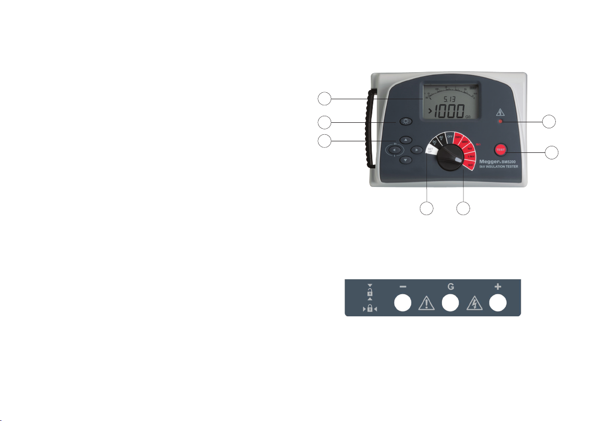
1. Backlit LCD display with analogue arc and dual 3-digit display.
2. Backlight on/off switch
3. Four arrow buttons, PI-t function on left arrow button
4. Main range switch Setup functions plus AC and DC voltmeter
(25 V to 600 V)
5. Main range switch with DC insulation tests at 250 V, 500 V,
1000 V, 2500 V and 5000 V.
6. TEST button to initiate and terminate insulation tests
7. Warning High Voltage (HV) indicator
1
2
3
7
6
Before switching on the BM5200 the test leads should be
connected to the instrument.
There are three test terminals marked +, - and G. These terminals
are designed to accept only the test leads supplied. Shutters across
the terminals prevent accidental ingress of dirt and other objects.
Test leads lock in the terminals to prevent accidental removal
during a test, rotate the plug until the locking action is engaged.
Terminal plugs can be removed by rotating through a quarter turn.
At the end of a test ensure that the voltage has decreased to a
safe value, i.e. <50 V, before removing the test leads. Reactive
loads may take some time to dissipate stored energy through the
instrument’s internal discharge resistors.
7
4
5
The BM5200 is turned on by rotating the main range switch to
insulation test, voltage test or setup function.
The terminals are located on a panel to the rear of the instrument
and marked +, - and G meaning Guard terminal.
Page 9
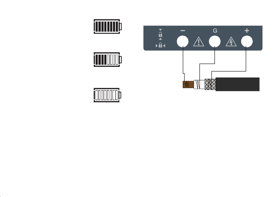
The battery level indicator is
located at the top right of the
display and contains four pairs of
segments depicting charge level.
Battery level indication of 50% of
battery life.
Battery level indication of a flat
battery.
Use of guard terminal (G)
For basic insulation resistance tests where there is little possibility
of surface leakage affecting the measurement, it is not necessary
to use the guard terminal i.e. if the insulator is clean and there
are unlikely to be any adverse current paths. However in cable
testing for example, there may be surface leakage paths across
the insulation between the bare cable and the external sheathing
due to the presence of moisture or dirt. To obtain an accurate
measurement, particularly at high testing voltages, a bare wire
may be bound tightly around the insulation and connected via the
third test lead to the guard terminal ‘G’.
As illustrated in the diagram, the guard terminal is at the same
potential as the negative terminal. Since the leakage resistance
is effectively in parallel with the resistance to be measured, the
use of the guard causes the current flowing through surface
leakage to be diverted from the measuring circuit. The instrument
therefore reads the leakage of the insulator, ignoring leakage
across its surface.
Setup procedure
The setup function is used to set the internal timer (t). Default
value is set at 1 minute and can be adjusted using the up and
down arrows. When the desired time setting is displayed the PI-t
(left
arrow) key is pressed and a beep confirms the new setting.
8
Page 10

Polarisation index (PI)
Polarisation Index (PI) test performs a test that calculates the
ratio of insulation resistance at ten minutes, IR
resistance at one minute, IR
indication of insulation polarisation when subjected to high
voltage DC. A high PI value indicates a high degree of insulation
polarisation and therefore good insulation condition. Generally the
PI value should be two or above.
Polarisation occurs at different rates ranging from minutes to
several hours which led the IEEE to create a ratiometric PI test. The
IEEE standard 43-2000, “Recommended Practice for Testing
Insulation Resistance of Rotating Machinery,” limits the use of PI
test on winding systems to those with IR
MΩ.
Timed insulation resistance
The timed IR test is a test that automatically terminates after a
user adjustable time (t). Users can select SETUP on the range
switch and adjust timer (t) using up and down arrow buttons to
set the desired time followed by a single press of the PI-t (left
arrow) button. Default time (t) is set at one minute because
IR1min is frequently referred to in international standards.
. This test provides a simple
1min
1min
to insulation
10 min
being less than 5000
Preventative maintenance
No user serviceable parts
There are no user serviceable parts in the BM5200 except for the
batteries.
If an instrument’s protection has been impaired it should not be
used, but sent for repair by suitably trained and qualified personnel.
The protection is likely to be impaired if for example, it shows
visible damage, fails to perform the intended measurements,
has been subjected to prolonged storage under unfavourable
conditions, or has been subjected to severe transport stresses.
Battery replacement
G WARNING
The battery contacts are not isolated from the test leads.
Remove the test leads from the instrument before opening
the battery compartment.
The cells are housed in a battery compartment in the base of the
instrument. To change the cells, use a PZ2 pozidrive screwdriver to
remove the battery cover securing screws and lift off the battery
compartment cover. Observing the correct polarity as marked on
the battery housing, install 8 replacement IEC LR6 (AA) cells.
Replace and secure the battery compartment cover on completion.
9
Page 11

Technical specifications
The following specifications apply at 20 °C unless otherwise
stated:
Electrical specifications
Insulation range 0.1 MΩ to 1 TΩ
Nominal test voltages 250 V, 500 V, 1000 V, 2500 V,
5000 V
Terminal voltage accuracy <1000 V 0 to 10% of nominal
test voltage
≥100 V 0 to +5% of nominal
test voltage
Insulation accuracy Up to 1 GΩ: All ranges ±5%
±2 digits
Over 1 GΩ:
5000 V ±5% ±0.04% per GΩ
2500 V ±5% ±0.08% per GΩ
1000 V ±5% ±0.2% per GΩ
500 V ±5% ±0.4% per GΩ
250 V ±5% ±0.8% per GΩ
Short circuit current 1.4 mA ±0.5 mA
Maximum load capacitance 5 μF
Voltmeter accuracy (DC or AC) 3% ±3 V
Frequency measurement 45 Hz to 65 Hz
Frequency accuracy ±2 Hz
Voltage range (DC or AC) 25 to 600 V AC or DC
Power supply 8 x LR6/AA batteries
Battery life 5 hours @ 5 kV into 100 MΩ
with AA Alkaline LR6
Guard 2% error guarding 5 MΩ leakage
on 100 MΩ load
Environmental specifications
Operating temperature range -20 ºC to +55 ºC
Operating humidity 90% RH, 0 ºC - 40 ºC
70% RH, 40 ºC - 55 ºC
Storage temperature -30 ºC to +65 ºC
Insulation protection IP40
Maximum Altitude 2000 m
Service error with stated environmental limits is twice intrinsic
error
Safety protection
Insulation CAT III 600 V - applicable standard IEC 61010-1:2001
Measurement Category III is applicable to test and measuring
circuits connected to the distribution part of the building’s lowvoltage mains installation. This part of the installation is expected
to have a minimum of two levels of over-current protective devices
between the transformer and possible connecting points.
EMC
The product conforms to IEC 61326-1:2005
Dimensions (W x H x D) 220 mm x 115 mm x 163 mm
Weight 1.45 kg
10
Page 12

Accessories
Replacement 3m x 3 leadset 1002-531
Repair and warranty
This instrument is not repairable. Should the instrument fail during the warranty period the instrument will be replaced by Megger.
New instruments are Guaranteed for 1 Year from the date of purchase by the User.
Note: Any unauthorised prior repair or adjustment will automatically invalidate the warranty.
This product contains no repairable parts and if defective it should be returned to your supplier in its original packaging or packed so
that it is protected from damage during transit.
11
Page 13

M
BM5200
Probador Digital de Aislamiento 5 kV
MANUAL DEL USUARIO
12
Page 14

CONTENIDO
Advertencias de seguridad ........................................................................................................................................................... 14
Símbolos usados en el instrumento ............................................................................................................................................... 15
Limpieza ................................................................................................................................................................................ 15
Descripción general ....................................................................................................................................................................... 16
Modos de prueba de la resistencia de aislamiento .................................................................................................................. 16
Descarga automática .............................................................................................................................................................. 16
Juego de cables ...................................................................................................................................................................... 16
Potencia del instrumento ........................................................................................................................................................ 16
Seguridad del instrumento .................................................................................................................................................... 17
Instrucciones de operación ............................................................................................................................................................ 17
Controles e indicadores del instrumento .......................................................................................................................................18
Instrument controls and indicators .......................................................................................................................................... 18
Uso del terminal de protección (G) .......................................................................................................................................... 19
Procedimiento de configuración ........................................................................................................................................................... 19
Índice de polarización (PI) ....................................................................................................................................................... 20
Resistencia sincronizada de aislamiento .................................................................................................................................. 20
Mantenimiento preventivo ............................................................................................................................................................ 20
Reemplazo de la batería ......................................................................................................................................................... 20
Especificación técnica ................................................................................................................................................................... 21
Reparación y garantía .................................................................................................................................................................. 22
13
Page 15

G ADVERTENCIAS DE SEGURIDAD
Advertencias de seguridad deben ser observadas durante el uso:
n El circuito bajo prueba debe ser apagado, descargado, aislado y verificado para la seguridad antes que las conexiones de la prueba sean hechas.
Asegúrese que el circuito no esté recargado mientras el instrumento sea conectado.
n Las conexiones del circuito no deben ser tocadas durante la prueba de aislamiento.
n Despues de completar la prueba, los circuitos de capacitivos deben estar completamente descargados antes de desconectar los cables de prueba. Las
cargas capacitivas puede ser mortales.
n Los objetos probados deben estar firmemente en corto, después de su descarga, hasta ser requeridos para su uso. Esto es para proteger contra
cualquier carga eléctrica almacenada que sea liberada posteriormente levantando el voltaje a niveles potencialmente peligrosos.
n El indicador de voltaje y las características automáticas de descarga deben ser considerados como característica adicional de seguridad y no un
sustituto de la práctica de seguridad laboral.
n Es raro, pero en ciertas circunstancias, una avería del circuito bajo prueba podría causar que el instrumento termine la prueba de una manera
incontrolable, causando posiblemente una pérdida de pantalla mientras el circuito se mantiene cargándose. En este evento, la unidad debe ser
apagada y el circuito debe ser cargado manualmente.
n Los cables de prueba, incluyendo las breves, deben estar en buena condición, limpios y sin un aislamiento roto o rajado.
n El instrumento no debe ser usado si alguna parte está dañada.
n La prueba de aislamiento en condiciones climáticas húmedas podría ser peligrosa. Se recomienda que este instrumento no sea usado en estas
circunstancias. Si esto es inevitable, el usuario debe tomar todas las precauciones necesarias.
n Este instrumento no es intrínsicamente seguro y no debe ser usado en atmósferas peligrosas.
n Si este equipo es usado en una manera no especificada por el fabricante, la protección proporcionada por el equipo puede ser perjudicada.
n Las baterías recargables no deben ser usadas en este instrumento.
NOTA
EL INSTRUMENTO DEBE SER USADO SOLO POR PERSONAS CONVENIENTEMENTE ENTRENADAS Y COMPETENTES.
A los usuarios de este equipo y/o a sus empleados se les recuerda que la legislación nacional de salud y seguridad requiere
que ellos realicen evaluaciones válidas de riesgos de todo trabajo eléctrico para identificar las fuentes potenciales de un
peligro eléctrico y el riesgo de lesiones eléctricas tales como cortocircuitos inadvertidos. Cuando las evaluaciones muestren
que el riesgo es significante entonces el uso conjunto de los cables de prueba podría ser apropiado.
14
Page 16

Símbolos usados en este instrumento
G Advertencia: refiérase a las notas que se incluyen
F Advertencia: riesgo de un eléctrico
t Clase II instrumento de doble aislamiento
No desheche en el servicio de desperdicios
El equipo cumple con las presentes directivas C-Tick australianas
+
Batería
Términos usados en este manual
La palabra debe se usa para indicar que las instrucciones que siguen deben ser seguidas bajo todas circunstancias. La falta de seguir
estas instrucciones podría resultar en daño al instrumento y/o un peligro al operador.
La palabra “puede” es usada para indicar que las instrucciones indican la mejor practica.
Limpieza
Desconecte el instrumento y límpielo con un paño limpio ligeramente húmedo con agua jabonosa o alcohol isopropilo (IPA).
15
Page 17

Descripción general
El probador de aislamiento BM5200 tiene una forma de arco
digital y análogo diseñado para la prueba de la resistencia de
aislamiento de alto voltaje en el mantenimiento y servicio de cables,
maquinaria giratoria de planta, transformadores, dispositivo de
distribución e instalaciones industriales.
Las pruebas de aislamiento DC son realizados a 250 V, 500 V,
1000 V, 2500 V y 5000 V. El rango de medición de la resistencia
de aislamiento es de 100 kQ a 1000 GΩ. La descarga automática
para los circuitos capacitivos bajo prueba se provee y la caída de
voltaje.
La terminal de protección puede ser usada para minimizar los
efectos de la fuga superficial y las medidas erróneas cuando se
realicen pruebas de resistencia de aislamiento.
Modos de prueba de la resistencia de aislamiento
Se proporcionan tres modos de prueba de la resistencia de
aislamiento, (InS, PI, t) y seleccionados de cualquier rango de
aislamiento al presionar la flecha izquierda con PI-t.
En los modos de prueba de la resistencia de aislamiento, las
pruebas son iniciadas al presionar y sostener el boton TEST
(prueba) por dos segundos. Una vez que la prueba de aislamiento
se ha iniciado, se terminara al presionarse nuevamente el botón
TEST (prueba). La lectura se mantiene en la pantalla hasta que el
botón TEST es presionado otra vez u otro rango sea seleccionado.
El modo del índice de polarización (PI) realiza una prueba
radiométrica que calcula la tasa de resistencia de aislamiento a los
diez minutos a la resistencia de aislamiento a un minuto.
El modo sincronizado (t) facilita una prueba única de duración fija
IR basado en un intervalo de tiempo fijo t.
Descarga automática
Para los objetos de prueba capacitiva, el instrumento descargará
automáticamente a través de un resistor interno e indicará el
voltaje a través de los terminales en el rango de 25 V a 600 V con
voltajes altos indicados por ‘>600 V’. Esta característica dará una
indicación de una caída de voltaje siguiendo la prueba del equipo
que posee capacitancia. Cuando el indicador de voltaje ya no
se muestra, es seguro para el usuario desconectar los cables de
prueba.
Juego de cables
Se suministra tres zócalos con entradas y marcados ‘+’, ‘-‘ y ‘G’.
Estos tienen tapas de seguridad que se abren cuando los enchufes
se introducen. Cuando se introducen en los zócalos, los enchufes
cubiertos de los cables de prueba se aseguran en posición. Se
sueltan al girar un cuarto el enchufe y jalar.
Por esta razón, solo los cables de prueba suministrados o repuestos
convenientes de Megger deberán ser usados.
16
Page 18

Potencia del instrumento
El BM5200 es operado con ocho baterías alkalinas 1.5 V IEC
LR6/AA
Seguridad del instrumento
Las características del diseño de seguridad incluyen:
n Indicador externo del voltaje, AC o DC en pantalla.
n Activa automáticamente la descarga al final de la prueba y la
caída de voltaje.
n Los cables de prueba pueden asegurarse en el estuche para
prevenir una desconexion accidental.
Preparación para su uso
1. Abra el paquete y ubique el instrumento BM5200, el estuche,
los cables de prueba, baterías, y las guías del usuario y de
inicio.
2. Asegúrese que el interruptor principal esté en posición de
apagado.
3. Localice el compartimento de la batería y ábrala usando un
destornillador PZ2 pozidrive.
4. Retire el módulo de baterías e introduzca las ocho baterías
alka linas 1.5 VLR6/AA asegurando la orientación correcta de
acuerdo a su polaridad.
5. Conecte el módulo de baterías al cable de la batería asegu
rando la polaridad correcta.
6. Regrese el módulo de baterías y su cubierta dentro de su
estuche y ponga los dos tornillos ajustándolos solo con la
mano.
7. Como revisión inicial, sin los cables conectados, encienda el
instrumento girando el interruptor principal a cualquie
posición diferente a apagado. Asegúrese que la pantalla del
instrumento funcione. Apague el instrumento. Si la pantalla del
instrumento no responde, vuelva al paso 2, repita el proceso y
verifique que las orientaciones de las ocho baterías estén
correctas.
8. Si el instrumento todavía falla en responder use un voltímetro
para revisar el voltaje del módulo de baterías el cual debe ser
12 V asumiendo que todas las pilas estén a su nivel 1.5 V.
17
Page 19

Instrucciones de operación
Controles e indicadores del instrumento
1. Pantalla retroiluminada LCD con arco análogo y pantalla doble
de 3 dígitos.
2. Interruptor iluminado de encedido y apagado.
3. Cuatro botones de flechas, función PI-t en el botón con la
flecha a la izquierda
4. Funciones de instalación del interruptor principal más voltímetro
AC y DC (25 V a 600 V)
5. Interruptor principal con prueba de aislamiento DC a 250 V,
500 V, 1000 V, 2500 V y 5000 V.
6. Botón TEST para iniciar y terminar las pruebas de aislamiento.
7. Indicador de advertencia de alto voltaje (HV)
Antes de encender el BM5200 los cables de prueba deben estar
conectados al instrumento.
Hay tres terminales de pruebas marcadas +, - y G. Estos terminales
están diseñados para aceptar solo los cables de prueba suministradas.
Las protecciones de los terminales previenen el ingreso accidental de
polvo y otros objetos. El bloqueo de los conectores en los bornes
sirven para prevenir de extracciones accidentales durante una
prueba y se activan girando el tapón mediante una rotación a
través con un cuarto de vuelta.
Al final de una prueba debe asegurarse que la tensión ha
disminuido a un valor seguro, por ejemplo <50 V antes de retirar
los conectores. Las cargas reactivas pueden tardar cierto tiempo
en descargarse.
1
2
3
4
5
7
6
El BM5200 se enciende girando el interruptor principal a la prueba
de aislamiento, prueba de voltaje o función de iniciación.
Los bornes están localizados en la parte trasera del equipo y está
indicada con el signo + y -. El símbolo G significa borne protegido.
18
Page 20

El indicador del nivel de la batería está
localizado en la parte superior derecha
de la pantalla y contiene cuatro pares
de segmentos que muestran el nivel de
cargado.
La indicación del nivel de cargado a un
50% de la vida de la batería.
La indicación del nivel de una batería
baja.
Uso del terminal de protección (G)
Para pruebas básicas de la resistencia de aislamiento dond hay una
pequeña posibilidad de fuga superficial que afecte la medición,
no es necesario usar el terminal de protección. Por ejemplo, si
el aislador está limpio y es poco probable tener alguna corriente
adversa. Sin embargo en prueba de cableado por ejemplo, podría
haber fugas superficiales en el aislamiento entre el cable pelado y
el revestimiento externo debido a la presencia de húmeda o polvo.
Para obtener una medición exacta, particularmente en pruebas
de altos voltajes, un alambre pelado podría sujetarse duramente
alrededor del aislamiento y conectarse via el tercer cable de
prueba al terminal de protección ‘G”.
19
Como se ilustra en el diagrama, el terminal de protección está al
mismo potencial como el terminal negativo. Como la resistencia
de fuga está efectivamente en paralelo con la resistencia a ser
medida, el uso de la protección causa que la corriente en la
fuga superficial sea desviada del circuito medido. El instrumento
entonces lee la fuga del aislador, ignorando la fuga en la
superficie.
Procedimiento de configuración
La función de configuración se usa para configurar el temporizador
interno (t). El valor por defecto es de 1 minuto y se puede ajustar
con las flechas hacia arriba y hacia abajo. Cuando aparezca la
configuración de tiempo deseada se presiona la tecla Pl-t (flecha
izquierda) y un pitido confirmará la nueva configuración.
Page 21

Índice de polarización (PI)
La prueba de índice de polarización (PI) realiza una prueba métrica
de relación que calcula la tasa de resistencia de aislamiento a los
diez minutos, IR
IR
.
1min
Esta prueba suministra una indicación simple de polarización de
aislamiento cuando está sujeta a un alto voltaje DC. Un valor alto
PI indica un alto grado de polarización de aislamiento y por lo
tanto una buena condición de aislamiento. Generalmente el valor
de PI debe ser dos o más.
La polarización ocurre a ritmos diferentes que van desde minutos
a varias horas que lleva al IEEE crear una prueba radiométrica PI.
El normal IEEE 43-2000, “Práctica recomendada para la prueba de
resistencia de aislamiento de maquinaria rotativa,” limita el uso
de la prueba PI a sistemas de bobinas a aquellas con IR
menos de 5000 MΩ.
Resistencia sincronizada de aislamiento
La prueba sincronizada IR es una prueba que automáticamente
termina a un tiempo ajustable del usuario (t). Los usuarios pueden
seleccionar SETUP (configuración) en el rango del interruptor y
ajustar el reloj (t) usando los botones de flechas de arriba y abajo
para fijar el tiempo deseado seguido con la presión del botón de
flecha a la izquierda PI-t. El tiempo pre-determinado (t) está fijado
a un minuto porque IR 1 min es con frecuencia referido a normas
internacionales.
a la resistencia de aislamiento a un minuto,
10min
1min
siendo
Mantenimiento preventivo
No hay partes de repuesto al usuario
No hay partes de repuesto al usuario en el BM5200 con excepción
de las baterías.
Si la protección de un instrumento ha sido deteriorada, no
debe ser usado pero envíado para reparación por personal
convenientemente entrenado y calificado. La protección está
probablemente deteriorada si por ejemplo, muestra daños
visibles, falla en realizar la medida prevista, ha sido sujeta a un
almacenamiento prolongado bajo condiciones desfavorables, o ha
sido sujeto a un severo mal transporte.
Reemplazo de las baterias
G Advertencia
Los contactos de las baterías no están aislados de los cables de
prueba. Quite los cables de prueba del instrumento antes de
abrir el compartimento de la batería.
Las pilas están alojadas en un compartimento de baterías en la
base del instrumento. Para cambiar las pilas, use un desarmador
pozidrive PZ2 para quitar la cubierta de la batería asegurando los
tornillos y levante la cubierta del compartimento de la batería.
Observe la polaridad correcta como está marcada en la estructura,
instale 8 pilas IEC LR6 (AA).
Vuelva a colocar la cubierta del compartimento de la batería y
asegúrela a su cierre.
20
Page 22

Especificaciones técnicas
Las siguientes especificaciones se aplican a 20 °C a menos que
algo diferente se indique:
Especificaciones eléctricas
Rango del aislamiento 0.1 MΩ a 1 TΩ
Voltajes nominales de prueba 250 V, 500 V, 1000 V, 2500 V,
5000 V
Exactitud terminal de voltaje <1000 V 0 a +10% del voltaje
nominal de prueba
≥100 V 0 to +5% del voltaje
nominal de prueba
Exactitud de aislamiento hasta 1 GΩ:
Todos los rangos ±5% ±2 dígitos
Por encima 1 GΩ: 5000 V ±5% ±0.04% por GΩ
2500 V ±5% ±0.08% por GΩ
1000 V ±5% ±0.2% por GΩ
500 V ±5% ±0.4% por GΩ
250 V ±5% ±0.8% por GΩ
Presente corto circuito 1.4 mA ± 0.5 mA
Máxima capacitancia de carga 5 μF
Exactitud del voltímetro (DC o AC) 3% ±3 V
Medición de frecuencia 45 Hz a 65 Hz
Exactitud de frecuencia ±2 Hz
Rango de voltaje (DC o AC) 25 a 600 V AC o DC
Protección con error de 2% protegiendo 5 MΩ derrame en una
carga de 100 MΩ
Especificaciones ambientales
Rango de temperatura de operación
-20 ºC a +55 ºC
Humedad de operación 90% RH, 0 ºC - 40 ºC
70% RH, 40 ºC - 55 ºC
Temperatura de almacenamiento -30 ºC a +65 ºC
Protección del aislamiento IP40
Altitud máxima 2000 m
Error en el servicio con límites ambientales establecidos es un
error intrínseco doble
Protección de seguridad
Aislamiento CAT III 600 V - IEC61010-1:2001 estándar aplicable
La medición de la categoría III es aplicable a la prueba y a la
medición de los circuitos conectados a la instalación de la red
a bajo voltaje de la parte de distribución del edificio. Esta parte
de instalación se espera que tenga un nínimo de dos niveles de
dispositivos protectivos de sobrecorriente entre el transformador y
puntos posibles de conexión.
Fuente de alimentación 8 x LR6/AA baterías
Duración de batería 5 horas @ 5 kV en 100 MΩ con
AA Alkalina LR6
21
Page 23

EMC
El producto se ajusta a IEC 61326
Dimensiones (Ancho x Alto x Largo)
220 mm x 115 mm x 163 mm
Peso 1.45 kg
Accesorios
Cables de repuesto 3 m x 3 1002-531
Reparación y garantía
Este instrumento no puede repararse. En caso de fallas dentro del período de garantía, el instrumento será sustituido por Megger.
Los nuevos instrumentos están garantizados por 1 año desde la fecha de compra por el usuario.
Nota: Cualquier reparación previa no autorizada o ajuste invalidará automáticamente la garantía.
Este producto contiene partes no reparables y si está defectuoso debe ser devuelto a su proveedor en la envoltura original o empaquetado
de manera que esté protegido de daños durante tránsito.
22
Page 24

23
Page 25

M
BM5200
Provador Digital de Isolamento 5 kV
MANUAL DO UTILIZADOR
24
Page 26

ÍNDICE
Avisos de segurança ....................................................................................................................................................................... 26
Os símbolos usados no instrumento ............................................................................................................................................... 27
Limpeza .................................................................................................................................................................................. 27
Descrição geral .............................................................................................................................................................................. 28
Modos de teste da resistência de isolamento .......................................................................................................................... 28
Descarga automática ............................................................................................................................................................... 28
Conjunto de cabos .................................................................................................................................................................. 28
Potência do Instrumento ......................................................................................................................................................... 28
Segurança do instrumento ..................................................................................................................................................... 28
Preparação para uso ...................................................................................................................................................................... 29
Instruções de uso ........................................................................................................................................................................... 29
Controles e indicadores do instrumento ................................................................................................................................. 29
Utilização do terminal de proteção (G) .................................................................................................................................... 30
Índice de polarização (PI) ......................................................................................................................................................... 31
Resistência de isolamento cronometrada ................................................................................................................................. 31
Procedimento de configuração ................................................................................................................................................ 31
Manutenção preventiva ................................................................................................................................................................. 32
Substituição das pilhas ............................................................................................................................................................ 32
Especificações técnicas ................................................................................................................................................................... 32
Reparação e garantia ..................................................................................................................................................................... 34
25
Page 27

G AVISOS DE SEGURANÇA
O aviso de segurança deve ser observado durante a utilização:
n O circuito sob teste deve estar desligado, desativado, isolado e controlado para ser seguro, antes que as conexões de teste de isolamento
sejam feitas. Certifique-se que o circuito não está reativado enquanto o instrumento está ligado.
n As conexões do circuito não devem ser tocadas durante um teste de isolamento.
n Depois de completar um teste, os circuitos capacitivos devem estar totalmente descarregados antes de desconectar os cabos de teste. As des
cargas capacitivas podem ser mortais.
n Os objetos provados devem estar firmemente em curto-circuito, com uma ligaçação de curto-circuito, após a descarga, até à utilização. Isto
é para proteger contra qualquer absorção dielétrica armazenada, que seja posteriormente liberada, aumentando assim, a tensão a níveis po
tencialmente perigosos.
n O indicador de tensão, e as características de descarga automática, devem ser consideradas como recursos de segurança adicionais, e não
um substituto para a prática normal de segurança no trabalho.
n É raro, mas em certas circunstâncias, uma avaria do circuito sob teste pode fazer com que o instrumento termine o teste numa maneira
descontrolada, possívelmente causando uma perda de visor, enquanto o circuito continua energizado. Neste caso, o aparelho deve ser
desligado e o circuito descarregado manualmente.
n Os cabos de teste, incluindo os clipes de crocodilo, devem estar em boas condições, limpos e sem isolamento quebrado ou rachado.
n O instrumento não deve ser usado se qualquer parte estiver danificada.
n Testes de isolamento em condições chuvosas podem ser perigosos. Recomenda-se que este instrumento não seja utilizado nessas circunstâncias.
Se isso fôr inevitável, o utilizador deve tomar todas as precauções necessárias.
n Este instrumento não é intrinsecamente seguro e não deve ser utilizado em atmosferas perigrosas.
n Se este equipamento é usado numa maneira não especificado pelo fabricante, a proteção fornecida pelo equipamento pode ser comprometida.
n As baterias recarregáveis não devem ser utilizadas neste instrumento.
NOTA
O INSTRUMENTO DEVE SER UTILIZADO ÚNICAMENTE POR PESSOAS COMPETENTES E DEVIDAMENTE TREINADAS.
Aos utilizadores deste equipamento e/ou aos seus empregadores faz-se lembrar de que a Legislação Nacional de Saúde e Segurança obriga-os
a realizar avaliações válidas de risco de todos os trabalhos eléctricos, de modo a identificar potenciais fontes de perigo elétrico, e o risco de
lesões elétricas, tais como curto-circuitos acidentais. Quando as avaliações mostram que o risco é significativo, a utilização de cabos de teste
acoplados pode ser apropriada.
26
Page 28

Os símbolos utilizados neste instrumento
G Cuidado: verifique as notas explicativas incluidas
F Cuidado: risco de choque elétrico
t Classe II instrumento de isolamento duplo
Não descarte no serviço de resíduos
O equipamento está em conformidade com as actuais directivas C-Tick Australianas
+
Pilha
Termos usados neste manual
A palavra deve é usada para indicar que as instruções seguintes devem ser seguidas em todas as circunstâncias. O não cumprimento
destas instruções pode resultar em danos no instrumento e/ou perigo para o utilizador.
A palavra ‘deve’ é usada para indicar que as instruções indicam a melhor prática.
Limpeza
Desligue o aparelho e limpe-o com um pano limpo, levemente umedecido com água e sabão ou álcool isopropílico (IPA).
27
Page 29

Descrição geral
O provador de isolamento BM5200 tem um visor digital e arco
analógico desenhado para testar a resistência de isolamento de
alta tensão na manutenção e reparação de cabos, máquinas
rotativas instaladas, transformadores, interruptores e instalações
industriais.
Os testes de isolamento DC são realizados a 250 V, 500 V, 1000 V,
2500 V e 5000 V. A faixa de medição da resistência de isolamento
é de 100 kΩ a 1000 GΩ. A descarga automática para circuitos
capacitivos em teste é fornecida e a tensão decadente é exibida.
O terminal de proteção pode ser usado para minimizar os efeitos
da fuga de superfície e, portanto, as medidas erradas aquando da
realização de testes de resistência de isolamento.
Modos de teste da resistência de isolamento
São fornecidos três modos de teste da resistência de isolamente
(IR), (InS, PI, t) e selecionados a partir de qualquer faixa
de isolamento, pressionando a tecla em seta na esquerda
representando PI-t.
Em modo de teste da resistência de isolamento (InS) os testes
são iniciados pressionando e segurando o botão TEST (teste)
durante dois segundos. Uma vez que um teste de isolamento
tenha começado, terminará na próxima pressão do botão de TEST
(teste). A leitura é mantida no visor até que o TEST é pressionado
novamente ou outra faixa seja selecionada.
Um modo de Indice de Polarização (PI) realiza um teste ratiometric
que calcula a relação entre a resistência de isolamento a dez
minutos à resistência de isolamento a um minuto.
O modo de cronômetro (t) facilita um teste único de duração fixa
IR com base no intervalo de tempo estabelecido t.
Descarga automática
Para objetos de teste capacitivo o instrumento descarregará automaticamente através de um resistor interno e indicará a tensão
através dos terminais na faixa de 25 V e 600 V com tensões mais
altas indicadas por ‘> 600 V ‘. Esta caracteristica dará uma indicação
de uma descida de tensão após o teste do equipamento que possui
capacitância. Quando o indicador de tensão já não aparece, é
seguro para o utilizador desligar os cabos de teste.
Conjunto de cabos
São fornecidas três tomadas com recesso, e marcadas ‘+’, ‘-’ e ‘G’.
Estas têm tampas de segurança que se abrem quando as fichas
estão inseridas. Quando inseridas nas tomadas, os cabos cobertos
das fichas de teste ficam seguros na posição. Eles são libertos
torcendo a ficha um quarto de volta e puxando para fora.
Por esta razão, apenas os cabos de teste fornecidos ou os
substitutos adequados da Megger devem ser usados.
Energia para o instrumento
O BM5200 é alimentado por oito pilhas alcalinas 1,5 V IEC LR6/
AA.
As baterias recarregáveis não devem ser utilizadas neste instrumento.
Segurança do instrumento
As características do desenho de segurança incluem:
n Indicação de tensão externa, AC ou DC exibida.
28
Page 30

n A carga é automaticamente descarregada no final de um teste,
e a tensão decadente é exibida.
n Os cabos de teste podem ficar seguros na caixa para evitar descon
exão acidental.
Preparações para utilização
1. Abra a caixa e localize o instrumento BM5200, bolsa de trans
porte, cabos de teste, pilhas, e guias de início rápido e do
utilizador.
2. Certifique-se que a faixa do interruptor principal está na
posição OFF.
3. Localize o compartimento das pilhas e abra-o usando uma
chave de fendas PZ2 pozidrive.
4. Remova o módulo das pilhas e introduza as oito pilhas alcalinas
1,5 VLR6/AA, assegurando-se da orientação correta de acordo
com a sua polaridade.
5. Ligue o módulo das pilhas ao cabo das pilhas assegurando-se
que a polaridade está correta.
6. Reponha o módulo e a tampa das pilhas na caixa e recoloque
os dois parafusos apertando sòmente à mão.
7. Como verificação inicial, sem quaisquer cabos conectados,
ligue o instrumento girando a faixa do interruptor principal
para qualquer outra posição além de OFF. Certifique-se que o
visor do instrumento funciona. Desligue o instrumento. Se o
visor do instrumento não responder, retorne à etapa 2, repita o
processo e verifique que todas as orientações das oito pilhas
estão corretas.
8. Se o instrumento ainda não responder, use um voltímetro para
verificar a voltagem do módulo das pilhas que deverá ser de
29
Instruções de utilização
Controles e indicadores do instrumento
1. Visor em contraluz LCD com arco analógico duplo de 3 dígitos.
2. Interruptor iluminado de ligar/desligar
3. Quatro botões de setas, a função PI-t no botão de seta à
esquerda
4. Organização das funções do interruptor principal mais
voltímetro AC e DC (25 V e 600 V)
5. Faixa do interruptor principal com testes de isolamento DC a
250 V, 500 V, 1000 V, 2500 V e 5000 V.
6. Botão TEST para iniciar e terminar os testes de isolamento
7. Indicador de aviso de Alta Tensão (HV),
Antes de ligar o BM5200 os cabos de teste devem estar
conectados ao instrumento.
Existem três terminais de teste marcados +, - e G. Estes terminais
são desenhados para aceitar apenas as cabos de teste fornecidos.
Obturadores nos terminais evitam a entrada acidental de sujidade
e outros objetos. Os cabos de teste trancam no terminal, para
evitar que se desliguem acidentalmente durante o teste. Este
bloqueio consegue-se rodando a fixa até ativar o mecanismo de
engrenagem. Ficha pode ser removida rodando novamente de
volta.
NO final do teste certificar que a voltagem foi descarregada e que
passou para valores de segurança, i.e. <50 V, antes de remover os
cabos de teste. Cargas reativas podem levar algum tempo a
dissipar a energia acumulada, através dos componentes internos
de descarga residual.
Page 31

O indicador do nível das pilhas está
localizado no canto superior direito
do ecrã e contém quatro pares de
segmentos que mostram o nível
de carga.
1
2
3
4
5
7
6
O BM5200 liga-se girando a faixa do interruptor principal para
teste de isolamento, teste de tensão ou função de configuração.
Os terminais são trancados no painel situado na traseira do
equipamento e sinalizado com sinal “+”, - “G” significa terminal
protegido.
Indicação do nível de 50% de vida
útil da pilha.
Indicação do nível de uma
bateria descarregada.
Utilização do terminal de proteção (G)
Para os testes de resistência de isolamento de base, onde há
pouca possibilidade de fuga de superfície que afecte a medição,
não é necessário usar o terminal de proteção, isto é, se o isolador
está limpo e que não seja provável haver caminhos de corrente
adversos. No entanto, por exemplo, no teste de cabo, pode
haver fugas de superfície através do isolamento, entre o cabo
descoberto e o
invólucro externo, devido à presença de humidade ou sujidade.
Para obter uma medida precisa, especialmente em testes de alta
tensão, um arame descoberto pode ser ligado firmemente em
torno do isolamento e conectado, por via do terceiro cabo de
teste, ao terminal de proteção ‘G’.
30
Page 32

Como ilustrado no diagrama, o terminal de proteção está ao
mesmo potencial que o terminal negativo. Uma vez que a
resistência de fuga está efetivamente em paralelo com a
resistência a ser medida, o uso da proteção faz com que a
corrente, que flui através de fugas de superfície, seja desviada
do circuito de medição. O instrumento, portanto, lê a fuga do
isolador, ignorando fugas na sua superfície
Procedimento de configuração
A função de configuração é usada para definir o marcador de
tempo interno (t). O valor padrão é de 1 minuto e pode ser
ajustado usando as setas para cima e para baixo. Quando o ajuste
do tempo desejado é mostrado, a tecla PI-t (seta para a esquerda)
é pressionada e um sinal sonoro confirma a nova configuração.
31
Índice de Polarização (PI)
O teste de Índice de Polarização (PI) realiza um teste da razão
métrica que calcula a relação entre a resistência de isolamento
a dez minutos, IR
minuto, IR
1min
.
Este teste fornece uma indicação simples de polarização de
isolamento quando submetido a alta tensão DC. Um valor elevado
PI indica um alto grau de polarização de isolamento e, portanto,
uma boa condição de isolamento. Geralmente o valor de PI deve
ser de dois ou mais.
A polarização ocorre a taxas diferentes, que variam de minutos
a várias horas, o que levou a IEEE a criar um teste ratiometric PI.
O padrão 43-2000 IEEE, “Práticas Recomendadas para Testes
de Resistência de Isolamento de Máquinas Rotativas”, limita a
utilização do teste de PI em sistemas de bobinagem aos que IR
seja inferior a 5000 MΩ.
Resistência de isolamento cronometrada
O teste cronometrado IR é um teste que termina automaticamente
depois do tempo ajustável (t) pelo utilizador. Os utilizadores
podem selecionar SETUP (configuração)na faixa do interruptor e
ajustar o cronômetro (t), utilizando teclas de seta de para cima
e para baixo, para definir o tempo desejado, seguido por uma
simples pressão do botão PI-t (seta à esquerda). O tempo padrão
(t) está fixado a um minuto, porque IR1min é frequentemente
referido nas normas internacionais.
min e a resistência de isolamento a um
10min
1min
Page 33

Manutenção preventiva
Não há peças reparáveis pelo utilizador
Não existem peças reparáveis pelo utilizador no BM5200, exceto
as pilhas.
Se a proteção de um instrumento foi danificada, não deve ser
usado, mas enviado para reparação por pessoal devidamente
treinado e qualificado. A proteção é susceptível de estar
danificada se, por exemplo, mostra danos visíveis, não executa as
medidas previstas, foi submetido a armazenamento prolongado
em condições
desfavoráveis, ou que tenha sido submetido a condições
deficientes durante o transporte.
Substituição das pilhas
G AVISO
Os contatos das pilhas não estão isoladas dos cabos de teste.
Retire os cabos de teste do instrumento antes de abrir o
compartimento das pilhas.
As pilhas estão alojadas num compartimento na base do
instrumento. Para trocar as pilhas, use uma chave de fendas PZ2
pozidrive para remover os parafusos que seguram a tampa e retire
a tampa do compartimento das pilhas. Verificando a polaridade
correta indicada no compartimento das pilhas, instale 8 pilhas de
substituição IEC LR6 (AA).
Ao concluir, aparafuse a tampa do compartimento das pilhas.
Especificações técnicas
As especificações seguintes aplicam-se a 20 ° C, salvo indicação
em contrário:
Especificações elétricas
Faixa de isolamento 0,1 MΩ a 1 MΩ TΩ
Tensões nominais de teste 250 V, 500 V, 1000 V, 2500 V,
5000 V
Precisão do terminal de tensão <1000 V 0 a +10% da tensão
nominal de teste
≥100 V 0 a +5% da tensão
nominal de teste
Precisão do isolamento
Até 1 GΩ: Todas as faixas ±5%
±2 dígitos
Mais de 1 GΩ:
5000 V ±5% ± 0,04% por GΩ
2,500 V ±5% ± 0,08% por GΩ
1000 V ±5% ± 0,2% por GΩ
500 V ±5% ± 0,4% por GΩ
250 V ±5% ± 0,8% por GΩ
Corrente de curto-circuito 1,4 mA ± 0,5 mA
Capacidade máxima de carga 5 μF
Precisão do voltímetro (DC ou AC) 3% ±3 V
Medição de frequência 45 Hz a 65 Hz
Precisão da frequência ±2 Hz
Faixa de tensão (DC ou AC) 25 a 600 V AC ou DC
32
Page 34

Fonte de alimentação 8 x pilhas LR6/AA
Duração da pilha com Proteção 5 horas a 5 kV em 100 MΩ
AA alcalinas LR6
2% de erro na proteção de fugas
de 5 MΩ em carga de 100 MΩ
Especificações ambientais
Faixa de temperatura de operação
-20 ºC a +55 ºC
Umidade de operação 90% RH, 0 ºC - 40 ºC
70% RH, 40 ºC - 55 ºC
Temperatura de armazenamento -30 ºC a +65 ºC
Protecção dei solamento IP40
Altitude Máxima 2000 m
O erro de serviço com limites ambientais estabelecidos é o dobro
do erro intrínseco
Protecção de segurança
Isolamento CAT III 600 V - IEC61010-1:2001
A medição de Categoria III, é aplicável para testar os circuitos
de medição, ligados aos canais da instalação eléctrica de baixa
tensão, no local de distribuição do edifício,. Esta parte da
instalação, deverá ter um mínimo de dois níveis de dispositivos
de protecção de excesso de corrente, entre o transformador e os
possíveis pontos de conexão.
Dimensões (Ancho x Alto x Largo)
220 mm x 115 mm x 163 mm
Peso 1.45 kg
EMC
O produto está em conformidade com IEC 61326
33
Page 35

Acessórios
Cabo de substituição leva 3 x 3m
Reparação e garantia
Este equipamento não é reparável. Se o equipamento falhou durante o período de garantia, o mesmo será substituído pela Megger.
Instrumentos novos estão garantidos por 1 ano a contar da data da compra pelo utilizador.
Nota: Qualquer reparação ou ajuste prévios não autorizados invalidam automaticamente a garantia.
Este produto não contém peças reparáveis e em caso de defeito deverá ser devolvido ao seu fornecedor na embalagem original ou
acondicionado de modo que seja protegido de danos durante o transporte.
34
Page 36

M
Megger Limited
Archcliffe Road, Dover
Kent CT17 9EN England
T +44 (0)1 304 502101
F +44 (0)1 304 207342
E uksales@megger.com
Megger
Valley Forge Corporate Centre
2621 Van Buren Avenue
Norristown, PA 19403 USA
T +1 610 676 8500
F +1 610-676-8610
E ussales@megger.com
Megger
501 Crystal Paradise Mall
Off Veera Desai Road
Andheri(w), Mumbai - 400053
Maharashtra
India
T +91 22 26740468
F +91 22 26740465
This instrument is manufactured in the United Kingdom.
The company reserves the right to change the specification or design without prior notice.
Megger is a registered trademark
Printed in the UK
Part No. BM5200--2001-444_UG_en-es-pt_V06
www.megger.com
Megger Sweden AB
Eldarvägen 4
Box 2970
SE-187 29 TÄBY
Sweden
T +46 8 510 195 00
F +46 8 510 195 95
Megger Pty Limited
Unit 26 9 Hudson Avenue
Castle Hill
Sydney NSW 2125 Australia
T +61 (0)2 9659 2005
F +61 (0)2 9659 2201
E ausales@megger.com
 Loading...