

Page 1

M
AVO300 Series
Digital Multimeters
USER MANUAL
MANUAL DE L’UTILISATEUR
BEDIENUNGSANLEITUNG
MANUAL DEL USUARIO
Page 2

GSAFETY WARNINGS
The following safety information must be observed to insure maximum personal safety during the operation at this meter:
■ Do not use in wet environments
■ Measurements beyond the maximum selected range must not be attempted.
■ Extreme care must be taken when measuring above 50 V, especially on live bus-bars.
■ To measure voltage, the instrument must not be switched to a current or resistance range, or to the diode check or buzzer position.
■ Circuits must be de-energised and isolated before carrying out resistance tests.
■ The rotary selector switch must only be turned after removing test connections.
■ All external voltages must be disconnected from the instrument before removing the battery.
■ Test leads and prods must be in good order, clean, and with no broken or cracked insulation.
■ UK Safety Authorities recommend the use of fused test leads when measuring voltage on high energy systems.
■ Replacement fuses must be of the correct type and rating.
■ The instrument must not be used if any part of it is damaged.
■ Check for correct instrument operation by testing a known voltage before and after use. Do not use if misleading results are obtained.
■ Warnings and precautions must be read and understood before an instrument is used. They must be observed during the operation of this instrument.
2
Users of this equipment and/or their employers are reminded that National Health and Safety Legislation requires them to carry out valid risk assessments of
all electrical work so as to identify potential sources of electrical danger and risk of electrical injury such as inadvertent short circuits. Where the assessments
show that the risk is significant then the use of fused test leads may be appropriate.
NOTE
THE INSTRUMENT MUST ONLY BE USED BY SUITABLY TRAINED AND COMPETENT PERSONS.
Page 3
Symbols used on the instrument are:
F Caution: risk of electric shock
G Caution: refer to accompanying notes
t Equipment protected throughout by Double
Insulation (Class II))
c Equipment complies with current EU directives.
Equipment complies with ‘C tick’ requirements
CONTENTS
3
Introduction 4
Symbols and annuniciators 4
Operation 4
Mode button 4
Hold button 4
Backlight button (AVO310 only) 4
Max/Min button (AVO310 only) 5
DC Voltage measurements 5
AC Voltage measurements 5
DC Current measurement 5
AC Current measurement 5
Resistance [Ω] measurement 6
Continuity check 6
Diode test 6
Specifications 7
Battery and fuse replacement 10
Battery installation 10
Replacing the fuses 10
Accessories 11
Repairs and warranty 12
MANUAL DE L’UTILISATEUR 13
BEDIENUNGSANLEITUNG 27
MANUAL DEL USUARIO 41
N13117
Page 4
To turn on the instrument turn the range knob from the OFF position to
any measurement range.
Note: For best battery life ALWAYS turn the function switch to the OFF
position when the meter is not in use. These meters have an Auto OFF
that automatically shuts the meter OFF if left switched on. AVO300:15
minutes, AVO310: 30 minutes.
Note: On some low AC and DC voltage ranges, with the test leads not
connected to a device, the display may show a random, changing reading.
This is normal and is caused by the high-input sensitivity. The reading will
stabilize and give a proper measurement when connected to a circuit.
MODE button
To select AC or DC measurement when in Amps, mA or uA ranges.
HOLD button
The HOLD function allows the meter to "freeze" a measurement for later
reference.
1. Press the HOLD button to "freeze" the reading on the indicator. The
"HOLD" message will be appear in the display.
2. Press the HOLD button again to return to normal operation.
BACKLIGHT button (AVO310 only)
1. Press the BACKLIGHT button to switch on the display light.
2. Press the BACKLIGHT button again to exit the light mode.
INTRODUCTION OPERATION
4
Thank you for purchasing one of the Megger AVO300 series digital
multimeters.
For your own safety and to get the maximum benefit from your
instrument, please ensure that you read and understand the following
safety warnings and instructions before attempting to use the instrument.
This user guide describes the operation and functions of the following
AVO300 series of digital multimeters.
AVO300
AVO310
SYMBOLS AND ANNUNCIATORS
Continuity
BAT Low Battery
Diode test
HOLD Data Hold
AUTO AutoRanging
AC Alternating Current or Voltage
DC Direct Current or Voltage
MAX/MIN Stores the highest or lowest measurement
Backlight
V Volts
A, mA, uA Current range
Page 5

decimal point, value and symbol (AC, V, etc.).
DC CURRENT MEASUREMENT
CAUTION: Do not make current measurements on the 10A scale for
longer than 30 seconds. Exceeding 30 seconds may cause damage to the
meter and/or the test leads.
1. Insert the black test lead plug into the negative (COM) jack.
2. For current measurements up to 4000 µA DC, set the function switch to
the uA position and insert the red test lead plug into the (µA) jack.
3. For current measurements up to 400 mA DC, set the function switch to
the mA range and insert the red test lead plug into the (mA) jack.
4. For current measurements up to 10 A DC, set the function switch to the
A position and insert the red test lead plug into the 10 A jack.
5. Press the AC/DC button until "DC" appears in the display.
6. Remove power from the circuit under test, then open up the circuit at
the point where you wish to measure current.
7. Connect the black test probe to the negative side of the circuit. Connect
the red test probe to the positive side of the circuit.
8. Apply power to the circuit.
9. Read the current in the display. The display will indicate the proper
decimal point, value and symbol.
10. Remove power from circuit before disconnecting test leads
5
MAX/MIN button (AVO310 only)
The MAX/MIN function allows the meter to capture the highest or lowest
measurement for later reference.
1. Press the MAX/MIN button to begin measurement. The indicator "MAX"
or MIN will appear in the display.
2. If the "MAX MIN" messages are flashing, the instrument is in MAX/MIN
mode but not recording, press the MAX/MIN button to select a mode.
3. To return to normal AUTO measurement mode, hold down the
MAX/MIN button for 2 seconds.
DC VOLTAGE MEASUREMENTS
1. Set the function switch to the V DC position ("mV" will appear in the
display).
2. Insert the black test lead plug into the negative (COM) jack and the red
test lead plug into the positive (V) jack.
3. Connect the test probe tips to the circuit under test. Be sure to observe
the correct polarity (red lead to positive, black lead to negative).
4. Read the voltage in the display. The display will indicate the proper
decimal point and value. If the polarity is reversed, the display will show
(-) minus before the value.
AC VOLTAGE MEASUREMENTS
1. Set the function switch to the V AC position.
2. Insert the black test lead plug into the negative (COM) jack and the red
test lead plug into the positive (V) jack.
3. Connect the test probe tips to the circuit under test.
4. Read the voltage in the display. The display will indicate the proper
Page 6

6
AC CURRENT MEASUREMENT
CAUTION: Do not make current measurements on the 10 A scale for
longer than 30 seconds. Exceeding 30 seconds may cause damage to the
meter and/or the test leads.
1. Insert the black test lead plug into the negative (COM) socket.
2. For current measurements up to 10 A, set the function switch to the A
position and insert the red test lead plug into the (10 A) jack.
3. For current measurements up to 400 mA, set the function switch to the
mA range and insert the red test lead plug into the (mA) jack.
4. For current measurements up to 10 A AC, set the function switch to the
A position and insert the red test lead plug into the 10 A jack.
5. Press the MODE button. The measurement mode will change between
AC or DC as required.
6. Remove power from the circuit under test, then open up the circuit at
the point where you wish to measure current.
7. Connect the black test probe to the negative side of the circuit. Connect
the red test probe to the positive side of the circuit.
8. Apply power to the circuit. Read the current in the display. The display
will indicate the proper decimal point, value and symbol.
11. Remove power from circuit before disconnecting test leads
RESISTANCE [Ω] MEASUREMENT
WARNING: To avoid electric shock, disconnect power to the unit under
test and discharge all capacitors before taking any resistance
measurements. Remove the batteries and unplug the line cords.
1. Set the function switch to the Ω position.
2. Insert the black test lead plug into the negative (COM) socket and the
red test lead plug into the positive Ω jack.
3. Connect the test probe tips across the circuit or part under test. It is
best to disconnect one side of the part under test so the rest of the
circuit will not interfere with the resistance reading.
4. Read the resistance in the display. The display will indicate the proper
decimal point, value and symbol.
CONTINUITY CHECK
WARNING: To avoid electric shock, never measure continuity on circuits
or wires that have voltage on them.
1. Set the range switch to the Ω position.
2. Insert the black lead plug into the COM socket and the red test lead
plug into the positive socket.
3. Connect the test probe tips to the circuit or wire you wish to check.
4. If the resistance is less than 30 Ω, the audible signal will sound. The
display will also show the actual resistance in ohms.
DIODE TEST
WARNING: To avoid electric shock, do not test any diode that has voltage
on it.
1. Set the function switch to the position.
2. Insert the black test lead plug into the COM socket and the red test lead
plug into the socket.
3. Connect the test probe tips to the diode or semiconductor junction you
wish to test. Note the meter reading.
4. Reverse the probe polarity by switching probe position. Note this
reading.
Page 7

Insulation: Class 2, Double insulation.
Overvoltage category: (AVO300/310)
600V CATIII or 1000V CATII
Display
AVO300: 4000 counts LCD display, 25.4mm high
AVO310: 4000 counts LCD display, 20mm high
Backlight: AVO310 only
Polarity: Automatic, (-) negative polarity indication.
Over-range: "OL" mark indication.
Low battery indication: A Battery symbol is displayed when the
battery voltage drops below the operating
level.
Measurement rate: 2 times per second nominal.
Auto power off
AVO300: Meter automatically shuts down after
approx. 15 minutes of inactivity.
AVO310: Meter automatically shuts down after
approx. 30 minutes of inactivity.
Operating environment: -10ºC to 50ºC (14ºF to 122ºF) at <70%
relative humidity.
Storage temperature: -30ºC to 60ºC (-4ºF to 140ºF) at < 80%
relative humidity.
5. The diode or junction can be evaluated as follows:
A. If one reading shows a value and the other reading shows OL, the
diode is good.
B. If both readings show OL, the device is open.
C. If both readings are very small or zero, the device is shorted.
NOTE: The value indicated in the display during the diode check is the
forward voltage.
7
SPECIFICATIONS
Page 8

8
Accuracy
Accuracy is given at 18ºC to 28ºC (65ºF to 83ºF), less than 70% RH
DC Voltage (Auto-ranging)
Range Resolution Accuracy
400.0 mV 0.1 mV ±0.5% of rdg ±2 digits
4.000 V 1 mV
40.00 V 10 mV ±0.8% of rdg ±2 digits
400.0 V 100 mV
1000 V 1 V ±1% of rdg ±2 digits
Input Impedance: 7.8 MΩ.
Maximum Input: 1000 V dc
AC Voltage (Auto-ranging)
Range Resolution Accuracy
400.0 mV
(AV0310 only) 0.1 mV
4.000 V 1 mV ±1%of rdg ±5 digits
40.00 V 10 mV
400.0 V 100 mV
1000 V 1 V ±1.5%of rdg ±5 digits
400 mV (AVO310 only)
Input Impedance: 7.8 MΩ.
AC Response: 50Hz 60Hz
Maximum Input: 1000 V AC rms.
Relative humidity: 90% (0ºC to 30ºC); 75% (30ºC to 40ºC);
45% (40ºC to 50ºC)
For inside use, max height:
Operating: 3000 m
Storage: 10,000 m
Pollution degree: 2
Safety
The instrument complies with IEC61010-1 and IEC 61010-031
Power: One 9 V battery, NEDA 1604, IEC 6F22.
Dimensions: 182 (H) x 82 (W) x 55 (D) mm
Weight: Approx. 375g.
EMC
IEC61326-1
Operational uncertainties: Refer to www.megger.com
Page 9
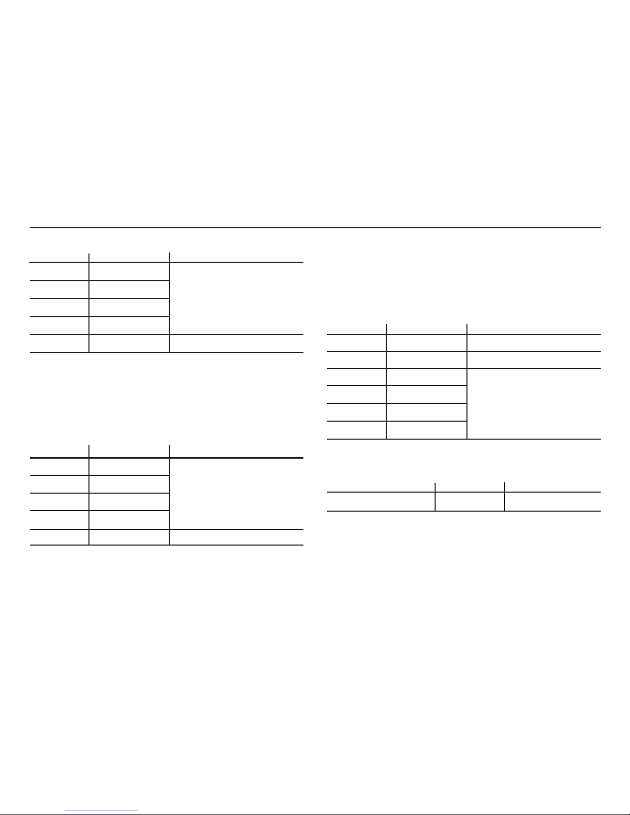
DC Current (Auto-ranging)
Range Resolution Accuracy
400.0 µA 0.1 µA
4000 µA 1 µA
40.00 mA 10 µA
300.0 mA 100 µA
10 A 10 mA ±2.5% of rdg ±3 digits
Overload Protection: 0.5 A/1000 V and 10 A/1000 V fuse.
Maximum Input: 4000 µA DC on µA range
400 mA DC on mA range
10 A DC on 10 A range
AC Current (Auto-ranging)
Range Resolution Accuracy
400.0 µA 0.1 µA
4000 µA 1 µA
40.00 mA 10 µA
300.0 mA 100 µA
10 A 10 mA ±3.0% of rdg ±5 digits
Overload Protection: 0.5 A/1000 V and 10 A/1000 V fuse.
AC Response: 50 Hz to 400 Hz
Maximum Input: 4000 µA AC rms on µA
400 mA AC rms on mA
10 A AC rms on 10 A range.
Resistance [Ω] (Auto-ranging)
Range Resolution Accuracy
400.0 Ω 0.1 Ω ±0.8% of rdg ±5 digits
4.000 kΩ 1 Ω ±0.8% of rdg ±2 digits
40.00 kΩ 10 Ω
400.0 kΩ 100 Ω
4.000 MΩ 1 kΩ
40.00 MΩ 10 kΩ
Input Protection: 1000 V DC or 1000 V AC rms.
AVO300: Diode Test
Test current Resolution Accuracy
0.3 mA typical/Open <1.5 V 1 mV ±10% of rdg ±5 digits
Open circuit voltage: 1.5 V DC typical
Overload protection: 1000 V DC or 1000 V AC rms.
9
±1.0% of rdg ±3 digits
±1.5% of rdg ±5 digits
±3% of rdg ±8 digits
Page 10
10
WARNING: To avoid electric shock, disconnect the test leads from any
source of voltage before removing the battery door.
1. When the batteries become exhausted or drop below the operating
voltage, the battery warning symbol will appear in the LCD display. The
battery should be replaced.
2. Follow instructions for installing battery. See the battery installation
section of this manual.
3. Dispose of the old battery properly.
WARNING: To avoid electric shock, do not operate your meter with the
battery cover removed.
BATTERY INSTALLATION
WARNING: To avoid electric shock, disconnect the test leads from any
source of voltage before removing the battery cover.
Do not operate the instrument with the battery cover removed
1. Disconnect the test leads from the meter.
2. Open the battery cover by loosening the screw using a cross head
screwdriver.
3. Insert the battery into battery holder, observing the correct polarity.
4. Put the battery cover back in place. Secure with the two screws.
NOTE: If your meter does not work properly, check the fuses and battery to
make sure that they are still good and that they are properly inserted.
AVO310: Diode Test
Test current Resolution Accuracy
1 mA typical/Open MAX.3 V 1 mV ±10% of rdg ±5 digits
Open circuit voltage: MAX. 3 V DC
Overload protection: 1000 V DC or 1000 V AC rms.
Audible continuity
Audible threshold: AVO300: Less than 10 Ω to 30 Ω
Test current: MAX. 0.3 mA
AVO310: Less than 35 Ω Test current MAX. 1.5 mA
Overload protection: 1000 V DC or 1000 V AC rms.
BATTERY AND FUSE REPLACEMENT
Page 11

11
ACCESSORIES
REPLACING THE FUSES
WARNING: To avoid electric shock, disconnect the test leads from any
source of voltage before removing the fuse/battery cover.
1. Disconnect the test leads from the meter and any item under test.
2. Open the fuse door by loosening the screw on the door using a cross
head screwdriver.
3. Remove the old fuse from its holder by gently pulling it out.
4. Install the new fuse into the holder.
5. Always use a fuse of the proper size and value (0.5 A/1000 V fast blow for
the 400 mA range, 10 A/1000 V fast blow for the 10 A range).
6. Put the fuse door back in place. Insert the screw and tighten it securely.
WARNING: To avoid electric shock, do not operate your meter until the
fuse door is in place and fastened securely.
Included accessories
Standard Red/Black lead set with test probes
Optional Accessories
Standard lead set with test probes and croc clips 6220-779
Fused lead set with test probes and croc clips 6220-789
Page 12

12
REPAIR AND WARRANTY
The instrument contains static sensitive devices, and care must be taken in
handling the printed circuit board. If an instrument’s protection has been
impaired it should not be used, but sent for repair by suitably trained and
qualified personnel. The protection is likely to be impaired if for example; it
shows visible damage; fails to perform the intended measurements; has
been subjected to prolonged storage under unfavourable conditions, or has
been subjected to severe transport stresses.
NEW INSTRUMENTS ARE GUARANTEED FOR 3 YEARS FROM THE
DATE OF PURCHASE BY THE USER.
Note: Any unauthorized prior repair or adjustment will automatically
invalidate the Warranty.
INSTRUMENT REPAIR AND SPARE PARTS
For service requirements for Megger Instruments contact:
Megger Limited or Megger
Archcliffe Road Valley Forge Corporate Centre
Dover 2621 Van Buren Avenue
Kent CT17 9EN Norristown PA 19403
England. U.S.A.
Tel: +44 (0) 1304 502 243 Tel: +1 610 676 8579
Fax: +44 (0) 1304 207 342 Fax: +1 610 676 8625
or an approved repair company.
Returning and Instrument for Repair
If it is necessary to retun an instrument for repair, a returns Authorisation
number must first be obtained by contacting one of the addresses shown.
You will be asked to provide key information, such as the instrument serial
number and fault reported when the number is issued. This will enable the
Service Department to prepare in advance for the receipt of your
instrument, and to provide the best possible service to you.
The Returns Authorisation number should be clearly marked on the outside
of the product packaging, and on any related correspondence. The
instrument should be sent, freight paid to the appropriate address. If
appropriate a copies of the original purchase invoice and of the packing
note, should be sent simultaneously by airmail to expedite clearance
through customs.
For instruments requiring repair outside the warranty period a repair
estimate will be submitted to the sender, if required, before work on the
instrument commences.
Approved Repair Companies
A number of independent instrument repair companies have been
authorised for repair work on most Megger instruments, using genuine
Megger spare parts. A list of approved companies is available from the UK
address shown on this page. Spare parts are also available.
Page 13

13
M
Multimètres numériques Série AVO300
MANUAL DE L’UTILISATEUR
Page 14

14
GCONSIGNES DE SÉCURITÉ
Les informations ci-après relatives à la sécurité doivent être respectées pour assurer aux personnes une sécurité maximale pendant le fonctionnement de cet
appareil de mesure.
■ N’utilisez pas l’appareil dans des environnements humides
■ N’essayez pas de réaliser des mesures au-delà de la plage maximale sélectionnée.
■ Une précaution toute particulière doit être apportée lorsque vous effectuez des mesures au-dessus de 50 V., notamment sur des barres conductrices de
courant sous tension.
■ Pour mesure la tension, l’instrument ne doit pas être commuté sur une gamme de courant ou de résistance, ou sur la position de contrôle de diode ou
de testeur de continuité.
■ Les circuits doivent impérativement être mis hors tension et isolés avant d’effectuer des essais de résistance.
■ Le sélecteur rotatif ne doit être tourné qu’après le retrait des connexions de test.
■ Toutes les tensions externes doivent être déconnectées de l'instrument avant le retrait de la pile.
■ Les cordons de test et les contacts doivent être en bon état, propres , et l’isolant ne doit pas être brisé ou fissuré.
■ Les autorités britanniques responsables de la sécurité recommandent d’utiliser des connexions de test à fusible lors de la mesure de la tension sur des
systèmes haute énergie.
■ Des fusibles de remplacement doivent avoir le type et les caractéristiques appropriés.
■ L’instrument ne doit pas être utilisé si l’une de ces parties, quelle qu’elle soit, est endommagée.
■ Vérifiez le bon fonctionnement de l’appareil en testant une tension connue avant et après l’utilisation. Ne pas l’utiliser si vous obtenez des résultats
erronés.
■ Il faut impérativement lire et comprendre tous les avertissements et les précautions avant d'utiliser un instrument. Ces avertissements et précautions
doivent être observés pendant le fonctionnement de cet instrument.
La législation en vigueur sur la sécurité et la santé impose aux utilisateurs de ces équipements d’effectuer une évaluation des risques sur tous les travaux
électriques, afin d’identifier les sources potentielles de danger et les risques d’accidents tels que les court-circuits. Si cette évaluation révèle un niveau de
risque significatif, l’utilisation de câbles de test protégés par fusibles peut être nécessaire.
NOTA
CET APPAREIL NE DOIT ÊTRE UTILISÉ QUE PAR DES PERSONES COMPÉTENTES ET SPÉCIALEMENT FORMÉES
Page 15

15
SOMMAIRE
INTRODUCTION 16
SYMBOLES ET INDICATEURS D’ALARME 16
FONCTIONNEMENT 16
Bouton MODE 16
Bouton GEL 16
Bouton RÉTROÉCLAIRAGE (uniquement AVO310) 17
Bouton MAX/MIN (uniquement AVO310) 17
MESURES DE TENSION DE CC 17
MESURES DE TENSION DE CA 17
MESURE DE COURANT CA 17
MESURE DE LA RÉSISTANCE [ Ω ]18
CONTRÔLE DE CONTINUITÉ 18
TEST DE DIODE 18
CARACTÉRISTIQUES 19
Remplacement de la PILE et du FUSIBLE 22
MISE EN PLACE DE LA PILE 22
REMPLACEMENT DES FUSIBLES 22
ACCESSORIES 23
RÉPARATIONS ET GARANTIE 24
Symboles utilisés sur l’appareil:
F
Attention : Risque de choc électrique
G Attention : Consulter les notes d’accompagnement
t
Equipement entièrement protégé par une double
isolation (Classe II)
c Equipement conforme aux directives européennes
applicables
Conformité « C-Tick »
N13117
Page 16
Merci d’avoir acheté l’un des multimètres numériques Megger de la série
AVO300.
Pour votre propre sécurité et afin de tirer le meilleur parti de votre
instrument, assurez-vous que vous avez lu et compris les avertissements et
les instructions ci-après relatives à la sécurité avant d'essayer d'utiliser
l'instrument.
Ce guide de l’utilisateur décrit le fonctionnement et les fonctions de la série
AVO300 des multimètres numériques indiquée ci-après.
AVO300
AVO310
SYMBOLES ET INDICATEURS D’ALARME
Continuité
BAT Pile faible
Test de diode
GEL Gel de données
AUTO Sélection automatique de gamme
CA Courant ou tension alternatif (ve)
CC Courant ou tension continu (e)
MAX/MIN Stocke la mesure la plus élevée ou la plus basse
Rétroéclairage
V Volts
A, mA, uA Plage de courant
Pour mettre en marche l’instrument, faites passer le sélecteur de plage de la
position ÉTEINTE sur n'importe quelle plage de mesure.
REMARQUE : Pour que votre pile dure plus longtemps, mettez
TOUJOURS le sélecteur de fonctions sur la position ÉTEINTE lorsque vous
n’utilisez pas l'appareil de mesure. Ces appareils de mesure ont une
fonction ARRÊT automatique qui ÉTEINT automatiquement l'appareil de
mesure si vous le laissez allumé. AVO300 :15 minutes, AVO310 : 30 minutes.
REMARQUE: Sur certaines plages de tension CA et CC faibles, avec les
cordons de test non raccordées à un appareil, l'écran peut afficher un relevé
changeant et aléatoire. Cela est normal et tient à la sensibilité d’entrée
élevée. Le relevé se stabilisera et l’appareil de mesure effectuera un relevé
approprié lorsqu’il sera relié à un circuit.
Bouton MODE
Ce bouton sert à sélectionner une mesure CA ou CC lorsque vous êtes dans
les plages ampères, milliampère et microampère.
Bouton GEL
La fonction GEL permet à l’appareil de mesure de « figer » une mesure pour
la consulter ultérieurement.
1. Appuyez sur le bouton GEL pour « figer » le relevé sur l’indicateur. Le
message « GEL » s’affichera.
2. Appuyez une nouvelle fois sur le bouton GEL pour revenir au
fonctionnement normal.
16
INTRODUCTION FONCTIONNEMENT
Page 17

17
Bouton RÉTROÉCLAIRAGE (uniquement AVO310)
1. Appuyez sur le bouton RÉTROÉCLAIRAGE pour allumer le voyant de
l'affichage.
2. Appuyez à nouveau sur le bouton RÉTROÉCLAIRAGE pour sortir du
mode éclairage.
Bouton MAX/MIN (uniquement AVO310)
La fonction MAX/MIN permet à l'appareil de mesure de saisir la mesure la
plus élevée ou la plus basse pour les consulter ultérieurement.
1. Appuyez sur le bouton MAX/MIN pour commencer la mesure. Le voyant
"MAX" ou "MIN" s’affichera.
2. Si les messages « MAX MIN » clignotent, l’instrument es dans le mode
MAX/MIN mais n’est pas en train d'enregistrer, appuyez sur le bouton
MAX/MIN pour sélectionner un mode.
3. Pour revenir au mode de mesure normal AUTO, maintenez enfoncé le
bouton MAX/MIN pendant 2 secondes.
MESURES DE TENSION CC
1. Réglez le sélecteur de fonction sur la position V CC (« mV » s’affiche).
2. Insérez la fiche banane du cordon de test noir dans le connecteur (COM)
négatif et la fiche banane du cordon de test rouge dans le connecteur (V)
positif.
3. Mettez en contact les pointes de la sonde d’essai sur le circuit testé.
Assurez-vous que vous respectez bien la bonne polarité (cordon rouge
sur positif, cordon noir sur négatif).
4. Lisez la tension sur l’afficheur. L’afficheur indiquera le point décimal et la
valeur appropriés. Si la polarité est inversée, l’écran affichera un signe
moins (-) devant la valeur.
MESURES DE TENSION CA
1. Réglez le sélecteur de fonction sur la position V CA.
2. Insérez la fiche banane du cordon de test noir dans le connecteur (COM)
négatif et la fiche banane du cordon de test rouge dans le connecteur (V)
positif.
3. Mettez en contact les pointes de la sonde d’essai sur le circuit testé.
4. Lisez la tension sur l’afficheur. L’afficheur indiquera le point décimal, la
valeur et le symbole appropriés (CA, V, etc.).
MESURE DE COURANT CC
ATTENTION: Ne faites pas de mesures de courant sur l’échelle 10A
pendant plus de 30 secondes. Toute mesure au-delà de 30 secondes peut
endommager l'appareil de mesure et/ou les cordons de test.
1. Insérez la fiche banane du cordon de test noir dans le connecteur (COM)
négatif.
2. Pour des mesures de courant allant jusqu’à 4000 µA CC, réglez le
sélecteur de fonction sur la position µA et insérez la fiche banane du
cordon de test rouge dans le connecteur (µA).
3. Pour des mesures de courant allant jusqu’à 400 mA CC, réglez le sélecteur
de fonction sur la gamme µA et insérez la fiche banane du cordon de test
rouge dans le connecteur (mA).
4. Pour des mesures de courant allant jusqu’à 10 A CC, réglez le sélecteur de
fonction sur la position A et insérez la fiche banane du cordon de test
rouge dans le connecteur 10 A.
5. Appuyez sur le bouton CA/CC jusqu’à l’affichage de l’indication "CC".
6. Mettez le circuit testé hors tension, puis ouvrez le circuit à l’endroit où
vous souhaitez mesurer le courant.
Page 18

18
7. Raccordez la sonde d’essai noire sur le côté négatif du circuit. Raccordez
la sonde d’essai rouge sur le côté positif du circuit.
8. Mettez le circuit sous tension.
9. Lisez le courant sur l’afficheur. L’afficheur indiquera le point décimal, la
valeur et le symbole appropriés.
10. Mettez le circuit hors tension avant de débrancher les cordons de test.
MESURE DE COURANT CA
ATTENTION: Ne faites pas de mesures de courant sur l’échelle 10A
pendant plus de 30 secondes. Toute mesure au-delà de 30 secondes peut
endommager l'appareil de mesure et/ou les cordons de test.
1. Insérez la fiche banane du cordon de test noir dans la prise (COM)
négative.
2. Pour des mesures de courant allant jusqu’à 10 A , réglez le sélecteur de
fonction sur la position A et insérez la prise du cordon de test rouge dans
le connecteur (10 A).
3. Pour des mesures de courant allant jusqu’à 400 mA , réglez le sélecteur de
fonction sur la gamme mA et insérez la fiche banane du cordon de test
rouge dans le connecteur (mA).
4. Pour des mesures de courant allant jusqu’à 10 A CA, réglez le sélecteur de
fonction sur la position A et insérez la fiche banane du cordon de test
rouge dans le connecteur 10 A.
5. Appuyez le bouton MODE. Il est possible de faire passer le mode de
mesure du CA au CC, selon les besoins.
6. Mettez le circuit testé hors tension, puis ouvrez le circuit à l’endroit où
vous souhaitez mesurer le courant.
7. Raccordez la sonde d’essai noire sur le côté négatif du circuit. Raccordez
la sonde d’essai rouge sur le côté positif du circuit.
8. Mettez le circuit sous tension. Lisez le courant sur l’afficheur. L’afficheur
indiquera le point décimal, la valeur et le symbole appropriés.
9. Mettez le circuit hors tension avant de débrancher les cordons de test.
MESURE DE LA RÉSISTANCE [ Ω ]
AVERTISSEMENT: Pour éviter le choc électrique, débranchez l’alimentation
vers l’unité testée et déchargez tous les condensateurs avant de relever
n’importe quelles mesures de la résistance. Enlevez les piles et débranchez
les cordons d'alimentation.
1. Réglez le sélecteur de fonction sur la position Ω.
2. Insérez la fiche du cordon de test noir dans la prise (COM) négative et la
fiche du cordon de test rouge dans le connecteur (Ω) positif.
3. Mettez en contact les pointes de la sonde d’essai d’un côté à l’autre du
circuit ou avec la partie testé (e). Il vaut mieux débranchez un côté de la
partie testée afin que le reste du circuit ne gêne pas la lecture de la
résistance.
4. Relevez la résistance sur l’afficheur. L’afficheur indiquera le point décimal,
la valeur et le symbole appropriés.
CONTRÔLE DE CONTINUITÉ
AVERTISSEMENT: Pour éviter le choc électrique, ne mesurez jamais la
continuité sur des circuits ou des câbles sous tension.
1. Réglez le sélecteur de gamme sur la position Ω.
2. Insérez la fiche du cordon de test noir dans la prise (COM) et la fiche du
cordon de test rouge dans la prise positive.
Page 19

19
CARACTÉRISTIQUES
3. Mettez en contact les pointes de la sonde d'essai sur le circuit ou le câble
que vous voulez contrôler.
4. Si la résistance est inférieure à 30 Ω, un signal sonore se fera entendre.
L’écran affichera également la résistance réelle en ohms.
TEST DE DIODE
AVERTISSEMENT: Pour éviter le choc électrique, ne testez aucune diode
sous tension.
1. Réglez le sélecteur de fonction sur la position .
2. Insérez la fiche du cordon de test noir dans la prise COM et la fiche du
cordon de test rouge dans la prise .
3. Mettez en contact les pointes de la sonde d'essai sur la diode ou à la
jonction du semi-conducteur que vous voulez tester. Notez le relevé de
l’appareil de mesure.
4. Inversez la polarité de la sonde en commutant la position de la
sonde. Notez ce relevé.
5. La diode ou la jonction peut être évaluée de la manière suivante :
A. Si un relevé indique une valeur et l’autre relevé affiche OL
(surcharge), la diode est bonne.
B. Si les deux relevés affichent OL, le dispositif est ouvert.
C. Si les deux relevés indiquent des valeurs très faibles ou sont égaux à zéro,
le dispositif est raccourci.
REMARQUE: La valeur indiquée sur l’afficheur pendant le contrôle de la
diode est la tension directe
Isolation: Classe 2, Double isolation
Catégorie de surtension (AVO300/310)
600 V CATIII ou 1000 V CATII
Affichage
AVO300: afficheur LCD 4000 comptages, 25,4 mm
de hauteur
AVO310: afficheur LCD 4000 comptages, 20mm de
hauteur
Rétroéclairage: Uniquement AVO310
Polarité: Indication automatique de polarité
négative (-)
Dépassement de gamme: Indication de signe « OL » (surcharge)
Indication de pile faible : un symbole de pile s’affiche lorsque la
tension de la pile descend sous le niveau de fonctionnement
Cadence de mesure : 2 fois par seconde nominale
Mise hors tension automatique
AVO300: l'appareil de mesure s’éteint automatiquement environ 15
minutes après une période d'inactivité
AVO310: l'appareil de mesure s’éteint automatiquement environ 30
minutes après une période d'inactivité
Milieu de fonctionnement : -10ºC à 50ºC (14ºF à 122ºF) avec une
humidité relative inférieure à 70%
Storage temperature: -30ºC à 60ºC (-4ºF à 140ºF) avec une
humidité relative inférieure à 80%
Page 20

20
Humidité relative : 90% (0ºC à 30ºC); 75% (30ºC à 40ºC);
45% (40ºC à 50ºC)
Pour une utilisation en intérieur, Hauteur maximale:
Fonctionnement: 3000 m
Stockage: 10,000 m
Degré de pollution: 2
Sécurité
Cet instrument est conforme aux normes : IEC/EN 61010-1 et
IEC 61010-031
Puissance: Une pile de 9 V, NEDA 1604, IEC 6F22
Dimensions: 182 (H) x 82 (W) x 55 (D) mm
Poids: Approx. 375g.
EMC
IEC 61326-1
Incertitudes opérationnelles: visite www.megger.com
Précision
La précision est donnée de 18ºC à 28ºC (65ºF à 83ºF), pour une humidité
relative inférieure à 70%
Tension CC (calibrage automatique)
Gamme Résolution Précision
400.0 mV 0.1 mV ±0.5% sur le relevé ±2 chiffres
4.000 V 1 mV
40.00 V 10 mV ±0,8% sur le relevé ±2 chiffres
400.0 V 100 mV
1000 V 1 V ±1% sur le relevé ±2 chiffres
Impédance d’entrée: 7.8 MΩ.
Entrée maximale: 1000 V cc
Tension CA (calibrage automatique)
Gamme Résolution Précision
400.0 mV
(uniquement AV0310) 0.1 mV
4.000 V 1 mV ±1% sur le relevé ±5 chiffres
40.00 V 10 mV
400.0 V 100 mV
1000 V 1 V ±1.5% sur le relevé ±5 chiffres
400 mV (uniquement AVO310)
Impédance d’entrée : 7.8 MΩ.
Réponse CA : 50Hz 60Hz
Page 21

21
Entrée maximale : 600 V ca. rms.
Courant CC (calibrage automatique)
Gamme Résolution Précision
400.0 µA 0.1 µA
4000 µA 1 µA
40.00 mA 10 µA
300.0 mA 100 µA
10 A 10 mA ±2.5% sur le relevé ±3 chiffres
Protection contre la surcharge: fusible 0.5 A/1000 V et 10 A/1000 V
Entrée maximale : 1000 µA cc sur gamme µA
400 mA cc sur gamme mA
10 A cc sur gamme 10 A
Courant CA (calibrage automatique)
Gamme Résolution Précision
400.0 µA 0.1 µA
4000 µA 1 µA
40.00 mA 10 µA
300.0 mA 100 µA
10 A 10 mA ±3.0% sur le relevé ±5 chiffres
Protection contre la surcharge : fusible 0.5 A/1000 V and 10 A/1000 V
Réponse c.a: 50 Hz à 400 Hz
Entrée maximale: 1000 µA ca rms sur µA
400 mA ca rms sur mA
10 A ca sur gamme 10 A
Résistance [Ω] (calibrage automatique)
Gamme Résolution Précision
400.0 Ω 0.1 Ω ±0.8% sur le relevé ±5 chiffres
4.000 kΩ 1 Ω ±0.8% sur le relevé ±2 chiffres
40.00 kΩ 10 Ω
400.0 kΩ 100 Ω
4.000 MΩ 1 kΩ
40.00 MΩ 10 kΩ
Protection d’entrée: 1000 V cc ou 1000 V ca rms
AVO300: test de diode
Gamme Résolution Précision
0.3 mA Type/Ouver <1.5 V 1 mV ±10% sur le relevé
±5 chiffres
Tension de circuit ouvert: 1.5 V cc type
Protection contre la surcharge: 1000 V cc ou 1000 V ca rms
±1.0 % sur le relevé ±3 chiffres
±1.5% sur le relevé ±5 chiffres
±3% sur le relevé ±8 chiffres
Page 22

22
REMPLACEMENT DE LA PILE ET DU FUSIBLE
AVO310 : test de diode
Courant d'essai Résolution Précision
1 mA type/Ouvert MAX. 3 V 1 mV ±10% sur le relevé
±5 chiffres
Tension de circuit ouvert: 3 V cc MAX
Protection contre la surcharge: 1000 V cc ou 1000 V ca rms
Continuité audible
Seuil audible: AVO300: moins de 10 Ω à 30 Ω
Courant d’essai: 0.3 mA MAX.
AVO310: moins de 35 Ω
Test current: 1.5 mA MAX.
Protection contre la surcharge: 1000 V cc ou 600 V ca rms
AVERTISSEMENT : Pour éviter le choc électrique, déconnectez les cordons
de mesure de toute source de tension avant d’enlever la porte de la pile.
1. Lorsque les piles sont déchargées ou que leur tension descend en
dessous de la tension de service, le symbole d’alarme de la pile s'affichera
à l’écran. La pile doit être remplacée.
2. Suivez les instructions pour l’installation d’une pile. Voir le chapitre sur
l’installation de la pile de ce manuel.
3. Mettez l’ancienne pile au rebut comme il convient.
AVERTISSEMENT : Pour éviter le choc électrique, ne faites pas fonctionner
votre appareil de mesure alors que le couvercle de la pile est enlevé.
MISE EN PLACE DE LA PILE
AVERTISSEMENT : Pour éviter le choc électrique, déconnectez les cordons
de mesure de toute source de tension avant de retirer le couvercle de la
pile.
Ne faites pas fonctionner votre appareil de mesure alors que le couvercle de
la pile est enlevé.
1. Débranchez les cordons de mesure de l’appareil de mesure.
2. Ouvrez le couvercle de la pile en desserrant la vis à l’aide d’un tournevis à
pointe cruciforme.
3. Insérez la pile dans le support de pile, en observant la bonne polarité.
4. Remettez le couvercle de la pile à sa place. Fixez-le à l’aide des deux
vis.
Page 23

23
ACCESSORIES
REMARQUE : Si votre appareil de mesure ne fonctionne pas normalement,
vérifiez les fusibles et la pile pour vous assurer qu'ils sont encore bons et
qu’ils ont été introduits convenablement.
REMPLACEMENT DES FUSIBLES
AVERTISSEMENT : Pour éviter le choc électrique, déconnectez les cordons
de mesure de toute source de tension avant de retirer les fusibles/le
couvercle de la pile.
1. Débranchez les cordons de mesure de l’appareil de mesure et tout
élément testé.
2. Ouvrez la porte du fusible en desserrant la vis qui se trouve sur la porte à
l’aide d’un tournevis à pointe cruciforme.
3. Retirez l’ancien fusible de son porte-fusible en le faisant sortir doucement
de son emplacement.
4. Installez le nouveau fusible dans le porte-fusible.
5. Utilisez toujours un fusible de la taille et de la valeur qui conviennent (0,5
A/1000 V à action rapide pour la gamme de 400 mA, 10 A/1000 V à action
rapide pour la gamme de 10 A).
6. Remettez la porte de fusible à sa place. Insérez la vis et serrez-là à fond.
AVERTISSEMENT : Pour éviter le choc électrique, ne faites fonctionner
votre appareil de mesure que lorsque la porte de fusible est en place et
fixée fermement.
Accessoires fournis
Jeu de cordon rouge/noir standard avec des sondes d’essai.
Accessoires en option
Jeu de cordon standard avec sondes d’essai et pinces
crocodiles 6220-779
Jeu de cordon à fusible avec sondes d’essai et pinces
crocodiles 6220-789
Page 24

24
RÉPARATIONS ET GARANTIE
Cet appareil comporte des pièces statiques fragiles. Manipuler avec soin la
carte à circuits imprimés. Ne pas utiliser l’appareil si sa protection est
endommagée mais faire réparer l’appareil par des personnes qualifiées et
spécialement formées à ce propos. La protection est endommagée, si, par
exemple, elle comporte des dommages visibles, si l’appareil ne peut
effectuer les mesures prévues, si l’appareil a longtemps été stocké dans de
mauvaises conditions ou s’il a été soumis à des chocs pendant le transport.
LES APPAREILS NEUFS SONT GARANTIS 3 ANS A
COMPTER DE LEUR DATE D’ACHAT
Nota: La garantie ne s’applique pas en cas de réparation ou d’ajustement
non autorisés.
RÉPARATION ET PIÈCES DE RECHANGE
Pour toute assistance concernant les appareils Megger contacter:
Megger Limited or Megger
Archcliffe Road 23 Rue Eugène Henaff
Dover 78190 TRAPPES
Kent CT17 9EN France
England.
Tel: +44 (0) 1304 502 243 Tel: +33 (0) 130160890
Fax: +44 (0) 1304 207 342 Fax: +33 (0) 134612377
ou toute autre société de réparation agréée.
Renvoi D’un Instrument Pour le faire Réparer
Si l’appareil doit être retourné pour réparation, l’utilisateur doit obtenir un
numéro d’autorisation de renvoi auprès de l’une des adresses mentionnées
ci-contre. Des informations telles que le numéro de série de l’appareil et le
défaut constaté devront être fournies. Ces informations permettront au
service clientèle de préparer la réception de votre appareil et de vous
apporter le meilleur service possible.
Le numéro d’autorisation de renvoi doit être clairement indiqué sur
l’emballage de l’appareil et mentionné lors de toute correspondance. Le
transport de l’appareil doit être prépayé jusqu’à l’adresse appropriée. Si
besoin, une copie de la facture et de la liste de colisage doivent être
envoyées simultanément par la poste pour le dédouanement.
Pour les appareils dont la réparation n’est pas couverte par la garantie, une
estimation du coût de réparation sera alors envoyée à l’expéditeur avant le
commencement des travaux.
Sociétés de réparation agréées
Plusieurs sociétés indépendantes ont été autorisées à effectuer des
réparations sur la plupart des appareils Megger. Elles utilisent les pièces de
rechange Megger d’origine. La liste de ces sociétés agréées est disponible à
l’adresse de Megger au Royaume Uni indiquée ci-contre. Ces sociétés
fournissent également les pièces de rechange.
Page 25

26
Page 26

27
M
Digitale Multimeter der AVO300-Serie
BEDIENUNGSANLEITUNG
Page 27

28
GSICHERHEITSHINWEISE
Um eine maximale persönliche Sicherheit während des Betriebs dieses Messgeräts zu gewährleisten, müssen die folgenden Sicherheitshinweise beachtet
werden:
■ Nicht in feuchten Umgebungen verwenden.
■ Es dürfen keine Messungen außerhalb des maximalen Wählbereichs versucht werden.
■ Bei Messungen oberhalb von 50 V muss insbesondere an stromführenden Sammelschienen äußerste Vorsicht angewendet werden.
■ Zur Spannungsmessung darf das Gerät nicht auf einen Stromstärke- oder Widerstandsmessbereich oder auf die Diodenprüfungs- oder Summerposition
eingestellt sein.
■ Stromkreise müssen aberregt und isoliert werden, bevor Widerstandsprüfungen ausgeführt werden.
■ Der Drehwählschalter darf nur nach dem Entfernen der Testanschlüsse betätigt werden.
■ Alle externen Spannungen müssen von dem Gerät abgetrennt werden, bevor die Batterie entfernt wird.
■ Prüfkabel und Messspitzen müssen sich in gutem Zustand befinden, sauber sein und dürfen keine defekte oder gerissene Isolierung aufweisen.
■ Die britischen Sicherheitsbehörden empfehlen bei der Spannungsmessung von Hochenergiesystemen die Verwendung mit Sicherungen versehener
Prüfkabel.
■ Ersatzsicherungen müssen den richtigen Typ und die richtigen Nennwerte haben.
■ Das Instrument darf nicht verwendet werden, wenn Teile des Instruments beschädigt sind.
■ Überprüfen Sie den korrekten Betrieb des Geräts durch Prüfen einer bekannten Spannung vor und nach dem Gebrauch. Das Gerät darf nicht verwendet
werden, wenn widersprüchliche Ergebnisse erhalten werden.
■ Die Sicherheitswarnhinweise und Vorsichtsmaßnahmen müssen vor dem Gebrauch eines Instruments durchgelesen und verstanden worden sein. Sie
müssen während des Betriebs dieses Geräts befolgt werden.
Die Benutzer dieser Geräte und/oder ihre Arbeitgeber sollten nicht vergessen, dass die Gesetzgebung über Gesundheit und Sicherheit die Durchführung
von gültigen Risikobewertungen aller elektrischer Arbeiten verlangt, um potenzielle Quellen elektrischer Gefahren und das Risiko elektrischer Verletzungen,
z.B. infolge unbeabsichtigter Kurzschlüsse, zu identifizieren.
Falls die Bewertung zeigt, dass das Risiko erheblich ist, dann ist der Gebrauch von gesicherten Prüfkabeln angebracht.
HINWEIS
DAS GERÄT DARF NUR VON ENTSPRECHEND AUSGEBILDETEN UND FACHKUNDIGEN PERSONEN BENUTZT WERDEN
Page 28

29
INHALT
EINFÜHRUNG 30
SYMBOLE UND MELDUNGEN 30
BETRIEB 30
MODUS-Wahltaste 30
HALTEN-Taste 30
HINTERGRUNDBELEUCHTUNGS-Taste (nur AVO310) 31
MAX/MIN-Taste (nur AVO310) 31
GS-SPANNUNGSMESSUNG 31
WS-SPANNUNGSMESSUNG 31
GS-STROMSTÄRKEMESSUNG 31
WS-STROMSTÄRKEMESSUNG 31
WIDERSTANDSMESSUNG [ Ω ]32
DURCHGANGSPRÜFUNG 32
DIODENPRÜFUNG 33
SPEZIFKATION 34
Austausch von BATTERIE und SICHERUNG 37
BATTERIEINSTALLATION 37
AUSTAUSCH DER SICHERUNGEN 37
ACCESSORIES 38
REPARATUR UND GARANTIE 39
Auf dem Gerät wurden folgende Symbole verwendet:
F Achtung: Gefahr eines elektischen Schlags
G Achtung: siehe beiliegende Hinweise
t Geräte durch doppelte Isolation geschützt
(Klasse II)
c Das Gerät entspricht den aktuellen EU-Richtlinien.
Das Gerät entspricht den ‘C tick’ Anforderungen
N13117
Page 29

30
EINFÜHRUNG BETRIEB
Wir danken Ihnen für den Kauf eines digitalen Multimeters der Serie
AVO300 von Megger.
Bitte achten Sie zur Ihrer eigenen Sicherheit und um Ihr Gerät maximal
nutzen zu können darauf, dass Sie die folgenden Sicherheitshinweise und
die Bedienungsanleitung gelesen und verstanden haben, bevor Sie das
Gerät benutzen.
Diese Bedienungsanleitung beschreibt den Betrieb und die Funktionen der
folgenden AVO300-Serien digitaler Multimeter:
AVO300
AVO310
SYMBOLE UND MELDUNGEN
Durchgang
BAT Niedriger Batterieladezustand
Diodenprüfung
HOLD Daten halten
AUTO Automatische Bereichswahl
AC Alternating Wechselstrom oder -spannung
DC Gleichstrom oder -spannung
MAX/MIN Speichert die höchste oder niedrigste Messung
Hintergrundbeleuchtung
V Volts
A, mA, uA Strommessbereich
Zum Einschalten des Geräts drehen Sie den Bereichsschalter aus der
ausgeschalteten Position auf einen beliebigen Messbereich.
HINWEIS: Für eine maximale Batterielebensdauer schalten Sie den
Funktionsschalter IMMER auf die ausgeschaltete Position, wenn das Gerät
nicht benutzt wird. Diese Messgeräte sind mit einer automatischen
Abschaltung ausgestattet, die das Messgerät nach einer bestimmten
Zeitspanne ausschalten, wenn es versehentlich eingeschaltet bleibt.
AVO300:15 Minuten, AVO310: 30 Minuten.
HINWEIS: Bei einigen niedrigen WS- und GS-Bereichen kann das Display
einen zufälligen, sich ändernden Messwert anzeigen, wenn die Prüfkabel
nicht an ein zu messendes Gerät angeschlossen sind. Dies ist normal und
auf die hohe Eingangsempfindlichkeit zurückzuführen. Der Messwert
stabilisiert sich und Sie erhalten eine korrekte Messung, wenn das Gerät an
einen Stromkreis angeschlossen wird.
MODUS-Wahltaste
Zur Auswahl von WS- oder GS-Messungen in den Ampere-, mA- oder uABereichen.
HALTEN-Taste
Die Funktion HALTEN erlaubt dem Messgerät, eine Messung zur späteren
Bezugnahme „einzufrieren".
1. Drücken Sie die HALTEN-Taste, um den Messwert auf der Anzeige
„einzufrieren". Die Meldung „HOLD" (HALTEN) erscheint auf dem
Display.
2. Drücken Sie die HALTEN-Taste erneut, um zum normalen Betrieb
zurückzukehren.
Page 30

31
HINTERGRUNDBELEUCHTUNGS-Taste (nur AVO310)
1. Drücken Sie die Taste HINTERGRUNDBELEUCHTUNG, um die DisplayBeleuchtung einzuschalten.
2. Drücken Sie die Taste HINTERGRUNDBELEUCHTUNG erneut, um den
Beleuchtungsmodus zu verlassen.
MAX/MIN-Taste (nur AVO310)
Die MAX/MIN-Funktion erlaubt dem Messgerät, die höchste oder niedrigste
Messung zur späteren Bezugnahme zu erfassen.
1. Drücken Sie die MAX/MIN-Taste, um mit der Messung zu beginnen. Die
Meldung „MAX" oder „MIN" erscheint auf dem Display.
2. Wenn die „MAX MIN" Meldungen blinken, befindet sich das Instrument
im MAX/MIN-Modus, zeichnet jedoch keine Werte auf. Drücken Sie die
MAX/MIN-Taste, um einen Modus auszuwählen.
3. Um zum normalen AUTO-Messmodus zurückzukehren, halten Sie die
MAX/MIN-Taste 2 Sekunden lang gedrückt.
GS-SPANNUNGSMESSUNG
1. Stellen Sie den Funktionsschalter auf die V GS-Position (es erscheint „mV"
auf dem Display).
2. Stecken Sie den schwarzen Bananenstecker des Prüfkabels in die negative
(COM) Buchse und den roten Bananenstecker des Prüfkabels in die
positive (V) Buchse.
3. Berühren Sie den zu prüfenden Stromkreis mit den Prüfsondenspitzen.
Achten Sie auf die korrekte Polarität (rotes Kabel in positiver Buchse,
schwarzes Kabel in negativer Buchse).
4. Lesen Sie den Spannungswert auf dem Display ab. Das Display zeigt den
richtigen Dezimalpunkt und den richtigen Wert an. Wenn die Polarität
umgekehrt ist, zeigt das Display ein (-) Minuszeichen vor dem Wert an.
WS-SPANNUNGSMESSUNG
1. Stellen Sie den Funktionsschalter auf die V WS-Position.
2. Stecken Sie den schwarzen Bananenstecker des Prüfkabels in die negative
(COM) Buchse und den roten Bananenstecker des Prüfkabels in die
positive (V) Buchse.
3. Berühren Sie den zu prüfenden Stromkreis mit den Prüfsondenspitzen.
4. Lesen Sie den Spannungswert auf dem Display ab. Das Display zeigt den
richtigen Dezimalpunkt, Wert und das zugehörige Symbol (AC, V) an.
GS-STROMSTÄRKEMESSUNG
VORSICHT: Führen Sie im 10 A-Bereich keine Stromstärkemessungen über
mehr als 30 Sekunden durch. Eine längere Messung als 30 Sekunden kann
zu Schäden am Messgerät und/oder den Prüfkabeln führen.
1. Stecken Sie den schwarzen Bananenstecker des Prüfkabels in die negative
(COM) Buchse.
2. Stellen Sie den Funktionsschalter für Stromstärkemessungen bis zu
4000 µA GS auf die uA-Position und stecken Sie den roten
Bananenstecker des Prüfkabels in die (µA) Buchse.
3. Stellen Sie den Funktionsschalter für Stromstärkemessungen bis zu
400 mA GS auf den mA-Bereich und stecken Sie den roten
Bananenstecker des Prüfkabels in die (mA) Buchse.
4. Stellen Sie den Funktionsschalter für Stromstärkemessungen bis zu
10 A GS auf die A-Position und stecken Sie den roten Bananenstecker
des Prüfkabels in die 10 A-Buchse.
5. Drücken Sie die WS/GS-Taste, bis auf dem Display „GS" erscheint.
6. Trennen Sie den zu prüfenden Schaltkreis von der Stromversorgung und
Page 31

32
öffnen Sie den Schaltkreis dann an der Stelle, an der Sie die Stromstärke
messen möchten.
7. Schließen Sie die schwarze Prüfsonde an der negativen Seite des
Schaltkreises an. Schließen Sie die rote Prüfsonde an der positiven Seite
des Schaltkreises an.
8. Setzen Sie den Schaltkreis unter Strom.
9. Lesen Sie die Stromstärke auf dem Display ab. Das Display zeigt den
richtigen Dezimalpunkt, Wert und das entsprechende Symbol an.
10. Trennen Sie den Schaltkreis von der Stromversorgung, bevor Sie die
Prüfkabel ausstecken.
WS-STROMSTÄRKEMESSUNG
VORSICHT: Führen Sie im 10 A-Bereich keine Stromstärkemessungen über
mehr als 30 Sekunden durch. Eine längere Messung als 30 Sekunden kann
zu Schäden am Messgerät und/oder den Prüfkabeln führen.
1. Stecken Sie den schwarzen Bananenstecker des Prüfkabels in die negative
(COM) Buchse.
2. Stellen Sie den Funktionsschalter für Stromstärkemessungen bis zu
10 A auf die A-Position und stecken Sie den roten Bananenstecker des
Prüfkabels in die 10 A-Buchse.
3. Stellen Sie den Funktionsschalter für Stromstärkemessungen bis zu
400 mA auf den mA-Bereich und stecken Sie den roten Bananenstecker
des Prüfkabels in die (mA) Buchse.
4. Stellen Sie den Funktionsschalter für Stromstärkemessungen bis zu
10 A WS auf die A-Position und stecken Sie den roten Bananenstecker des
Prüfkabels in die 10 A-Buchse.
5. Drücken Sie die MODUS-Taste. Der Messmodus schaltet sich wie
gewünscht auf WS oder GS um.
6. Trennen Sie den zu prüfenden Schaltkreis von der Stromversorgung und
öffnen Sie den Schaltkreis dann an der Stelle, an der Sie die Stromstärke
messen möchten.
7. Schließen Sie die schwarze Prüfsonde an der negativen Seite des
Schaltkreises an. Schließen Sie die rote Prüfsonde an der positiven Seite
des Schaltkreises an.
8. Setzen Sie den Schaltkreis unter Strom. Lesen Sie die Stromstärke auf
dem Display ab. Das Display zeigt den richtigen Dezimalpunkt, Wert und
das entsprechende Symbol an.
9. Trennen Sie den Schaltkreis von der Stromversorgung, bevor Sie die
Prüfkabel ausstecken.
WIDERSTANDSMESSUNG [ Ω ]
WARNHINWEIS: Zur Vermeidung elektrischer Schläge trennen Sie den zu
prüfenden Schaltkreis von der Stromversorgung ab und entladen Sie allen
Kondensatoren, bevor Sie eine Widerstandsmessung vornehmen. Entfernen
Sie die Batterien und stecken Sie die Netzkabel aus.
1. Stellen Sie den Funktionsschalter auf die Position Ω.
2. Stecken Sie den schwarzen Bananenstecker des Prüfkabels in die negative
(COM) Buchse und den roten Bananenstecker des Prüfkabels in die
positive Ω-Buchse.
3. Berühren Sie den zu prüfenden Stromkreis oder das zu prüfende Teil mit
den Prüfsondenspitzen. Es ist am besten, eine Seite des zu prüfenden
Teiles abzutrennen, damit der restliche Stromkreis die
Widerstandsmessung nicht beeinflusst.
4. Lesen Sie den Widerstand auf dem Display ab. Das Display zeigt den
richtigen Dezimalpunkt, Wert und das entsprechende Symbol an.
Page 32

33
DURCHGANGSPRÜFUNG
WARNHINWEIS: Zur Vermeidung von elektrischen Schlägen dürfen Sie
den Durchgang niemals an unter Spannung stehenden Stromkreisen oder
Leitern messen.
1. Stellen Sie den Bereichsschalter auf die Position Ω.
2. Stecken Sie den schwarzen Bananenstecker des Prüfkabels in die (COM)
Buchse und den roten Bananenstecker des Prüfkabels in die positive
Buchse.
3. Berühren Sie den Stromkreis oder den Leiter, den Sie prüfen möchten,
mit den Prüfsondenspitzen.
4. Wenn der Widerstand weniger als 30 Ω beträgt, ertönt ein akustisches
Signal. Das Display zeigt außerdem den tatsächlichen Widerstand in Ohm
an.
DIODENPRÜFUNG
WARNHINWEIS: Zur Vermeidung elektrischer Schläge dürfen Sie niemals
eine unter Spannung stehende Diode prüfen.
1. Stellen Sie den Funktionsschalter auf die Position .
2. Stecken Sie den schwarzen Bananenstecker des Prüfkabels in die (COM)
Buchse und den roten Bananenstecker des Prüfkabels in die positive
Buchse.
3. Berühren Sie die Diode oder Halbleiterverbindung, die Sie prüfen
möchten, mit den Prüfsondenspitzen. Notieren Sie den Messwert.
4. Kehren Sie die Sondenpolarität durch Wechsel der Sondenposition
um. Notieren Sie auch diesen Messwert.
5. Die Diode oder Verbindung kann wie folgt bewertet werden:
A. Wenn ein Messwert einen Wert und der andere Messwert OL anzeigt, ist
die Diode in gutem Zustand.
B. Wenn beide Messwerte OL anzeigen, ist das Gerät offen.
C. Wenn beide Messwerte sehr klein oder gleich Null sind, ist das Gerät
kurzgeschlossen.
HINWEIS: Der auf dem Display während der Diodenprüfung angezeigte
Wert ist die Durchlassspannung.
Page 33

34
SPEZIFIKATION
Isolierung: Klasse 2, doppelt isoliert.
Überspannungskategorie:
(AVO300/310) 600 V KATIII oder 1000 V KATII
Display
AVO300: 4000 Zähler-LCD-Anzeige, Höhe 25,4 mm
AVO310: 4000 Zähler-LCD-Anzeige, Höhe 20 mm
Hintergrundbeleuchtung: nur AVO310
Polarität: Automatische, (-) negative Polaritätsanzeige
Oberhalb des Messbereichs: OL-Meldung
Anzeige für niedrige
Batterieleistung: Es wird ein Batteriesymbol angezeigt,
wenn die Batteriespannung unter den
Betriebswert fällt.
Messrate: Nennwert 2 pro Sekunde
Automatische Abschaltung
AVO300: Gerät schaltet sich nach einer Inaktivität
von ungefähr 15 Minuten automatisch aus
AVO310: Gerät schaltet sich nach einer Inaktivität
von ungefähr 30 Minuten automatisch aus
Betriebsumgebung: -10ºC bis 50ºC bei <70% relativer
Luftfeuchtigkeit.
Storage temperature: -30ºC bis 60ºC bei <80% relativer
Luftfeuchtigkeit.
Relative Luftfeuchtigkeit: 90% (0ºC bis 30ºC); 75% (30ºC bis 40ºC);
45% (40ºC bis 50ºC).
Zum Gebrauch in Innenräumen, maximale Höhe:
Betrieb: 3000 m
Lagerung: 10,000 m
Verschmutzungsgrad: 2
Sicherheit
Das Gerät erfüllt die folgenden Normen: IEC61010-1 und
IEC61010-031
Stromversorgung: Eine 9 V-Batterie, NEDA 1604, IEC 6F22
Abmessungen: 182 (H) x 82 (W) x 55 (D) mm
Gewicht: Approx.: 375g.
EMC
IEC61326-1
Betriebliche Unklarheiten: Besuch www.megger.com
Page 34

Genauigkeit
Das Gerät misst bei 18ºC bis 28ºC und weniger als 70% relative
Luftfeuchtigkeit genau
GS-Spannung (Automatische Messbereichsumschaltung)
Bereich Auflösung Genauigkeit
400.0 mV 0.1 mV ±0,5% des Messwerts ±2 Stellen
4.000 V 1 mV
40.00 V 10 mV ±0,8% des Messwerts ±2 Stellen
400.0 V 100 mV
1000 V 1 V ±1% des Messwerts ±2 Stellen
Eingangsimpedanz: 7.8 MΩ.
Maximale Eingangsspannung: 1000 V dc
WS-Spannung (Automatische Messbereichsumschaltung)
Bereich Auflösung Genauigkeit
400.0 mV
(nur AV0310) 0.1 mV
4.000 V 1 mV ±1% des Messwerts ±5 Stellen
40.00 V 10 mV
400.0 V 100 mV
1000 V 1 V ±1,5% des Messwerts ±5 Stellen
400 mV (nur AVO310)
Eingangsimpedanz: 7.8 MΩ.
WS-Frequenzbereich: 50Hz 60Hz
Maximale Eingangsspannung: 1000 V WS Effektivspannung.
GS-Stromstärke (Automatische Messbereichsumschaltung
Bereich Auflösung Genauigkeit
400.0 µA 0.1 µA
4000 µA 1 µA
40.00 mA 10 µA
300.0 mA 100 µA
10 A 10 mA ±2.5% of rdg ±3 digits
Überlastschutz: 0,5 A/1000 V- und 10 A/1000 V-Sicherung.
Maximale Eingangsstromstärke: 1000 µA GS im µA-Bereich
400 mA GS im mA-Bereich
10 A GS im 10 A-Bereich
WS-Stromstärke (Automatische Messbereichsumschaltung)
Bereich Auflösung Genauigkeit
400.0 µA 0.1 µA
4000 µA 1 µA
40.00 mA 10 µA
300.0 mA 100 µA
10 A 10 mA ±3,0% des Messwerts ±5 Stellen
Überlastschutz: 0,5 A/1000 V- und 10 A/1000 V-Sicherung
WS-Frequenzbereich: 50 Hz bis 400 Hz
±1.0% of rdg ±3 digits
±1,5% des Messwerts ±5
Stellen
35
Page 35

36
Maximale Eingangsstromstärke: 400 µA WS Effektivstrom bei µA
400 mA WS Effektivstrom bei mA
10 A WS Effektivstrom im 10 A-Bereich
Widerstand [Ω] (Automatische Messbereichsumschaltung)
Bereich Auflösung Genauigkeit
400.0 Ω 0.1 Ω ±0,8% des Messwerts ±5 Stellen
4.000 kΩ 1 Ω
40.00 kΩ 10 Ω
400.0 kΩ 100 Ω
4.000 MΩ 1 kΩ
40.00 MΩ 10 kΩ
Eingangsschutz: 1000 V GS oder 600 V WS Effektivspannung.
AVO300: Diodenprüfung
Prüfstromstärke Auflösung Genauigkeit
0,3mA typisch/offen <1,5 V 1 mV ±10% des Messwerts
±5 Stellen
Spannung bei offenem Stromkreis: 1.5 V GS typisch
Überlastschutz: 1000 V GS oder 600 V WS Effektivspannung
AVO310: Diodenprüfung
Prüfstromstärke Auflösung Genauigkeit
1 mA typisch/offen MAX. 3 V 1 mV ±10% des Messwerts
±5 Stellen
Spannung bei offenem Stromkreis: MAX. 3 V GS
Überlastschutz: 1000 V GS oder 1000 V WS Effektivspannung
Hörbarer Durchgang
Hörbarkeitsschwelle: AVO300: Unter 10 Ω bis 30 Ω
Prüfstromstärke: MAX. 0.3 mA
AVO310: Unter 35 Ω Prüfstromstärke MAX. 1,5 mA
Überlastschutz: 1000 V GS oder 1000 V WS Effektivspannung
±0.8% of rdg ±2 digits
±3% des Messwerts ±8 Stellen
Page 36

37
AUSTAUSCH VON BATTERIE UND SICHERUNG
WARNHINWEIS: Zur Vermeidung elektrischer Schläge müssen die
Prüfkabel von allen Spannungsquellen abgetrennt werden, bevor die
Batterieklappe abgenommen wird.
1. Wenn der Batterieladezustand stark absinkt oder unter die
Betriebsspannung fällt, erscheint das Batteriewarnsymbol auf der LCDAnzeige. Die Batterie muss ausgetauscht werden.
2. Befolgen Sie die Anweisungen zum Einsetzen neuer Batterien. Siehe
Abschnitt zur Batterieinstallation in dieser Bedienungsanleitung.
3. Entsorgen Sie alte Batterien ordnungsgemäß.
WARNHINWEIS: Zur Vermeidung elektrischer Schläge dürfen Sie Ihr
Messgerät nicht bei abgenommener Batterieklappe betreiben.
BATTERIEINSTALLATION
WARNHINWEIS : Zur Vermeidung elektrischer Schläge müssen die
Prüfkabel von allen Spannungsquellen abgetrennt werden, bevor die
Batterieklappe abgenommen wird.
Betreiben Sie das Gerät nicht bei abgenommener Batterieklappe.
1. Trennen Sie die Prüfkabel vom Messgerät ab.
2. Öffnen Sie die Batterieklappe durch Lösen der Schraube mit Hilfe eines
Schraubendrehers.
3. Legen Sie die Batterie unter Beachtung der korrekten Polarität in die
Batteriehalterung ein.
4. Setzen Sie die Batterieklappe wieder ein. Befestigen Sie sie mit den
beiden Schrauben.
HINWEIS: Wenn Ihr Gerät nicht korrekt funktioniert, prüfen Sie die
Sicherungen und die Batterie, um sicherzustellen, dass sie sich in gutem
Zustand befinden und richtig eingelegt sind.
AUSTAUSCH DER SICHERUNGEN
WARNHINWEIS: Zur Vermeidung elektrischer Schläge müssen die
Prüfkabel von allen Spannungsquellen abgetrennt werden, bevor die
Sicherungs-/Batterieklappe abgenommen wird.
1. Trennen Sie die Prüfkabel vom Messgerät und dem zu prüfenden
Stromkreis ab.
2. Öffnen Sie die Sicherungsklappe durch Lösen der Schraube an der Klappe
mit Hilfe eines Kreuzschraubendrehers.
3. Entfernen Sie die alte Sicherung aus ihrer Halterung, indem Sie sie
vorsichtig herausziehen.
4. Setzen Sie die neue Sicherung in die Halterung ein.
5. Verwenden Sie immer eine Sicherung mit der richtigen Größe und den
richtigen Nennwerten (flinke Sicherung mit 0,5 A/1000 V für den
400 mA-Bereich, flinke Sicherung mit 10 A/1000 V für den 10 A-Bereich).
6. Setzen Sie die Sicherungsklappe wieder ein. Setzen Sie die Schraube ein
und ziehen Sie sie an.
WARNHINWEIS: Zur Vermeidung elektrischer Schläge dürfen Sie Ihr
Messgerät nur bei eingesetzter und festgeschraubter Sicherungsklappe
betreiben.
Page 37

38
ZUBEHÖR
Mitgeliefertes Zubehör
Standardset mit rotem/schwarzem Kabel mit Prüfsonden
Optionales Zubehör
Standardkabelset mit Prüfsonden und
Krokodilklemmen 6220-779
Mit Sicherung ausgestattetes Kabelset mit Prüfsonden
und Krokodilklemmen 6220-789
Page 38

39
REPARATUR UND GARANTIE
Das Gerät enthält auf statische Ladung empfindliche Komponenten und die
Leiterplatte muss vorsichtig gehandhabt werden. Wenn der Schutz eines
Gerätes beeinträchtigt wurde, sollte es nicht benutzt werden und zur
Reparatur durch entsprechend ausgebildetes und qualifiziertes Personal
eingesandt werden. Der Schutz kann dann beeinträchtigt sein, wenn das
Gerät beispielsweise sichtbar beschädigt ist, die vorgesehenen Messungen
nicht ausführt, unter ungünstigen Bedingungen über längere Zeit gelagert
wurde oder extremen Transportbeanspruchungen ausgesetzt war.
NEUE GERÄTE HABEN EINE 3-JÄHRIGE GARANTIE AB DEM
KAUFDATUM.
Hinweis: Durch jede vorherige unberechtigte Reparatur oder Veränderung
erlischt die Garantie automatisch.
GERÄTEREPARATUR UND ERSATZTEILE
Für Service-Ansprüche der Megger Geräte kontaktieren Sie bitte:
Megger Limited oder Megger
Archcliffe Road Valley Forge Corporate Centre
Dover 2621 Van Buren Avenue
Kent CT17 9EN Norristown PA 19403
England. U.S.A.
Tel: +44 (0) 1304 502 243 Tel: +1 610 676 8579
Fax: +44 (0) 1304 207 342 Fax: +1 610 676 8625
oder einen anerkannten Reparaturbetrieb.
Einschicken eines Geräts zur Reparatur
Wenn Sie ein Gerät zur Reparatur an den Hersteller einschicken wollen,
müssen Sie zuerst eine Autorisierungsnummer erhalten, indem Sie sich an
eine der genannten Anschriften wenden. Sie werden bei der Ausstellung der
Nummer gebeten werden, wichtige Informationen wie die
Geräteseriennummer und den berichteten Mangel anzugeben. Dies hilft der
Kundendienstabteilung, sich im Voraus auf den Erhalt Ihres Geräts
vorzubereiten und Ihnen den bestmöglichen Service zu bieten.
Die Rücksendeautorisierungsnummer muss auf der Außenseite der
Produktverpackung und auf jeder zugehörigen Korrespondenz deutlich
angegeben werden. Das Gerät muss mit vorausbezahlter Fracht an die
entsprechende Anschrift eingeschickt werden. Gleichzeitig sind eine Kopie
der Originalrechnung und des Lieferscheins per Luftpost einzuschicken, um
die Zollabfertigung zu beschleunigen.
Für Geräte, bei denen nach Ablauf der Garantiezeit eine Reparatur
erforderlich wird, schicken wir dem Einsender auf Wunsch einen
Kostenvoranschlag zu, bevor wir mit der Arbeit an dem Gerät beginnen.
Autorisierte Reparaturbetriebe
Eine Reihe unabhängiger Gerätereparaturbetriebe wurden für die Reparatur
der meisten Megger-Geräte autorisiert und verwenden dafür OriginalMegger-Ersatzteile. Eine Liste anerkannter Reparaturbetriebe ist von unserer
Büro im Vereinigten Königreich zu erhalten (Siehe Addresse auf dieser
Seite). Ersatzteile sind ebenfalls erhältlich.
Page 39

40
Page 40

41
M
Multímetros Digitales Serie AVO300
MANUAL DEL USUARIO
Page 41

42
GADVERTENCIAS DE SEGURIDAD
The following safety information must be observed to insure maximum personal safety during the operation at this meter:
■ No lo utilice en ambientes húmedos.
■ No se deben realizar medidas superiores al nivel máximo seleccionado.
■ Se debe poner sumo cuidado cuando se realicen mediciones superiores a 50 V, especialmente en barras ómnibus móviles.
■ Para medir el voltaje, el instrumento no debe estar enchufado a ninguna escala de corriente o resistencia, o al control de diodos o al puesto del zumbador.
■ Los circuitos deben estar desconectados y aislados antes de llevar a cabo pruebas de resistencia.
■ El interruptor seleccionador rotatorio sólo debe activarse después de desactivar las conexiones de prueba.
■ Todos los voltajes externos deben desconectarse del instrumento antes de sacar la batería.
■ Los cables y contactos de prueba deben estar en buenas condiciones, limpios, y su aislamiento no puede estar roto o agrietado.
■ Las Autoridades de Seguridad del Reino Unido recomiendan el uso de cables de prueba fundidos cuando se mida el voltaje en sistemas de elevada
energía.
■ Los fusibles de recambio deben ser del tipo y de la clase correctos.
■ El instrumento no debe utilizarse si alguna de sus partes está dañada.
■ Compruebe el correcto funcionamiento del instrumento haciendo una prueba en un voltaje conocido antes y después del uso. No lo utilice si se obtienen
resultados engañosos.
■ Antes de utilizar el instrumento, deben leerse y entenderse las advertencias y las precauciones. Deben respetarse durante el funcionamiento del mismo.
Se recuerda a los usuarios de estos equipos y/o sus empleados que la legislación nacional de Salud y Seguridad requiere la realización de evaluaciones de
riesgo válidas de todos los trabajos eléctricos para identificar fuentes potenciales de peligro eléctrico y riesgos de descargas eléctricas, como corto circuitos
involuntarios. Cuando las evaluaciones indican que el riesgo es significativo, entonces puede ser adecuado emplear conexiones de prueba con fusibles.
NOTA:
LOS INSTRUMENTOS SÓLO DEBEN SER UTILIZADOS POR PERSONAS COMPETENTES Y ADECUADAMENTE CAPACITADAS.
Page 42

43
CONTENIDO
INTRODUCCIÓN 44
SÍMBOLOS E INDICADORES 44
FUNCIONAMIENTO 44
Botón MODE 44
Botón HOLD 44
Botón BACKLIGHT (AVO310 sólo) 45
Botón MAX/MIN (AVO310 sólo) 45
MEDIDAS DE VOLTAJE DE DC 45
MEDIDAS DE VOLTAJE DE AC 45
MEDIDA DE CORRIENTE DE DC 45
MEDIDA DE CORRIENTE DE AC 46
MEDIDA DE RESISTENCIA [ Ω ]46
COMPROBACIÓN DE CONTINUIDAD 46
PRUEBA DE DIODO 47
ESPECIFICACIONES 47
BATERÍA y recambio de FUSIBLES 50
INSTALACIÓN DE LA BATERÍA 50
RECAMBIO DE FUSIBLES 51
ACCESORIOS 51
REPARACIÓN Y GARANTÍA 52
Símbolos empleados en el instrumento:
F Precaución: riesgo de sacudida eléctrica
G Precaución: refiérase a las notas adjuntas
t Equipo completamente protegido por doble
aislamiento (Clase II)
c El equipo cumple con las actuales directrices de la
UE.
El equipo cumple con los requerimientos ‘C tick’
N13117
Page 43

44
INTRODUCCIÓN FUNCIONAMIENTO
Gracias por comprar uno de los multímetros digitales de la serie AVO300 de
Megger.
Por su propia seguridad y con el fin de sacar el máximo provecho a este
instrumento, le rogamos que se asegure de leer y entender las siguientes
advertencias e instrucciones de seguridad antes de intentar utilizar el
instrumento.
Este manual de usuario describe el manejo y las funciones de los siguientes
multímetros digitales de la serie AVO300:
AVO300
AVO310
SÍMBOLOS E INDICADORES
Continuidad
BAT Batería baja
Prueba de diodo
HOLD Contención de datos
AUTO Calibración automática
AC Corriente o Voltaje Alternos
DC Corriente o Voltaje Continuos
MAX/MIN Almacena la medida más alta y la más baja
Luz trasera
V Voltios
A, mA, uA Nivel de corriente
Para encender el instrumento, gire el botón de la posición OFF a cualquier
escala de medida.
Nota: Para una mayor duración de la batería, coloque la función
interruptor SIEMPRE en la posición OFF cuando no se esté utilizando el
medidor. Estos medidores disponen de la función Auto OFF que apaga
automáticamente el medidor si se deja encendido. AVO300:15 minutos,
AVO310: 30 minutos.
Nota: En algunas escalas de bajo voltaje de AC (CA: corriente alterna) y DC
(CC: corriente continua), cuando los cables de prueba no están conectados
al dispositivo, es posible que la pantalla muestre una lectura aleatoria y
cambiante. Esto es normal y está provocado por la elevada entrada de
sensibilidad. La lectura se estabilizará y proporcionará una medida correcta
cuando se conecte al circuito.
Botón MODE
Para seleccionar la medida de AC o DC en amperios, escalas de mA o uA.
Botón HOLD
La función HOLD permite al medidor "congelar" una medida a la que
referirse más tarde.
1. Pulse el botón HOLD para "congelar" la lectura en el indicador. El mensaje
"HOLD" aparecerá en la pantalla.
2. Vuelva a pulsar el botón HOLD para volver a las operaciones normales.
Botón BACKLIGHT (LUZ TRASERA) (AVO310 sólo)
1. Pulse el botón BACKLIGHT para encender la luz de la pantalla.
2. Pulse de nuevo el botón BACKLIGHT para salir del modo luz.
Page 44

45
Botón MAX/MIN (AVO310 sólo)
El botón de función MAX/MIN permite al medidor capturar la medida más
alta o más baja para una referencia posterior.
1. Pulse el botón MAX/MIN para iniciar la medición. El indicador "MAX" o
"MIN" aparecerá en la pantalla.
2. Si los mensajes "MAX MIN" parpadean, el instrumento se encuentra en
modo MAX/MIN pero no está registrando ningún dato, pulse el botón
MAX/MIN para seleccionar un modo.
3. Para volver al modo de medición normal AUTO, mantenga el botón
MAX/MIN pulsado durante 2 segundos.
MEDIDAS DE VOLTAJE DE DC
1. Coloque la función interruptor en la posición V DC (aparecerá "mV" en la
pantalla).
2. Inserte el enchufe macho de cable de prueba negro en el enchufe
hembra (COM) negativo y el enchufe macho de cable de prueba rojo en
el enchufe hembra positivo (V).
3. Conecte las puntas de sonda de prueba al circuito en prueba. Asegúrese
de que tiene cuidado con la correcta polaridad (el cable rojo al positivo,
el cable negro al negativo).
4. Lea el voltaje en la pantalla. La pantalla indicará el punto decimal correcto
y el valor. Si la polaridad se invierte, la pantalla mostrará un menos (-)
delante del valor.
MEDIDAS DE VOLTAJE DE AC
1. Coloque la función interruptor en la posición V AC.
2. Inserte el enchufe macho de cable de prueba negro en el enchufe
hembra (COM) negativo y el enchufe macho de cable de prueba rojo en
el enchufe hembra positivo (V).
3. Conecte las puntas de sonda de prueba al circuito en prueba.
4. Lea el voltaje en la pantalla. La pantalla indicará el punto decimal
correcto, el valor y el símbolo (AC, V, etc.).
MEDIDA DE LA CORRIENTE DE DC
AVISO: No realice medidas de corriente en la escala 10 A durante más de
30 segundos. Si se excede de este tiempo, se podrían dañar el medidor y/o
los cables de prueba.
1. Inserte el enchufe macho de cable de prueba negro en el enchufe
hembra (COM) negativo.
2. Para medidas de corriente de hasta 4000 µA de DC, fije la función
interruptor en la posición uA e inserte el enchufe macho de cable de
prueba rojo en el enchufe hembra (uA).
3. Para medidas de corriente de hasta 400 mA de DC, coloque la función
interruptor en la escala mA e inserte el enchufe macho del cable de
prueba rojo en el enchufe hembra (mA).
4. Para medidas de corriente de hasta 10 A de DC, coloque la función
interruptor en la posición A e inserte el enchufe macho del cable de red
rojo en el enchufe hembra 10 A.
5. Pulse el botón AC/DC hasta que aparezca "DC" en la pantalla.
6. Desactive la electricidad del circuito en prueba, después abra el circuito
en el punto en que quiera medir la corriente.
7. Conecte la sonda de prueba negra a la parte negativa del circuito.
Conecta la sonda de prueba roja a la parte positiva del circuito.
8. Aplique la electricidad al circuito.
9. Lea la corriente en la pantalla. La pantalla indicará el punto decimal
Page 45

correcto, el valor y el símbolo.
10. Desconecte la electricidad del circuito antes de desconectar los cables
de prueba.
MEDIDA DE LA CORRIENTE DE AC
AVISO: No realice medidas de corriente en la escala 10 A durante más de
30 segundos. Si se excede de este tiempo, se podrían dañar el medidor y/o
los cables de prueba.
1. Inserte el enchufe de cable de prueba negro en el enchufe (COM)
negativo.
2. Para medidas de corriente de hasta 10 A, fije la función interruptor en la
posición A e inserte el enchufe de cable de prueba rojo en el enchufe
hembra (10 A).
3. Para medidas de corriente de hasta 400 mA, coloque la función
interruptor en la escala mA e inserte el enchufe macho del cable de
prueba rojo en el enchufe hembra (mA).
4. Para medidas de corriente de hasta 10 A de AC, coloque la función
interruptor en la posición A e inserte el enchufe macho del cable de red
rojo en el enchufe hembra 10 A.
5. Pulse el botón MODE. El modo de medida cambiará entre AC y DC según
se desee.
6. Desactive la electricidad del circuito en prueba, después abra el circuito
en el punto en que quiera medir la corriente.
7. Conecte la sonda de prueba negra a la parte negativa del circuito.
Conecta la sonda de prueba roja a la parte positiva del circuito.
8. Aplique la electricidad al circuito. Lea la corriente en la pantalla. La
pantalla indicará el punto decimal correcto, el valor y el símbolo.
9. Desconecte la electricidad del circuito antes de desconectar los cables de
prueba.
MEDIDA DE RESISTENCIA [Ω]
ADVERTENCIA: Para evitar descargas eléctricas, desconecte la electricidad
de la unidad a prueba y descargue todos los capacitadores antes de tomar
cualquier medida de resistencia. Saque la batería y desenchufe los cables de
la red eléctrica.
1. Fije la función interruptor en la posición Ω.
2. Inserte el enchufe del cable de prueba negro en el enchufe (COM)
negativo y el enchufe del cable de prueba rojo en el enchufe hembra
positivo Ω.
3. Conecte las puntas de sonda de prueba al circuito o a la parte a prueba.
Es mejor desconectar un lado de la parte a prueba para que el resto del
circuito no interfiera con la lectura de la resistencia.
4. Lea la resistencia en la pantalla. La pantalla indicará el punto decimal
correcto, el valor y el símbolo.
COMPROBACIÓN DE CONTINUIDAD
ADVERTENCIA : Para evitar descargas eléctricas, no mida nunca la
continuidad en los circuitos o los cables que tengan voltaje.
1. Fije el interruptor selector en la posición Ω .
2. Inserte el enchufe del cable negro en el enchufe COM y el enchufe del
cable rojo de prueba en el enchufe positivo.
3. Conecte las puntas de sonda de prueba al circuito o al cable que desea
comprobar.
4. Si la resistencia es inferior a 50 Ω, sonará la señal audible. La pantalla
también mostrará la resistencia real en ohmios.
46
Page 46

47
ESPECIFICACIONES
PRUEBA DE DIODO
ADVERTENCIA: Para evitar las descargas eléctricas, no haga pruebas
con ningún diodo que tenga voltaje.
1. Coloque la función interruptor en esta posición .
2. Inserte el enchufe del cable de prueba negro en el enchufe COM y el
enchufe del cable de prueba rojo en el enchufe .
3. Conecte las puntas de sonda de prueba al diodo o a la conexión
semiconductor con la que desee hacer pruebas. Anote la lectura del
medidor.
4. Invierta la polaridad de sonda conectando la posición de sonda. Anote
esta lectura.
5. El diodo o la conexión se pueden evaluar como sigue:
A. Si una lectura muestra un valor y la otra lectura muestra OL, el
diodo es válido.
B. Si ambas lecturas muestran OL, el dispositivo está abierto.
C. Si ambas lecturas son muy pequeñas o muestran cero, se ha producido
un cortocircuito en el dispositivo.
ADVERTENCIA : El valor indicado en la pantalla durante la comprobación
del diodo es el voltaje anterior.
Aislamiento: Clase 2, aislamiento doble
Categoría de sobretensión: (AVO300/310)
600V CATIII o 1000V CATII
Pantalla
AVO300: 4000 unidades de cuenta de pantalla LCD, 25,4mm de altura
AVO310: 4000 unidades de cuenta de pantalla LCD, 20mm de altura
Luz trasera: AVO310 solo
Polaridad: Automática, (-) indicación de polaridad
negativa
Intervalo suplementario: Indicación de marca "OL"
Indicación de batería baja: cuando el voltaje de la batería cae por
debajo del nivel operativo, se muestra un símbolo de batería.
Índice de medición: 2 veces por segundo nominal
Autoencendido apagado
AVO300: El medidor se apaga automáticamente después de
aproximadamente 15 minutos de inactividad.
AVO310: El medidor se apaga automáticamente después de
aproximadamente 30 minutos de inactividad.
Entorno operativo: -10ºC a 50ºC (14ºF a 122ºF) a <70% de
humedad relativa.
Storage temperature: -30ºC a 60ºC (-4ºF a 140ºF) a <80% de
humedad relativa.
Humedad relativa: 90% (0ºC a 30ºC); 75% (30ºC a 40ºC);
45% (40ºC a 50ºC)
Page 47

48
Altura máxima para uso interior:
Operativa:
3000 m
Almacenamiento: 10,000 m
Grado de polución: 2
Seguridad
El instrumento cumple con: IEC61010-1 y IEC61010-031
Electricidad: Una batería de 9V, NEDA 1604, IEC 6F22
Dimensiones: 182 (H) x 82 (W) x 55 (D) mm
Peso: Approx. 375g.
EMC
IEC61326-1
Inexactitudes operacionales: visita www.megger.com
Precisión
Se ofrece una precisión de 18ºC a 28ºC (de 65ºF a 83ºF), menos del
70% de HR
Voltaje de DC (Calibración automática)
Alcance Resolución Precisión
400.0 mV 0.1 mV ±0,5% de rdg ±2 dígitos
4.000 V 1 mV
40.00 V 10 mV ±0.8% de rdg ±2 dígitos
400.0 V 100 mV
1000 V 1 V ±1% de rdg ±2 dígitos
Impedancia de entrada: 7.8 MΩ.
Entrada máxima: 1000 V dc
Voltaje de AC (Calibración automática)
Alcance Resolución Precisión
400.0 mV
(AV0310 solo) 0.1 mV
4.000 V 1 mV ±1% de rdg ±5 dígitos
40.00 V 10 mV
400.0 V 100 mV
1000 V 1 V ±1.5% de rdg ±5 dígitos
400 mV (AVO310 solo)
Impedancia de entrada: 7.8 MΩ.
Page 48

49
Respuesta de la AC: 50Hz 60Hz
Entrada máxima: 600 V ac rms.
Corriente DC (Calibración automática)
Alcance Resolución Precisión
400.0 µA 0.1 µA
4000 µA 1 µA
40.00 mA 10 µA
300.0 mA 100 µA
10 A 10 mA ±2.5% de rdg ±3 dígitos
Protección de sobrecarga: 0.5 A/1000 V and 10 A/1000 V fusibles.
Entrada máxim: 1000 µA dc en un nivel µA
400 mA dc en un nivel mA
10 A dc en un nivel 10 A
AC (Calibración automática)
Alcance Resolución Precisión
400.0 µA 0.1 µA
4000 µA 1 µA
40.00 mA 10 µA
300.0 mA 100 µA
10 A 10 mA ±3.0% de rdg ±5 dígitos
Protección de sobrecarga: 0.5 A/1000 V and 10 A/1000 V fuseibles.
Respuesta de la AC: 50 Hz a 400 Hz
Entrada máxima: 1000 µA ac rms en µA
400 mA ac rms en mA
10A ac rms en un nivel de 10A.
Resistencia [Ω] (Calibración automática)
Alcance Resolución Precisión
400.0 Ω 0.1 Ω ±0.8% de rdg ±5 dígitos
4.000 kΩ 1 Ω ±0.8% de rdg ±2 dígitos
40.00 kΩ 10 Ω
400.0 kΩ 100 Ω
4.000 MΩ 1 kΩ
40.00 MΩ 10 kΩ
Protección de Entrada: 1000 V dc o 1000 V ac rms.
Prueba de Diodo
Corriente de prueba Resolución Precisión
0.3 mA typical/Open <1.5 V 1 mV ±10% de rdg
±5 dígitos
Voltaje de circuito abierto: 1,5 V dc típico
Protección de sobrecarga: 1000 V dc o 1000 V ac rms
±3% de rdg ±8 dígitos
±1.0% de rdg ±3 dígitos
±1.5% de rdg ±5 dígitos
Page 49

50
BATERÍA Y RECAMBIO DE FUSIBLES
AVO310: Prueba de Diodo
Corriente de prueba Resolución Precisión
1mA típico/Abierto MAX.3V 1 mV ±10% de rdg ±5 digitos
Voltaje de circuito abierto: MAX. 3 V dc
Protección de sobrecarga: 1000 V dc o 1000 V ac rms
Continuidad audible
Límite audible: AVO300: Inferior a 10 Ω hasta 30 Ω
Corriente de prueba: MAX. 0.3 mA
AVO310: Inferior a 35 Ω Corriente de prueba MAX. 1,5 mA
Protección de sobrecarga: 1000 V dc o 600 V ac rms.
ADVERTENCIA: Para evitar descargas eléctricas, desconecte los cables de
prueba de cualquier fuente de voltaje antes de retirar la puerta de la batería.
1. Cuando se agote la batería o se encuentre por debajo del voltaje
operativo, el símbolo de advertencia de batería aparecerá en la
pantalla LCD. Debe cambiarse la batería.
2. Siga las instrucciones de instalación de la batería. Ver la sección sobre
Instalación de la batería en este manual.
3. Deshágase de la antigua batería de forma adecuada.
ADVERTENCIA: Para evitar descargas eléctricas, no utilice el medidor
cuando se haya retirado la tapa de la batería.
INSTALACIÓN DE LA BATERÍA
ADVERTENCIA: Para evitar descargas eléctricas, desconecte los cables de
prueba de cualquier fuente de voltaje antes de retirar la tapa de la batería.
No utilice el instrumento cuando haya retirado la tapa de la batería.
1. Desconecte los cables de prueba del medidor.
2. Abra la tapa de la batería, dejando el tornillo suelto utilizando un
destornillador de estrella.
3. Inserte la batería en la funda de la batería, vigilando la correcta polaridad.
4. Vuelva a poner la tapa de la batería en su sitio. Asegúrela con los dos
tornillos.
NOTA: Si su medidor no funciona correctamente, compruebe los fusibles y
la batería para asegurarse de que aún se encuentran en buenas condiciones
y de que están insertados adecuadamente.
Page 50

51
ACCESSORIOS
RECAMBIO DE FUSIBLES
ADVERTENCIA: Para evitar descargas eléctricas, desconecte los cables de
prueba de cualquier fuente de voltaje antes de retirar los fusibles/ la tapa de
la batería.
1. Desconecte los cables de prueba del medidor y cualquier objeto en
prueba.
2. Abra la puerta de fusibles, dejando el tornillo de la puerta suelto
utilizando un destornillador estrella.
3. Saque el antiguo fusible de su funda retirándolo con suavidad.
4. Coloque el nuevo fusible en la funda.
5. Utilice siempre un fusible de tamaño y valor correctos (0,5 A/1000 V de
sopladura firme para el nivel 400 mA, 10 A/1000 V de sopladura firme para
el nivel 10 A).
6. Vuelva a colocar la puerta de fusibles en su sitio. Inserte el tornillo y
sujétela con seguridad.
ADVERTENCIA: Para evitar descargas eléctricas, no maneje el medidor
hasta que la puerta de fusibles esté en su sitio y esté sujeta con seguridad.
Accesorios incluidos
Conjunto de cables rojos/negros estándar con sondas de prueba
Accesorios opcionales
Conjunto de cables estándar con sondas de prueba
y pinzas cocodrilo 6220-779
Conjunto de cables fundidos con sondas de prueba
y pinzas cocodrilo 6220-789
Page 51

52
REPARACIÓN Y GARANTÍA
El instrumento contiene dispositivos sensibles estáticos y se debe tener
cuidado al manipular la tabla de circuito impresa. Si la protección de un
instrumento se ve afectada no debe utilizarse: envíelo para que sea reparado
por personal adecuadamente entrenado y calificado. Probablemente la
protección resulte dañada si por ejemplo: presenta daño visible; fracasa al
realizar las mediciones deseadas; ha permanecido almacenada durante un
período prolongado bajo condiciones desfavorables; o ha sido transportada
en malas condiciones.
LOS NUEVOS INSTRUMENTOS TIENEN GARANTÍA DE 3 AÑOS A
PARTIR DE LA FECHA DE COMPRA DEL USUARIO.
Nota: Toda reparación o ajuste previo no autorizado invalidará la Garantía
automáticamente.
REPARACIÓN DEL INSTRUMENTO Y REPUESTOS
Para requerimientos de servicio técnico para los instrumentos Megger
sírvase contactarse a:
Megger Limited or Megger
Archcliffe Road Valley Forge Corporate Centre
Dover 2621 Van Buren Avenue
Kent CT17 9EN Norristown PA 19403
England. U.S.A.
Tel: +44 (0) 1304 502 243 Tel: +1 610 676 8579
Fax: +44 (0) 1304 207 342 Fax: +1 610 676 8625
o bien a una empresa de reparaciones autorizada.
Devolución de un instrumento para reparación
Si es necesario devolver un instrumento para su reparación, primero deberá
obtener un número de autorización de devolución contactándose con una
de las direcciones suministradas. Al proporcionársele el número, se le
pedirá que provea información clave, como el número de serie del
instrumento y características del fallo. Esto permitirá que el Departamento
de Servicio se prepare con anticipación a la recepción del instrumento y le
brinde el mejor servicio posible.
El número de autorización de devolución debe indicarse claramente en la
parte exterior del envoltorio del producto y en toda la correspondencia
relacionada con el mismo. El instrumento debe enviarse con el flete pagado
a la dirección correspondiente. Si corresponde, simultáneamente deberá
enviar una copia de la factura y nota de empaque por correo aéreo para
agilizar los trámites ante la aduana.
Para aquellos instrumentos que requieran reparación fuera del período de
garantía, se enviará un estimado de reparación al remitente si lo solicita,
antes de comenzar el trabajo de reparación del instrumento.
Empresas de reparaciones autorizadas
Se ha autorizado a un grupo de empresas independientes de reparación de
instrumentos para realizar trabajos de reparación de la mayoría de los
instrumentos Megger, utilizando repuestos Megger legítimos. En la
dirección de Inglaterra suministrada en esta página podrá obtener una lista
de las empresas aprobadas. También hay repuestos disponibles.
Page 52

Page 53

M
Megger products are distributed in 146 countries worldwide.
The company reserves the right to change the specification or design without prior notice.
Megger is a registered trademark
Part No. AVO300_UG_V04 1108
www.megger.com
Megger Limited
Archcliffe Road, Dover
Kent CT17 9EN England
T +44 (0)1 304 502101
F +44 (0)1 304 207342
E uksales@megger.com
Megger
4271 Bronze Way, Dallas,
Texas 75237-1019 USA
T +1 800 723 2861 (USA ONLY)
T +1 214 333 3201
F +1 214 331 7399
E ussales@megger.com
Megger
Z.A. Du Buisson de la Couldre
23 rue Eugène Henaff
78190 TRAPPES France
T +33 (0)1 30.16.08.90
F +33 (0)1 34.61.23.77
E infos@megger.com
Megger Pty Limited
Unit 26 9 Hudson Avenue
Castle Hill
Sydney NSW 2125 Australia
T +61 (0)2 9659 2005
F +61 (0)2 9659 2201
E ausales@megger.com
Megger Limited
110 Milner Avenue Unit 1
Scarborough Ontario M1S 3R2
Canada
T +1 416 298 9688 (Canada only)
T +1 416 298 6770
F +1 416 298 0848
E casales@megger.com
 Loading...