

Page 1

Order OnLine
Motor and Phase Rotation Tester
■
Complete phase-sequence and motorrotation testing in one instrument
■
Ensures correct phase hookup in one
easy test
■
Rugged and portable tester
■
Performs additional polarity and
continuity checks
www.BiddleMegger.com
DESCRIPTION
The Motor and Phase Rotation Tester permits the electrical
contractor or industrial maintenance electrician to
permanently connect and tape the terminals of the motor
being installed, without having to first energize the motor
by a temporary hookup from a power source, if available,
to determine motor rotation. Therefore, the test set
eliminates the need for temporary connections that can be
time consuming, costly and quite hazardous, particularly
where many large, high-voltage motors are involved.
Also, certain types of drives should never be rotated in the
wrong direction. In such cases, the temporary hookup or
trial method, having a fifty-fifty chance of being wrong,
can do serious harm.
The three motor leads on the left side of the test set are
for attachment to the terminals of the motor being tested
for rotation determination.
Fuses are inserted in the motor A and C test leads as
protection in the event the user accidentally touches these
leads to an energized circuit. These standard fuses are
easily removed and replaced from their panel-mounted
holders.
The three lines leading to the right of the test set are for
direct attachment to energized ac power systems up to 600
volts to determine the system phase sequence.
A four-position switch selects the test to be made —
system phase sequence, motor rotation and transformer
polarity. The selector switch connects a D-size dry cell into
the circuit when the rotation of a motor or the polarity of
a transformer is being checked. In the OFF position, both
the meter and the battery are disconnected from all
circuits.
A push switch is connected in series with the battery and
opens the circuit during transformer polarity testing.
The dry cell is easily removed and replaced from its panelmounted holder by a coin-slot access cap.
The dc zero-center ammeter indicates correct or incorrect
rotation or polarity by deflecting its pointer to the right or
left. A zero or null adjuster is provided for the ammeter.
APPLICATIONS
The Motor and Phase Rotation Tester provides a positive
way toidentify the leads of a disconnected polyphase
motor; it also identifies true phase sequence of energized
60-Hertz ac power lines up to 600 volts. Both are
necessary to ensure that a motor will rotate in a prescribed
direction when energized.
There are three other important uses for this unique
testing device: it can determine the polarity of power and
instrument transformers; it can identify phase and polarity
of winding sections of multiple-winding (delta- and starconnected) motors; and it can be used as a continuity
tester in checking electrical circuits.
Page 2
Motor and Phase Rotation Tester
FEATURES AND BENEFITS
■
Determines rotation direction of one-, two- or threephase motors before connection to line
■
Determines phase rotation or sequence of energized
power circuits
■
Determines polarity of instrument and power
transformers
■
Determines phase/polarity of unmarked motor windings
■
Identifies true phase sequence of energized ac power
lines up to 600 volts (Higher voltages can be tested by
interposing a step-down transformer.)
SPECIFICATIONS
Input (specify one)
50/60 Hz or 25/50/60/400 Hz
Enclosure
The test set is enclosed in an ABS high-impact plastic case that
has a handle and hinged, removable lid. The deep lid provides
storage space for the instruction manual and test leads.
Dimensions
9 H x 7.5 W x 7.5 D in.
(23 H x 19 W x 19 W cm)
Weight
3.5 lb (1.6 kg)
Example Operation
Motor Connection for a 9-Wire, 3-Phase, Dual-Voltage,
Single-Speed, Delta Connection.
In the delta-connected winding, one terminal in each group is
common to two winding sections. This terminal can be identified
by using the motor rotation circuit as a bridge. Connect all three
MOTOR leads together. Set the selector switch to the MOTOR
position. Operate the ZERO ADJ. control to bring the meter
pointer to zero (center). Connect the three MOTOR leads to the
three terminals of the group in any order. Observe the meter
deflection. Reverse the A and B MOTOR leads. Again observe
the deflection. Reverse the B and C MOTOR leads. Note the
deflection. Return to the connection that gave the smallest
deflection of the meter. At this point, the B MOTOR lead is
connected to the common terminal. Now make a motor rotation
test with the leads connected as above ; rebalance the tester if
necessary, using the ZERO ADJ. control, and then turn the motor
slightly in the direction in which it is desired to run. If no
preferred direction is specified, turn it clockwise when viewed
from the drive end. If the deflection is in the INCORRECT
direction, reverse MOTOR leads A and C. When the CORRECT
deflection is obtained, the terminals in the group should be
marked according to the MOTOR lead markers. The number 1
should be used as a prefix to identify the group. Thus, the
terminal connected to the A MOTOR lead is marked 1A. The
common terminal is marked 1B, and the remaining terminal 1C.
Select a second group of leads. Determine the common terminal
and rotation in the same manner as described above. In tagging
these terminals, the prefix number is temporarily omitted. The
terminals are tagged A, B, C. If done properly, B will mark the
common lead. At this stage, the identification of terminals has
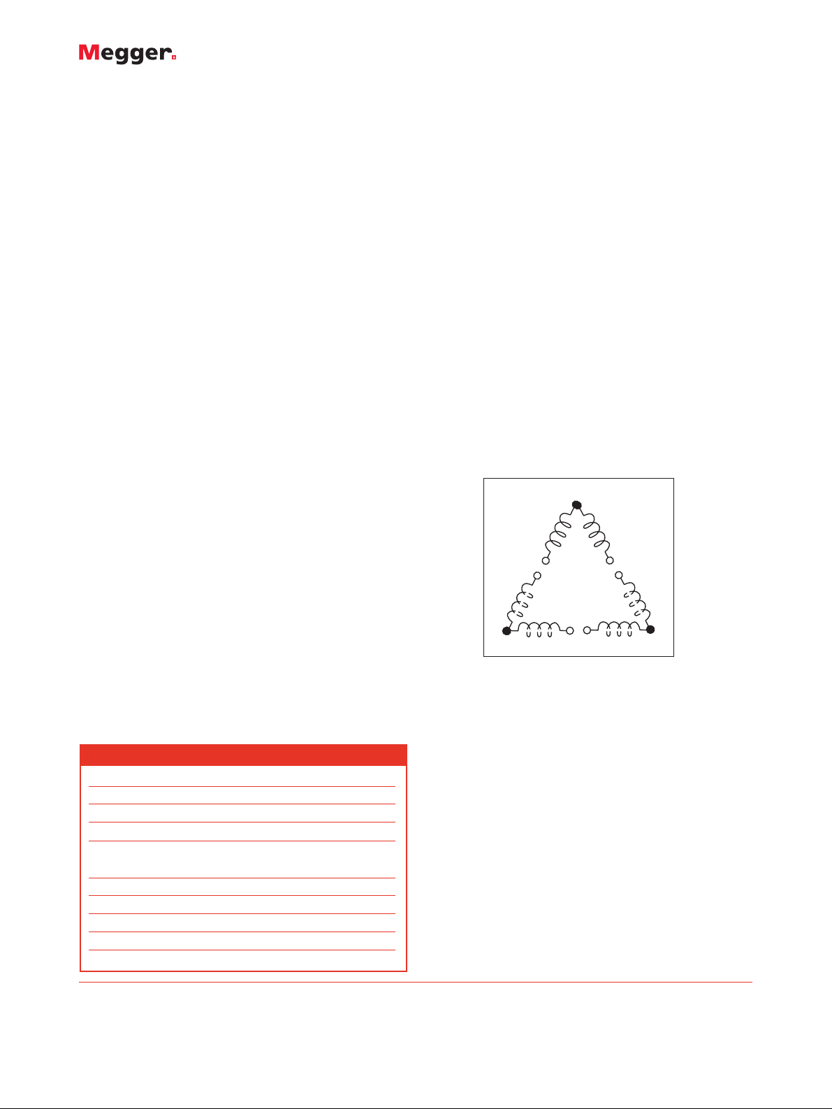
reached the point shown in the figure. It remains to be
determined whether this second group belongs in the 2 or 3
position. This can be determined by an induced voltage test that
indicates whether coil A-B or coil B-C is in phase with coil 1B-1C.
By continuing to apply similar steps, the entire configuration can
be determined. Similarly, appropriate modifications of the general
procedure can be employed to determine other types of winding
configurations.
First section identified in a 9-Wire, 3-Delta Motor
1B
1A
1C
C
A
B
B
A
C
Item (Qty) Cat. No.
Motor and Phase Rotation Tester
50/60 Hz 560060
25/50/60/400 Hz 560400
Included Accessories
Attached test leads
Line, 6 ft [1.8 m]
Motor, 4 ft [1.2 m]
Fuses, standard 250 V, 3 A
Instruction manual AVTM56-Jb
ORDERING INFORMATION
Registered to ISO 9001:2000 Reg no. Q 09290
Registered to ISO 14001 Reg no. EMS 61597
MeterCenter
2046 West Peninsula Circle
Chandler, AZ 85248 USA
Telephone: (480) 659-8351
Toll Free: (800) 230-6008
Fax: (480) 659-8361
Email: Sales@BiddleMegger.com
MOTOR_PHASE_TESTER_DS_en_V10
Megger is a registered trademark
 Loading...