

Page 1
M 210170
Insulation &
Low Resistance Tester
User Guide
SAFETY WARNINGS
✱ Safety Warnings and Precautions must be read and understood
before the instrument is used. They must be observed during use.
✱ The circuit under test must be switched off, de - energized and
isolated
before Insulation or Continuity tests are made.
✱ Circuit connections must not be touched during a test.
✱ The test button must not be pressed while connecting the test
leads or while changing ranges.
✱ The ‘Test’button must not be pressed when making a voltage test.
✱ The Default Voltmeter, and Automatic discharge are additional
safety features and
should not be regarded as a substitute for
normal safe working practice.
✱ The 210170 is protected for connection to Power distribution
systems up to 300 V
Line - Ground, and 500 V Line - Line for
Installation Category III*.
✱ It is recommended that fused test leads are used when measuring
voltage on high energy systems.
✱ After insulation tests, capacitive circuits must be allowed to
discharge
before disconnecting the test leads.
✱ Test leads, prods and alligator clips must be in good order; clean,
and with no broken or cracked insulation.
✱ Replacement fuses must be of the correct size, type and rating.
Symbols used on the instrument
Caution: risk of electric shock
Caution: refer to accompanying notes
Equipment protected throughout by Double
Insulation (Class
II)
NOTE
THE INSTRUMENT MUST ONLY BE USED BY SUITABLY TRAINED AND COMPETENT
PERSONS.
Page 2
OPERATION
Default Voltage measurement
The 210170 will act as a default voltmeter (0 to 600 V a.c.) with any of the
Insulation test positions selected. The ‘Test’ push must not be pressed when
making a voltage test. Note:- The 210170 is internally fuse protected to 500
V. For fuse protection with supplies above 500 V, use Fuse Probe Kit FPK5.
1. Select any Insulation test position with the rotary selector switch.
2. Carefully connect the test leads to the circuit under test.
Do not press the
‘Test’push.
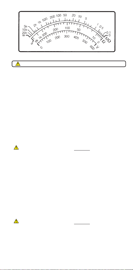
3. Read the voltage measurement from the voltmeter scale.
4. Carefully disconnect the test leads.
Low Resistance measurement (Ω)
1. Select Ω with the rotary selector switch.
2. Ensure that all test leads are clean and in good condition, and connect
them to the
isolated circuit under test.
3. Any pointer deflection indicates a live circuit
, and testing should be
aborted.
4. Press the ‘
Test’push, and keep it pressed while turning the generator
handle.
5. Read the measurement from the
kΩ scale.
6. Disconnect the test leads.
Insulation Testing (MΩ)
Automatic circuit discharge is effective when the test button is released, and
decaying voltage is indicated by the scale needle until the circuit is
discharged.
1. Select
MΩ with the rotary selector switch.
2. Ensure that all test leads are clean and in good condition, and connect
them to the
isolated circuit under test.
3. Any pointer deflection indicates a live circuit
, and testing should be
aborted.
4. Press the ‘
Test’ button, and keep it pressed while turning the generator
handle.
5. Read the measurement from the
MΩ scale.
6. Release the ‘
Test’push and monitor any scale needle movement to
confirm when any discharging voltage decays to zero.
7. When the circuit has discharged, disconnect the test leads.
Refer to Safety Warnings before using the instrument
MEASUREMENT SCALES
Page 3

Using the Guard Terminal
For basic insulation tests and where there is little possibility of surface
leakage affecting the measurement, it is unnecessary to use the guard
terminal.
In cable testing, there may be surface leakage paths across the insulation
between the bare cable and the external sheathing due to the presence of
moisture or dirt. Where it is required to remove the effect of this leakage,
particularly at high testing voltages, a bare wire may be bound tightly around
the insulation and connected via the third test lead to the guard terminal ‘G’.
The guard terminal is at the same potential as the negative terminal. Since the
leakage resistance is effectively in parallel with the resistance to be
measured, the use of the guard causes the current flowing through surface
leakage to be diverted from the measuring circuit. The instrument therefore
reads the leakage of the insulator, ignoring leakage across its surface.
SPECIFICATION
Insulation Ranges
Measuring Ranges: 0 - 20,000 MΩ at all test voltages
Test Voltages (d.c.): 100 V; 250 V; 500 V; 1kV on open circuit
Test V. Accuracy: ±5%
Short Cct. Current: 220 µA nominal on all ranges
Accuracy: ±3% of scale length on a 3.08 inch arc length
Low resistance Range
Measuring Range: 0 - 5000 Ω
Open Cct. Voltage: 3 V ± 5%
Short Cct. Current: 30 mA ± 10%
Accuracy: ±3% of scale length on a 3.08 inch arc length
Default Voltage measurement
Range: 0 - 600 V a.c.
Accuracy: ±2.5% of scale length
General Specifications
Overload rating: The 210170 is protected for connection to Power
distribution systems up to 300 V Line - Ground, and
500 V Line - Line for Installation Category III*.
Terminal Characteristics
Leakage path
to ‘+’ve
terminal
to ‘G’
terminal
to ‘-’ve
terminal
Tightly bound bare wire
Page 4

Temp. Range:
Operating: 14°F to 122°F
Storage: 4°F to 158°F
Humidity:
Operating: 70% RH at 68°F, 50% RH at 104°F
Storage: 95% RH at 95°F
Automatic Discharge: Capacitive circuits are automatically discharged when
the ‘Test’push is released following an insulation
test.
Power Supply: Low voltage brushless a.c. generator
Fuses: 2 x 500 mA (F) 500 V H.B.C. 10 kA min 11⁄4“ x 1⁄4“
To check these fuses, short all three test leads together and set the rotary
selector switch on any Insulation test position. Press the ‘Test’push and keep
it pressed while turning the generator handle. The needle should register
approximately 2 MΩ. Azero reading indicates that the ‘G’ fuse has ruptured.
An Infinity reading indicates that the +ve fuse has ruptured.
Fuse Replacement: Held in a screw type holder located in the base of the
instrument. Use a flat blade screwdriver to release the center part of the
holder, and remove the ruptured fuse. Replace with fuse(s) of the correct type,
size and rating.
Weight: 2.2 lb
Dimensions: 81⁄4” (including generator handle) x 5” x 5”
Cleaning: Wipe disconnected instrument with a clean cloth
dampened with soapy water or Isopropyl Alcohol IPA)
*Relates to transient overvoltage likely to be found in fixed installation wiring.
ACCESSORIES
Supplied Part Number
User Guide 6172-382
Test lead set comprising:-
1 black, 1 red, 1 green test lead, with alligator clips 6220-436
Test Record Card (5 supplied) 6172-111
Optional
Carrying case 217740
Fuses (500mA) x 5 6121-289
Fused probe kit
FPK8 6111-287
Test lead set 6220-436
Test Record cards (Pack of 20) 6111-216
Publication - ‘A Stitch in Time’ AVTM21-P8B
0.5A(F) 500V
HBC(10 kA)
Guard fuse
Positive fuse
Page 5

REPAIR AND WARRANTY
The instrument contains static sensitive devices, and care must be taken in
handling the printed circuit board. If an instrument’s protection has been
impaired it should not be used, but sent for repair by suitably trained and
qualified personnel. The protection is likely to be impaired if for example; it
shows visible damage; fails to perform the intended measurements; has been
subjected to prolonged storage under unfavourable conditions, or has been
subjected to severe transport stresses.
NEW INSTRUMENTS ARE GUARANTEED FOR 1 YEAR
FROM THE DATE OF PURCHASE BY THE USER.
Note: Any unauthorized prior repair or adjustment will automatically invalidate
the Warranty.
INSTRUMENT REPAIR AND SPARE PARTS
For service requirements for Megger Instruments contact :-
Megger or Megger Limited
Valley Forge Corporate Center Archcliffe Road
2621 Van Buren Avenue Dover
Norristown, PA19403 Kent, CT17 9EN
U.S.A. England
Tel: +1 (610) 676-8579 Tel: +44 (0) 1304 502243
Fax: +1 (610) 676-8625 Fax: +44 (0) 1304 207342
or an approved repair company.
Approved Repair Companies.
A number of independent instrument repair companies have been authorised
for repair work on most Megger instruments, using genuine Megger spare
parts. Consult the Appointed Distributor / Agent regarding spare parts, repair
facilities, and advice on the best course of action to take.
Returning an Instrument for Repair
If returning an instrument to the manufacturer for repair, it should be sent
freight pre-paid to the appropriate address. Acopy of the invoice and of the
packing note should be sent simultaneously by airmail to expedite clearance
through Customs. Arepair estimate showing freight return and other charges
will be submitted to the sender, if required, before work on the instrument
commences.
Page 6

M
Archcliffe Road
Dover
Kent CT17 9EN Tel: +44 (0) 1304 502100
England Fax: +44 (0) 1304 207342
2621 Van Buren Avenue
Norristown
PA19403 Tel: +1 (610) 676-8500
U.S.A. Fax: +1 (610) 676-8610
4271 Bronze Way
Dallas
TX 75237-1017 Tel: +1 (800) 723-2861 (U.S.A. only)
U.S.A. Tel: +1 (214) 330-3203 (International)
Fax: +1 (214) 337-3038
Megger
29 Allée de Villemomble,
93340 Le Raincy
Paris Tel: +33 (1) 43.02.37.54
France Fax: +33 (1) 43.02.16.24
This instrument is manufactured in the United Kingdom.
The company reserves the right to change the specification or design without prior notice.
Megger is a registered trademark.
Part No. 6172-382 - Edition 5 - Printed in England - 0703
 Loading...