

Megatron MTH-2500, MTH-3500, MTH-2700 User Manual
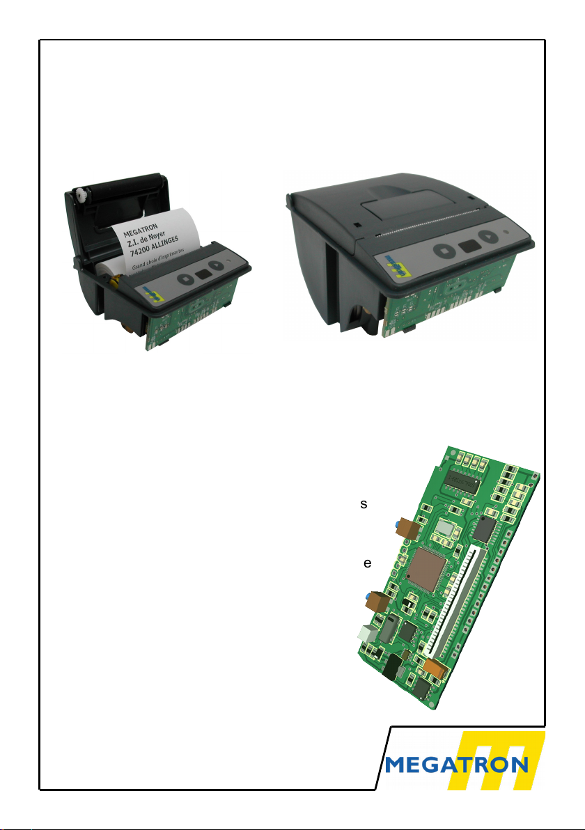
MTH-2500, 2700 & 3500
THERMAL PRINTERS
WITH ELM-208 HEAD
● Interface TTL serial RS232C RS422
USB 2.0 Ethernet Parallel etc...
● Protocol: None or Modbus (RTU)
● Paper case Ø 31 mm or Ø 60 mm
● High definition and fast printing
● Bar codes and Graphic printing capabilities
● 24 and 42 characters per line
● 2 downloadable character sets
● Logo downloading and printing via interface
or by closing a dry contact
● 5 VDC or 9 to 40 VDC supply voltage
● Setup by menu or interface
● Temperature control of the printing head
● Windows 10, 8.1, 8, 7, Vista, XP
● Selftest and hexadecimal dump
Version 3.4 – english
MTH-2500
MTH-3500

SUMMARY
1 General information.......................................................................................3
1.1 Printer operation.........................................................................................3
1.2 Material Description.................................................................................... 4
1.3 Part number............................................................................................... 4
1.4 Technical data............................................................................................5
1.5 Print Head Technical Data......................................................................... 6
2 Wiring Information.........................................................................................7
2.1 DC 5V Power Supply.................................................................................. 7
2.2 DC 9-40 V Power Supply........................................................................... 7
2.3 Serial TTL and RS232C............................................................................. 8
2.4 USB............................................................................................................9
2.5 RS422 Serial.............................................................................................. 9
2.6 Other Interfaces.......................................................................................... 9
2.7 Backup Battery.........................................................................................10
2.8 Rewinder.................................................................................................. 10
2.9 Ext Input................................................................................................... 10
3 Printer Operation.........................................................................................11
3.1 Start-Up....................................................................................................11
3.2 System Reinitialization (RESET)..............................................................11
3.3 Paper Loading..........................................................................................11
3.4 Control Panel............................................................................................ 11
3.5 Self Test or Hexadecimal Dump...............................................................12
4 Characters & Commands............................................................................13
4.1 Character Set........................................................................................... 13
4.2 Printer Language or Compatibility............................................................14
4.3 MTH Commands...................................................................................... 15
4.4 PCL Raw command................................................................................. 27
4.5 Labels....................................................................................................... 28
5 Appendix.....................................................................................................30
5.1 Dimensions and Cut-out...........................................................................30
5.2 Cables and Papers...................................................................................32
5.3 MTH-2500 in special cases......................................................................33
5.4 Status LED............................................................................................... 34
5.5 Setup Menu..............................................................................................35
5.6 Modbus.................................................................................................... 39
5.7 Documentation revisions..........................................................................39
MTH-2500, 2700 & 3500 v3.4 2
PRELIMINARY NOTE
Because of the evolution of standards and technologies and in a permanent concern for
improvement, Megatron reserves itself the right to modify the characteristics of the device
described in this document without advanced notice.

1 GENERAL INFORMATION
1.1 PRINTER OPERATION
The basic idea for the conception of the MTH-2500 printer, was to push
miniaturization as far as possible. The whole printer: case - head - interface
holds in the volume of a big matchbox and consists of very robust elements.
Small size also implies a small dimension for the paper roll, and also the
change of paper was optimized to be extremely simple: you just need to
open the upper lid, insert the paper roll and push the lid back to its initial
position.
Could it be more simple?
MTH-3500 printer as the same basis with a greater paper case (Ø 60 mm).
Thanks to this greater size, this printer can use labels rolls.
Numerous features are enclosed in the management software of the printer
allowing for the printing of graphs and bar codes as well as numerous special
effects.
Bonus:
ü A 8K-bytes logo can be stored in the flash memory. The printing of this
logo can be made through the printer interface or by closing a separate
dry contact.
ü Two character sets are embarked to allow you to vary your printed tickets.
ü A very simple to implement graphic mode allows you to realize nice
curves without complicated calculation.
ü Windows 10, 8.1, 8, Seven, Vista, XP, 2K drivers are available and can be
downloaded from our web site. This driver uses graphic compression tiff4
to increase the printing speed. It allows to select printing between paper
or labels rolls. These drivers are unsigned , please disable the protection
of drivers signed under the recent Windows to allow installation.
The printing speed and the silence of operation makes it the ideal instrument
for point of sale terminals, ticket machines, cash registers and medical
applications.
The 203 dpi density ( 8 points/mm ) authorizes the printing of graphs, curves
and bar codes with excellent quality and resolution.
3 MTH-2500, 2700 & 3500 v3.4
1.2 MATERIAL DESCRIPTION
The printer is designed around a Microchip PIC18F67J50 microprocessor,
128K-bytes of flash ROM and 3904 Bytes of RAM (2k-bytes are reserved for
the receive buffer). An internal watchdog in the microprocessor is activated to
insure an operation in strongly polluted industrial environment.
The printer can be connected in serial in TTL or RS232C levels, RS422
(without protocol or Modbus over serial), in USB 2.0, in Ethernet
(Raw TCP/IP) ou (ModBus over TCP) or in parallel. Characters received by
the interface are stored in its memory and interpreted by the micro-processor.
Different features such as line-feed and menu buttons, control LED, paperend detector and rewinder are directly driven by the MTH-2500, MTH-2700 or
MTH-3500 printers.
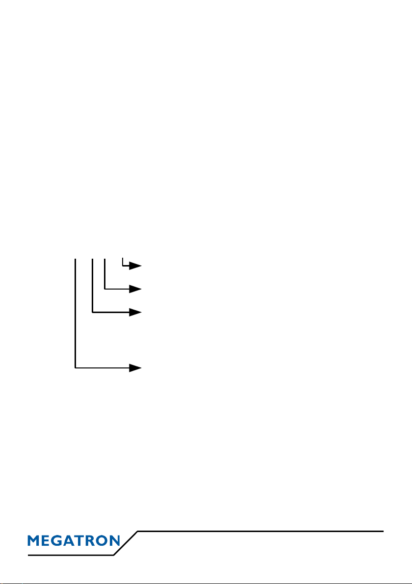
1.3 PART NUMBER
Several versions of the electronics are available. To completely define your
product, it is necessary to add a suffix to the name of the printer to specify the
selected computer connection
(P1)
Logic VCC and Power VPP must be supplied in 5VDC. To use a unique
supply, please consult our AN117 application note on our web site.
(P2)
Power supply is unique and must be any value between DC 9 to 40 V.
MTH-2500, 2700 & 3500 v3.4 4
MTH- xx1x2x3- x
c
Time Clock
[C] : installed [ ] : not installed
Power Supply
[1] : DC 5 V
(P1)
[3] : from DC 9 to 40 V
(P2)
Interface
[1] : TTL serial [2] : RS232C serial
[4] : Parallel [6] : USB
[7] : Ethernet (Printing TCP/IP) [8] : RS422 (without protocol
[9] : Ethernet (ModBus over TCP) or Modbus over serial)
Paper case & Enclosure
[25] : standard for Ø 31 mm
[27] : standard for Ø 31 mm in DIN 96x96 case
[35] : Deep for Ø 60 mm

1.4 TECHNICAL DATA
Character sets IBM-II
Text print speed 7 character lines / second
Character size (H x W) H= 3mm (24 dots) x
W= 2mm (16 dots) or 1,125mm (9 dots)
Interfaces
Serial
TTL Level : 0/5V
RS232C/V24 Level : ± 12V
Handshake : XON/XOFF and RTS/CTS
RS422 Level : 0/5V
Protocols : Without Protocol (Receive only)
or Modbus over serial
USB version 2.0
Printer class
Parallel Handshake Busy
Paper-End
Ethernet
Printing TCP/IP Lantronix Xport module
Modbus over TCP Lantronix Xport-IAP module
MTH-xxx1 Power supply DC 5 V
Consumption Waiting mode 90 mA
Black printing ~3 A
MTH-xxx3 Power supply from DC 9 to 40 V
Consumption Waiting mode 50 mA (under DC 12V)
Black printing ~1,5 A ( under DC 12V)
for MTH-2xxx
Weight (without roll) ~75 g
Size in mm 77 x 77 x 40 ( W x D x H )
Operating temperature 0 to 50°C
Paper MPA-TH-57-31-TL-SB
for MTH-3xxx
Weight (without roll) ~105 g
Size in mm 77 x 113 x 70 ( W x D x H )
Operating temperature 0 to 50°C
Paper MPA-TH-57-50-1
5 MTH-2500, 2700 & 3500 v3.4
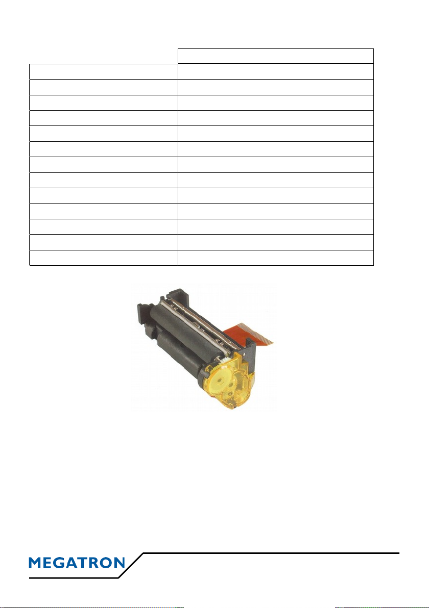
1.5 PRINT HEAD TECHNICAL DATA
ELM208-HS
Technology
Thermal
Power supply Head 5,5-9,5 V / Logic 3-5,25 V
Paper width
58 mm
Dots / line
384
Printing density 203 dpi (8 points / mm)
Characters / line 24 or 42 according to selected font
Distance between dots
0,125 mm
Distance between lines
0,125 mm (two motor steps )
Head temperature sensor Thermistor on the head
Paper-end sensor Reflective optical sensor
Life 100 x 106 pulses, 50 kms
Dimensions in mm
68 x 22 x 31
Weight
~ 40 g
MTH-2500, 2700 & 3500 v3.4 6
ELM-208-HS
2 WIRING INFORMATION
2.1 DC 5V POWER SUPPLY
Supply must be connected on CN2
(type Molex KK – 5 pins male connector at 2.54mm step)
CN2 Power supply
8 VPP (power)
9 VPP (power)
10 GND
11 GND
12 VCC (Logic)
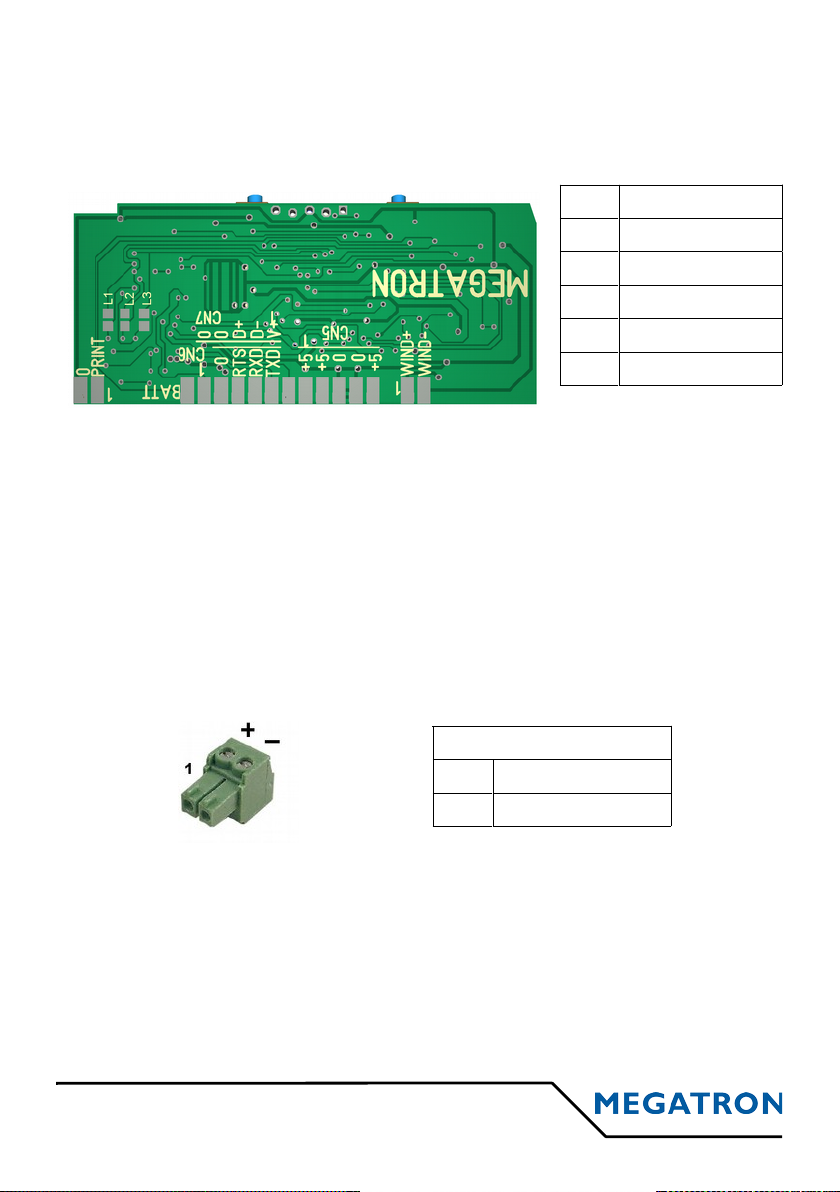
2.2 DC 9-40 V POWER SUPPLY
Basis board is only powered in DC 5V. To add DC 9-40 V Power supply, we
install add-on cards directly fixed under the bottom of the printer case.
Power supply connector is similar on all the add-on cards. It is a 2 pins
connector (Phoenix MCV105/12G at 3,81mm step). Corresponding "Power
Supply" connector is delivered with the printer. It is a "Miniconnec MC 1,5/2ST-3,81" and can be mounted without special tool.
Depending of the versions, add-on cards can offer other fonctionnalities like
parallel interface, Ethernet interface, RS485, Communication Class USB
interface and battery support for the clock chip and so on...
7 MTH-2500, 2700 & 3500 v3.4
CN2
5V 8
5V 9
GND 10
GND 11
5V 12
Alimentation 9-40 VDC
1 VPP (DC 9-40 V)
2 GND

2.3 SERIAL TTL AND RS232C
TTL serial connections in 0/5V levels must be connected
on CN2 : type Molex KK – 4 pins male at 2.54mm step
Available on MTH-2500 & 3500
Not available on MTH-2700
RS232C serial connections in ± 12V levels must be connected
on CN2 : type Molex KK – 4 pins male at 2.54mm step
for MTH-2500 & MTH-3500 without add-on card
PAPER END MONITORING
• If a paper-end occurs, a 19h character is sent on the serial interface.
• When a new paper roll is installed, a XON character (11h) is sent on
the serial interface
MTH-2500, 2700 & 3500 v3.4 8
CN2
GND 3
RTS 4
RXD 5
TXD 6
5 4 3 2 1
9 8 7 6
n.c.
n.c.
n.c.
n.c.
RTS
RxD
TxD
n.c.
GND
on the add-on card
for MTH-2500 & 3500 with add-on card
at the back of the DIN96x96 enclosure
for MTH-2700
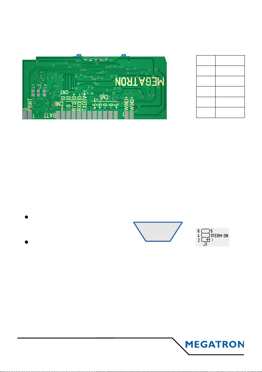
For information: RS232C serial is active if bridges L1, L2 and L3
are opened and U1 component : MAX-232 is present.
For information: TTL serial is active if bridges
L1, L2 and L3 are closed and U1 component :
MAX-232 is absent.
CN2 SERIAL WAY
3 GND -
4 RTS Output
5 RXD Input
6 TXD Output
On Sub-D 9 pins female socket :
2.4 USB
USB interface apply to the USB 2.0 specifications and answer to the Printer
Class. USB interface is powered directly by the printer. It can be connected in
CN2 (type Molex KK – 4 pins males at 2.54mm step)
Except when ordering specific housing including its USB connectivity,
the printer comes with a small USB cord with a female socket type A,
length ~ 18cm .
2.5 RS422 SERIAL
Two modes are possible : « Without protocol » (only the data reception is
possible) or in « Modbus over serial » ( voir § 5.6)
2.6 OTHER INTERFACES
Other interfaces are available on add-on cards. They are not described in this
manual but in others specific manuals delivered with your product:
9 MTH-2500, 2700 & 3500 v3.4
n.c.
n.c.
n.c.
Bridge 3-4 adds a 120 Ω
terminator resistor.
on the add-on card
for MTH-2500 & 3500
n.c.
n.c.
Bridges 1-2 and 5-6 can be
closed for polarise A and B
lines.
A/RX-
B/RX+
C/Gnd
CN2
GND 2
GND 3
D+ 4
D- 5
VUSB 6
Note:
VUSB input is not used to powered the printer
but only to detect if the host computer is present.
A/RX-
at the back of the DIN96x96 enclosure
for MTH-2700
5 4 3 2 1
9 8 7 6
CN2 USB
2 GND
3 GND
4 D+
5 D-
6 VUSB
On Sub-D 9 pins female socket :
• Parallel interface on a Sub-D 25 pins socket
• Ethernet Raw TCP/IP interface
• Ethernet ModBus over TCP interface
• etc...
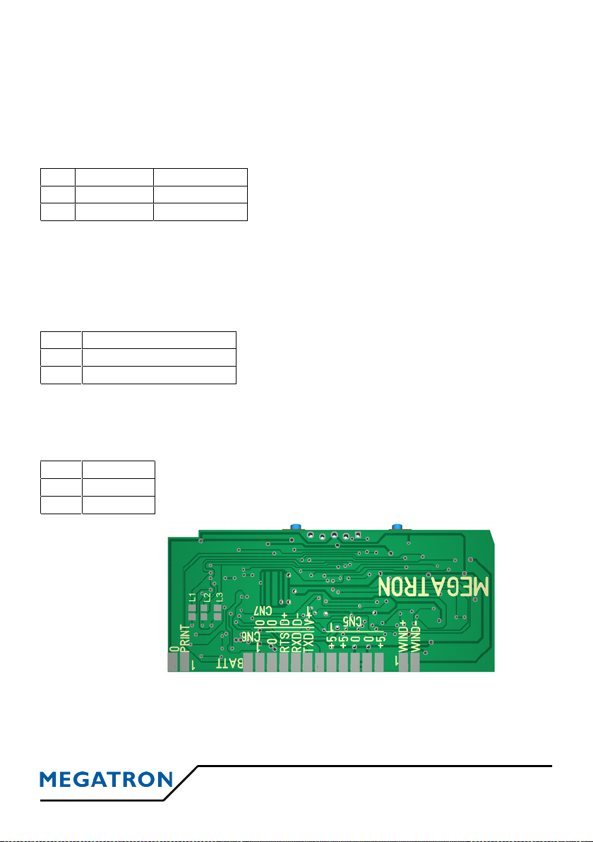
2.7 BACKUP BATTERY
Only for printer versions with incorporated clock, to preserve the clock
settings, a DC 3 V battery must be connected to CN2 (type Molex KK – 2
pins at 2.54 step).
A battery holder and its battery can installed by our factory service on an
additional card, depending on options chosen.
CN2 BATTERY POLARITY
1 BAK + +
3 BAK - -
2.8 REWINDER
The rewinder of the MP-200-60-62 serie allows the rolling-up of the printed
paper for archiving. Their DC 5 V supply voltage is supplied by the printer.
To connect on CN4 (type Molex KK – 2 pins at 2.54 step)
CN4 REBOBINEUR
References: Rewinder
MP-210-60-62: without fastening stands
MP-220-60-62: with fastening stands
1 Rewinder + (VCC)
2 Rewinder - (Signal)
2.9 EXT INPUT
Ext input is available on CN3 (type Molex KK – 2 pins at 2.54 step).
CN3 Ext Input
Advanced->Ext input menu allows to choose the use of
the Ext input on CN3 connector between Not Used,
Print Logo, Analog Input (ADC) and Counting Input (CPT).
1 GND
2 EXT
MTH-2500, 2700 & 3500 v3.4 10
CN3
GND 1
EXT 2
CN4
WIND+ 1
WIND- 2
CN2
BAT+ 1
2
GND 3
3 PRINTER OPERATION
3.1 START-UP
1. Connect the power supply and connection cables
2. Turn power on
The interface will control its memory, set its parameters according to the data
menu stored in its Flash memory, look for the possible presence of a clock
circuit and moves the printing head 8 steps to synchronize the step motor. At
the end of this initialization cycle, the printer is ready for receiving characters.
3.2 SYSTEM REINITIALIZATION (RESET)
The printer is designed with a watchdog which makes a reset at power-up
authorizing the use of a slow ascent supply. About 300 milli-seconds after the
controller is powered-up, this one is ready for operation, having ended its
reset cycle.
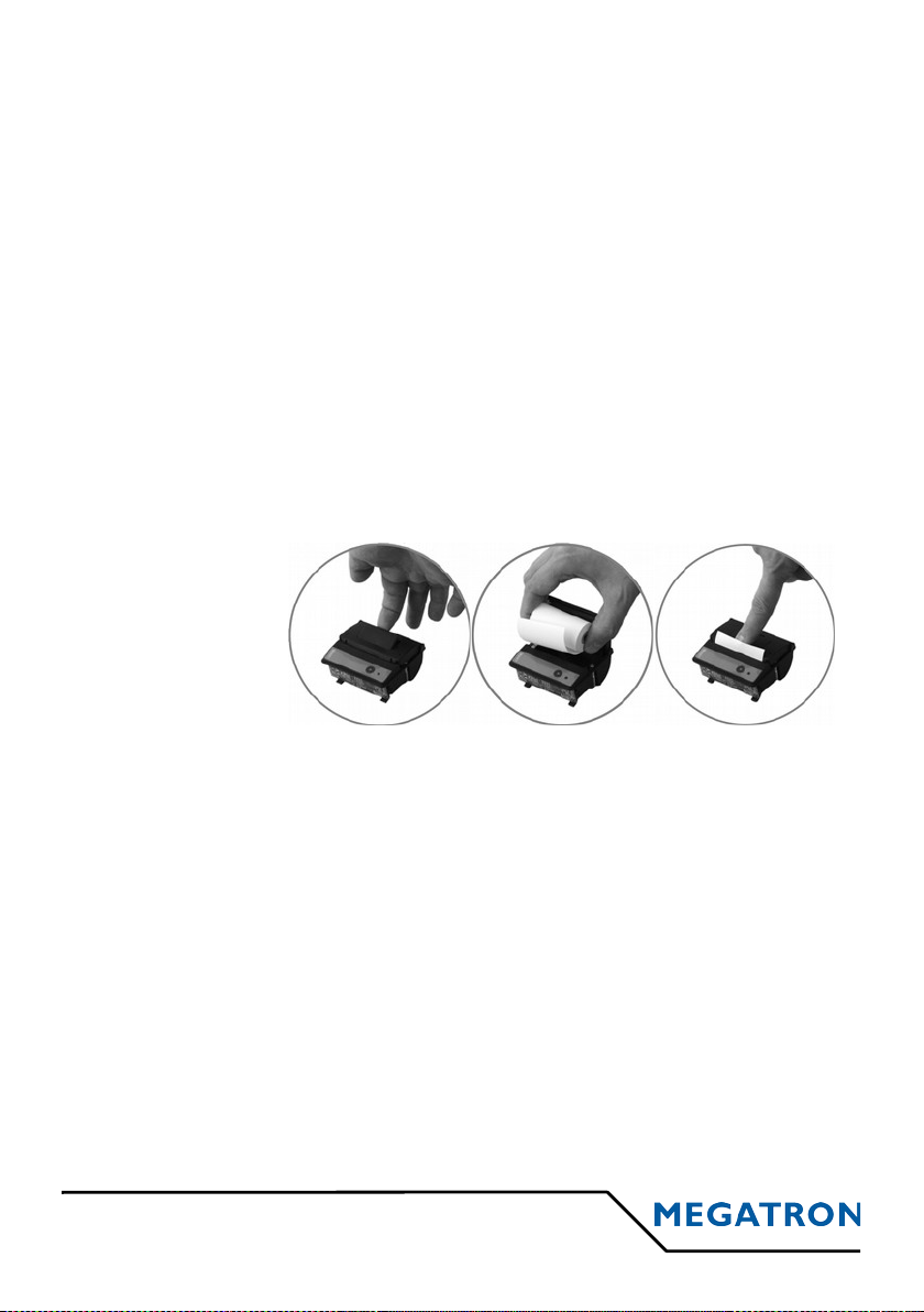
3.3 PAPER LOADING
• Open the printer
• Remove the old
paper roll
• Install the new
paper roll
• Close the printer
3.4 CONTROL PANEL
The control panel allows the user to interact with the printer with two
pushbuttons and a status light.
• Button ► is used to feed the paper, to do the self-test of the printer, to
activate the hex dump mode (§ 3.5) and for the setup menu (§ 5.5).
• Button ■ is used for the setup menu (§ 5.5).
• The bicolour LED informs the user of any malfunctions. A continuous
GREEN light indicates proper operation, a flashing RED light informs an
anomaly whose description is detailed in the table in § 5.6.
11 MTH-2500, 2700 & 3500 v3.4
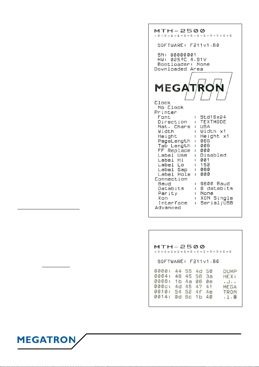
3.5 SELF TEST OR HEXADECIMAL DUMP
If, after a reset, the linefeed button ► is
maintained pushed, a special cycle is run.
The printer starts by printing the 4 first lines
of the self test then wait until the button ► is
released.
Selftest :
Simply release the button ► without other
actions, the printer goes into self-test cycle.
Printer parameters and character set ate
printed. The selftest gives only a probability
of correct operation of the printer; indeed, the
selftest procedure does not use transmission,
this one can only be tested in real mode.
Then connect interface and power supply.
The printer is ready for use !
Here is an example
of partial selftest→
Hexadecimal Dump:
Depressed the button ■ before releasing the
button ►, the printer will switch to hexadecimal dump mode. It will print the
text "HEX DUMP:”
In this mode, the hexadecimal values of
successive characters are printed in a first
column and their ASCII shapes in a second
column. Warning: the control codes are not
interpreted any more. This mode is used for
connection debugging. Each line begins by a
characters counter (also in hexadecimal).
A hexadecimal dump is implemented in the
printer. This mode can be activated for a long
time by setting the setup menu :
Advanced->Compatible on HEXA.
MTH-2500, 2700 & 3500 v3.4 12
Dump Hexa Example
 Loading...