

Page 1
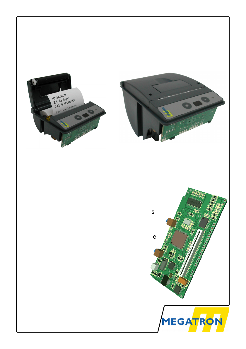
MTH-2500, 2700 & 3500
THERMAL PRINTERS
WITH ELM-208 HEAD
● Interface TTL serial RS232C RS422
USB 2.0 Ethernet Parallel etc...
● Protocol: None or Modbus (RTU)
● Paper case Ø 31 mm or Ø 60 mm
● High definition and fast printing
● Bar codes and Graphic printing capabilities
● 24 and 42 characters per line
● 2 downloadable character sets
● Logo downloading and printing via interface
or by closing a dry contact
● 5 VDC or 9 to 40 VDC supply voltage
● Setup by menu or interface
● Temperature control of the printing head
● Windows 10, 8.1, 8, 7, Vista, XP
● Selftest and hexadecimal dump
Version 3.4 – english
MTH-2500
MTH-3500
Page 2

SUMMARY
1 General information.......................................................................................3
1.1 Printer operation.........................................................................................3
1.2 Material Description.................................................................................... 4
1.3 Part number............................................................................................... 4
1.4 Technical data............................................................................................5
1.5 Print Head Technical Data......................................................................... 6
2 Wiring Information.........................................................................................7
2.1 DC 5V Power Supply.................................................................................. 7
2.2 DC 9-40 V Power Supply........................................................................... 7
2.3 Serial TTL and RS232C............................................................................. 8
2.4 USB............................................................................................................9
2.5 RS422 Serial.............................................................................................. 9
2.6 Other Interfaces.......................................................................................... 9
2.7 Backup Battery.........................................................................................10
2.8 Rewinder.................................................................................................. 10
2.9 Ext Input................................................................................................... 10
3 Printer Operation.........................................................................................11
3.1 Start-Up....................................................................................................11
3.2 System Reinitialization (RESET)..............................................................11
3.3 Paper Loading..........................................................................................11
3.4 Control Panel............................................................................................ 11
3.5 Self Test or Hexadecimal Dump...............................................................12
4 Characters & Commands............................................................................13
4.1 Character Set........................................................................................... 13
4.2 Printer Language or Compatibility............................................................14
4.3 MTH Commands...................................................................................... 15
4.4 PCL Raw command................................................................................. 27
4.5 Labels....................................................................................................... 28
5 Appendix.....................................................................................................30
5.1 Dimensions and Cut-out...........................................................................30
5.2 Cables and Papers...................................................................................32
5.3 MTH-2500 in special cases......................................................................33
5.4 Status LED............................................................................................... 34
5.5 Setup Menu..............................................................................................35
5.6 Modbus.................................................................................................... 39
5.7 Documentation revisions..........................................................................39
MTH-2500, 2700 & 3500 v3.4 2
PRELIMINARY NOTE
Because of the evolution of standards and technologies and in a permanent concern for
improvement, Megatron reserves itself the right to modify the characteristics of the device
described in this document without advanced notice.
Page 3

1 GENERAL INFORMATION
1.1 PRINTER OPERATION
The basic idea for the conception of the MTH-2500 printer, was to push
miniaturization as far as possible. The whole printer: case - head - interface
holds in the volume of a big matchbox and consists of very robust elements.
Small size also implies a small dimension for the paper roll, and also the
change of paper was optimized to be extremely simple: you just need to
open the upper lid, insert the paper roll and push the lid back to its initial
position.
Could it be more simple?
MTH-3500 printer as the same basis with a greater paper case (Ø 60 mm).
Thanks to this greater size, this printer can use labels rolls.
Numerous features are enclosed in the management software of the printer
allowing for the printing of graphs and bar codes as well as numerous special
effects.
Bonus:
ü A 8K-bytes logo can be stored in the flash memory. The printing of this
logo can be made through the printer interface or by closing a separate
dry contact.
ü Two character sets are embarked to allow you to vary your printed tickets.
ü A very simple to implement graphic mode allows you to realize nice
curves without complicated calculation.
ü Windows 10, 8.1, 8, Seven, Vista, XP, 2K drivers are available and can be
downloaded from our web site. This driver uses graphic compression tiff4
to increase the printing speed. It allows to select printing between paper
or labels rolls. These drivers are unsigned , please disable the protection
of drivers signed under the recent Windows to allow installation.
The printing speed and the silence of operation makes it the ideal instrument
for point of sale terminals, ticket machines, cash registers and medical
applications.
The 203 dpi density ( 8 points/mm ) authorizes the printing of graphs, curves
and bar codes with excellent quality and resolution.
3 MTH-2500, 2700 & 3500 v3.4
Page 4
1.2 MATERIAL DESCRIPTION
The printer is designed around a Microchip PIC18F67J50 microprocessor,
128K-bytes of flash ROM and 3904 Bytes of RAM (2k-bytes are reserved for
the receive buffer). An internal watchdog in the microprocessor is activated to
insure an operation in strongly polluted industrial environment.
The printer can be connected in serial in TTL or RS232C levels, RS422
(without protocol or Modbus over serial), in USB 2.0, in Ethernet
(Raw TCP/IP) ou (ModBus over TCP) or in parallel. Characters received by
the interface are stored in its memory and interpreted by the micro-processor.
Different features such as line-feed and menu buttons, control LED, paperend detector and rewinder are directly driven by the MTH-2500, MTH-2700 or
MTH-3500 printers.
1.3 PART NUMBER
Several versions of the electronics are available. To completely define your
product, it is necessary to add a suffix to the name of the printer to specify the
selected computer connection
(P1)
Logic VCC and Power VPP must be supplied in 5VDC. To use a unique
supply, please consult our AN117 application note on our web site.
(P2)
Power supply is unique and must be any value between DC 9 to 40 V.
MTH-2500, 2700 & 3500 v3.4 4
MTH- xx1x2x3- x
c
Time Clock
[C] : installed [ ] : not installed
Power Supply
[1] : DC 5 V
(P1)
[3] : from DC 9 to 40 V
(P2)
Interface
[1] : TTL serial [2] : RS232C serial
[4] : Parallel [6] : USB
[7] : Ethernet (Printing TCP/IP) [8] : RS422 (without protocol
[9] : Ethernet (ModBus over TCP) or Modbus over serial)
Paper case & Enclosure
[25] : standard for Ø 31 mm
[27] : standard for Ø 31 mm in DIN 96x96 case
[35] : Deep for Ø 60 mm
Page 5

1.4 TECHNICAL DATA
Character sets IBM-II
Text print speed 7 character lines / second
Character size (H x W) H= 3mm (24 dots) x
W= 2mm (16 dots) or 1,125mm (9 dots)
Interfaces
Serial
TTL Level : 0/5V
RS232C/V24 Level : ± 12V
Handshake : XON/XOFF and RTS/CTS
RS422 Level : 0/5V
Protocols : Without Protocol (Receive only)
or Modbus over serial
USB version 2.0
Printer class
Parallel Handshake Busy
Paper-End
Ethernet
Printing TCP/IP Lantronix Xport module
Modbus over TCP Lantronix Xport-IAP module
MTH-xxx1 Power supply DC 5 V
Consumption Waiting mode 90 mA
Black printing ~3 A
MTH-xxx3 Power supply from DC 9 to 40 V
Consumption Waiting mode 50 mA (under DC 12V)
Black printing ~1,5 A ( under DC 12V)
for MTH-2xxx
Weight (without roll) ~75 g
Size in mm 77 x 77 x 40 ( W x D x H )
Operating temperature 0 to 50°C
Paper MPA-TH-57-31-TL-SB
for MTH-3xxx
Weight (without roll) ~105 g
Size in mm 77 x 113 x 70 ( W x D x H )
Operating temperature 0 to 50°C
Paper MPA-TH-57-50-1
5 MTH-2500, 2700 & 3500 v3.4
Page 6
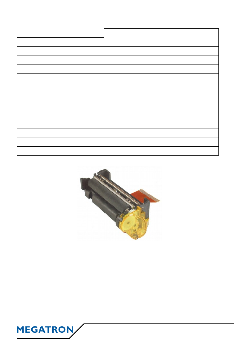
1.5 PRINT HEAD TECHNICAL DATA
ELM208-HS
Technology
Thermal
Power supply Head 5,5-9,5 V / Logic 3-5,25 V
Paper width
58 mm
Dots / line
384
Printing density 203 dpi (8 points / mm)
Characters / line 24 or 42 according to selected font
Distance between dots
0,125 mm
Distance between lines
0,125 mm (two motor steps )
Head temperature sensor Thermistor on the head
Paper-end sensor Reflective optical sensor
Life 100 x 106 pulses, 50 kms
Dimensions in mm
68 x 22 x 31
Weight
~ 40 g
MTH-2500, 2700 & 3500 v3.4 6
ELM-208-HS
Page 7
2 WIRING INFORMATION
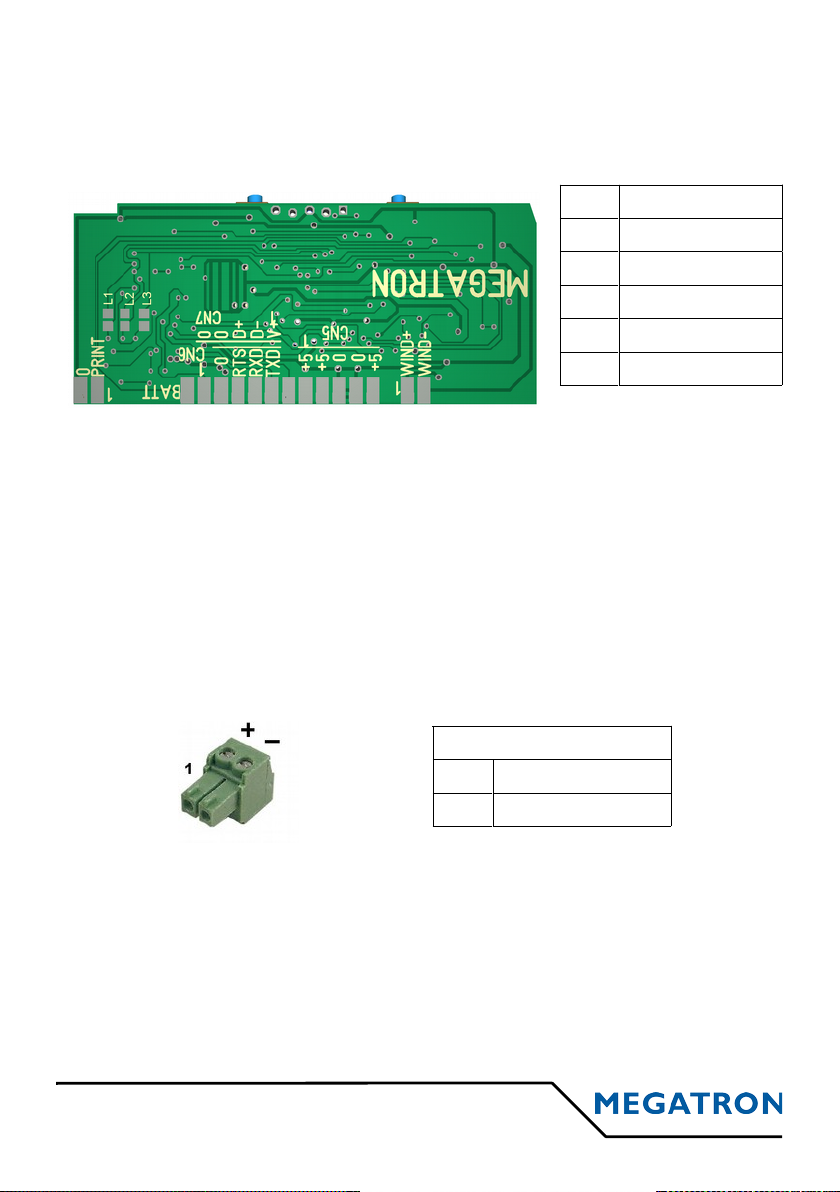
2.1 DC 5V POWER SUPPLY
Supply must be connected on CN2
(type Molex KK – 5 pins male connector at 2.54mm step)
CN2 Power supply
8 VPP (power)
9 VPP (power)
10 GND
11 GND
12 VCC (Logic)
2.2 DC 9-40 V POWER SUPPLY
Basis board is only powered in DC 5V. To add DC 9-40 V Power supply, we
install add-on cards directly fixed under the bottom of the printer case.
Power supply connector is similar on all the add-on cards. It is a 2 pins
connector (Phoenix MCV105/12G at 3,81mm step). Corresponding "Power
Supply" connector is delivered with the printer. It is a "Miniconnec MC 1,5/2ST-3,81" and can be mounted without special tool.
Depending of the versions, add-on cards can offer other fonctionnalities like
parallel interface, Ethernet interface, RS485, Communication Class USB
interface and battery support for the clock chip and so on...
7 MTH-2500, 2700 & 3500 v3.4
CN2
5V 8
5V 9
GND 10
GND 11
5V 12
Alimentation 9-40 VDC
1 VPP (DC 9-40 V)
2 GND
Page 8

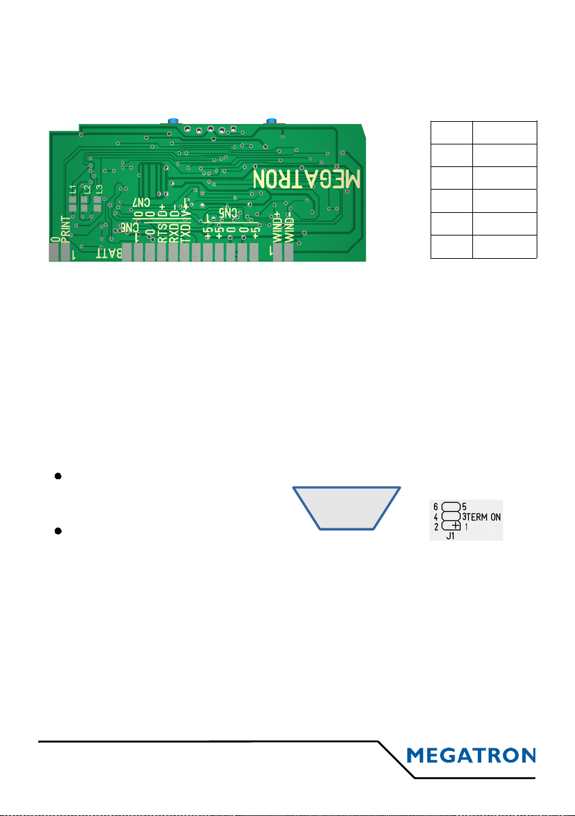
2.3 SERIAL TTL AND RS232C
TTL serial connections in 0/5V levels must be connected
on CN2 : type Molex KK – 4 pins male at 2.54mm step
Available on MTH-2500 & 3500
Not available on MTH-2700
RS232C serial connections in ± 12V levels must be connected
on CN2 : type Molex KK – 4 pins male at 2.54mm step
for MTH-2500 & MTH-3500 without add-on card
PAPER END MONITORING
• If a paper-end occurs, a 19h character is sent on the serial interface.
• When a new paper roll is installed, a XON character (11h) is sent on
the serial interface
MTH-2500, 2700 & 3500 v3.4 8
CN2
GND 3
RTS 4
RXD 5
TXD 6
5 4 3 2 1
9 8 7 6
n.c.
n.c.
n.c.
n.c.
RTS
RxD
TxD
n.c.
GND
on the add-on card
for MTH-2500 & 3500 with add-on card
at the back of the DIN96x96 enclosure
for MTH-2700
For information: RS232C serial is active if bridges L1, L2 and L3
are opened and U1 component : MAX-232 is present.
For information: TTL serial is active if bridges
L1, L2 and L3 are closed and U1 component :
MAX-232 is absent.
CN2 SERIAL WAY
3 GND -
4 RTS Output
5 RXD Input
6 TXD Output
On Sub-D 9 pins female socket :
Page 9
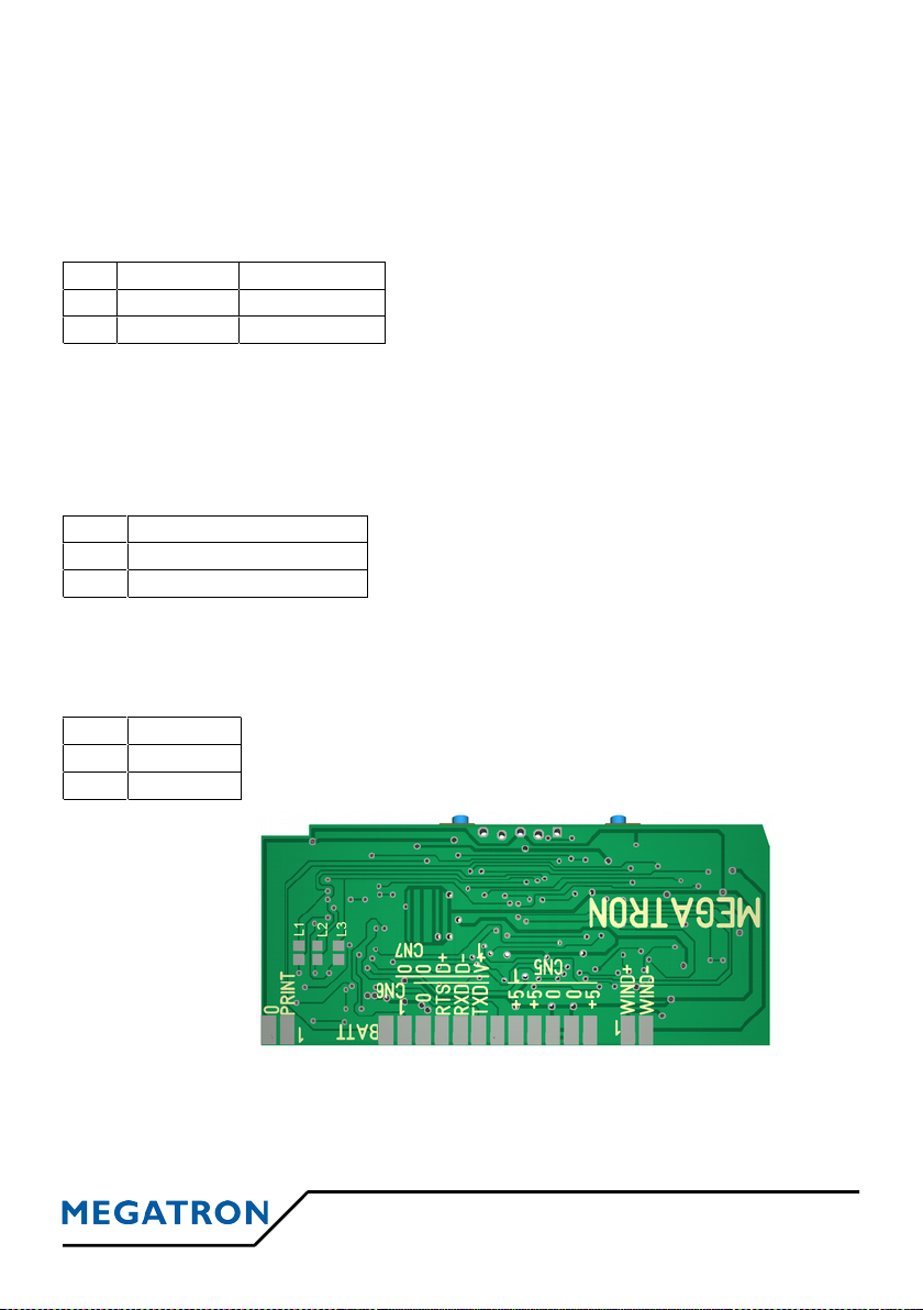
2.4 USB
USB interface apply to the USB 2.0 specifications and answer to the Printer
Class. USB interface is powered directly by the printer. It can be connected in
CN2 (type Molex KK – 4 pins males at 2.54mm step)
Except when ordering specific housing including its USB connectivity,
the printer comes with a small USB cord with a female socket type A,
length ~ 18cm .
2.5 RS422 SERIAL
Two modes are possible : « Without protocol » (only the data reception is
possible) or in « Modbus over serial » ( voir § 5.6)
2.6 OTHER INTERFACES
Other interfaces are available on add-on cards. They are not described in this
manual but in others specific manuals delivered with your product:
9 MTH-2500, 2700 & 3500 v3.4
n.c.
n.c.
n.c.
Bridge 3-4 adds a 120 Ω
terminator resistor.
on the add-on card
for MTH-2500 & 3500
n.c.
n.c.
Bridges 1-2 and 5-6 can be
closed for polarise A and B
lines.
A/RX-
B/RX+
C/Gnd
CN2
GND 2
GND 3
D+ 4
D- 5
VUSB 6
Note:
VUSB input is not used to powered the printer
but only to detect if the host computer is present.
A/RX-
at the back of the DIN96x96 enclosure
for MTH-2700
5 4 3 2 1
9 8 7 6
CN2 USB
2 GND
3 GND
4 D+
5 D-
6 VUSB
On Sub-D 9 pins female socket :
• Parallel interface on a Sub-D 25 pins socket
• Ethernet Raw TCP/IP interface
• Ethernet ModBus over TCP interface
• etc...
Page 10
2.7 BACKUP BATTERY
Only for printer versions with incorporated clock, to preserve the clock
settings, a DC 3 V battery must be connected to CN2 (type Molex KK – 2
pins at 2.54 step).
A battery holder and its battery can installed by our factory service on an
additional card, depending on options chosen.
CN2 BATTERY POLARITY
1 BAK + +
3 BAK - -
2.8 REWINDER
The rewinder of the MP-200-60-62 serie allows the rolling-up of the printed
paper for archiving. Their DC 5 V supply voltage is supplied by the printer.
To connect on CN4 (type Molex KK – 2 pins at 2.54 step)
CN4 REBOBINEUR
References: Rewinder
MP-210-60-62: without fastening stands
MP-220-60-62: with fastening stands
1 Rewinder + (VCC)
2 Rewinder - (Signal)
2.9 EXT INPUT
Ext input is available on CN3 (type Molex KK – 2 pins at 2.54 step).
CN3 Ext Input
Advanced->Ext input menu allows to choose the use of
the Ext input on CN3 connector between Not Used,
Print Logo, Analog Input (ADC) and Counting Input (CPT).
1 GND
2 EXT
MTH-2500, 2700 & 3500 v3.4 10
CN3
GND 1
EXT 2
CN4
WIND+ 1
WIND- 2
CN2
BAT+ 1
2
GND 3
Page 11
3 PRINTER OPERATION
3.1 START-UP
1. Connect the power supply and connection cables
2. Turn power on
The interface will control its memory, set its parameters according to the data
menu stored in its Flash memory, look for the possible presence of a clock
circuit and moves the printing head 8 steps to synchronize the step motor. At
the end of this initialization cycle, the printer is ready for receiving characters.
3.2 SYSTEM REINITIALIZATION (RESET)
The printer is designed with a watchdog which makes a reset at power-up
authorizing the use of a slow ascent supply. About 300 milli-seconds after the
controller is powered-up, this one is ready for operation, having ended its
reset cycle.
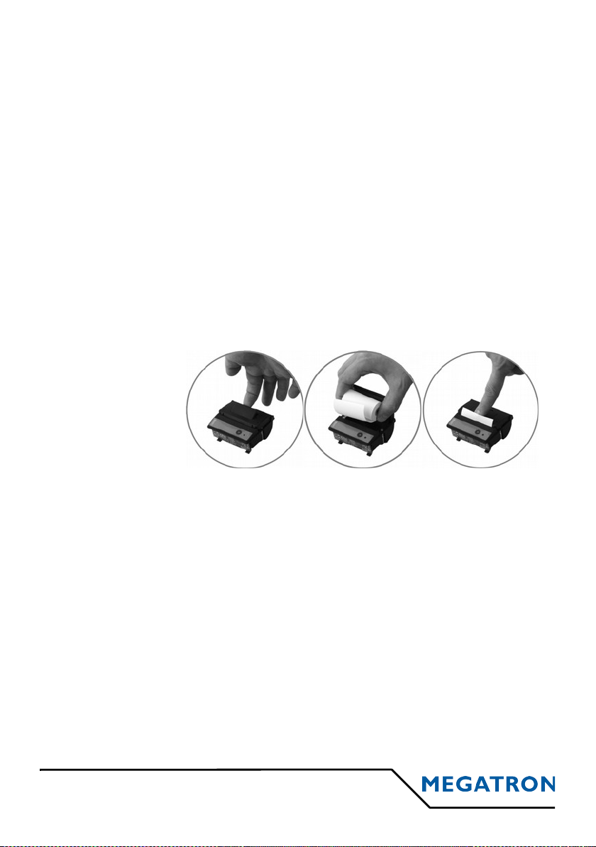
3.3 PAPER LOADING
• Open the printer
• Remove the old
paper roll
• Install the new
paper roll
• Close the printer
3.4 CONTROL PANEL
The control panel allows the user to interact with the printer with two
pushbuttons and a status light.
• Button ► is used to feed the paper, to do the self-test of the printer, to
activate the hex dump mode (§ 3.5) and for the setup menu (§ 5.5).
• Button ■ is used for the setup menu (§ 5.5).
• The bicolour LED informs the user of any malfunctions. A continuous
GREEN light indicates proper operation, a flashing RED light informs an
anomaly whose description is detailed in the table in § 5.6.
11 MTH-2500, 2700 & 3500 v3.4
Page 12
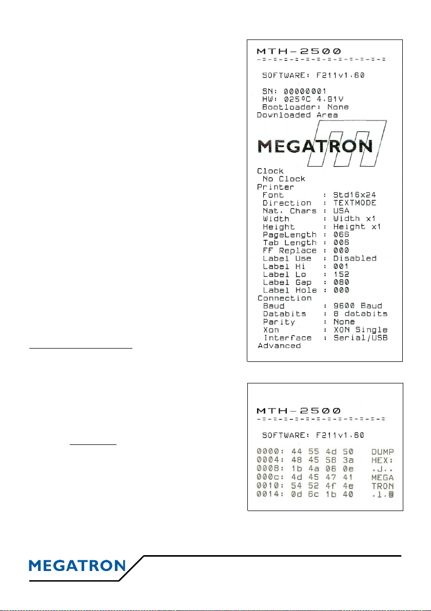
3.5 SELF TEST OR HEXADECIMAL DUMP
If, after a reset, the linefeed button ► is
maintained pushed, a special cycle is run.
The printer starts by printing the 4 first lines
of the self test then wait until the button ► is
released.
Selftest :
Simply release the button ► without other
actions, the printer goes into self-test cycle.
Printer parameters and character set ate
printed. The selftest gives only a probability
of correct operation of the printer; indeed, the
selftest procedure does not use transmission,
this one can only be tested in real mode.
Then connect interface and power supply.
The printer is ready for use !
Here is an example
of partial selftest→
Hexadecimal Dump:
Depressed the button ■ before releasing the
button ►, the printer will switch to hexadecimal dump mode. It will print the
text "HEX DUMP:”
In this mode, the hexadecimal values of
successive characters are printed in a first
column and their ASCII shapes in a second
column. Warning: the control codes are not
interpreted any more. This mode is used for
connection debugging. Each line begins by a
characters counter (also in hexadecimal).
A hexadecimal dump is implemented in the
printer. This mode can be activated for a long
time by setting the setup menu :
Advanced->Compatible on HEXA.
MTH-2500, 2700 & 3500 v3.4 12
Dump Hexa Example
Page 13

4 CHARACTERS & COMMANDS
4.1 CHARACTER SET
Two complete sets of 255 IBM-II characters are available in ROM as well as
national characters. Characters exist in 16x24 and 9x24 matrix allowing 24
and 42 characters by line with uppercase and lowercase letters.
The selection of national characters is done by software or by the setup
menu.
Other fonts can be uploaded in the printer to replace existing fonts. Every
other fonts or sizes (maxi 16x24) are conceivable like Cyrillic, Greek, Kanji,
etc...
Ask to our technical department for special fonts.
13 MTH-2500, 2700 & 3500 v3.4
Standard 16x24
Standard - Matrix16x24
Standard 9x24
Page 14

4.2 PRINTER LANGUAGE OR COMPATIBILITY
MTH: The default printer language is called MTH. It is near ESC/P commands
essentially in text printing. In graphic, only one horizontal dot line is printed at
once while ESC/P mode uses 8 or 24 vertical dot lines.
PCL: Last mode is PCL Raw. Only the graphic raw modes are interpreted
with several compression types : No compression, Run Length, Tiff and Delta
Row. A graphical scaling mode is implemented to fit large graphic printouts in
the width of the printer.
EPS24 Lite: This mode is reserved to special applications.
It is not a full Epson 24 needles compatibility.
Hexa: In this mode, the hexadecimal values of successive characters are
printed in a first column and their ASCII shapes in a second column. Warning:
the control codes are not interpreted any more. This mode is used for
connection debugging. Each line begins by a characters counter (also in
hexadecimal). This mode can be temporary activated at the power-up (see
chapter 3.5).
MTH-2500, 2700 & 3500 v3.4 14
CP737 - Greek CP855 – Eastern Europe CP866 - Russian
Handy FontTimes Font Modern Font
Page 15

4.3 MTH COMMANDS
The characters with their ASCII values between 01 hex and 1F hex are
control characters and are printable only in transparent mode (see command
ESC T n).
4.3.1 CHARACTER SET
· ESC F n (1B 46 Hex = 27 70 Dec)
Select one of the 2 character fonts.
Only the two lower bits of n allow to
select the font. Equal to 0 for font 0; different for font 1.
· ESC R n (1B 52 Hex = 27 82 Dec)
Select national characters.
Default choice is selectable by the setup menu.
n
NATION 23 40 5B 5C 5D 5E 60 7B 7C 7D 7E
0 U.S.A.
# @ [ \ ] ^ ` { | } ~
1 France
# à ° ç § ^ ` é ù è "
2 Germany
# § Ä Ö Ü ^ ` ä ö ü ß
3 Great-Britain
£ @ [ \ ] ^ ` { | } ~
4 Denmark 1
# @ Æ Ø Å ^ ` æ ø å ~
5 Sweden
# É Ä Ö Å Ü é ä ö å ü
6 Italy
# @ ° \ é ^ ù à ò è ì
7 Spain
Pt @ ¡ Ñ ¿ ^ ` ˝ ñ } ~
8 Japan
# @ [ ¥ ] ^ ` { | } ~
9 Norway
# É Ä Ö Å Ü é ä ö å ü
10 Denmark 2
# É Ä Ö Å Ü é ä ö å ü
11 Netherland
£ @ [ IJ ] ^ ` { ij } ~
· ESC T n (1B 54 Hex = 27 84 Dec)
Print next character in transparent mode. Character n is not interpreted as
control character but is directly printed. This command allow printing of
characters with values smaller than 20 Hex (32 Dec).
15 MTH-2500, 2700 & 3500 v3.4
n Font Char/line
0 0: Std_16x24 24
1 to 3 1: Std_09x24 42
Page 16

4.3.2 CHARACTERS ENRICHMENT
· SO (0E Hex = 14 Dec)
Double width of characters
· DC4 (14 Hex = 20 Dec)
Simple width of characters
· ESC - n (1B 2D Hex = 27 45 Dec)
Beginning / End of underline
n = 1 (01 Hex) or '1' (31 Hex) Beginning of underline
n = 0 (00 Hex) or '0' (30 Hex) End of underline
· ESC W n (1B 57 Hex = 27 87 Dec)
Widening of the characters
The default value of n is 0 (normal size).
The maximum value depends on the actual font size and the margins :
MATRIX n MAX. ENLARGEMENT
16 x 24 23 24 times
12 x 24 31 32 times
9 x 24 41 42 times
If n is too big, widening is set to the maximal possible width.
· ESC o n (1B 6F Hex = 27 111 Dec)
Graphic design of the zero
n = 1 (01 Hex) or '1' (31 Hex) Slashed zero (default value).
n = 0 (00 Hex) or '0' (30 Hex) Non slashed zero.
· ESC w n (1B 77 Hex = 27 119 Dec)
Lengthening of the characters
The default value of n is 0 (normal size).
The maximum value of n is 9 (10 x the normal height)
· ESC l n (1B 6C Hex = 27 108 Dec)
Setting the left margin in mm.
The byte n represents the distance in millimeters from the left edge of the
printing zone. This setting is independant from the text or data printing
modes. Be careful, right and left margins only affect text printing, and do
not affect graphic and bar code printing.
MTH-2500, 2700 & 3500 v3.4 16
Page 17

· ESC r n (1B 72 Hex = 27 114 Dec)
Setting the right margin in mm.
The byte n represents the distance in millimeters from the right edge of the
printing zone. This setting is independant from the text or data printing
modes. Be careful, right and left margins only affect text printing, and do
not affect graphic and bar code printing
· ESC { n (1B 7B Hex = 27 123 Dec)
Setting of the mode Text/Data
n = 1 (01 Hex) ou '1' (31 Hex) Data mode
n = 0 (00 Hex) ou '0' (30 Hex) Text mode (default setting)
The text or data default mode is setup by the setup menu
· ESC I n (1B 49 Hex = 27 73 Dec)
Choice of printing contrast
n < 128, printing becomes brighter
n= 128, printing is normal
n > 128, printing becomes darker
4.3.3 HORIZONTAL SPACES
· TAB (09 Hex = 9 Dec)
Tabulation
Move the next printing position to the next tabulation.
· ESC D x
1
...xi NUL (1B 44 ... 00 Hex = 27 68 ... 0 Dec)
Tabulations setting.
You can define as many tabulations positions xi than the number of
characters that can be defined in the line of characters. This command
must end with the NULL character (00 Hex).
By default, tabulations are positioned every 6 characters in 6, 12, 18,
etc...). This value can be changed by the setup menu.
17 MTH-2500, 2700 & 3500 v3.4
Page 18

4.3.4 VERTICAL SPACES
· LF (0A Hex = 10 Dec)
Starting a new line.
The LF (Line Feed) and CR (Carriage Return) characters act the same
way by triggering the printing of the current line. Some word processing
softwares use LF, others CR and a few others both commands to trigger a
line printing. In order to avoid non required double interline spacing, in
case a sequence including these two consecutive characters is received,
only the first character received will trigger the printing, the other one will
be ignored.
· FF (0C Hex = 12 Dec)
In normal mode, starts a new page. See ESC C command.
In label mode, moves the roll at the beginning of the next label.
See GS P n command.
· CR (0D Hex = 13 Dec)
Carriage return.
Starting a new line. See LF command above.
· ESC ) n (1B 29 Hex = 27 41 Dec)
Advancing for n character lines
· ESC 2 (1B 32 Hex = 27 50 Dec)
Return to the default space between the lines. (default value = 0)
· ESC 3 n (1B 33 Hex = 27 51 Dec)
Setting the space between two character lines to n dot lines
(n x 0.125 mm)
· ESC 5 n (1B 35 Hex = 27 53 Dec)
No effect
(only for compatibility with previous software versions)
· ESC C n (1B 43 Hex = 27 67 Dec)
Setting the page length in lines of characters.
The default value is set by the setup menu.
· ESC J n (1B 4A Hex = 27 74 Dec)
Advancing for n dot lines (n x 0.125 mm).
MTH-2500, 2700 & 3500 v3.4 18
Page 19

4.3.5 GRAPHICS
· ESC f (1B 66 Hex = 27 102 Dec)
Printing a black line.
· ESC K n x
1
...xn (1B 4B ... Hex = 27 75 ... Dec)
Line by line graphic printing.
n represents the number of characters of the
graphic string. The characters string x1 to x
n
represents the desired printed pattern. All
the bits of received characters are printed on
the same line.
Text and Data mode enrichment (ESC '{' n) and vertical lengthening mode
(ESC 'w' n) only have an effect in graphic mode. In Text mode, the line is
printed from left to right with the higher weight’s bits to the far left. In Data
mode, the line is printed from right to left with the higher weight’s bits to the
far right. Characters and graphics cannot be printed on the same line.
The graphic data transmission can be transmitted non-compressed or using
tiff4 pack-bits compression mode (see ESC 'm' command).
· ESC m n (1B 6D ... Hex = 27 109 ... Dec)
Setting of the graphic compression mode tiff4.
n = 0 (00 Hex) or '0' (30 Hex) No compression (default mode)
n ≠ 0 (00 Hex) or '0' (30 Hex) Tiff4 compression
19 MTH-2500, 2700 & 3500 v3.4
Not compressed example: ESC K <30h>ABC...X
Text Mode
Data Mode
Megatron logo printed
Page 20

· ESC ' m
L mH nL1 nH1
.. nLm nHm (1B 27 Hex=27 39 Dec)
Printing graphic curves.
This command allows for easy printing of curves along the paper
(vertically). The m value (transmitted on 2 bytes) represents the number of
curves (points) to be printed for the current graphic line, and must be
included between 1 and the maximum number of printable points per line
(384).
The n1 .. nm values represent the position of these m curves (or points); the
number of points (n1 .. nm) must be equal to m.
Each point must be included between 1 and the maximum number of
printable points per line (384), otherwise it will not be printed. As horizontal
lines printing progresses, the vertical curves will show on the paper.
The vertical lengthening (ESC 'w' n) act on the graphic curves.
Example: Basic software to print 4 curves and a central axis.
· y = 192 + e
-0,1x
· y = 192 - e
-0,1x
· y = 192 - e
-0,1x
* sin (x/10)
· y = 192 + e
-0,1x
* sin (x/10)
· y = 192
MTH-2500, 2700 & 3500 v3.4 20
Software in Basic
10 OPEN "COM1:9600, N, 8, 1, CS60000, DS, CD" AS #1
20 FOR X=0 TO 200
30 PRINT #1, CHR$(27); CHR$(39); CHR$(5); CHR$(0);
40 Y=INT(192*EXP(-.01*X)): YY=INT(Y*SIN(X/10))
50 PRINT #1, CHR$((192-YY) mod 256);CHR$((192-YY) div 256);
60 PRINT #1, CHR$((192-Y) mod 256);CHR$((192-Y) div 256);
70 PRINT #1, CHR$(192);CHR$(0);
80 PRINT #1, CHR$((192+Y) mod 256);CHR$((192+Y) div 256);
90 PRINT #1, CHR$((192+YY) mod 256);CHR$((192+YY) div 256);
100 NEXT X
110 CLOSE #1
120 END
Page 21

4.3.6 LOGO
An 8K-bytes logo can be stored in the flash memory.
This logo can contain all of the characters and control sequences of the
printer: enrichments, texts, graphics, graphic lines, bar codes, etc.... Only the
backup, logo call, and reboot commands of the printers cannot be used.
Our software "ProgMessage" can help you to upload your own logo !
· GS s m
L mH n1
.. nm (1D 73 Hex=29 115 Dec) ou
ESC s mL mH n1 .. nm (1B 73 Hex=27 115 Dec)
Storing the logo in the Flash memory.
m (transmitted on 2 bytes) contains the number of bytes of the logo.
n1 .. nm are the n bytes constituting the logo
The m value is mL + 256 x mH and must not exceed 8K-bytes - 2 bytes are
reserved for the logo space!
· ESC p (1B 70 Hex=27 112 Dec)
Printing the logo.
· Logo printing can be activated by closing to ground the Ext Input on CN3
connector if menu Advanced->Ext input is set to « Print Logo »
4.3.7 LABELS COMMAND
Label mode works when 'Label Use' setup menu is enabled and parameters :
'Label height', 'Hole Height' and 'Label Gap' are correctly set.
See chapter Labels for more details (chapter 4.5).
· FF (0C Hex = 12 Dec)
In label mode, set the roll position at the start of the next label.
See 'GS P n' command.
In normal mode, Starts a new page. See ESC 'C' command.
· GS P n (1D 50 Hex = 29 80 Dec)
Positioning labels command
If n is even, this command feeds the roll at the start of the next label
except if it is not yet on the start of a label.
Same as FF in Label mode.
if n is odd, this command feeds the roll at the start of the next label
whatever its actual position.
21 MTH-2500, 2700 & 3500 v3.4
Page 22

4.3.8 BAR CODE
· ESC " 0 x1...xn (1B 22 00 ... FF Hex = 27 34 0 ... 255 Dec)
Printing the chain x1 to xn as a bar code.
This command must be ended by the FF Hex
= 255 Dec character.
Remark: If the chain contains a non authorized
character or if the resulting bar code exceeds
the paper width, the bar code drawing is replaced by a simple grey pattern
and the erroneous character is replaced by a '?' in the HRI characters.
Example in CODE 39: ESC " 0 MEGATRON
so in hex: 1B 22 30 4D 45 47 41 54 52 4F 4E FF
· ESC " 1 n (1B 22 01 n Hex = 27 34 1 n Dec)
Setting the bar code type
n
Bar Code Authorized characters
4 (04H) CODE 39 0 to 9, A...Z, Space,$,%,*,+,-,/,.
by default
5 (05H) Interleaved 2 in 5 0 to 9 (even number of characters)
6 (06H) CODABAR 0 to 9, A,B,C,D,E,N,T,$,+,-,=,/,.
Example: Setting CODE 39 ESC " 1 4
so in hex: 1B 22 31 34 or 1B 22 01 04
· ESC " 2 n (1B 22 02 n Hex = 27 34 2 n Dec)
Enlargement factor of the bar code where n+1 represents the enlargement
factor ( n between 0 and 3). The default value of n is 0.
Example: Set Enlargement to 1 ESC " 2 1
so in hex: 1B 22 32 31 or 1B 22 02 01
· ESC " 3 n (1B 22 03 n Hex = 27 34 3 n Dec
Height of the bar code where n represents the
number of dot lines of the bar code.
The default value for the height is 48,
therefore 48 * 0.25 mm = 12 mm.
All the n values included between 1 and 255 are available.
Example: Set height to 60 lines ESC " 3 <
so in hex: 1B 22 33 3C or 1B 22 03 3C
MTH-2500, 2700 & 3500 v3.4 22
Page 23

· ESC " 4 n (1B 22 04 n Hex = 27 34 4 n Dec)
Printing Human Readable Information (HRI) on the bar code
n
HRI
0 No printing
1 Printing after (default)
2
Printing before
ç
3
Printing before and after
Characters are printed with active enrichments (width, height), starting at
the same left position than the bar code. The HRI characters going over the
line are not printed.
Remark: only the 2 lowest significant bits are tested.
Example: HRI before ESC " 4 2
so in hex: 1B 22 34 32 or 1B 22 04 02
· ESC " 5 n (1B 22 05 n Hex = 27 34 5 n Dec)
Bar code offset in millimeters.
The n value by default is 0. Its maximum value
is the number of millimeters of the printing
area of the connected printing head minus 1.
The position of the bar code is independant
from the right and left margins.
Example: 7 mm offset ESC " 5 07h
so in hex: 1B 22 35 07 or 1B 22 05 07
23 MTH-2500, 2700 & 3500 v3.4
Page 24

4.3.9 VARIOUS COMMANDS
· CAN (18 Hex = 24 Hex)
Cancelling the printing of previous characters.
· ESC @ (1B 40 Hex = 27 64 Dec)
Software reboot.
All the settings are re-set to their default value.
· GS v n (1D 76 Hex = 29 118 Dec) ou
ESC v n (1B 76 Hex = 27 118 Dec)
Printer interrogation on serial interface.
When receiving this sequence, the printer
sends a parameter corresponding to the n
value back on the serial interface.
No effect in parallel or USB interface.
· ESC = n (1B 3D Hex = 27 61 Dec)
Regrouping / Degrouping the strobes.
n = 1 (01 Hex) or '1' (31 Hex)
Regrouping the strobes
n = 0 (00 Hex) or '0' (30 Hex) Degrouping the strobes
Default value is set by the setup menu.
Degrouping the strobes: to reduce the average power consumption of
the printer, by default, the 6 strobes driving the printing head are
successively driven one after the other. While printing text, the average
power consumption is reduced to the detriment of the printing speed.
Grouping the strobes: to increase the printing speed, several command
strobes of the printing head can be grouped without exceeding the printers
capability. Caution: the power consumption is then at the maximum level.
· GS <FD> <zone> <Low> <High> <datas> (1D FD Hex=29 253 Dec) ou
ESC <FD> <zone> <Low> <High> <datas> (1B FD Hex=27 253 Dec)
Flash memory area upload (Font, Logo, Parameters, etc...)
(This command is reserved to the factory)
Warning: reprogramming above can not be used without consultation of our
technical services! May damage the printer !
MTH-2500, 2700 & 3500 v3.4 24
n
0 Printer name
1 Software and version
2 Manufacturer
3 Current date and time
4 Voltage
5 Head Temperature
6 Paper Sensor
7 Printer serial number
8 EXT0 value
Parameter
Page 25

4.3.10 SETUP COMMAND
· GS ] n
1 n2 n3
(1D 5D Hex = 29 93 Dec) ou
ESC ] n1 n2 n3 (1B 5D Hex = 27 93 Dec)
Setup command followed by 3 bytes n1 n2 n3.
n1 : - if n1 = 0 (00 hex) or n1 >=127 (7F hex)
Backup setup in Flash memory.
The two bytes n2 and n3 are not necessary.
- between 1 (01 hex) and the number of groups
Select the setup group
n2 : Select the setup field
between 1 (01 hex) and the number of fields
n3 : Set the new value for the selected field.
- if there are several choices:
between 1 (01h) and the number of choices
- if it is a number: a number in the authorized area
See the menu summary table for the different choices of Groups, Fields
and Values.
Warning: The time setting is not allowed with this command !
Use ESC 'c' command for the clock setting.
For an easier setting, the setup information are sent by the printer on the
serial line followed by a “carriage return” character (0D hex).
Example: GS ] 03h 01h 08h set, in the group 'Serial',
the Field 'Baud' at the 8th choice: '9600 Baud'.
The printer send on the serial line:
Serial ->Baud =9600 Baud
GS ] 00h asks the backup in the Flash memory.
The printer send on the serial line:
FLASH CONFIGURATION
If a value is false, a specific error message is sent
on the serial line by the printer:
GROUP Out of range ! , FIELD Out of range !,
VALUE Out of range ! , NOTHING TO FLASH !,
Clock ->xxxxx = Not allowed !
25 MTH-2500, 2700 & 3500 v3.4
Page 26

4.3.11 CLOCK OPTION
To obtain the printing of date and hour, it is possible to install a time clock,
with a battery backup. The interface part number will contain the -C extension.
For example: MTH2521-C. The time clock can be set over the computer
interface, or thanks to the setup menu.
Tip: Time can be sent back on the computer liaison with the GS 'v' 3
· ESC c 0 x
1
... x12 (1B 63 30 ... Hex = 27 99 48 ... Dec)
Setting the real time clock.
With x1... x12 ASCII code between 30 and 39 Hex (characters 0 to 9)
At the reception of this command, the clock switches to the set-up mode
and the twelve bytes x1... x12 represent the chain DDMMYYHHMMSS
(Day, Month, Year, Hour, Minute and Second ).
The clock can only be set-up at the beginning of a line.
· ESC c 1 (1B 63 31 Hex = 27 99 49 Dec)
Printing the date.
At the reception of this command, the date is stored in the printing buffer
at its current position.
The format of the date depends on the selected characters set :
MM-DD-YY : USA, Great-Britain, Japan (ex: 02-13-04)
DD.MM.YY : Other characters sets (ex: 13.02.04)
If the clock is not present or faulty, the printed date is 00-00-00.
· ESC c 2 (1B 63 32 Hex = 27 99 50 Dec)
Printing the time without the seconds.
At the reception of this command, the time is stored in the printing buffer at
its current position.
The time format is HH:MM'.
If the clock is not present or faulty, the printed time is 00:00'.
· ESC c 3 (1B 63 33 Hex = 27 99 51 Dec)
Printing the time with the seconds.
At the reception of this command, the time is stored in the printing buffer at
its current position.
The time format is HH:MM'SS".
If the clock is not present or faulty, the printed time is 00:00'00".
MTH-2500, 2700 & 3500 v3.4 26
Page 27

4.4 PCL RAW COMMAND
PCL Raw compatibility is implemented to allow connections on computers or
terminals where installing new drivers is not possible and PCL is embedded.
Only the graphic functions are optimized in this mode.
Other PCL commands are ignored.
Graphical compressions Run Length, Tiff and Delta Row are supported.
Mnenomics Hexa PCL commands implemented
ESC "&" 1B 26
ESC "&" "a" # "H" Horizontal position
ESC "*" 1B 2A
ESC "*" "b" # "W" Graphic print
ESC "*" "b" # "M" Select graphic compression
(No compression, Run Length, Tiff, Delta Row)
ESC "*" "r" # "T" Set page length
ESC "*" "p" # "X" Set horizontal position
ESC "*" "p" # "Y" Set vertical position
ESC "E" 1B 45 Software reset
PCL commands ignored : ESC "!" ESC "#" ESC "$"
ESC "%" ESC "(" ESC ")" ESC "+" ESC "/" ESC "."
Remarque: Les autres commandes du mode Megatron qui n'ont pas
d'équivalent PCL peuvent toujours être utilisées.
A graphical scale mode is implemented in the printer.
• For horizontal scale, set "Advanced" -> "Horz Scale" menu.
Scale factor is calculated on one byte, i.e. on 8 consecutive columns
of the transmitted graphic.
All the graphic line is analysed 8 columns at a time.
Example:
• to print 1 column on 2,
set "Horz Scale" to "Scale 50%"
• to print 1 column on 4,
set "Horz Scale" to "Scale 25%".
• For vertical scale, set "Advanced" -> " Vert Scale" menu. It works
like horizontal scale but on 8 consecutive lines of the transmitted
graphic. Generally, it is used to keep the Ratio Horizontal/Vertical.
• Limiting the number of blank lines in PCL. The number of the setup
menu "Advanced"-> "Blank PCL #" limits the amount of consecutive
empty dotlines points to this value (0 to disable).
27 MTH-2500, 2700 & 3500 v3.4
Page 28

4.5 LABELS
Label mode is available only with MTH-3500 printer because its paper roll
diameter is bigger. It is enable by setting menu Printer -> Label Use on
Enabled.
This mode change the printer operating :
● Paper-end optical sensor is used to detect the holes between the
labels. The maximal hole height is 10 mm. A hole greater than 11 mm
is interpreted as a Paper End.
● Depress on LF button feeds the label roll to the start of the next label.
● Form feed command (0Ch) feeds the label roll to the start of a label.
Page length parameter is not used in this mode. Other commands are
explained in chapter 4.3.7
● If no hole is detected during a too long length of paper, an error is
sent to the user with the LED. May be, it is not a label roll but a paper
roll or the paper-end optical sensor is defect.
Note: The printer mechanism doesn't allow to use black marks, labels rolls
must use holes between the labels. The begin of the hole is used to detect the
start of a label.
Some parameters have to be set in the Printer menu to allow a good
detection of the labels :
Label Use : Printer uses the label mode or not
Label Gap : Inter-labels spaces, between 16 and 255
(mini recommended 64)
Label Hi: High part of the Label height, between 0 and 3
Label Lo: Low part of the Label height, between 0 and 255
Label Hole: Spaces between the end of a label and the start of the hole,
between 0 and 56
Remember: All distances are in dot lines,
i.e.: distance in mm / 0.125.
MTH-2500, 2700 & 3500 v3.4 28
Page 29

Labels rolls details
Holes: The holes must be
● Centred at 13.5 mm of the right paper edge.
● Minimum 3 mm width
● Height between 2 and 10 mm. To recognize a paper-end of a hole,
holes must have a height <11mm i.e.: <88 dot lines (88 x 0.125mm).
● Margin E ('Label Hole') between label end and the start of a hole can
be set (between 0 and 56 dot lines, i.e. between 0 and 7 mm)
Inter-Labels Spaces G or 'Label Gap':
● Height between 2 and 31,8 mm. Suggested >= 8 mm.
● Feed back is not recommended. To immediately unglue the last
printed label, we recommend a 8 mm minimum of inter-Labels spaces
G ('Label Gap') even if the actual distance is smaller; but you lose
some part of the top of the next label
Labels:
● Height H between 7 and 127.8 mm ('Label Hi' *256 + 'Label Lo')
● Width 48 mm. If lower width, user must take care to not print out the
the useful area.
Roll:
● Labels support width: 57 mm ± 0,5 mm
● External diameter maxi 60 mm (for MTH-3500)
29 MTH-2500, 2700 & 3500 v3.4
Paper Feed
E
H
G
mini 3 mm
between 2 mm
and 10 mm
Page 30

5 APPENDIX
5.1 DIMENSIONS AND CUT-OUT
Sizes are given in mm. If there is only one value, it apply for the two cases
MTH-2500 and MTH-3500. Otherwise
· the first value applies to the MTH-2500 case
· the second one (between brackets) applies to the MTH-3500 case
MTH-2500, 2700 & 3500 v3.4 30
4 7 . 3 ( 8 2 )
3 9 . 3 ( 7 2 )
1 2
M a x 4
7 3 . 1 ( 1 0 7 . 6 )
8
0
°
7 6 . 8
7 2 . 8
7 6 . 8
7 7 . 4 ( 1 1 2 )
Page 31

31 MTH-2500, 2700 & 3500 v3.4
CUT-OUT FOR MTH-3500
CUT-OUT FOR MTH-2500
Page 32

5.2 CABLES AND PAPERS
MTH-2500, 2700 & 3500 v3.4 32
Reference Description Printer
DKM-239-V Serial RS232C/V24 cable
1x4 pins (step 2,54) / Sub-D9-F
Length mini 1m50
DKM-243-V Serial RS232C/V24 cable
Sub-D9-M / Sub-D9-F
Length mini 1m80
DKM-247-P Parallel cable
HE10-2x13 pins / Sub-D25-M
Length 2 m
DKM-256 Serial cable (RS232C / TTL)
1x4 pins (step 2.54) / Free
Length mini 1m50
DKM-257 Power supply cable
1x5 pins (step 2.54) / Free
Longueur mini 1m00
MPA-TH-57-31-TL-SB White thermal paper roll
without Bisphenol A
Width 57 mm 0/-0.3
External diameter 31 mm
Length 11 m 0/+0.5
MPA-TH-57-50-1 White thermal paper roll
Width 57 mm ± 0,5 mm
External diameter 50 mm
Length 29 m ± 10%
MTH-x52x
MTH-272x
MTH-x54x
MTH-x51x
MTH-x52x
MTH-x511
MTH-x521
MTH-2500
MTH-3500
All
All
Page 33

5.3 MTH-2500 IN SPECIAL CASES
5.3.1 IN CASE DIN 96X96 : MTH-2700
MTH-2700 printer is a special version of the MTH2500 integrated in a DIN 96 x 96 plastic case.
33 MTH-2500, 2700 & 3500 v3.4
9 6
9 6
1 2
4 8 8 4
7 7
92
92
Cut-Out for integration
POWER SUPPLY
Phoenix Contact Connector
DFK-MSTB 2,5/2-G-5,08
Corresponding connector delivered :
type MSTB 2,5/2-ST-5,08
Page 34

5.3.2 OTHER POSSIBLE EXAMPLES
Thes printers are easy to integrate in standard cases or in your machine
panels.
Here is some integration examples !
5.4 STATUS LED
A status LED informs the user of the possible defects of operation.
A continuous lighting indicates a correct operation, a blinking red LED
indicates an abnormal status which is explained in the table below:
Note: The printers will be gradually equipped with two-color LED: Green and Red.
MTH-2500, 2700 & 3500 v3.4 34
IN WALL CASE
IN METAL 3U RACK
LED Cycle Description
Ä Å Correct operation ( ou )
Ä Å
Ä Å Label error
Ä Å Menu activated
Ä Å Abnormal temperature
Ä Å
Ä Å Transmission error in Serial interface
Ä Å
Time ~150 msecs LED Red : - Green : - shut-off LED :
Paper End or Lid open
Overflow in ram buffer
or RAM memory defect
Printhead unrecognized
Page 35

5.5 SETUP MENU
Two different ways are available for configuring the printer:
• by the interface (see command ESC “]”)
• by this setup menu.
Simultaneously pressing the 2 Push-buttons ► (paper feed) and ■ (menu)
activates the Setup Menu. The 'MENU ACTIVATED' message is then printed
and the first group of setup items are printed too...
In order to modify the settings, you must navigate through the different
groups
(1)
, then the different items
(2)
and modify the value
(3)
of the items.
35 MTH-2500, 2700 & 3500 v3.4
Long push on
: saves the modifications and exits the
setup mode. Then the message ‘MENU
EXITED’ is printed out and a reset of the
printer is then performed.
: displays the
previous group
Short push on
Each group is printed after each
short push on a button.
: enters in the different items
(2)
of
the selected group
: displays the
next group
: validates the new selected parameter
and prints this value in double width
for control purpose.
If the updated parameter was a clock item,
the modification is immediately taken in
account otherwise the setup menu has to be
exited before the values are effective.
Short push on
The new selected value is only
printed after a certain inactive time
thus allowing multiple short presses
without printing.
: exits the navigation in the values and
takes you back to the item
(2)
navigation level
: displays the
next value
Long push on
: displays the
previous value
: displays the
previous item
: enters the item value
(3)
selection
mode for the selected item
Each item and its associated value is
printed after each short push on a
button.
Long push on
: exits the navigation in the items
and comes back in the group
(1)
navigation level
Short push on
: displays the
next item
(1)
(2)
(3)
Navigate through the groups:
Navigate through the items of a group:
Modify the value of an item:
Page 36

Parameters Explanation:
●Clo ck : Clock setting mode.
● Set manually the Hours, Minutes, Days, Months and Years.
It can be easier to set the clock with the software command ESC “c”
see § 4.3.11 !
●Printer : Change printing parameters
Font: Default character fonts (between the 2 proposed fonts)
Direction: Default choice of the orientation: text or data
Nat. Chars.: Select default national characters. This choice is not useful
with 7 bits communication.
Width and Height: Select default character width and height.
Page Length: Set the page length in lines of characters. Works only with
the Form feed command (0Ch)
Tab Length: Set the character numbers between two tabulations, between
1 and 16 characters.
FF Replace : When the Form Feed command is received (char 0Ch),
replace the page feed set by Page Length by a pre-defined quantity of line
feeds. When FF Replace = 0 , this mode is disabled.
Label Use: Enable/Disable the label mode.
Label Hi: Label height (High part), between 0 and 3
Label Lo: Label height (Low part), between 0 and 255 (FFh)
The label height must be between 0 and 1023 dot lines i.e.: 127 mm.
Label Gap: Set the label intervals, between 16 and 255
Label Hole: Space between the end of the label and the hole, between 0
and 56. All labels values are in dot lines (i.e.: #mm/0.125)
●Connection : Change connection parameters
Baud: communication baud rate (only in serial),
Databits: number of data bits (only in serial),
Parity: Parity kind: Even, Odd or None (only in serial),
Xon: Number of XON sent in XON / XOFF protocol before reception of the
first character (only in serial).
Nota: Hardware handshaking (RTS/CTS) is always enabled
Interface: select the interface: “Serial/USB” and “Parallel/USB”
MTH-2500, 2700 & 3500 v3.4 36
Page 37

●Advanced : Change advanced parameters
Compatible: Interpretation of receiving data.
MTH: decodes sequences "escape" like ESC/P
except in graphic mode
HEXA: Print all data in hexadecimal value (for debugging).
PCL Raw: decodes sequences PCL, especially in graphic mode
EPS24 Lite: Limited emulation of the EPSON 24 language.
Reserved for special applications.
Contrast: this value allows to vary the contrast of the printing. Towards 0
(very clearly), 128 (normal), towards 255 (dark). Warning: the darker the
printing, the more important the consumption of the printer is and the more
the printing speed decreases.
Winter/Sum: Activation or not of the automatic change between winter and
summer time
No Paper: User information in case of paper defect. Standard (the buffer
continues to be filled and the user will be warned when the buffer is full); Set
Busy (a paper defect blocks the connection immediately).
Motor: motor driving in waiting mode.
Released: Motor is stopped.
Hold: A current is maintained in the engine to avoid the paper to move.
This mode consumes much more current and must be used only in
case of very slow graphical printing.
Ext Input: Using the input CN3 between “Not Used”, “Logo Printing”, “ADC
input”, “Counting input”. The last two choices are for our services and
should not be used without our consent.
Strobes: Select if the printer strobes can be grouped or not.
See command esc “=” for details
Date Stamp: Add information after each paragraph of texts
No Stamp: Nothing is added
Add Date: Add date and time
Add Logo: Automatically add the logo
Horz Scale: Horizontally scale in PCL graphic mode
Vert Scale: Vertically scale in PCL graphic mode
PCL #Blank: Limiting the number of blank graphic dotlines in PCL
37 MTH-2500, 2700 & 3500 v3.4
Page 38

Menu summary table
Groups Fields Items
Clock Hours 00 - 23
Minutes 00 - 59
Days 00 - 31
Months 01 - 12
Year 00 - 99
Printer Font Font1, Font2
Direction TEXTMODE, DATAMODE
Nat. Chars USA, FRA, GER, ENG, DK1, SWE
ITA, SPA, JAP, NOR, DK2, NDL
Width Width x1, Width x2
Height Height x1, Height x2
Page Length from 1 to 255 lines
Tab Length from 1 to 16 characters
FF Replace Feed lines quantity to replace Formfeed, (0 inhibit)
Label Use Disabled, Enabled
Label Hi Label Height (High byte) From 0 to 3
Label Lo Label Height (Low byte) From 0 to 255
Label Gap Label Gap Height From 16 to 255
Group 2 Label Hole Label Hole Height From 0 to 56
Connection Baud 110, 150, 300, 600, 1200, 2400, 4800,
9600, 19k2, 28k8, 38k4, 57k6, 115k2
Databits 7 databits, 8 databits
Parity No, Even, Odd parity
Xon Single Xon, Repeat Xon
Group 3
Interface Serial/USB, Parallel/USB
Advanced Compatible MTH, HEXA, PCL Raw
Contrast 0 (light) ... 128 (normal) ... 255 (dark)
Winter/Sum Enabled, Disabled
No Paper Standard, Set Busy
Motor Released, Hold
Ext Input Unused, Print Logo, ADC input, CPT input
Strobes Separated, Grouped
Info Stamp No Stamp, Add Date, Add Logo
Horz Scale Horizontal scale for PCL Raw, from 12% to 100%
Vert Scale Vertical scale for PCL Raw, from 12% to 100%
Group 4 PCL #Blank Maximum quantity of empty lines in PCL, (0 inhibit)
MTH-2500, 2700 & 3500 v3.4 38
Page 39

5.6 MODBUS
The printers MTH-2500, 2700 et 3500 manage the Modbus protocol in RTU
mode RTU (ASCII mode is not implemented).
Modbus protocol can be used with the interfaces :
[8] : RS422 (Modbus over Serial)
[9] : Ethernet (Modbus over TCP) with a Lantronix Xport-IAP module.
For all others interfaces, value Modbus → ON/Slave has to be « Disabled »
Groups Fields Values
Modbus ON/Slave Disabled, Slave 01 to 30, Slave 252
Latency AUTO 3.5c, Lat 2 msec, Lat 5 msec, Lat 10msec,
Lat 20msec, Lat 50msec, Lat 0.1sec, Lat 0.2sec
Groupe 5
Word>Bytes
D=LOW-HIGH (direct), I=HIGH-LOW (inverted)
●Modbus : Modbus protocol parameters
ON/Slave:
Disabled : Modbus protocol not used
Slave 01…30, Activation of the Modbus protocol &
Slave 252 : Selection of the slave address from 1 to 30 or 252
Latency : Waiting latency between 2 Modbus frames
AUTO 3.5c : Duration of the transmission of 3.5 characters
Lat #### : Duration indicated by the value after the word « Lat »
Word>Bytes : Insertion order of the 2 bytes of each word
in the reception buffer : D=Direct, I=Inverted
For more explainations, please refer to the Application Notes :
AN157 for Modbus over TCP
AN164 for Modbus over Serial
5.7 DOCUMENTATION REVISIONS
39 MTH-2500, 2700 & 3500 v3.4
Documentation Firmware
doc_mth2500_1806_e34 F211 v1.60 or greater
doc_mth2500_1701_e33 F211 v1.60 or greater
doc_mth2500_1612_e32 F211 v1.60 or greater
doc_mth2500_1512_e31 F211 v1.50
doc_mth2500_1402_e303 F211 v1.01 to v1.27
doc_mth2500_1806_e34
doc_mth2500_1103_e301 F211 v0.8 to v1.0
doc_mth2500_1008_e22 F168 and F191
Page 40

Production center &
Precision Potentiometers
Precision Resistors
Servo Systems
Sensors
Interface
Printing systems
Joysticks-Trackballs
Commercial Office
Z.I. de Noyer
451 route des Blaves
F- 74200 ALLINGES
Tel: +33 4.50.70.54.54 - Fax: +33 4.50.70.56.56
Internet: http://www.megatron.fr - E-mail: info@megatron.fr
 Loading...