

Page 1
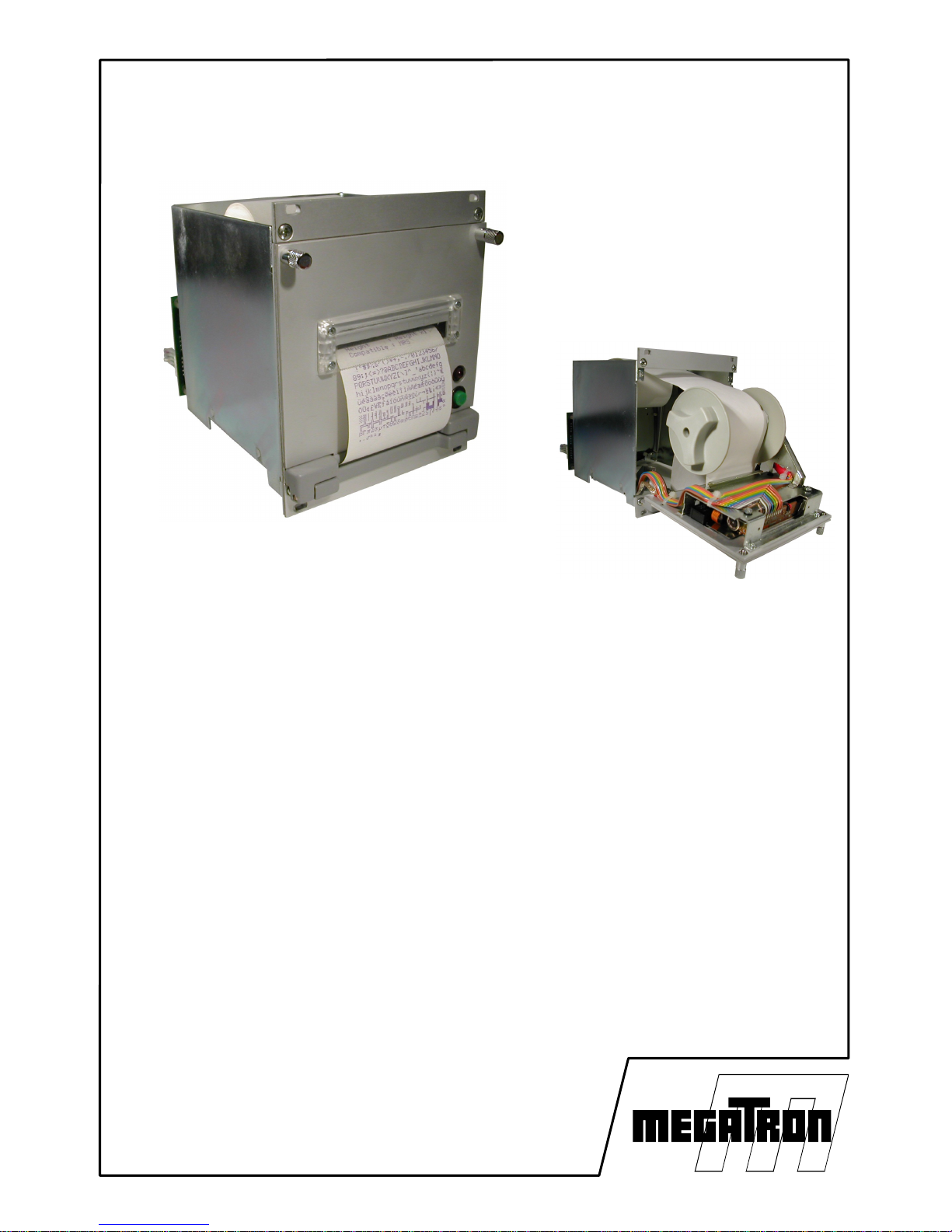
MRSi-x200 & MRTi-x200
3U Metal Box Printer
with paper rewinder
with EPSON dotmatrix
mechanism
• Printing mechanism
• Dot-matrix technology in 144, 192 or 240 dots/line
• 4 or 8 needles shuttle printer
• MRSi: printer with Epson M-160 mechanism
• MRTi: printer with EPSON M-190 mechanism
• Interface
• TTL serial or RS232C from 110 to 19k2 baud
• USB 2.0 Printer Class
• Ethernet
• Power Supply: DC 5 V, DC 9-40 V or Mains
• Characteristics
• 3U Metal Box printer with paper rewinder
• Self-test and hexadecimal dump
• 2 characters fonts
• Graphic curve mode
• Horizontal line graphic mode.
• Real time clock
with summer / winter adjustment
User manual - version 0.3 – English
Page 2

SUMMARY
1 Generality.......................................................................................................3
1.1 Functioning.............................................................................................3
1.2 Material description................................................................................4
1.3 Part number............................................................................................5
1.4 Technical Data........................................................................................6
2 Printer Operation............................................................................................7
2.1 Start-Up..................................................................................................7
2.2 System Reinitialization (RESET)............................................................7
2.3 Self-test or Hexa Dump..........................................................................7
2.4 3U Rack With Paper Rewinder (MRxi-x2xx)..........................................8
2.4.1 Paper End.......................................................................................9
2.4.2 Status Led......................................................................................9
2.4.3 Replacing of the Ink Cartridge:.....................................................10
2.4.4 Replacing the paper :....................................................................11
2.4.5 Fixing............................................................................................12
2.4.6 Size...............................................................................................13
3 Driver installation..........................................................................................14
3.1 Windows...............................................................................................14
4 Wiring Information........................................................................................17
4.1 Board connections................................................................................17
5 Configuration menu......................................................................................18
6 Fonts & Control codes..................................................................................23
6.1 Character Sets......................................................................................23
6.2 Control codes PCL Raw.......................................................................23
6.3 Control codes ESC/P 9 PINS...............................................................24
6.4 Control code ESC/P Basic...................................................................24
6.5 Control code MRS & MP-181...............................................................25
7 Annexe.........................................................................................................26
7.1 Cables and Consumables....................................................................26
MRSi & MRTi – x2xx v0.3 2
Page 3

1 GENERALITY
1.1 FUNCTIONING
Most of the printers available on the market allow printing data, text or graphic
supplied by a computer or a PLC. When designing the MRSi and MRTi
printers, we took into account many special requests from our customers in
order to design the most universal O.E.M printer available today.
Several housings are available in order to integrate these printers on
machine front panel or a 3U equipment
With its dotmatrix technology, this printer is the right solution for tracability
applications, when a long preservation of the ticket is required.
Many features are included in the printer software allowing graphic printing
and a lot of special effects:
Bonus:
● Compatibility: with printer language like Epson ESC/P 9 pins,
HP PCL Raw or Megatron MRS
● 2 character fonts in 6x10 and 10x10 matrix
● Selftest and Hexadecimal dump to debugging the interface
● Windows 2K / XP and Vista 32 driver available on our website
www.megatron.fr.
3 MRSi & MRTi – x2xx v0.3
AGREEMENTS
Because of the evolution of standards and technologies and in
a permanent concern of improvement, the contents of this
manual are subject to change without notice.
Page 4

1.2 MATERIAL DESCRIPTION
The printer is designed around a PSD3434E microprocessor, with 7K-Bytes of
RAM available for buffering datas. An internal watchdog in the microprocessor is
activated to insure an operation in strongly polluted industrial environment.
Printing heads: 2 kinds of head can be used :
- MRSi printers are equipped with Epson M-160 dot-matrix head family with 4
needles allowing slow graphic printings with long delay between lines
- MRTi printers are equipped with Epson M-190 dot-matrix head family with 8
needles allowing fast text or graphic printings
Serial Interface: The printer can be connected in serial in TTL or RS232C levels.
Hardware (RTS/CTS) and software (XON/XOFF) handshakes are simultaneously
supported.
USB 2.0: The printer can be connected in USB 2.0 at full speed. Printer class
(class 7) is supported.
Accessories: Several accessories like Line-Feed button, control LED, paper-end
detector and rewinder are directly managed by MRSi and MRTi printers.
Power Supply: Depending of the model, VCC power supply must be supply in
DC 5 V, DC 9 to 40 V or Mains.
MRSi & MRTi – x2xx v0.3 4
Page 5
1.3 PART NUMBER
Several versions of the electronics and cases are available. To completely define
your product, it is necessary to add a suffix to the name of the printer to specify
the printer type, the selected computer connection, the power supply and the
clock option.
M R x i - x1x2x3x4- x
c
Head Family
Dot-matrix with 4 needles: M-160 : [S]
Dot-matrix with 8 needles: M-190 : [T]
Characters by line
144 dots / line : [2]
192 dots / line : [3]
240 dots / line : [4]
Kind of case
No case : [0]
3U panel case without paper rewinder : [1]
3U panel case with paper rewinder : [2]
Panel mounting case with drawer : [3]
Black plastic case : [4]
Interface
Serial TTL (level 0-5V) : [1]
Serial RS232C (level ±12V) : [2]
USB 2.0 interface : [6]
Ethernet interface : [7]
Power Supply
DC 5 V : [1]
Mains 230 VAC - 50/60 Hz(*) : [2]
DC 9 to 40 V : [3]
Clock option
installed : [C]
not installed : [ ]
(*)
Mains supply is actually under developpment. Any order of a MRxi-xxx2 will
be temporarily delivered with MRxi-xxx1 with a separated Mains Supply.
5 MRSi & MRTi – x2xx v0.3
Page 6
1.4 TECHNICAL DATA
Serial Interface TTL serial
RS232C/V24 serial
Handshake Xon/Xoff and RTS/CTS
USB Interface USB 2.0, Printer Class
Working temperature 0 to 50°C
Power supply (model depending) 5 VDC 9-40VDC 5 VDC 9-40 VDC
Consumption at 5V at 12V at 5V at 12V
Waiting < 0,1A < 0,1A < 0,1A < 0,1A
Average 0,8 A 0,5 A 2,5 A 0,7 A
Peak 1,5 A 1 A 5,5 A 2,3 A
Model MRSi MRSi MRTi MRTi
MRSi MRTi
Print Heads 2xxx 3xxx 4xxx 2xxx 3xxx 4xxx
Reference M-160 M-161 M-162 M-190 M-191 M-192
Dots / line 144 192 240 144 192 240
Text printing speed ~ 0,7 l/s ~ 0,5 l/s ~ 0,4 l/s ~ 2,5 l/s ~ 1,9 l/s ~ 1,5 l/s
MCBF (lines) ~ 500K ~ 500K ~ 500K ~ 1 500K ~ 1 100K ~ 900K
Character Set IBM-II
in matrix 6 x 10 dots (v*h)
MRSi & MRTi
2xxx 3xxx 4xxx
Chars/line 24 32 40
Chars. width (mm) 2,0 1,5 1,2
Chars Height (mm) 2,6 2,6 2,6
Character Set IBM-II
in matrix 10 x 10 dots (v*h)
MRSi & MRTi
2xxx 3xxx 4xxx
Chars/line 14 19 24
Chars. width (mm) 3,3 2,5 2,0
Chars Height (mm) 2,6 2,6 2,6
MRSi & MRTi – x2xx v0.3 6
Page 7
2 PRINTER OPERATION
2.1 START-UP
1. Connect the power supply and connection cables
2. Turn power on
The interface will control its memory, set its parameters according to the data
menu stored in its Flash memory, look for the possible presence of a clock
circuit and moves the printing head for one line to determine the dot number
of the connected head. At the end of this initialization cycle, the printer is
ready for receiving characters.
2.2 SYSTEM REINITIALIZATION (RESET)
The printer is designed with a watchdog which makes a reset at power-up
authorizing the use of a slow ascent supply. About 300 milli-seconds after the
controller is powered-up, this one is ready for operation, having ended its
reset cycle.
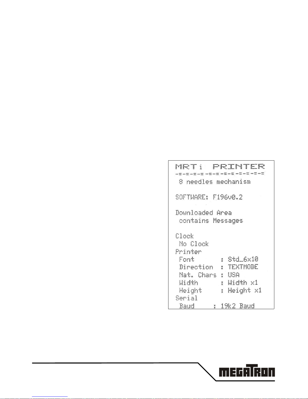
2.3 SELF-TEST OR HEXA DUMP
If, after a reset or at power-up, the linefeed
button is maintained pushed, a self-test
cycle is run. The printer prints its name.
At this time if you :
● continue pressing the LF button,
the hexadecimal dump mode is
invoked. A message 'DUMP HEXA
MODE' is printed. Release the LF
button. Now the value of all the
received data will be printed in
Hexadecimal followed by their
ASCII value if printable. Power-off
the printer to leave this mode.
● release the LF button, all the
parameter settings and the
character set are printed. At the end
of the self-test the printer will work
normally.
The self-test gives only a probability of correct operation of the printer; indeed,
the self-test procedure does not use transmission, this one can only be tested
in real mode.
7 MRSi & MRTi – x2xx v0.3
Page 8
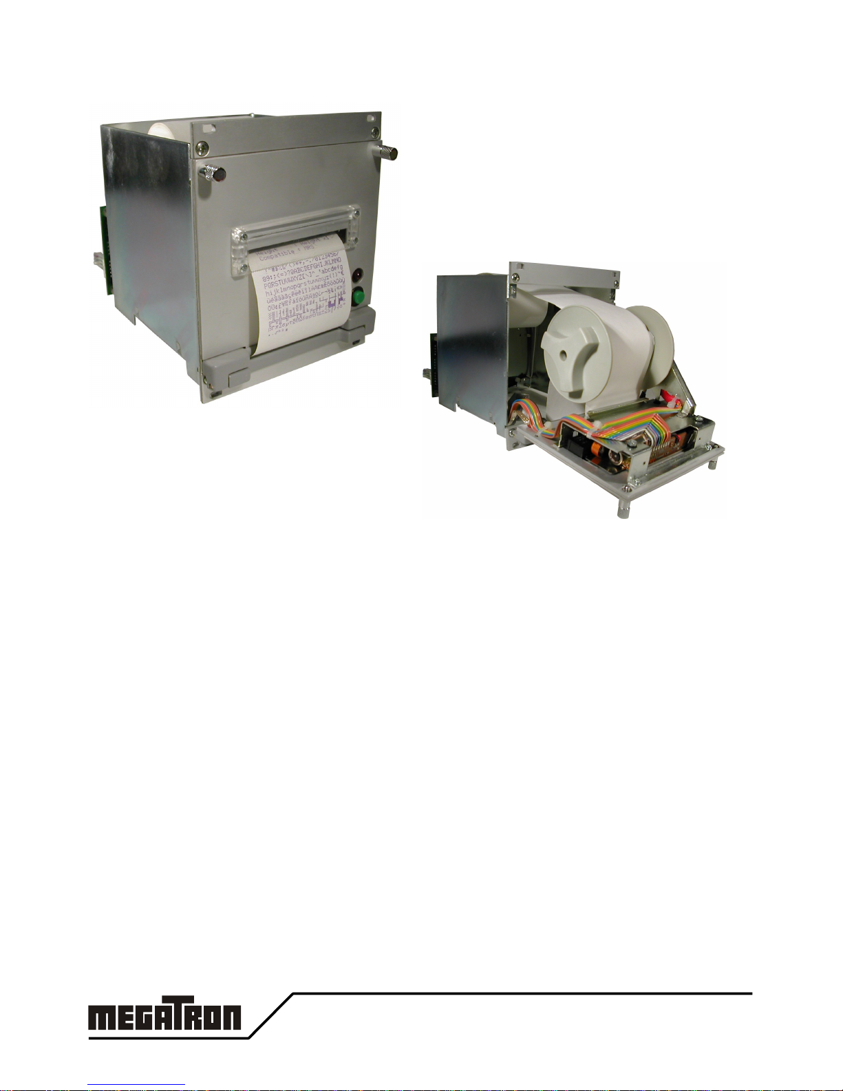
2.4 3U RACK WITH PAPER REWINDER (MRXI-X2XX)
This case is a small mono-block case
integrating a printing head, a paper roll
support and a paper rewinder.
This case is compatible with the EURODIN
standard and can be directly installed in a
3U system rack.
The interface is fixed at the back of the
case making an autonomous and
compact product. The front door can be
opened to give access to the paper roll.
The ink cartridge can be changed by
removing the first part of the door.
The dimensions of this printer are identical to those of the previous printer.
The same printer exists without a paper rewinder. For more information about
this product, refer to MRSi-x1xx and MRTi-x1xx documentation.
MRSi & MRTi – x2xx v0.3 8
Page 9
2.4.1 Paper End
If a paper-end occurs, the red LED will blink
and the printout is hanging.
Depending of the « No Paper » menu setting,
the paper defect can :
● be totally ignored (ignored)
● stop the printout but can accept the
data until the buffer is full (Fill Buff.)
● stop the printout and stop the data
transmission (Set Busy)
2.4.2 Status Led
A status LED informs the user of the possible defects of operation.
When this led is out, it indicates a correct operation, a blinking LED indicates
an abnormal status which is explained in the table below:
LED Cycle Description System
Ä
l l l l l l l l l l l l l l l l
Å Correct operation No
Ä
l¡l¡l¡l¡l¡l¡l¡ l ¡
Å
Paper End No
Ä
l l l l l l l l l ¡l ¡ l ¡l ¡
Å Printing head defect Yes
Ä
l l l l l l l l l ¡l ¡ l l l l
Å
RAM memory defect Yes
Ä
l l l l l l l l l ¡l l l l l l
Å Menu activated Yes
LED period : 80 msec .
The user can drive directly the red LED with the software command.
But the 'system' status is priority and can't be inhibited.
9 MRSi & MRTi – x2xx v0.3
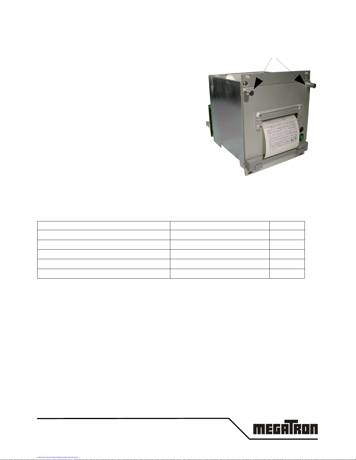
To open the case,
unscrew these two screws
below
Page 10

2.4.3 Replacing of the Ink Cartridge:
1. Tear off the rewinded paper .
2. Unscrew the two unremovable screws (1 and 2). The panel ( 3 ), in front
of the revolving door, can then be removed giving access to the ink
cartridge ( 4 ).
3. On the left part of the ink cartridge( 4 ) is a marked carving " PUSH ";
press on this carving, the ink cartridge lifts up itself then take it off.
4. Insert a new cartridge by watching if the paper goes between the ink band
and the body of the cartridge. Position the cartridge so that the button of
tension of the ribbon is in front of its spur of training. Press on the two
extremities of the cartridge which go in the right position and a light click
sound indicates that it is correctly set.
5. Pull about 20 cm of paper towards the outside thanks to the paper feed
button (if the printer is not under power, it is possible to pull the paper by
hand under the condition of not pulling it too fast).
6. Put back the panel ( 3 ) having made the paper cross through the
plexiglas window ( 5 ). Plug the low part of the panel at the top of the door
hinge (6) then stick it to the revolving door.
7. Put the two unremovable screws (1 and 2) in the revolving door without
screwing them
8. Open then the revolving door ( 7 ) of the printer which gives access to the
paper rewinder ( 10 ). Remove the freezing fork of the paper rewinder by
pulling it to the left. Then remove all the rewinded paper from the paper
rewinder.
9. Place the extremity of the paper against the central pit of the rewinder
( 10 ) and block it with the blocking fork.
10. Close the revolving door ( 7 ) and completely screw the two unremovable
screws (1 and 2)
MRSi & MRTi – x2xx v0.3 10
Page 11

2.4.4 Replacing the paper :
1. Tear off the rewinded paper first.
2. Unscrew the two unremovable screws (1 and 2). The panel ( 3 ), in front
of the revolving door, can then be removed.
3. Open the revolving door ( 7 ) giving access inside the printer.
4. Tear the paper coming from the paper roll ( 8 ). For a moment close the
revolving door and remove the paper staying in the printing head.
5. Remove the old paper roll and its paper axis from the paper holder.
6. Make a frank cut at the end of the new paper roll, but do not install it on
the support (printing would start immediately). The strip of paper must
hang forward to the roll. Insert the extremity of the paper between the two
lips of the printing head ( 9): the first lip is in plastic and the second is in
metal.
Put the strip of paper between the paper rewinder ( 10 ) and the back of
the printing head ( 11 ).
7. Make a paper advance while maintaining engaged the paper.
8. Introduce the paper axis into the new roll. Insert both into the paper
holder.
9. Then follow the procedure " REPLACING OF THE INK CARTRIDGE"
from step 5..
11 MRSi & MRTi – x2xx v0.3
Page 12

2.4.5 Fixing
MRxi-x2xx case fits directly in a 3U rack system or can be accommodated in
a panel where a window was cut. 4 elongated holes in the front panel allow
for an easy mounting of the printer.
The printer MRxi-x2xx can be directly embedded in a panel where a window
(106.5 x 115 mm) and 4 x M3.2 holes were practiced.
Introduce the case by the front of the panel.
Screw the four fixation screws until obtain a freezing mechanics of the case
against the panel.
MRSi & MRTi – x2xx v0.3 12
Page 13

2.4.6 Size
Designation Width Height Depth D Supply
Case alone 106.5 mm 129 mm 113 mm None
MRxi-x2x1 cases 106.5 mm 129 mm 150 mm 5 VDC
MRxi-x2x3 cases 106.5 mm 129 mm 150 mm 9 to 40 VDC
(*)
Mains supply is actually under developpment. Any order of a MRxi-xxx2 will
be temporarily delivered with MRxi-xxx1 with a separated Mains Supply.
13 MRSi & MRTi – x2xx v0.3
Page 14

3 DRIVER INSTALLATION
3.1 WINDOWS
A windows driver for Windows 2000, XP, Vista32 is available on your website.
● Unzip it on a folder then connect the printer to your computer.
Printer name used in the driver is the beginning of the printer
reference; e.g.: MRSi-2, MRSi-3, MRSi-4, MRTi-2, MRTi-3, MRTi-4
● Add new printer and set the driver path with the folder parth
● After installation, set the driver properties accordingly to your
requirements.
● Paper Size: Roll 58x82 mm, Roll 58x150 mm, Roll 58x210 mm
● protocole: ESC/P 9pins, ESC/P Basic, PCL Raw
● In the windows applications, set the paper size to 5,8 cm width with
left and right margins at 0,5 cm.
No Top and bottom margins are necessary.
MRSi & MRTi – x2xx v0.3 14
Page 15

Serial:
the printer is not automatically detected.
● click on "add new printer" in the
Printer and Fax folder.
● Select a local Printer
● In the 'Select Printer Port"
window,
select the right serial Port
(Com1.. ComX)
● Then continue to install the printer
driver as usual
● When the installation is finished, you
must set the settings of the serial port
accordingly with the printer in the the
printer driver properties : Baud rate,
Data Bits, Parity, Stop bits, Flow
Control.
Don't forget to set the Flow Control to Hardware or Xon/Xoff
USB:
When you connect an USB printer to windows (2K/XP/Vista32), the OS
automatically detect it ans will ask you to install the correct driver.
15 MRSi & MRTi – x2xx v0.3
Page 16

Ethernet: Driver installation is usual except that you need to install a new port
on your computer.
● In the printer and Fax window, click on "add new printer".
● Select a local Printer
● In the 'Select Printer Port" window, select "Create a new port"
and choose "Standard TCP/IP Port"
● In the "Add Port" Window, fill "IP address" with the address
you find previously in the Lantronic Device Installer or you
fixed in chapter " Change Module Settings". A name is
automatically filled, you can change it if you want.
● In the "More Port Information are necessary", select
"Standard: Generic Network Card"
● Then continue to install the printer driver as usual
MRSi & MRTi – x2xx v0.3 16
Page 17

4 WIRING INFORMATION
4.1 BOARD CONNECTIONS
Fast connections
POWER
MRxi-xxx1 Connect the DC 5V power supply in J10 or J12
MRxi-xxx2 Plug the secondary of the Mains power supply adapter in
J10 or J12
MRxi-xxx3 Connect the DC 9 to 40V power supply in J10 or J12
Associated connector: Miniconnec MC 1,5/2-ST-3,81 from Phoenix-Contact.
INTERFACE
MRxi-xx1x Connect TTL serial interface in J6
all signals must be in TTL level (0 to 5V).
MRxi-xx2x Connect RS232 serial interface in J6
all signals must be in RS232 level (-12 to +12V).
Maxi-xx6x Connect USB 2.0 interface in J11 (mini-USB B)
This interface is a "Printer Class" (class 7)
MRxi-xx7x Connect Ethernet interface in J13 (RJ-45)
Set Serial parameters with the configuration menu.
No parameters are necessary for the USB interface.
17 MRSi & MRTi – x2xx v0.3
USB Ethernet POWER
J11 or J7 J13 J12, J10
Serial
J6
Panel
J4 or
J3
J9: 8 needles printer M-190 J2
J8: 4 needles printer M-160
Page 18

5 CONFIGURATION MENU
Two different ways are available to configure the printer:
• by the interface (see command esc ])
• by a printed configuration menu.
Here is described the printed configuration menu.
All the navigation in the Menu is made thanks to the LF push button.
Long push on the button is written <<LF>> and short push is written >LF<.
To indicate several short pushes, >LF< is followed by the quantity: >LF x2<
Activation: To activate the Configuration Menu, shortly press 4 times the
Paper Feed button ( >LF x2< ). A 'MENU ACTIVATED' message is then
printed and the first group of configuration items are printed too..
Navigation: In order to modify the settings the following steps have to be
followed:
• navigate through the groups (1)
• navigate through the different items of the group (2)
• modify the value of the items (3)
Timeout: To avoid lock of the printer in the configuration Menu, if no actions
are made on the LF push-button during 15 seconds, the Menu is aborted.
All changes are lost and a 'MENU TIMEOUT' message is then printed.
The printer can accept new data from the interface...
MRSi & MRTi – x2xx v0.3 18
Page 19

(1) Navigate through the groups:
<<LF>> A long push on the LF button enters in the different items of
the selected group (2).
First Item is then printed...
>LF x1< One short push on the LF button displays the next group.
New group is then printed...
>LF x2< Two short pushes on the LF button display the previous
group. New group is then printed...
>LF x3< Three short pushes on the LF button save the modifications
and exit the configuration mode.
The message ‘MENU EXITED’ is printed out and a reset of
the printer is then performed.
(2) Navigate through the items of a group:
<<LF>> A long push on the LF button enters in the different values
of the selected item (3).
>LF x1< One short push on the LF button displays the next item.
New item and its associated value is then printed...
>LF x2< Two short pushes on the LF button display the previous
item. New item and its associated value is then printed...
>LF x3< Three short pushes on the LF button exit the navigation in
the items and come back in the group navigation level (1).
(3) Modify the value of an item:
<<LF>> A long push on the LF button validates the new selected
parameter and prints this value in double width for control
purpose. If the value is a clock item, the clock chip is
immediately updated. For other items, the configuration menu
has to be exited before the values are effective.
>LF x1< One short push on the LF button displays the next value.
See note on the >LF x2<
>LF x2< Two short pushes on the LF button display the previous
value. Note: The new selected value is only printed after a
certain inactive time thus allowing multiple short presses
without printing. This works only for multiple pushes higher
than three, because >LF x2< and >LF x3< are used for
navigation purpose.
>LF x3< Three short pushes on the LF button exit the navigation in
the values and come back in the item navigation level (2).
19 MRSi & MRTi – x2xx v0.3
Page 20

Menu Summary Table
Groups Fields Values
Clock Hours 00 - 23
Minutes 00 - 59
Days 00 - 31
Months 01 - 12
Year 00 - 99
Printer 1: Font Std_6x10 (Font 1), Std10x10 (Font 2)
2: Direction TEXTMODE, DATAMODE
3: Nat. Chars USA, FRA, GER, ENG, DK1, SWE,
ITA, SPA, JAP, NOR, DK2, NDL
4: Width Width x1, Width x2
5: Height Height x1, Height x2
6: PageLength 0..255
7: Tab Length
8: Gr.Hor_Res No zoom, Zoom x1, Zoom x2
9: Print Case
A: PCL HScale 1..255
Group #2 B: PCL VScale 1..255
Serial 1: Baud 110, 150, 300, 600, 1200,
2400, 4800, 9600, 19k2
2: Databits 7 databits, 8 databits
3: Parity No, Even, Odd parity
Group #3 4: Xon Single Xon, Repeat Xon
Advanced 1: Compatible ESC/P 9pin, ESC/P Base, PCL Raw,
Hexa, MRS, MP181
2: No Paper Fill Buff., Set Busy, Ignored, Warn Host
3: Winter/Sum Disabled, Enabled
4: Add curve No EXT, EXT 0, EXT 1, Both EXT
5: External Both CPT, ADC0-CPT1, CPT0-ADC1, Both
ADC
6: Info Stamp No Stamp, Add Date, Add Logo
7: Bin. Pins Separated, Multiplex
Group # 4 8: Bin. Init Power Val, All Open
Timer 1: Timer Use Disabled, Enabled
2: Timer Second 0..59 seconds
3: Timer Minute 0..59 minutes
4: Timer Hour 0..12 hours
Group #5 5: Alt. Print 0..255
MRSi & MRTi – x2xx v0.3 20
Page 21

SHORT PARAMETERS EXPLANATION:
● Set Clock: Clock setting mode.
● Printer: Change printing parameters
● Font: Default character fonts (between the 2 proposed fonts)
● Direction: Default choice of the orientation: text or data
● Nat. Chars. Select default national characters.
This choice is useful with 7 bits communication.
● Width: Select default character width.
● Height: Select default character height.
● Serial: Change serial parameters
● Baud: Communication baudrate from 110 baud to 19k2 baud
● Databits: Number of databits (7 or 8)
● Parity: Parity kind: Even, Odd or None
● Xon: Number of XON sended in XON / Xoff protocol
before reception of the first character
- Single XON (a single XON is transmitted)
- Repeat XON (a XON is transmitted every 300 msecs)
● N.B.: Hardware handshaking (RTS/CTS) is always enabled.
● Advanced : Change advanced parameters
● Compatible: Interpretation of successful data e.g software
compatibility ESC/P 9Pin (standard), ESC/P Base, PCL Raw, MRS ou
MP181
● Paper end: User information in case of paper defect :
● 'Set Busy': the printer blocks the connection immediately
● 'Fill Buff.': the buffer continues to be filled and the user will be
warned when the buffer is full
● 'Ignored': a paper defect is ignored, the printout continues
● 'Warn Host': the user will be warned but the printout continues
Notes:
Paper defect: 'Set Busy', 'Fill Buff.' and 'Warn Host' modes warn the host
by sending the character EM (19h). When the paper is present, the printer
send character ETB (17h)
Head defect: Each mode warns the host by sending the character DC2
(18h), followed by the busy signal (RTS=BUSY and send of XOFF).
To correct it, check the head mechanism and push several times the
linefeed button to reactivate the head. When it works again, the printer send
the character (16h) and the busy condition is removed (send of XON and
RTS=FREE).
When head defects occur, you must contact the repair service.
● Winter/Sum: Activation or not of the automatic change
21 MRSi & MRTi – x2xx v0.3
Page 22

between winter and summer time.
● Add Curve: Select which analogical or counting entries EXT0 and/or
EXT1 will be automatically added to the graphic curves.
● External: Use of the entries EXT0 and EXT1
- like analogical to digital (ADC) entries or
- like counting entries (CPT)
● Info Stamp: Automatically add of information after text paragraphs
- No Stamp: No additional information
- Add Date: Date stamping (Date & time is added)
- Add Logo: Logo is added (personal message)
● Bin. Pins: Select the management of the 4 binary entries :
- Separated or Multiplexed.
● Bin. Init: Initial values of the 4 binary entries at power on :
- "Power Val", read the initial value of each bit
- "All Open" , initial value is 1 for each bit (open)
● Timer : printing timer for logo or messages #15 and #14.
● Timer Use : Activate or not the timer at power on
● Timer Second: Set the timer period in seconds (range 0.. 59 seconds)
● Timer Minute: Set the timer period in minutes (range 0.. 59 minutes)
● Timer Hour: Set the timer period in hours (range 0.. 12 hours)
Warning: if the period is set to 0, timer is disabled.
● Alt Print: Cyclic ratio between printing of messages #15 and #14.
If n>0, timer starts n times the printing of message #15
then only one time the printing of message #14.
MRSi & MRTi – x2xx v0.3 22
Page 23

6 FONTS & CONTROL CODES
6.1 CHARACTER SETS
Two complete sets of 255 IBM-II characters are available in ROM as well as
national characters. Characters exist in 6x10 and 10x10 matrix with uppercase
and lowercase letters.
The selection of national characters is done by software or by the configuration
menu.
6.2 CONTROL CODES PCL RAW
The compatibility PCL Raw has been implemented in order to allow the printer
to work with computers. Only the graphic functions are implemented. The
other control codes are ignored. The compression algorithms Run Length and
Tiff are supported. Delta Row will be available as soon as possible.
Mnenonics Hex PCL codes available
ESC "&" 1B 26
ESC "&" a # H Horizontal position
ESC "*" 1B 2A
ESC "*" b # W Graphics printing
ESC "*" b # M Selection of compression algorithm :
without compression, Run Length, Tiff, Delta Row
ESC "*" r # T Page length
ESC "*" p # X Page width
ESC "E" 1B 45 Soft reset
23 MRSi & MRTi – x2xx v0.3
Font: Standard 6 x 10
Font: Standard 10 x 10
Page 24

6.3 CONTROL CODES ESC/P 9 PINS
The compatibility ESC/P 9 PINS has been implemented in order to allow the
printer to works with computers. Only the graphic functions are implemented.
The other control codes are ignored. The codes implemented are shown with
a mark in the column ‘9 Pin’ of the table.
6.4 CONTROL CODE ESC/P BASIC
These codes are less compatible with ESC/P, but they give some functions
more specific to the printer. Most of these codes work same way as 9 pins.
Attention, Major difference in graphic:
The graphic modes are very similar, but the function of the CR at the end of
the graphic is different :
• for ESC/P Basic, the code CR makes a line feed like a LF code.
• for ESC/P 9 pins, the code CR makes only a carriage return without any
line feed.
The characters with their ASCII values between 01 hex and 1F hex are
control characters and are not printable. These characters allow to modify the
behaviour of the interface (control characters). .
Mnemo Hex Control codes Basic 9 Pins
HT 09 Tabulation x x
LF 0A Line feed x x
FF 0C Page feed x x
CR 0D Carriage return x x
SO 0E Double width x x
DC4 14 Normal width x x
ESC "!" 1B 21 Master mode x
ESC "$" 1B 24 Horizontal position: nL nH x
ESC "'" 1B 27 Graphic Printing x
ESC ")" 1B 29 Advance of n lines of characters x x
ESC "*" 1B 2A Graphic Printing : 8 points per column
(ESC "*" 0, ESC "*" 1, ESC "*" 2 or ESC "*" 3)
x x
ESC "-" 1B 2D Underscore ON:OFF x x
ESC "2" 1B 32 Sets interlining to 0 x x
ESC "3" 1B 33 Sets interlining to n x x
ESC "@" 1B 40 Soft reset x x
ESC "C" 1B 43 Page length x x
ESC "D" 1B 44 Sets tabulations x x
ESC "F" 1B 46 Font selection x
ESC "J" 1B 4A Advance of n lines of dots x x
ESC "K" 1B 4B Graphic Printing : 8 dots/columns x x
ESC "L" 1B 4C Graphic Printing : 8 dots/columns x x
ESC "M" 1B 4D Selection of the font 1 (6x10) x
ESC "P" 1B 50 Selection of the font 2 (10x10) x
MRSi & MRTi – x2xx v0.3 24
Page 25

Mnemo Hex Control codes Basic 9 Pins
ESC "R" 1B 52 Selection of national characters x x
ESC "S" 1B 53 Control of status DEL x
ESC "V" 1B 56 Synchronisation character (RS232 only) x
ESC "W" 1B 57 Character widening x x
ESC "Y" 1B 59 Graphic Printing : 8 dots/columns x x
ESC "Z" 1B 5A Graphic Printing : 8 dots/columns x x
ESC "a" 1B 61 Selection of the alignment x x
ESC "c" 1B 63 Date stamping & clock setting x
ESC "f" 1B 66 Printing of 1 line of dots x
ESC "g" 1B 67 Selection of the font 1 (6x10) x
ESC "j" 1B 6A Prints but do not go back x
ESC "t" 1B 74 Selection of the table of the characters codes x
ESC "x" 1B 78 Selects the printing NLQ or Draft x
ESC "w" 1B 77 Elongation of the characters x x
ESC "{" 1B 7B Selection of the direction of the printout : Text or Data x x
GS "V" 1D 56 Advances to the cutting bar, then n/2 lines of dots x
GS "[" 1D 5B Switch acquisition (RS232 only) x
GS "]" 1D 5E Configuration of the switches x
GS "^" 1D 5E Activation of the timer x
GS "c" 1D 63 Date stamping & clock setting x
GS "m" 1D 6D Printing of a pre-stored message x
GS "p" 1D 70 Printing of the logo x
GS "s" 1D 73 Programmation of the messages & logo x
GS "u" 1D 75 Transmission of data trough the serial. (RS232 only) x
GS "v" 1D 76
Return of data towards the emitter. (RS232 only) x
6.5 CONTROL CODE MRS & MP-181
The compatibility MRS and MP-181 has been implemented in order to allow
direct replacement of the older printers: MRS ans MP-181.
25 MRSi & MRTi – x2xx v0.3
Mnemo Hex Control codes
SOH 01 ASCII character set
STX 02 Graphic bar
EOT 04 French character set
ACK 06 Graphic bar pattern
BEL 07 Clock (set or display)
TAB 09 Tabulation
LF 0A Line feed
FF 0C White line
CR 0D Carriage return
Mnemo Hex Control codes
SO 0E Double width
SI 0F Text mode
DLE 10 Data mode
DC3 13 Special characters
DC4 14 Single width
SYN 16 Black line
ETB 17 Feed n lines
SUB 1B Cut paper
ESC 1B Register mode
Page 26

7 ANNEXE
7.1 CABLES AND CONSUMABLES
Part number Description
DKM-242-V Serial cable RS232C/V24
• HE10-2x5 pins / Sub-D9-F
• Length mini 1m50
MPA-NO-58-50-1 White Paper Roll
• Width 58 mm ± 0,5 mm
• External diameter 50 mm
• Length 20 m ± 10%
MPA-NO-58-50-2 Duplicating White Paper Roll
• 2 sheetsWidth 58 mm ± 0,5 mm
• External diameter 50 mm
• Length 17 m ± 10%
MPA-SP-58-46-1 Self-revelant White Paper Roll (micro-bubbled)
(ink cartridge unnecessary)
• Width 58 mm ± 0,5 mm
• External diameter 46 mm
• Length 17 m ± 10%
MDE-250-N Black Ink cartridge
• Life length about 100 000 characters
MDE-250-V Purple Ink cartridge
• Life length about 100 000 characters
MRSi & MRTi – x2xx v0.3 26
Page 27

27 MRSi & MRTi – x2xx v0.3
Page 28

Potentiomètres de précision
Résistances de précision
Servo-Systèmes
Capteurs
Interfaçage
Systèmes d'impression
Claviers
Techniques d'affichage
Centre de production
et Bureaux Commerciaux
MEGATRON
Z.I. de Noyer
B.P. 1
F- 74200 ALLINGES
Tél: +33 (0) 4.50.70.54.54 - Fax: +33 (0) 4.50.70.56.56
Internet: http://www.megatron.fr - E-mail: info@megatron.fr
 Loading...