

Page 1
Programming Manual ETA25PS
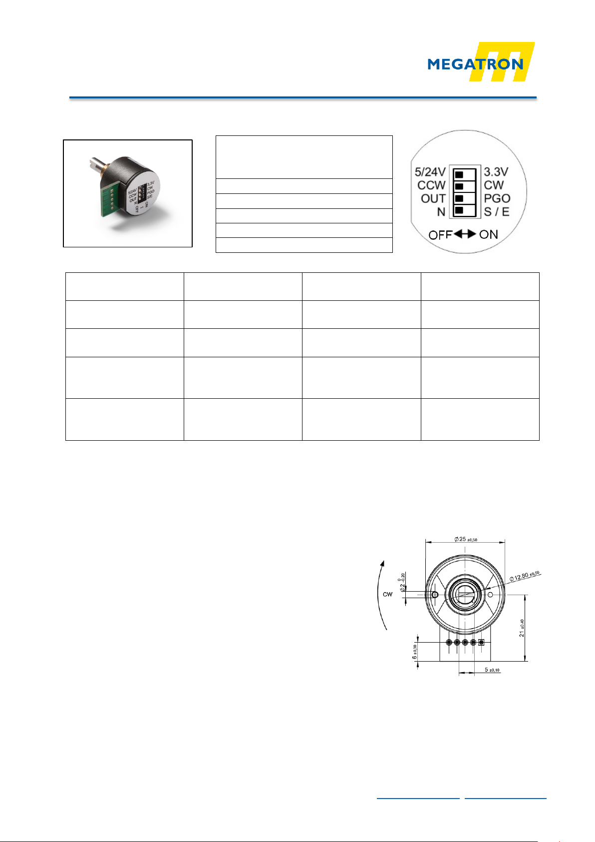
Function Switch No.
DIP-Switch OFF
DIP-Switch ON
Supply voltage 1
5V (24V *)
3.3V
Sense of rotation
2 CCW
CW
Operating mode
3 OUT
PGO
Programming input
4 N
S / E
Pin-Assignment:
1 = VSUP
2 = OUT
3 = GND
4 = SCL
5 = SDA
1 z 2
MEGATRON, s.r.o. Mrštíkova 16, 100 00 Praha 10, T.: +420 274 780972, info@megatron.cz, www.megatron.cz
Operation of the Programming Interface ETA25PS
Solder lugs, 5-PIN, Contact
Spacing 2,54mm
Programming Procedure:
A. Before you connect the supply voltage:
1. Configure DIP-Switc h 1: Chose supply Voltage (5V (24V / 3.3V)). (*) In case that 24V supply
voltage version was ordered it is not allowed to switch DIP switch 1 to 3.3V position.
2. Configure DIP-Switc h 2: Chose sense of rotation (rising output signal in CW or CCW direction
please see drawing on the right hand)
3. DIP-Switches 3 and 4 must be set both in OFF-Position
B. Program m ing the start- and end position:
1. Connect power supp l y voltage
2. Switch DIP-Switch 3 to ON-Position (programming mode)
3. Put the shaft to start position and set DIP-Switch 4 for > 1s to ON and then back to OFF
4. Put the shaft to the end position and set DIP-Switch 4 for > 1s to ON and then back to OFF
5. Switch DIP-Switch 3 to OFF-Position (measuring mode)
READY
(measuring mode)
(inactive)
(programming mode)
(setting start / end
position)
Page 2

Programming Manual ETA25PS
2 z 2
MEGATRON, s.r.o. Mrštíkova 16, 100 00 Praha 10, T.: +420 274 780972, info@megatron.cz, www.megatron.cz
Please note:
-
- The change of the sense of rotation (CW / CCW) and the supply voltage (5V / 3.3V) can be
- The programming switches 3 and 4 are out of function after programming.
The adjustment of the start- and end position by means of the DIP-Switch programming
procedure can be proceed only once (OTP).
changed several times (<500x).
 Loading...