

MegaTech Solar Installation Manual
1
tech
36 00 5823 Issue 4
tech
Fitting and using the Megatech Solar unvented
mains pressure water heater
Solar
36005942 issue 4

2
2
techtech
Contents
SECTION PAGE
1 INTRODUCTION ...........................................................................3
2 GENERAL REQUIREMENTS ...................................................... 4
3 INSTALLATION - GENERAL ......................................................... 6
4 INSTALLATION - SOLAR PRIMARY ............................................ 15
5 INSTALLATION - DIRECT UNITS ................................................. 16
6 INSTALLATION - AUXILLARY COIL (INDIRECT UNITS) ............ 18
7 COMMISSIONING ....................................................................... 23
8 USER INSTRUCTIONS................................................................ 25
9 MAINTENANCE ...........................................................................27
10 FAULT FINDING & SERVICING .................................................. 29
11 DIMENSIONS & SPECIFICATIONS ........................................... 32
12 GUARANTEE ................................................................................ 35
13 CONTACTS ................................................................................... 36
Contents
Please read and understand these instructions before starting work.
The information contained in these instructions details how to connect
the Megatech Solar water heater to a solar primary circuit. Other
controls will be necessary to provide control over the primary circuit,
refer to the instructions supplied with the solar controls and ancillary
equipment for details of how to integrate them with the Megatech Solar
unit.
Please leave this leaflet with the user following installation
3
tech
1
Congratulations on your purchase of a Heatrae Sadia Megatech Solar unvented water
heater. The Megatech is manufactured in the UK from top quality materials and meets all
the latest relevant safety and constructional standards. The high grade Duplex stainless
steel cylinder offers exceptional strength and corrosion resistance which is backed by a 25
year guarantee. Its performance and insulation levels exceed the latest requirements of
Building Regulation Part L.
The Megatech unvented water heater can be fed directly from thecold water mains supply
to the property without the need for separate feed cisterns or vent pipes. It is supplied
complete with all the necessary inlet and safety controls, electric immersion heater(s) and,
for units fitted with an auxiliary heating coil, a cylinder thermostat, thermal cut-out , 2-port
motorised valve and wiring centre.
Generally its pressure and flowrate performance will far exceed that from a comparable
vented system, thermal store, multipoint instantaneous gas heater or combination boiler.
Introduction
Introduction
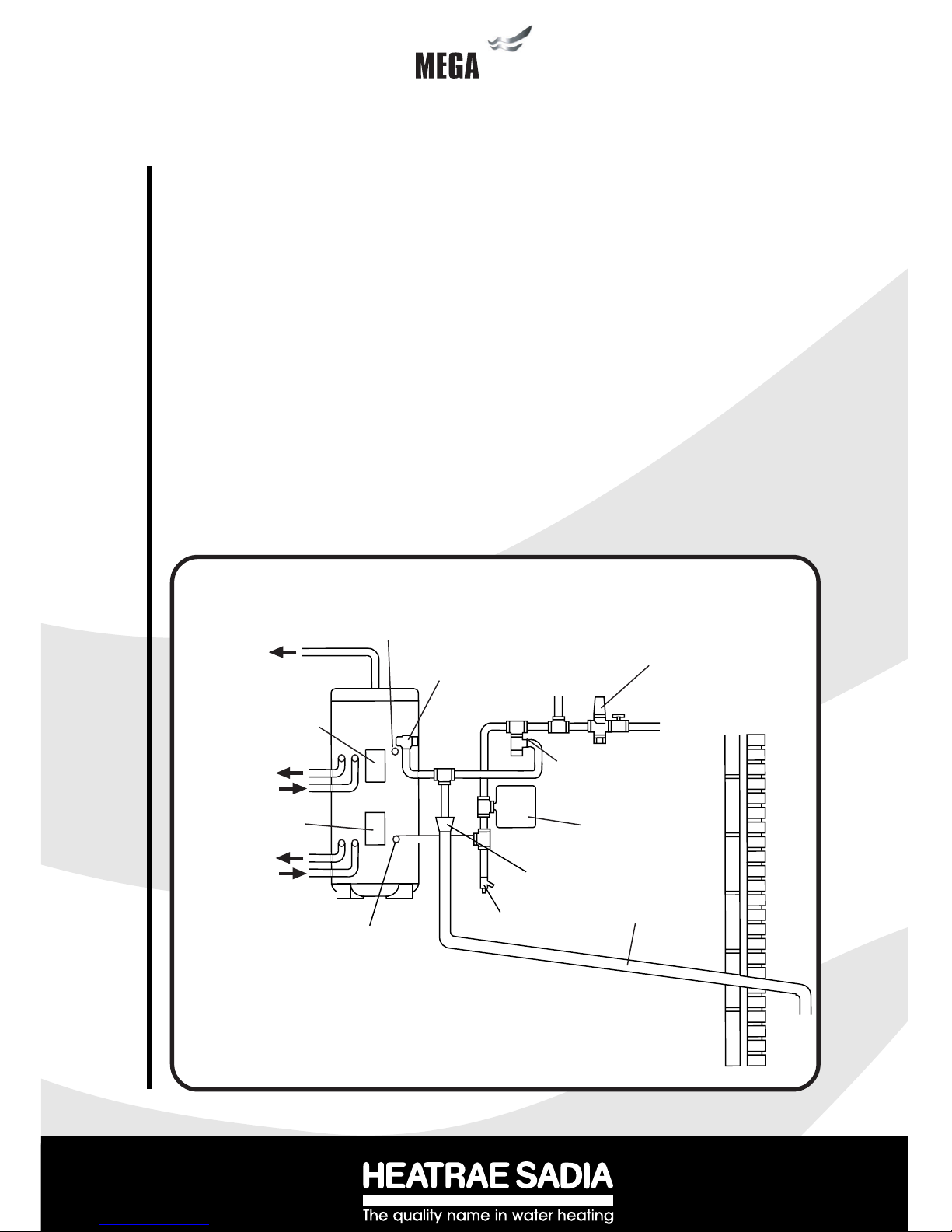
Diagram 1 - Schematic installation details
COLD WATER
COMBINATION
VALV E
BALANCED
COLD WATER
CONNECTION
(IF REQUIRED)
T&P RELIEF
VALV E
AUXILIARY
CONTROLS
HOUSING
AUXILIARY
PRIMARY RETURN
SOLAR PRIMARY
FLOW
INLET
DRAIN COCK
DISCHARGE
PIPE
TUNDISH
SECONDARY RETURN
TAPPING (IF REQUIRED)
TO HOT
OUTLETS
MAINS
WATER
SUPPLY
EXPANSION VALVE
CORE UNIT (SEE
NOTE BELOW)
NOTE: FOR BALANCED PRESSURE COLD WATER SUPPLIES TEE OFF BETWEEN THE COLD
WATER COMBINATION VALVE AND THE EXPANSION VALVE CORE UNIT.
SOLAR PRIMARY
RETURN
AUXILIARY
PRIMARY FLOW
SOLAR CONTROLS
HOUSING
EXPANSION
VESSEL

4
4
techtech
IMPORTANT : PLEASE READ AND UNDERSTAND THESE INSTRUCTIONS BEFORE INSTALLING
THE MEGATECH WATER HEATER. INCORRECT INSTALLATION MAY INVALIDATE GUARANTEE.
THIS APPLIANCE IS NOT INTENDED FOR USE BY PERSONS (INCLUDING CHILDREN) WITH
REDUCED PHYSICAL, SENSORY OR MENTAL CAPABILITIES, OR LACK OF KNOWLEDGE AND
EXPERIENCE, UNLESS THEY HAVE BEEN GIVEN SUPERVISION OR INSTRUCTION CONCERNING
THE USE OF THE APPLIANCE BY A PERSON RESPONSIBLE FOR THEIR SAFETY.
THE MEGATECH SOLAR MUST BE INSTALLED (SECTIONS 2 - 6), COMMISSIONED (SECTION 7)
AND MAINTAINED (SECTIONS 9 - 10) BY A COMPETENT INSTALLER IN ACCORDANCE WITH
BUILDING REGULATION G3 (ENGLAND AND WALES), TECHNICAL STANDARD P3 (SCOTLAND)
OR BUILDING REGULATION P5 (NORTHERN IRELAND) AND THE WATER FITTING REGULATIONS
(ENGLAND AND WALES) OR WATER BYELAWS (SCOTLAND). FOLLOWING INSTALLATION AND
COMMISSIONING, THE OPERATION OF THE HEATER SHOULD BE EXPLAINED TO THE USER
(SECTION 8) AND THESE INSTRUCTIONS LEFT WITH THEM FOR FUTURE REFERENCE.
2.1 COMPONENT CHECK LIST
Before commencing installation check that all the components for your Megatech Solar unit are
contained in the package. The following components are supplied as standard with your Megatech
unit :
• Factory fitted immersion heater (s) and thermal controls
• Cold Water Combination Valve (comprises Isolating Valve, Pressure Reducing Valve,
Strainer, and Check Valve).
• Expansion Core Unit (comprises Check Valve and Expansion Valve)
• Expansion Vessel (including wall mounting bracket)
• Factory fitted Temperature/Pressure Relief Valve (set at 90oC/10bar)
• T&P Relief Valve Insulation Set
• Drain Valve
• Wiring Centre (CL units only)
• Tundish (included in the Cold Water Combination Valve pack)
• Factory fitted Auxiliary heating coil Thermostat and Thermal Cut-out (CL units only)
• 2-port Motorised Valve (CL units only)
• Lifting handle
2.2 SITING THE MEGATECH SOLAR (see Diagram 1)
The Megatech Solar unit must be vertically floor mounted. It can be placed anywhere convenient
provided the discharge pipe(s) from its safety valves can be correctly installed. Areas that are
subject to freezing must be avoided. Ensure that the floor is of sufficient strength to support the “full”
weight of the unit (refer to Tables 4 and 5 on page 33 for unit weights). Pipe runs should be kept as
short as possible for maximum economy. Access to associated controls, immersion heaters and
controls housings should be possible for servicing and maintenance of the system (Note: controls
housings hinge open to the left hand side).
Please do not install valves or pipework (except discharge pipe) within 50mm (2”) of the T&P relief
valve to allow your insulation set to be fitted. The insulation set is important to ensure heat and
energy conservation. See section 3.9 for more information.
To aid installation the Megatech Solar is provided with lifting points located in the base moulding and
a lifting handle. The lifting handle should be fully threaded onto the outlet boss before use. Once the
Megatech Solar is suitably positioned the lifting handle should be removed to allow connection of the
outlet pipework. The weights of the units are noted on the tables on page 33.
2
General Requirements
General Requirements
5
tech
2.3 WATER SUPPLY
Bear in mind that the mains water supply to the property will be supplying both the hot and cold
water requirements simultaneously. It is recommended that the maximum water demand
be assessed and the water supply checked to ensure this demand can be met.
NOTE: A high mains water pressure will not always guarantee high flow rates.
Wherever possible the main supply pipe should be in 22mm. We suggest that the minimum
supply requirements should be 0.15 MPa (1.5 bar) working pressure and 20 litres per minute
flowrate. At these values outlet flowrates may be poor if several outlets are used simultaneously, the higher the available pressure and flowrate the better the system performance will
be.
The Megatech Solar has an operating pressure of 0.3 MPa (3 bar) which is controlled by the
Cold Water Combination Valve. The Cold Water Combination Valve can be connected to a
maximum mains supply pressure of 1.6 MPa (16 bar). The water supply must be of
wholesome water quality (Fluid Category 1 as defined by the Water Supply Regulations 1999).
2.4 OUTLET/TERMINAL FITTINGS (TAPS, ETC.)
The Megatech Solar can be used in conjunction with most types of terminal fittings. It is
advantageous in many mixer showers to have balanced hot and cold water supplies. In these
instances the balanced cold water supply should be teed off the supply to the Megatech
immediately after the Cold Water Combination Valve (see Diagrams 4 and 5). Branches to cold
drinking outlets should be taken before the valve.
Outlets situated higher than the Megatech Solar unit will give outlet pressures lower than that at
the heater, a 10m height difference will result in a 0.1 MPa (1 bar) pressure reduction at the
outlet fitting.
NOTE: Accessories should have a rated operating pressure of at least 0.8 MPa (8 bar).
2.5 LIMITATIONS
The Megatech Solar unvented water heater should not be used in any of the following
instances:
• Solid fuel boilers or any other boiler in which the energy input is not under effective
thermostatic control unless additional and appropriate safety measures are installed.
• Gravity circulation primaries.
• Steam heating plant unless additional and appropriate safety devices are installed.
• Ascending spray type bidets or any other Class 5 back syphonage risk requiring that a
Type AA, AB, AD or AG air gap be employed.
• Water supplies that have inadequate pressure or where the supply may be intermittent.
• Situations where it is not possible to safely pipe away any discharge from the safety
valves.
• Areas where the water consistently contains a high proportion of solids, eg. suspended
matter that could block the strainer, unless adequate filtration can be ensured.
• The installation must be carried out in accordance with the relevant requirements of:
• The appropriate Building Regulations: either The Building Regulations (England), The
Building Regulations (Scotland) or Building Regulations (Northern Ireland).
• The Water Fittings Regulations (England and Wales) or Water Byelaws (Scotland).
6
6
techtech
3
3.1 PIPE FITTINGS
All pipe connections to the Megatech Solar are made via 22mm compression fittings directly to the
unit (nuts and olives supplied). The fittings are also threaded 3/4” BSP male parallel should threaded
pipe connections be required.
3.2 COLD WATER SUPPLY
A 22mm cold water supply is recommended, however, if a 15mm (1/2”) supply exists which
provides sufficient flow (see section 2.3) this may be used. More flow noise may be experienced
from small bore pipes due to the increased water velocity through them.
The Cold Water Combination Valve supplied with the Megatech Solar incorporates a full flow
isolating valve which will enable the Megatech to be isolated from the mains supply for maintenance
or servicing. To close the valve the black handle should be turned so that it lies at 90
o
to the direction
of flow. To open turn the handle so that it lies parallel to the direction of flow.
3.3 COLD WATER COMBINATION VALVE (see Diagram 2)
The Cold Water Combination Valve can be connected anywhere on the cold water mains supply
prior to the Megatech Solar unit. There is no requirement to site it close to the unit, it can be located
at a point where the mains supply enters the premises if this is more convenient. The Expansion
Valve connection must not be used for any other purpose.
The Cold Water Combination Valve can be installed as a complete one-piece unit. The valve
incorporates a factory set, non-adjustable Pressure Reducer/Strainer, an Expansion Valve
connection and a single Check Valve. The valve can be fitted in any orientation to suit the
installation, however, ensure that the Valve is installed with the direction of flow arrows (stamped on
the side of the brass body) pointing towards the Megatech heater. Should you wish to site the
Expansion Valve on the Cold Water Combination Valve this can be done by unscrewing the
connection nut beneath the Expansion Valve on the Expansion Core Unit and removing the
Expansion Valve. The connecting nut and blanking plug should then be unscrewed from the Cold
Water Combination Valve and replaced with the Expansion Valve. NOTE: IF THE EXPANSION
VALVE IS FITTED TO THE COLD WATER COMBINATION VALVE THE EXPANSION CORE
UNIT SHOULD NOT BE USED AS THE CHECK VALVE WITHIN IT WILL PREVENT FREE
PASSAGE OF EXPANDED WATER TO THE EXPANSION VALVE. Ensure the discharge from
the Expansion Valve can be correctly installed.
If a balanced pressure cold water supply is required to a thermostatic shower mixer valve this may
be teed off the supply to the Megatech immediately after the Cold Water Combination Valve (see
Diagram 5). Branches to drinking water outlets should be taken before the valve to avoid
the possibility of warm expanded water being drawn from the tap.
3.4 EXPANSION CORE UNIT (see Diagram 3)
Should a balanced pressure cold water supply be required for other cold water outlets the
Expansion Core Unit supplied should be used. The Core Unit should be fitted into the pipework
Installation - General
Installation - General
7
tech
between the Cold Water Combination Valve and the Megatech Solar (Note direction of flow
arrows). The cold water balanced draw off connection should be taken from between the Cold
Water Combination Valve and the Expansion Core Unit (see Diagram 4). The Expansion
Valve connection on the Cold Water Combination Valve should remain blanked off using the
blanking nut and seal provided. Ensure the discharge from the Expansion Valve can be
correctly installed.
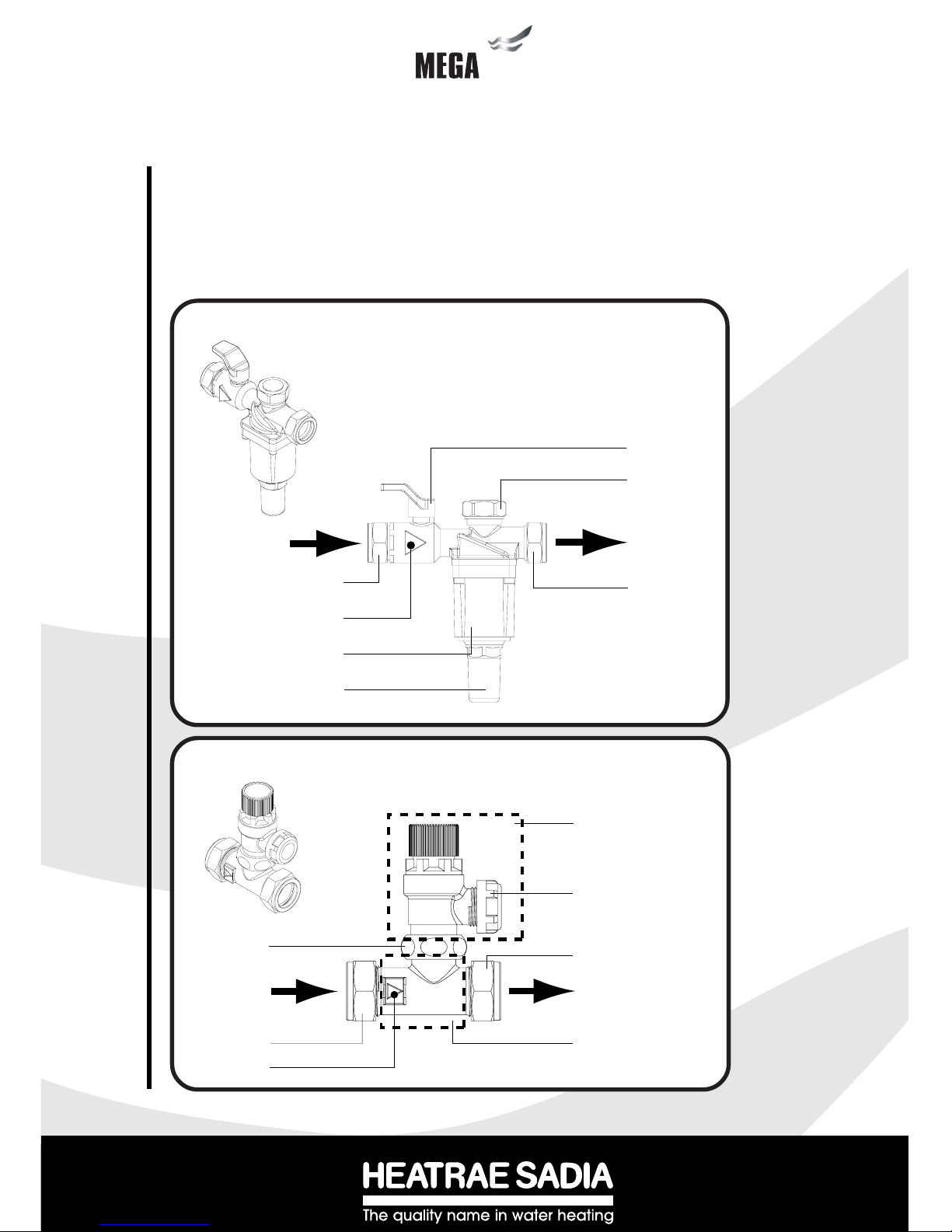
Diagram 2 - Cold Water Combination Valve
Diagram 3 - Expansion Core Unit
ISOLATING VALVE
MAINS IN
22MM
COMPRESSION
CONNECTION
PRESSURE REDUCING
VALVE HOUSING
PRESSURE REDUCING
VALVE CARTRIDGE
(3 BAR)
22MM
COMPRESSION
CONNECTION
OUTLET TO
MEGAFLO
EXPANSION VALVE
CONNECTION (IF
ONE-PIECE VALVE
IS REQUIRED)
TAKE NOTE OF
FLOW DIRECTION
EXPANSION RELIEF VALVE
DISCHARGE CONNECTION
EXPANSION RELIEF VALVE
FROM COLD
WATER
COMBINATION
VALV E
OUTLET TO
MEGAFLO
22MM COMPRESSION
CONNECTION
EXPANSION CORE UNIT
(INCORPORATES
CHECK VALVE)
MOUNTING NUT
22MM COMPRESSION
CONNECTION
TAKE NOTE OF
FLOW DIRECTION
8
8
techtech
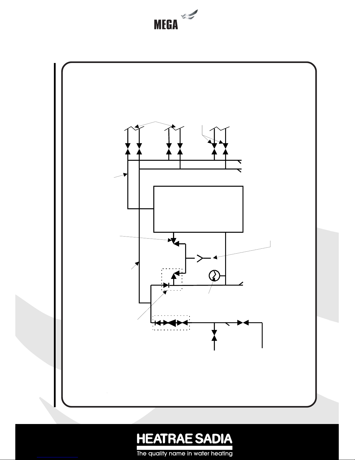
Tundish
Megatech
Solar
Discharge pipe to atmosphere
(See Section 3.9 “Discharge
Pipework“)
KEY
MCWS Mains cold water supply
HWS Hot water service
SC Stop Cock
DOC Drain Off Cock
Temperature/Pressure
Relief Valve
Balanced cold water
draw off
Balanced HWS and
MCWS to bathrooms,
showers,cloakrooms,
etc.
Isolating/Regulating
Valves as required
HWS supply
Expansion Core
Unit (combined
Expansion Relief
Val ve /C heck Val ve)
SC
SC
DOC
EXPANSION
VESSEL
Incoming Cold
Water Main
MCWS to Kitchen
(unbalanced cold
mains supply)
Cold Water Combination
Valve incorporating
Pressure Reducing Valve,
Isolating Valve, Strainer
and Check Valve
NB Expansion Valve
tapping must be blanked
off
DOC DOC
DOC
Diagram 4 - Schematic installation diagram using Cold Water Combination Valve in
conjunction with Expansion Core Unit
Installation - General
9
tech
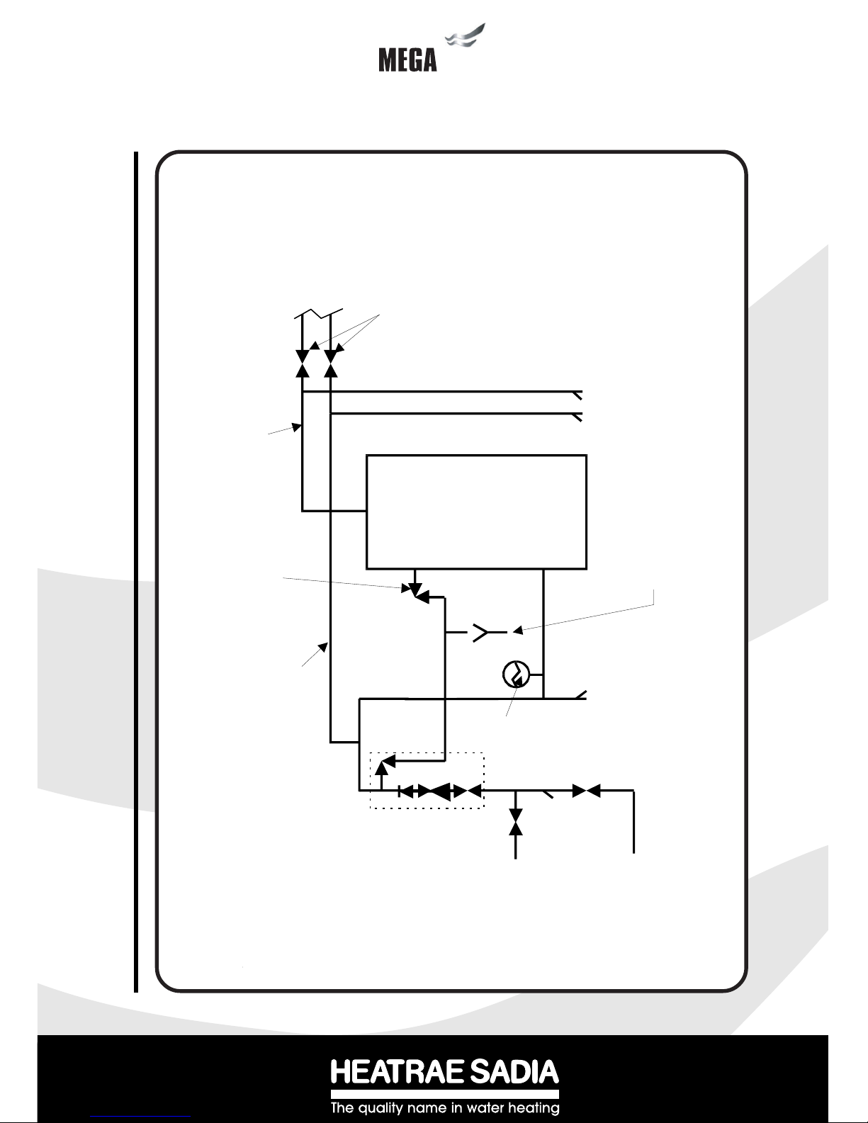
Diagram 5 - Schematic installation diagram using Cold Water Combination Valve
Tundish
Megatech
Solar
Discharge pipe to atmosphere
(See Section 3.8 “Discharge
Pipework“)
KEY
MCWS Mains cold water supply
HWS Hot water service
SC Stop Cock
DOC Drain Off Cock
Temperature/Pressure
Relief Valve
Balanced cold water
draw off to shower
mixer valves (Note:
tapping must be min.
3m from Megaflo
inlet connection)
Balanced HWS and
MCWS to each
shower.
Isolating/Regulating
Valves as required
HWS supply
SC
SC
DOC
Incoming Cold
Water Main
Incoming Cold
Water M ain
MCWS to Kitchen
and drinking water
outlets (unbalanced
cold mains supply)
Cold Water Combination
Valve incorporating
Pressure Reducing Valve,
Isolat ing Valve, Strainer
and Check Valve and
Expansion Relief Valve
DOC DOC
DOC
EXPANSION
VESSEL

10
10
techtech
3.5 DRAIN TAP
A draining tap is supplied and should be installed in the cold water supply to the Megatech Solar unit
between the Cold Water Combination Valve (or Expansion Core Unit if being used) and the heater
at as low a level as possible (see Diagram 1). It is recommended that the outlet point of the drain
pipe work be at least 1 metre below the level of the heater (this can be achieved by attaching a hose
pipe to the drain tap outlet spigot). The drain tap supplied provides very good water flow control and
blanking cap for extra security.
3.6 OUTLET PIPEWORK
Ideally the pipework from the Megatech Solar to the outlet fittings should be in 22mm pipe with short
runs of 15mm pipe to showers and basin taps. Small bore pipe can also be used to suit some taps,
but runs should be of minimum length. Pipe sizes may vary due to system design.
3.7 EXPANSION VESSEL
The Expansion Vessel accommodates expansion that results from heating the water inside the unit. The
unit is pre-charged at 0.35 MPa (3.5 bar). The Expansion Vessel must be connected between the Cold
Water Combination Valve and the Megatech Solar (see Diagram 1). The location of the Expansion
Vessel should allow access to recharge the pressure as and when necessary, this can be done using
a normal car foot pump. It is recommended that the Expansion Vessel is adequately supported. An
Expansion Vessel wall mounting bracket is supplied for this purpose.
NOTE: DO NOT USE THE POTABLE WATER EXPANSION VESSEL SUPPLIED WITH THE
MEGATECH SOLAR FOR ANY OTHER PURPOSE. IT MUST NOT BE USED IN PLACE OF
THE SOLAR PRIMARY SYSTEM EXPANSION VESSEL.
3.8 SECONDARY CIRCULATION
If a secondary circulation system is required it should be connected to the Megatech Solar as
shown in Diagram 6 via the connection provided. The secondary return pipe should be in 15mm
pipe and incorporate a check valve to prevent backflow. A suitable WRAS approved bronze
circulation pump will be required. On large systems, due to the increase in system water content, it
may be necessary to fit additional expansion volume to the system by fitting an external expansion
vessel to the secondary circuit. This should be done if the capacity of the secondary circuit exceeds
10 litres.
Pipe capacities (copper)
15mm o/d = 0.13 litres per metre run (10 litres = 77m)
22mm o/d = 0.38 litres per metre run (10 litres = 26m)
28mm o/d = 0.55 litres per metre run (10 litres = 18m)
Secondary circulation is NOT recommended for direct electric units being used on Off
Peak electricity tariffs. The secondary circulation return must not be connected to the inlet
as this would lead to indirect heating of the dedicated solar buffer volume.
Installation - General
11
tech
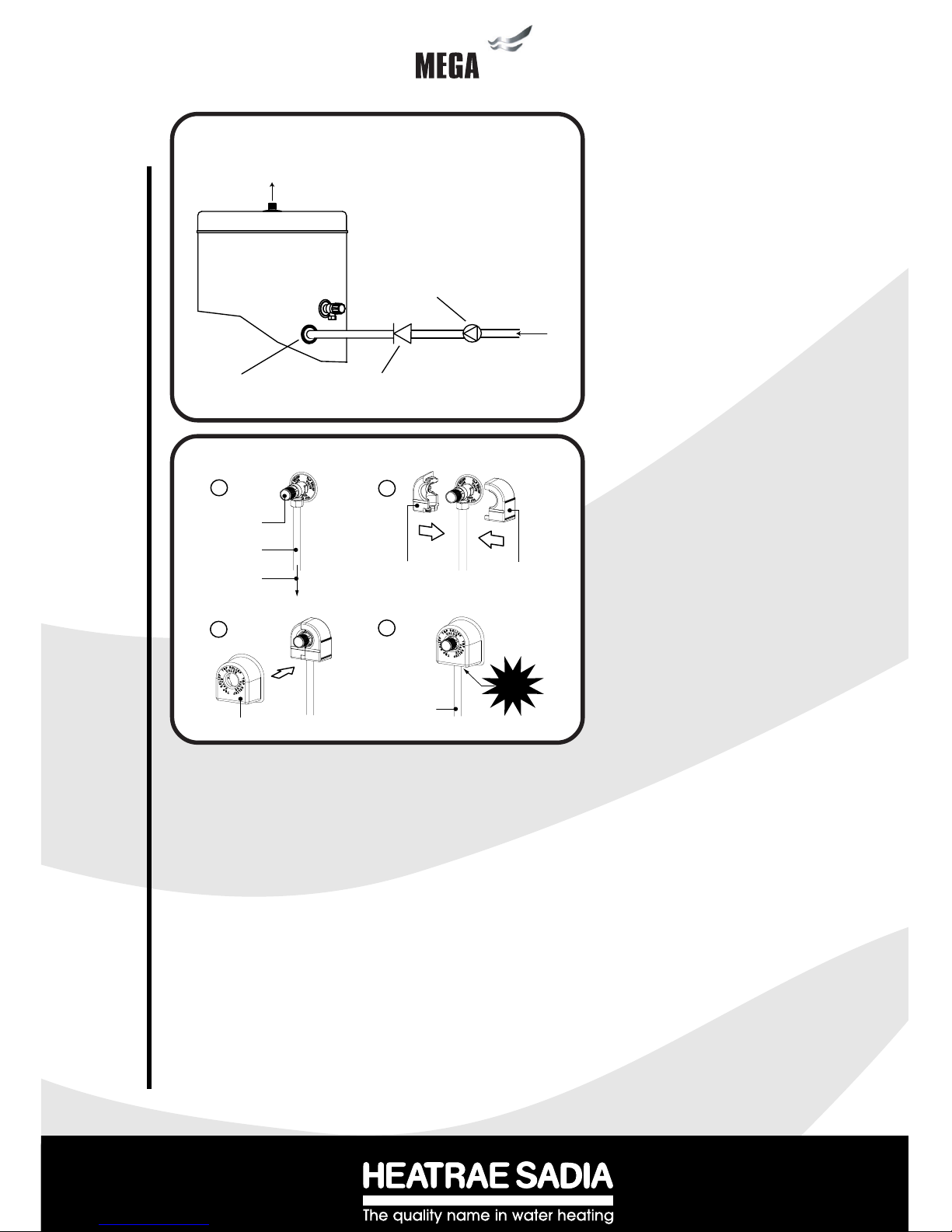
Diagram 6 - Secondary circulation connection
3.9 T&P RELIEF VALVE INSULATION
A set of insulating components is supplied with the Megaflo water heater and should be installed to
gain maximum heat and energy saving benefits. See Diagram 7 for installation instructions.
3.10 WARNINGS
i) Under no circumstances should the factory fitted Temperature/Pressure Relief Valve
be removed other than by Authorised Heatrae Sadia personnel. To do so will
invalidate any guarantee or claim.
ii) The Cold Water Combination Valve must be fitted to the mains
water supply to the Megatech unit.
iii) No control or safety valves should be tampered with.
iv) Water may drip from the discharge pipe of the pressure relief device (Expansion
Valve) and this pipe must be left open to atmosphere. The discharge pipe should not
be blocked or used for any other purpose.
SECONDARY RETURN
CONNECTION
CHECK VALVE
SECONDARY
CIRCULATION PUMP
OUTLET
SECONDARY
RETURN
T&P RELIEF
VALV E
DISCHARGE
PIPEWORK
TO TUNDISH
'FEMALE'
INSULATING
PIECE
'MALE'
INSULATING
PIECE
DISCHARGE
PIPE
PLASTIC
COVER
CLIP
INTO
PLACE!
A
B
C
D
Diagram 7 - Installation of T&P Insulating set
 Loading...